Compex Systems WPJ344 WIRELESS ACCESS POINT User Manual ah
Compex Systems Pte Ltd WIRELESS ACCESS POINT ah
users manual
•
CompexWRT and OpenWRT firmware supported
•
Qualcomm-Atheros 533MHz Networking Processor,WASP Series
•
Dual Radio Solution (one 2x2 11n 2.4GHz on-board radio and one miniPCIe
slot that supports all Compex WLE series, including 802.11ac radio)
•
Integrated 48V 802.3af (alternative 24V PoE available)
•
Support 2 x Gigabit Ethernet Port
•
Optional: support USB Extension
Dual Band Gigabit Wireless Embedded Board
Model: WPJ344
Applications
•
Dual Band, Dual Concurrent AP
•
802.11bgn AP
•
Point to Point / Point to MultiPoint
•
Base Station
•
CPE
ac wave series
Features
Technical Specifications
System Information
Processor
Qualcomm-Atheros AR9344 MIPS 74Kc
System Memory
128MB(64*2) DDR2
NOR Flash
8MB (max 16MB optional)1
MiniPCI Slot
1 x 9.2mm MiniPCIe slot
Ethernet
2 Gigabit ports with Auto-MDI/X
Extras
Serial Port2, JTAG3, Reset Button, Surge Arrestor, Watchdog Timer
Power Solutions
High voltage
DC Jack Input:24-48V, Passive PoE: 24-48V, IEEE 802.3af/at PoE
Standard 802.3af PoE input:(Optional)4
Low voltage
DC Jack Input: 9-24V, Passive PoE: 12-24V
Power Consumption
7W
RoHS Compliance
Yes
Humidity
Operating: 5% to 95% (non-condensing)
Storage: Max.90% (non-condensing)
Temperature Range
Operating:-20ºC to 70ºC
Storage: -40ºC to 90ºC
Dimension
117 x 105 x 17 (mm)
2.4GHz
On-board Radio
Transmit
Power
Data Rate
Aggregate Power
1M
25dBm
11M
23dBm
6M
25dBm
54M
22dBm
HT20 MCS0
25dBm
HT20 MCS7
22dBm
HT40 MCS0
25dBm
HT40 MCS7
22dBm
Receiver
Sensitivity
Data Rate
6M
-90dBm
54M
-75dBm
HT20 MCS0
-90dBm
HT20 MCS7
-72dBm
HT40 MCS0
-88dBm
HT40 MCS7
-70dBm
Max of concurrent
associations
Encryption
Client
Latency
TCP
[each client upload and download
randomly from 384Kbps to 768Kbps]
UDP
[each client upload
and download 2Mbps]
WPA2-PSK
<100ms
Single radio
Dual radio
Single radio
Dual radio
40 clients
70clients
(35 per radio)
20 clients
30clients
(15 per radio)
1 Depends on Order Configurations
2 Serial Port is a 4-pin header (TTL) + Serial Converter is available to change the TTL signals on board to RS232 signals
for debugging.Configurations are subjec to change without notification
3 JTAG Port is a 14-pin header + JTAG kit is for writing your own developed loader and firmware directly
4 In this mode, it can be powered from 802.3af/3at PoE switches and PoE injectors. It is able to return a PD classification
of 0. The DC jack can accept a voltage range of 24V to 56V but the PoE input needs a minimum voltage of 36V
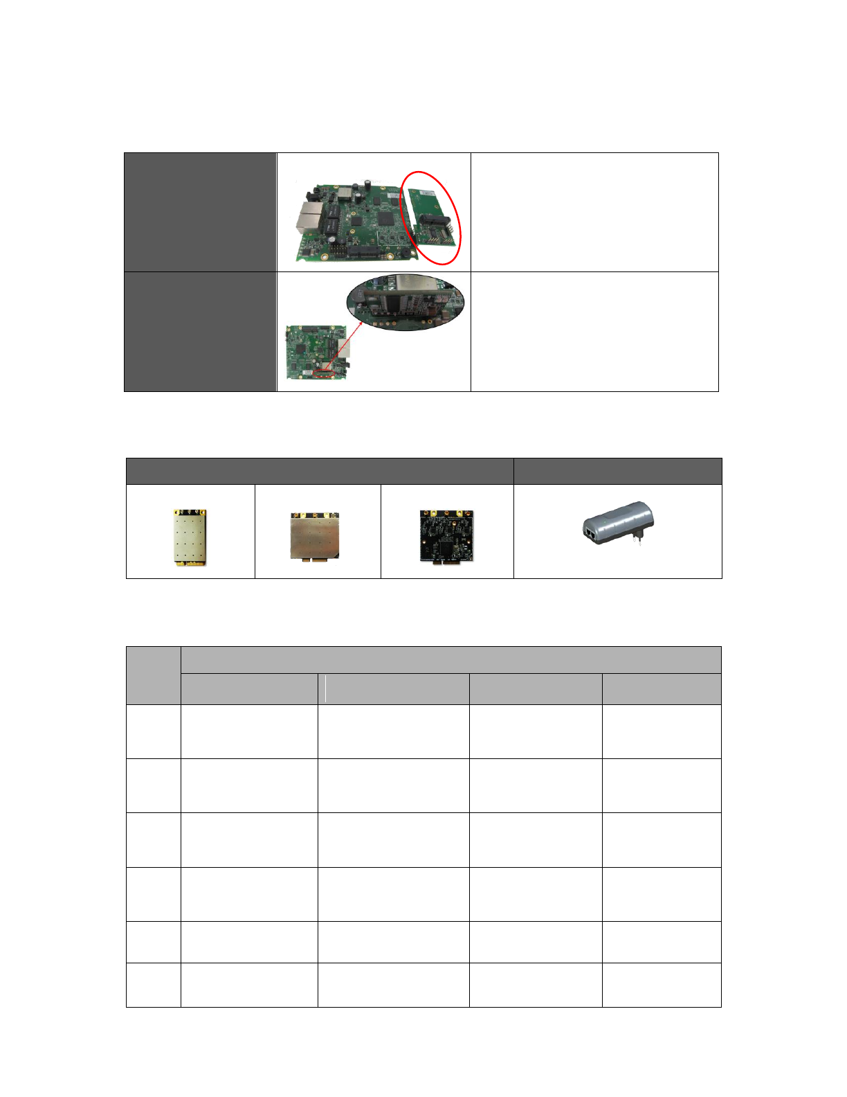
Related Products
802.11ac 5GHz miniPCIe
Gigabit Power over Ethernet
WLE900VX
WLE600V5-23
WLE900V5-23
POE2408
- Output Voltage: 24VDC
- Max Output Watts: 19W
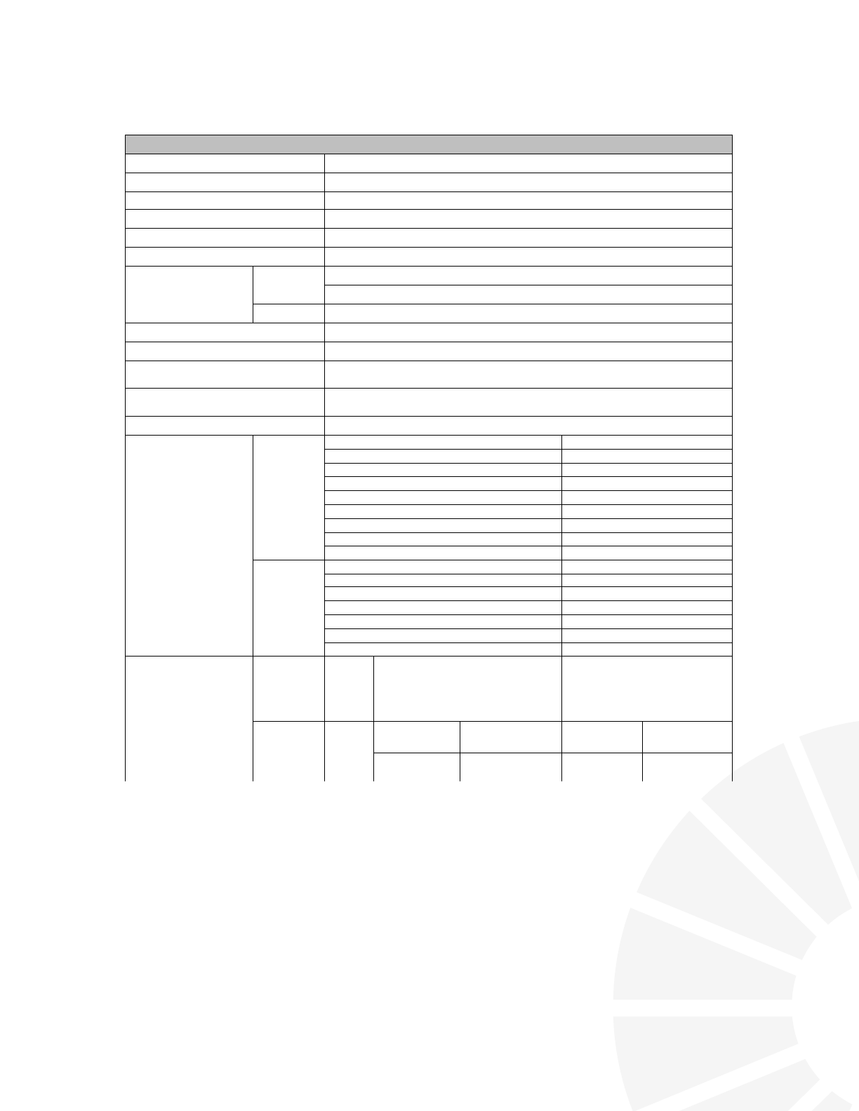
Optional configuration
USB Extension
(USB HUB BOARD-1.00-ST)
USB board
External board:
can support 3 x USB 2.0 ports and
1 x miniPCIe-based USB 2.0 only interface
(e.g. 3G modems)
PSE pass-thru module
(P-PSE-M-6A03-SPL)
PSE pass-thru module: Optional module to
allow power to pass through the 2nd Ethernet
port to an IEEE 802.3af/at compatible device,
such as a surveillance camera
Model
Extended applications
USB signal
USB External board
(USB HUB BOARD-1.00-ST)
802.3af PoE pass-thru
802.3af
PoE power supply
WPJ344
Support 1× USB 2.0 port
support 3 x USB 2.0 ports
and
1 x miniPCIe-based USB
2.0 only interface
Optional
(PSE pass-thru module)
support
WPJ558
Support 1× USB 2.0 port
or
PCIe slot Support Third
Party 3G/LTE Module
support 3 x USB 2.0 ports
and
1 x miniPCIe-based USB
2.0 only interface
support
WPJ342
Support 1× USB 2.0 port
or
PCIe slot Support Third
Party 3G/LTE Module
Optional
(802.3af module)
WPJ531
Support 1× USB 2.0 port
or
PCIe slot Support Third
Party 3G/LTE Module
Optional
(802.3af module)
WP546
Support 2× USB 2.0 port
Optional
(PSE pass-thru module)
support
WP543
Support 2× USB 2.0 port
support
Compex embedded board extended applications list
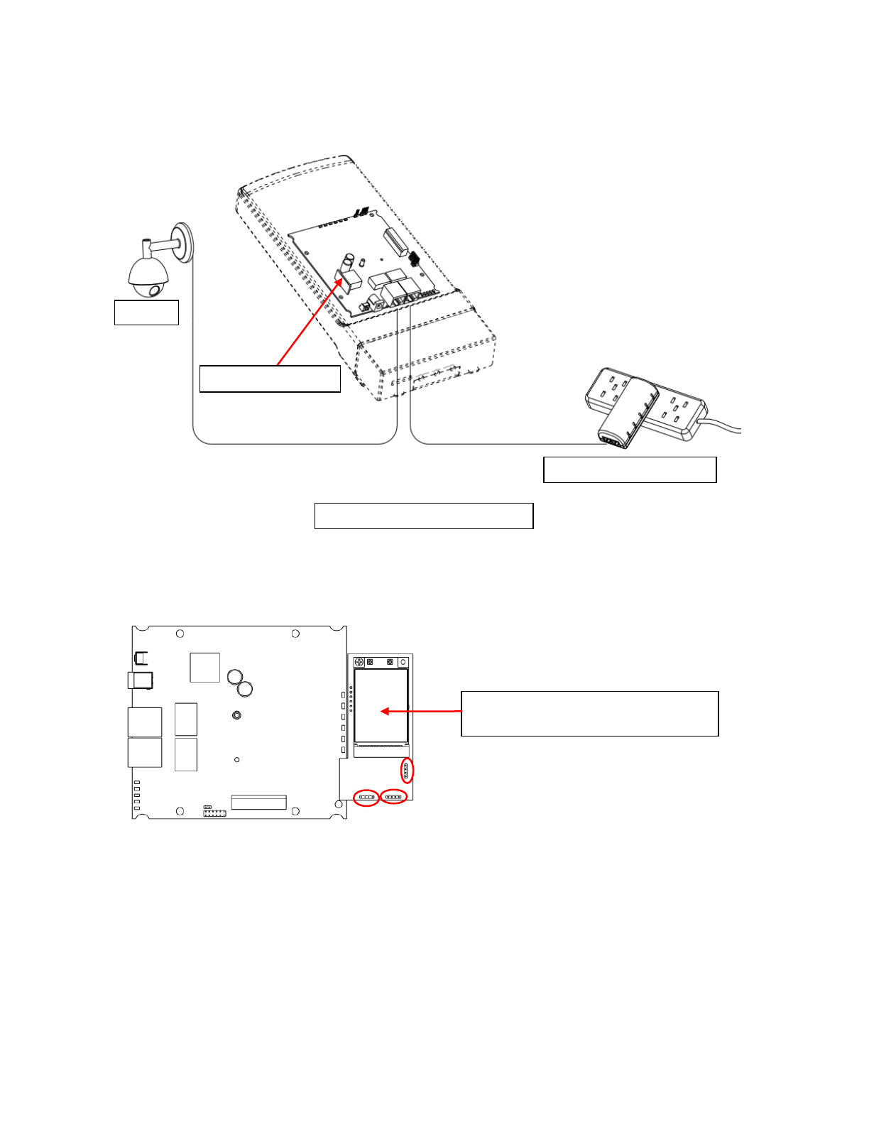
Product application:
Camera
Gigabit Power over Ethernet
PSE pass-thru module
WPJ344 with PSE pass-thru module
WPJ344 with USB External board
can support 3 x USB 2.0 ports or
1 x miniPCIe-based USB 2.0 only interface
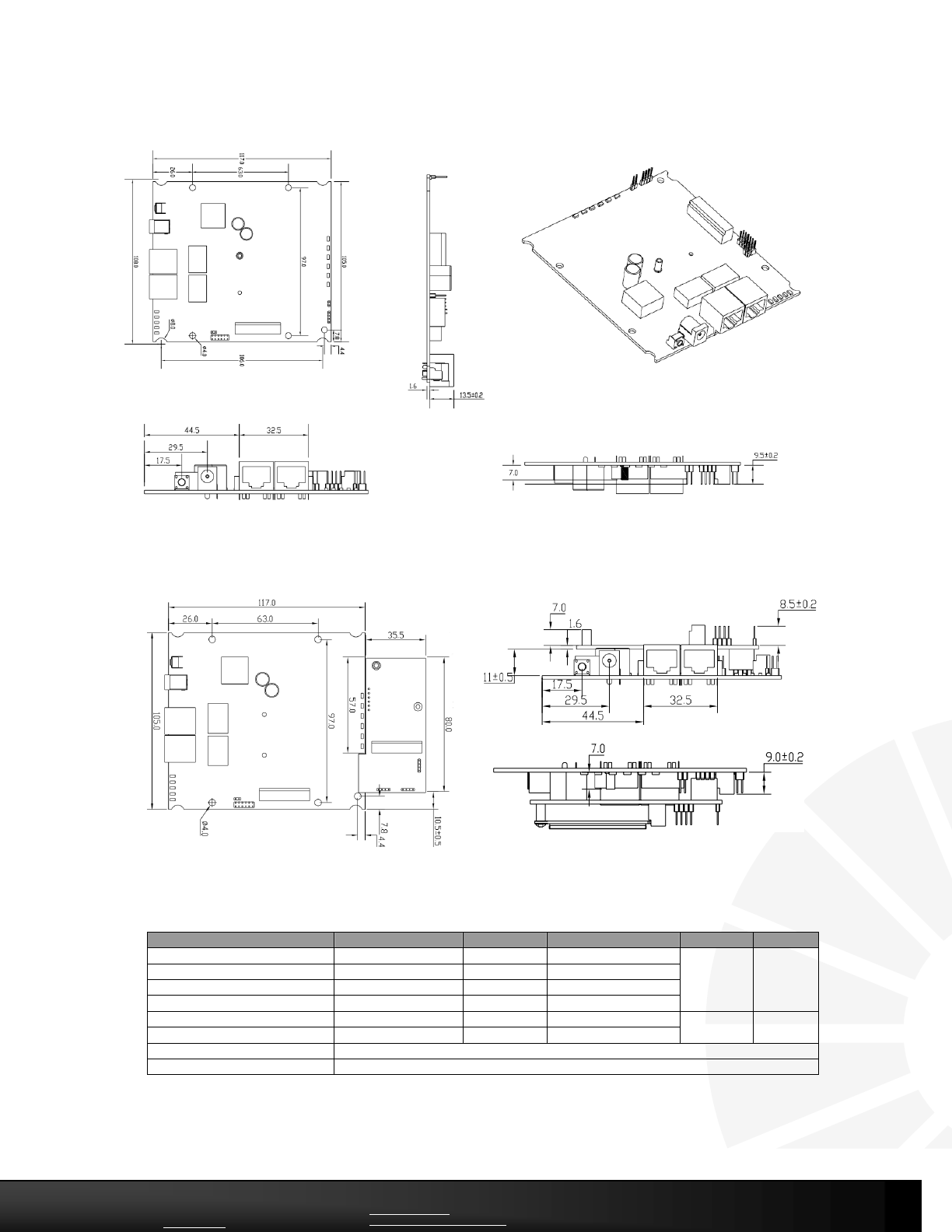
Dimension Drawing
Ordering Information
Item Code
Version
PSE module
L/H voltage Power
NOR Flash
Memory
WPJ344HV 6A06PC8128BR
CompexWRT
NO
High Voltage (48V)
8MB
128MB
WPJ344LV 6A06PC8128BR
CompexWRT
NO
Low Voltage (24V)
WPJ344HV 6A6BCW8128BRPSE
CompexWRT
Yes
High Voltage (48V)
WPJ344LV 6A6BCW8128BRPSE
CompexWRT
Yes
Low Voltage (24V)
WPJ344HV 6A06PC16128BR
CompexWRT
NO
High Voltage (48V)
16MB
128MB
WPJ344LV 6A06PC16128BR
CompexWRT
NO
Low Voltage (24V)
P-PSE-M-6A03-SPL
PoE pass-Thru module
USB HUB BOARD-1.00-ST
USB External board
Compex Systems Pte Ltd
135 Joo Seng Road #08-01
Singapore 368363
Tel: +65 6286 2086
Fax: +65 6280 9947
Email: sales@compex.com.sg
Compex (Suzhou) Co Ltd
No.12 ChuangTou Industrial Square
LouFeng North, Suzhou Industrial Park
Suzhou, Jiangsu Province China 215122
Tel: +86 512 62950050
Fax: +86 512 62950026
www.compex.com.sg
www.facebook.com/compexsystems
Copyright 2013 Compex Systems. All rights reserved. COMPEX and the COMPEX logo are registered trademarks
of COMPEX Inc. While every effort is made to ensure the information is accurate, Compex does not accept
liability for any errors or mistakes that may arise. All specifications are subject to change without notice.
Dimension Drawing with USB external board

Federal Communications Commission (FCC) Interference Statement
This equipment has been tested and found to comply with the limits for a Class B digital device, pursuant to Part 15 of the FCC Rules.
These limits are designed to provide reasonable protection against harmful interference in a residential installation. This equipment generate, uses and can
radiate radio frequency energy and, if not installed and used in accordance with the instructions, may cause harmful interference to radio communications.
However, there is no guarantee that interference will not occur in a particular installation. If this equipment does cause harmful interference to radio or television
reception, which can be determined by turning the equipment off and on, the user is encouraged to try to correct the interference by one of the following measures:
Reorient or relocate the receiving antenna.
Increase the separation between the equipment and receiver.
Connect the equipment into an outlet on a circuit different from that to which the receiver is connected.
Consult the dealer or an experienced radio/TV technician for help.
This device complies with Part 15 of the FCC Rules. Operation is subject to the following two conditions:
(1) This device may not cause harmful interference, and (2) this device must accept any interference received, including interference that may cause undesired
operation.
FCC Caution: Any changes or modifications not expressly approved by the party responsible for compliance could void the user’s authority to operate this
equipment.
RF exposure warning
This equipment complies with FCC radiation exposure limits set forth for an uncontrolled environment.
This equipment must be installed and operated in accordance with provided instructions and the antenna(s) used for this transmitter must be installed to provide a
separation distance of at least 20 cm from all persons and must not be collocated or operating in conjunction with any other antenna or transmitter.