Computational Systems orporated 8000RF Laser Alignment Fixture User Manual Chapter 5
Computational Systems Incorporated Laser Alignment Fixture Chapter 5
UserManual.wiki
>
Computational Systems orporated
>
8000RF User Manual
>
Chapt 5 6 7 8 9
Contents
1.
Appendix
2.
Chapt 1 2 3
3.
Chapt 5 6 7 8 9
4.
Chap 4 pp 1 to 10
5.
Chap 4 pp 11 to 40
6.
Chap 4 pp 41 to 52
7.
Manual Intro and TOC
Chapt 5 6 7 8 9
Navigation menu
Upload a User Manual
Namespaces
Wiki Guide
HTML
PDF
Info
Views
User Manual
Discussion / Help
Navigation
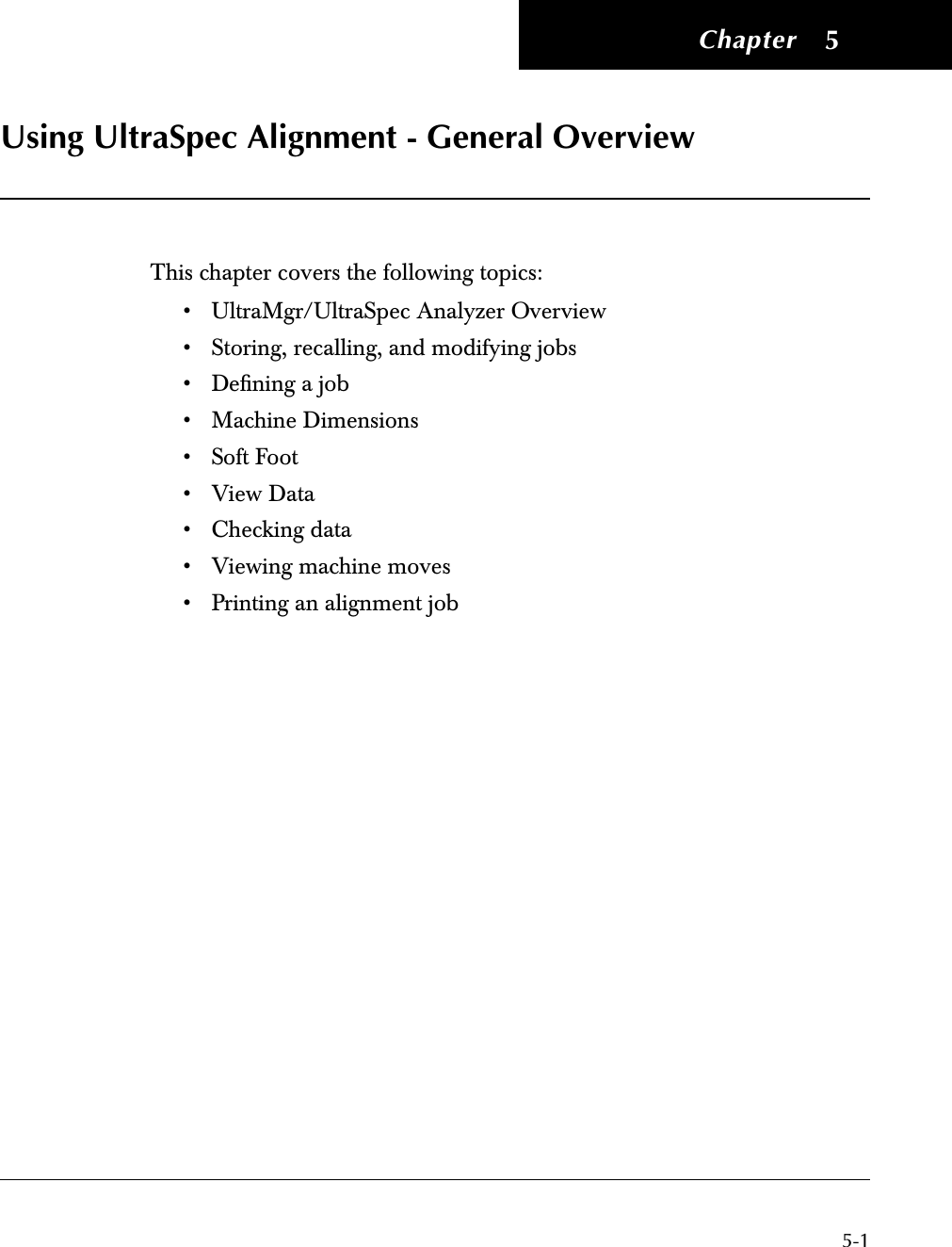
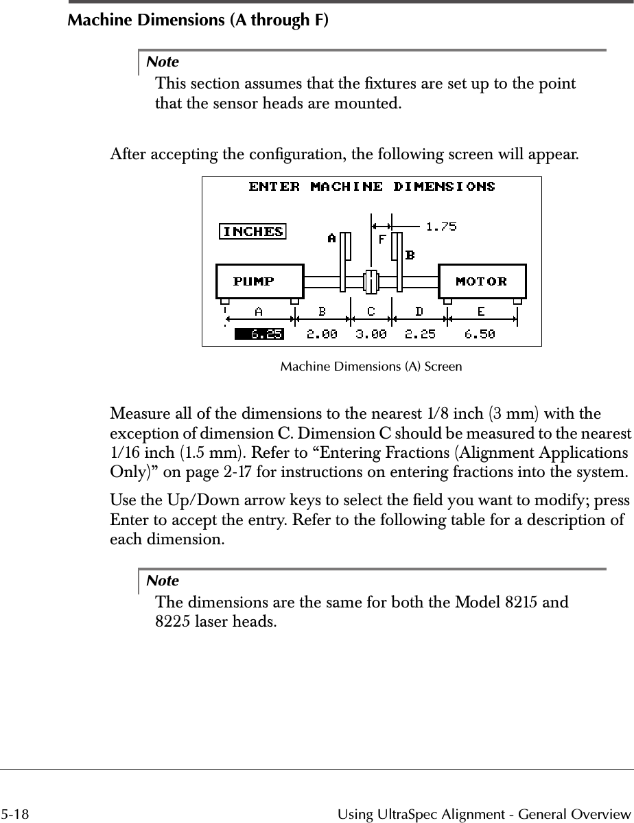
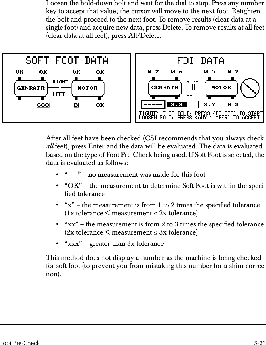
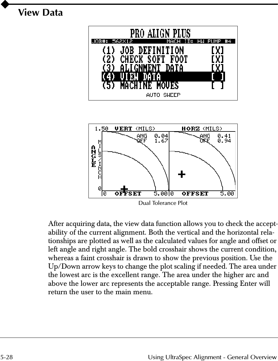
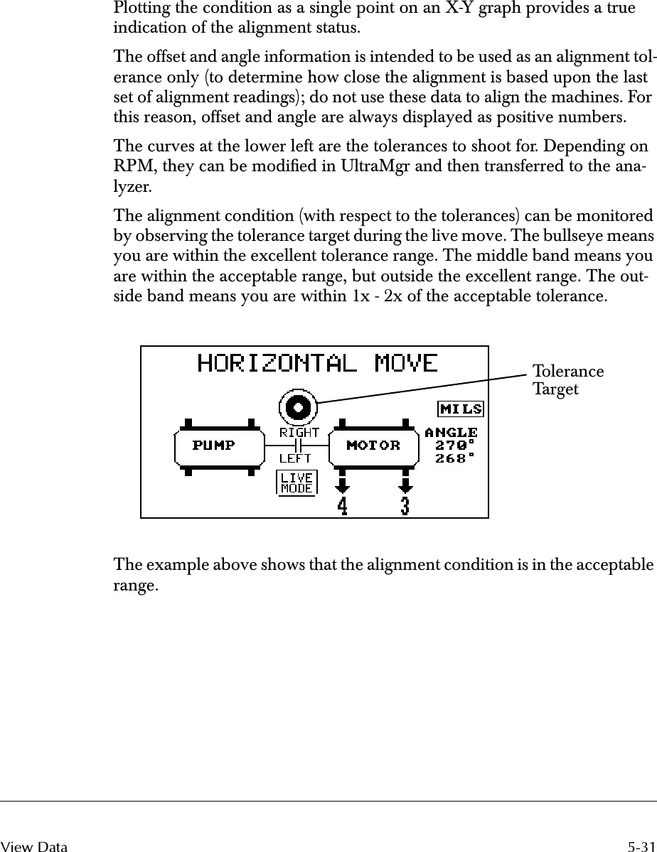
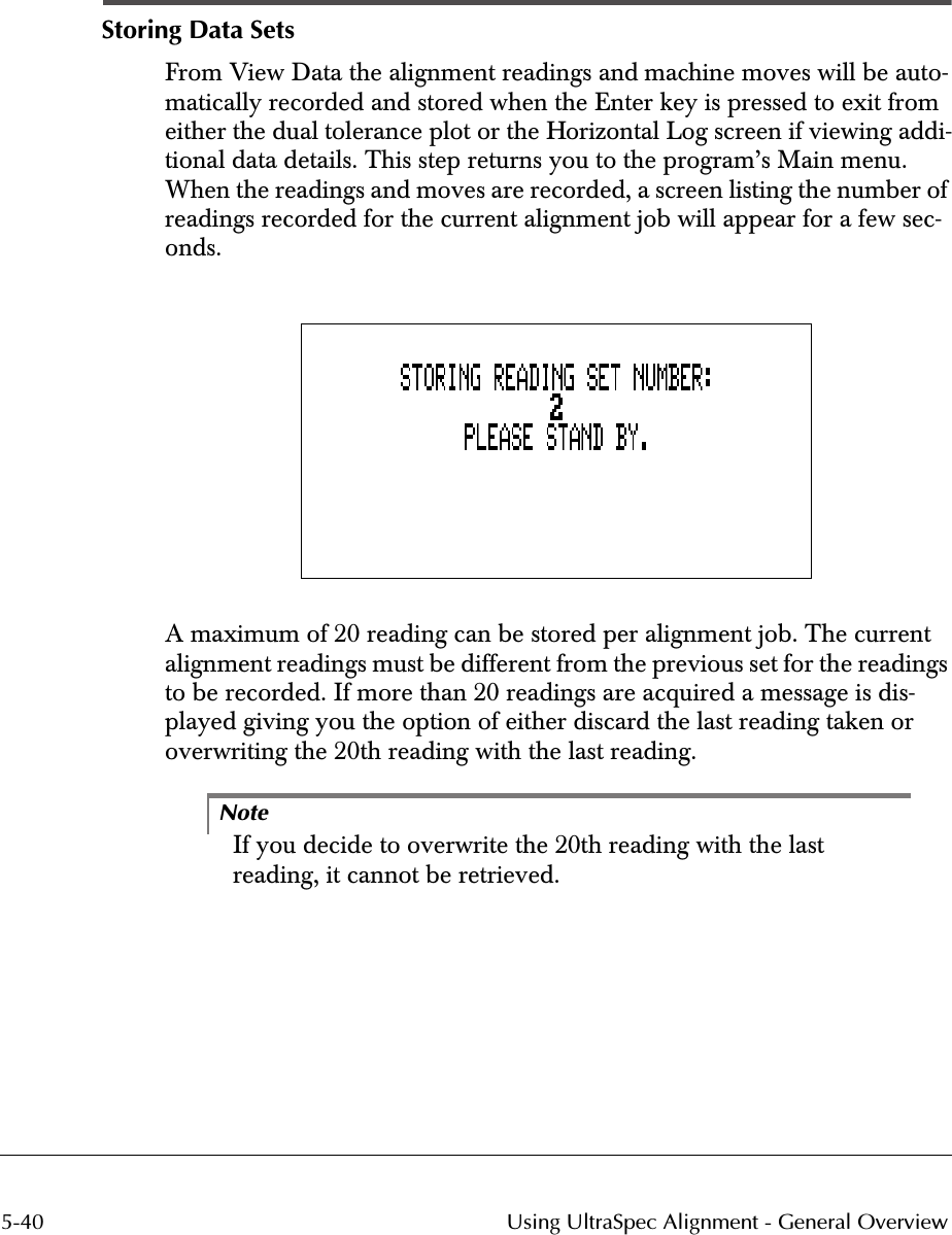
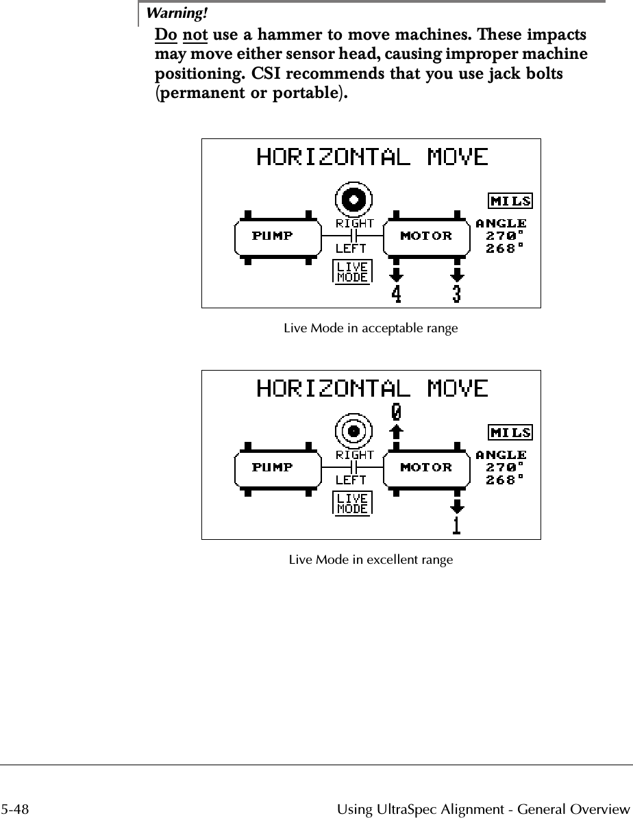
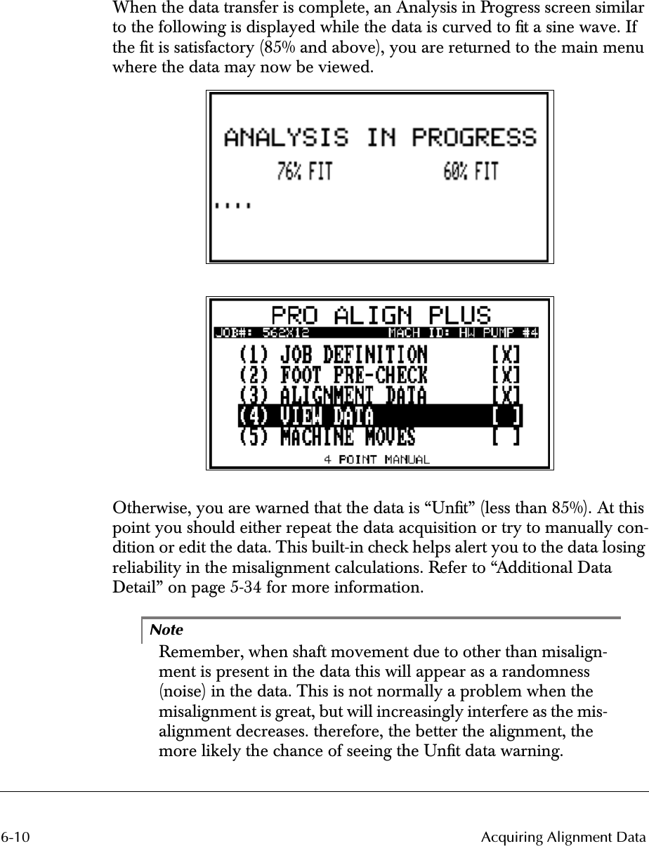
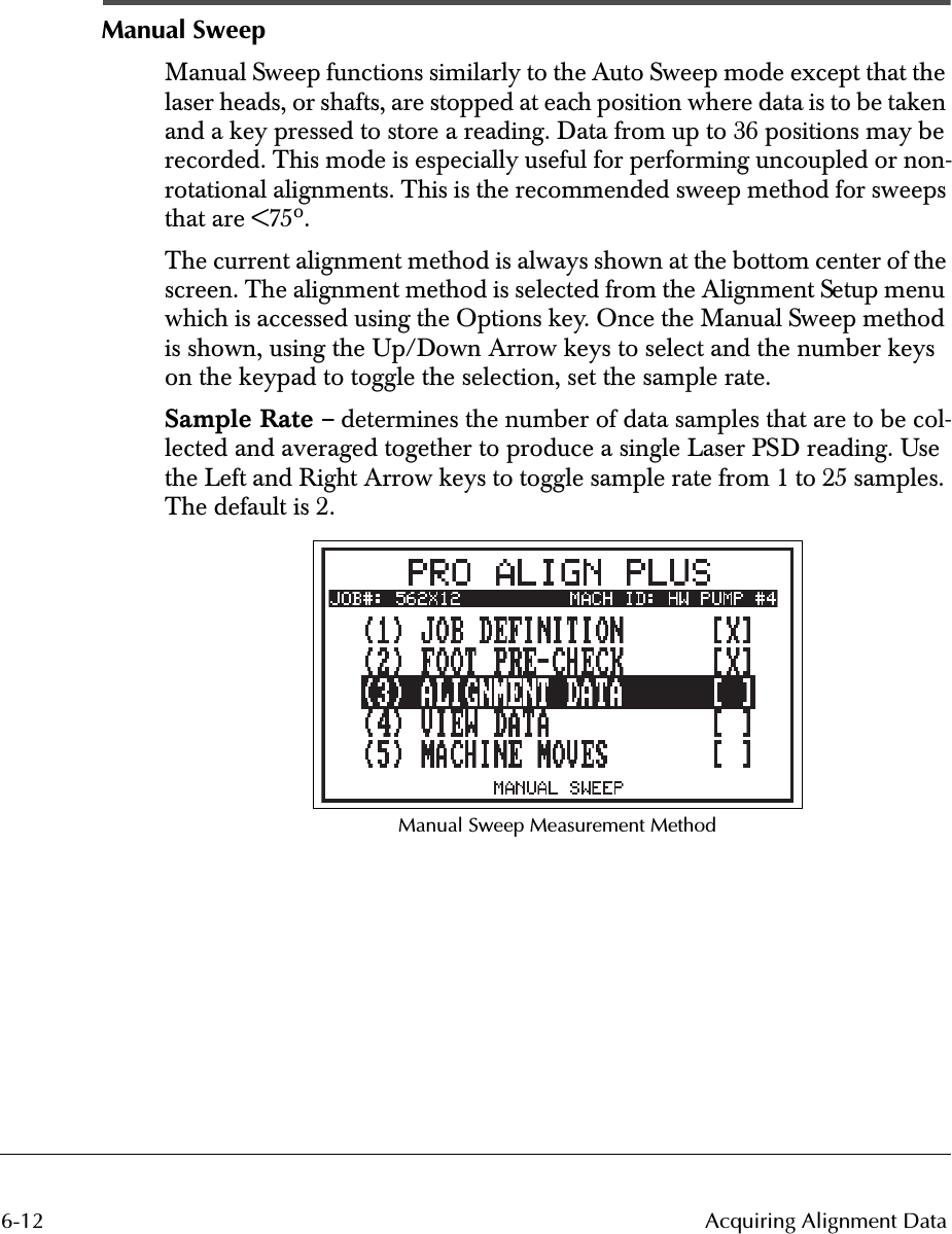
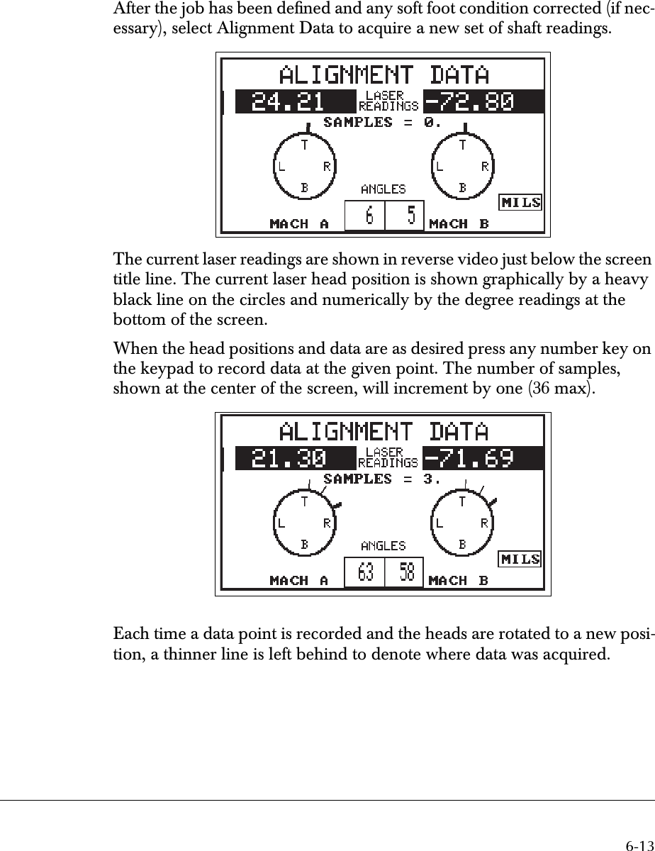
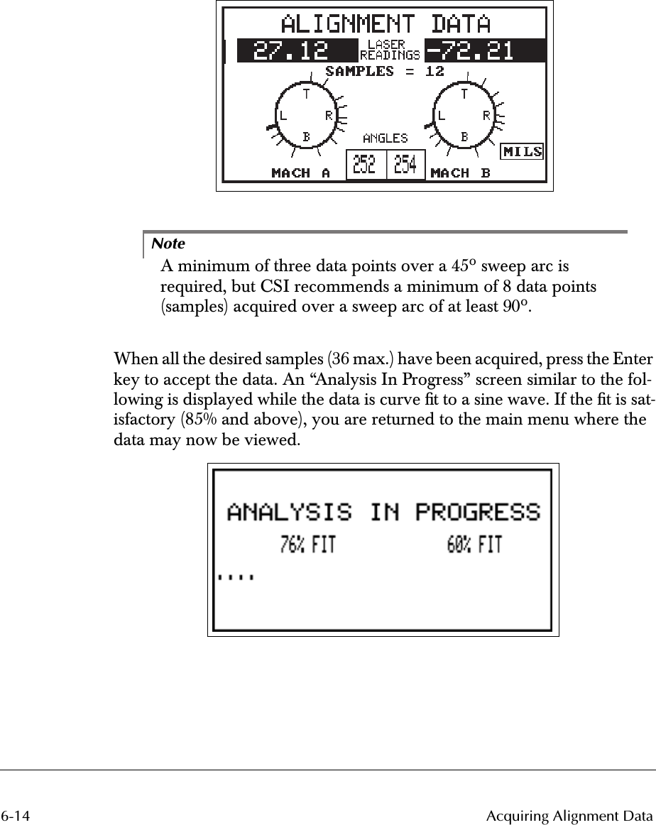
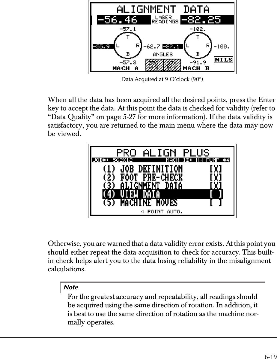
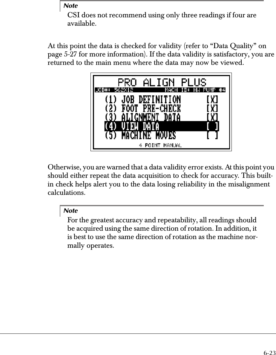
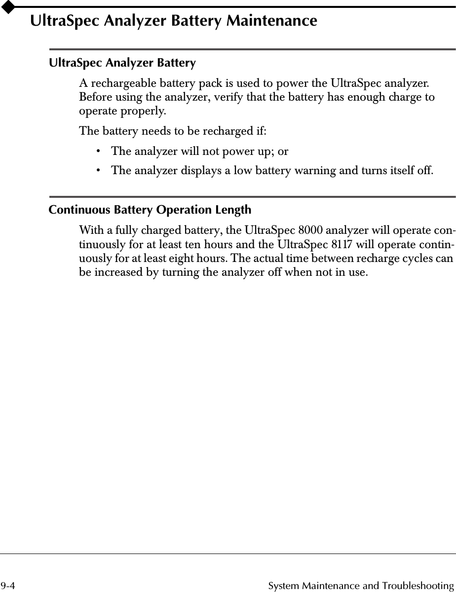
![5-22 Using UltraSpec Alignment - General OverviewFoot Pre-CheckWhen Foot Pre-Check is selected (from the main menu) and the Job Defi-nition screen is completed, a screen similar to the one below on the left will be displayed. The screen that is displayed depends on the type of Foot Pre-Check selected (Soft Foot or Frame Distortion Index [FDI]). For more infor-mation, see the Appendix heading, “Foot Pre-Check Types” on page -1.Use the Enter key to move to the Soft Foot/FDI Locator screen (on the right). Ensure that the sensor heads are at the top (as shown) or, at the bottom position (180°). After verifying that all hold-down bolts are tight, press Enter to proceed to the Soft Foot/FDI Data screen shown below.Use the Up/Down arrow keys to select the foot to be checked. In the screen above, the right outboard foot of the generator has been selected. Press Delete to start.](https://usermanual.wiki/Computational-Systems-orporated/8000RF.Chapt-5-6-7-8-9/User-Guide-134688-Page-22.png)