Computational Systems orporated 8000RF Laser Alignment Fixture User Manual Chapter 5
Computational Systems Incorporated Laser Alignment Fixture Chapter 5
Contents
Chapt 5 6 7 8 9

Chapter
5-1
5
Using UltraSpec Alignment - General Overview
This chapter covers the following topics:
• UltraMgr/UltraSpec Analyzer Overview
• Storing, recalling, and modifying jobs
• Defining a job
• Machine Dimensions
• Soft Foot
• View Data
• Checking data
• Viewing machine moves
• Printing an alignment job
1
5-2 Using UltraSpec Alignment - General Overview
General Overview
This section contains overviews of UltraMgr and the UltraSpec analyzer,
the three alignment methods, menu maps of the UltraSpec analyzer, and an
explanation of the Main Menu.
UltraMgr/UltraSpec Analyzer Overview
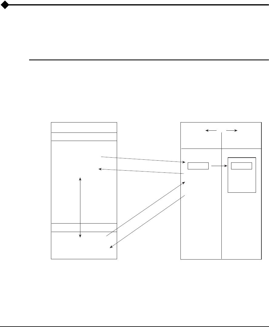
The figure below shows how jobs can be moved in and out of various areas
of UltraMgr’s database and the analyzer. Definitions of the job types follow.
UltraMgr/UltraSpec Analyzer Overview
UltraSpec Analyzer - (Slave)
Current Job
Area
Stored Job(s)
Area
002 Pump
UltraMgr (PC) - (Master)
Unassigned Job(s) Area
UltraMgr Database
Store
001 Motor 001 Motor
* One job
at a time
Station:
Machine:
Station:
Machine:
Load
Dump
Load
Dump
* You can
store up to 90
alignment jobs
in the UltraSpec
Analyzer
* Jobs must
be stored
before they
can be sent
to the UltraMgr
database
003 Fan
004 Turbine
Assigned Job(s) Area
Recall

5-3
General Overview
Note
This manual and the UltraSpec Analyzer manual use the terms
Station and Machine. In RBMware compatible UltraMgr
v4.00 and later, a station may be preferred to as Area, and
Machine may be referred to as Equipment unless redefined by
the user.
Note
Data from the 8215 and 8225 laser heads are compatiable with
UltraMgr v4.40 and later.
Definitions of the job types shown in the figure are:
•
Assigned jobs
– jobs that have been assigned to a machine.
•
Unassigned jobs
– jobs that have been moved from the Stored Jobs
area of the analyzer into the UltraMgr database but have not been
assigned to a machine. Using UltraMgr, you can also change a job
from Assigned to Unassigned status.
•
Stored jobs
– located in the Stored Jobs area of the Analyzer. Cur-
rent jobs that are saved become stored jobs and are placed in the
Stored Jobs area; also, all jobs that are loaded from the UltraMgr
database are placed in this area and become stored jobs.
•
Current job
– job currently displayed in the working area (only one
job can be displayed at a time).
The following cases may help you to understand how jobs are moved
around in the analyzer and back and forth to UltraMgr. When beginning a
job (in the Current Job location), there are normally two choices. Either
start from ground zero and create, configure, and name an entirely new job
or, (if available) recall a job from the Stored Job(s) area.
Case 1
– If you create and configure an entirely new job in the analyzer’s
Current Job area and you want to keep it, you must copy it into the Stored
Job area by using the Store Job command in the Alignment Options menu.
From there (using the UltraMgr database program on a PC), you can down-
load it into a section of UltraMgr known as the Unassigned Area.

5-4 Using UltraSpec Alignment - General Overview
Continuing with the UltraMgr program, you can then assign the job to a
machine and station thereby fully integrating the job information into the
UltraMgr database. If for some reason you do not want to assign the job to
a machine and station, you can leave it in the Unassigned Area.
In either case, you can then use UltraMgr to Load the job back into the ana-
lyzer and from that point, you can recall it into the Current Job area where
you have full editing capabilities.
Case 2
– You begin with a recalled job from the Stored Job area. An impor-
tant concept to remember is that a job recalled into the Current Job area is
essentially a
copy
of the original job which remains in the Stored Job area.
This allows you to modify, renumber, and save the
copy
thereby creating an
entirely new job (without affecting the original job).
However, if you want to change the original job (instead of creating a new
one), make the desired changes and, when prompted about saving the orig-
inal job, answer No. This allows you to overwrite the data in the original
job with your new data.
Case 3
– This case is referred to as job “cloning” and provides optimum
use of the entire system, including UltraMgr.
This procedure will be the one
commonly used after an alignment job has been archived in UltraMgr
. An old job
performed on the same machine can be loaded into the analyzer and used
as a template for the job to be performed. The old job contains information
on the job setup, the latest alignment condition (machine moves and toler-
ances), and concerns or observations (notes). You should review this infor-
mation before clearing out the readings and notes. If desired, edit the job
setup and then begin taking your first set of new readings.
In summary, some of the advantages in using this method are:
• You save time by using a previous job setup.
• Problems and concerns (soft foot, runout, etc.) documented on pre-
vious jobs can be viewed.
• Jobs that are loaded from the Assigned area of UltraMgr already
have station and machine assignments; this ensures that your new
job data will be dumped to the proper location.
Although the UltraMgr user’s manual provides additional information,
some other concepts will be briefly discussed.
5-5
General Overview
Referring back to the UltraMgr/UltraSpec analyzer overview figure, the
UltraMgr PC is shown as the master and the UltraSpec analyzer is shown
as a slave. This means that actual transactions between the UltraMgr PC
and the analyzer are controlled by UltraMgr. Although you must make the
following analyzer selections to prepare for a job transfer, (1) Utility (2)
Communications (3) Host PC Load/Dump, the analyzer plays a passive
role from that point on. The actual transfer is set up and controlled from an
UltraMgr screen.
Also, when you are using UltraMgr, you need to consider what actions are
necessary after jobs have been
created
or
changed
(in the analyzer). As men-
tioned previously, actual Station and Machine assignments are made from
UltraMgr.
The following figure and table (next page) show how changes to the various
parameters affect the job type. Although job type is a software term, the job
type determines where the job will be dumped to within the alignment
database (to a Machine location or to the Unassigned area).
Machine Dimensions

5-6 Using UltraSpec Alignment - General Overview
Modifications to
these fields
change the Job Type to
Unassigned Modified
Alignment Data X
Alignment Method X
Coupling X
Mach Desc X
Mach ID X
Machine Dimension: A & E
(between feet) X
Machine Dimension: B, C, D, & F X
Machine View (also called
machine configuration) X
Notes X
Rotation X
RPM X
Station X
Thermal Growth X
User Initials X
Foot Pre-Check X
Laser Configuration X
5-7
General Overview
Modified Jobs
– This job type is assigned to a particular machine within
UltraMgr. If a change(s) is made to a job that causes it to become Modified,
it will still retain its Station and Machine assignments in UltraMgr.
Note
When loading a job from UltraMgr, you will receive a screen
prompt that allows you to assign a new Job No./Name to the
modified job. To ensure that your jobs are easy to identify, CSI
recommends that you assign a new Job No./Name. Otherwise,
you can have assigned jobs that have very similar labels
(except perhaps for the time the file was stored). Of course, you
can always use UltraMgr’s editing features to go back and
delete any jobs you really do not want to keep.
Unassigned Jobs
– If you create a new job or make change(s) to an existing
job that causes it to be Unassigned, when dumped, it will be placed in the
Unassigned Area of the alignment database. From there, you can use
UltraMgr to assign it to a machine within the database.
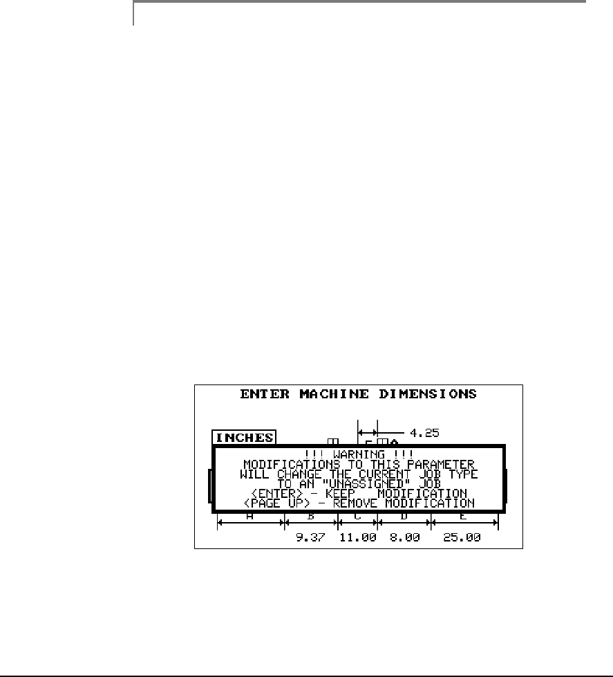
The following pop up box will be displayed if any fields are changed which
make the job an Unassigned job. Those fields are listed in the Unassigned
column on the previous page.
2

5-8 Using UltraSpec Alignment - General Overview
Note
If, for some reason, you do not want to assign a job to the data-
base, you always have the option of leaving it in the Unas-
signed Area. UltraMgr allows you to Load and Dump these
jobs to the analyzer the same way assigned jobs are handled.
5-9
General Overview
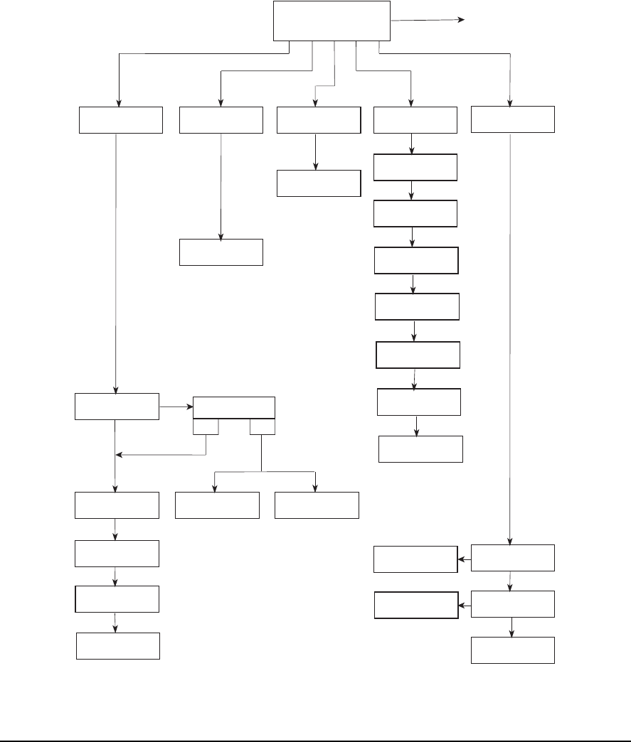
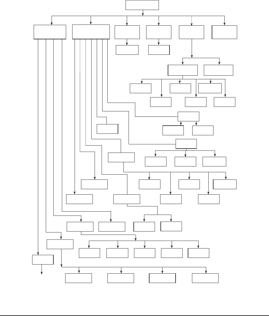
CSI Laser Menu Selections Map (page 1) –
Quick Spec Mode Off
1 2 3 4 5
Job Definition Alignment Data View Data Machine Moves
Additional Selections;
See Next Page
Soft Foot Results
Clear Complete Job
Machine View Clear Readings
and Notes
Thermal Growth
Clear Job
YesNo
Define Job
Laser Configuration
Acquire Data
Foot Pre-Check
Horizontal Move
Vertical Move
Reading Set Stored
Live Mode
Live Mode
Machine Dimensions
Offset & Angle
Graphics
Data Detail
Sine Fit Edit/View
4-Point Detail
Vertical Log
Horizontal Log
Data Stored
Pro Align Plus
5-10 Using UltraSpec Alignment - General Overview
CSI Laser Menu Selections Map (page 2) –
Quick Spec Mode Off
** Press Alt/Notes to enter
User Defined notepad
area from any place in
the application
*** Help screens
are available at
the appropriate
locations from
the various
program screens
(continued from
previous page)
Utility
1 2 3 4 Options Print
Screen Notes Help
Battery Test
System Setup
Delete Job(s)
Recall Job
Store Job
Communications
***
Feet/Base General
Observation Coupling/Shaft
Movement
Related
Load
Firmware
Set Modem
Command
Select
Applications
To Previous
Menu Map
Alt/Print
Screen
Print Screen
Alignment
Setup
Alignment *
Report
Alignment Notepad
(Pre-defined notes) User Defined **
(to add new notes)
* When the Laser History
Data screen is active,
you can also print a
Laser History Report
Quick Spec
Tolerances
Thermal
Growth
Review
Calibration
Foot Pre-Check
Laser Head
Status
Calculator
Mode
Predict Mode Face/Rim
Correlation
1 2 3 4 5 6 7
Address
Section
Read/Set
Address Set Analyzer
Address Review Current
Address
Method
All Jobs Individual
Job
Operational
Parameters
Date and Time
Units
Host PC
Load/Dump Communications
Setup Modem Connect
User
Defined All Notes
5-11
General Overview
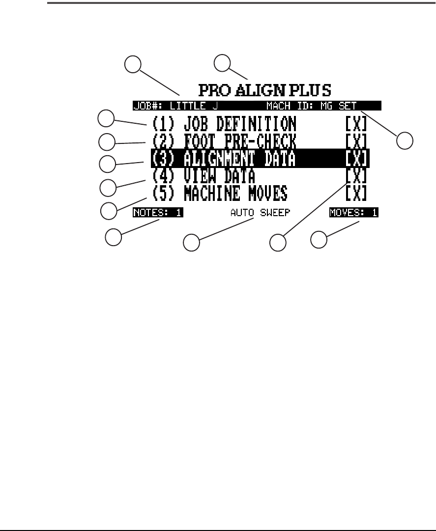
Main Menu Display
The Main Menu items are shown and described in the following section.
Main Menu Display
1.····Use this section to complete all items necessary to document the job
properly.
2. ···Allows you to locate feet that are causing machine problems
(including relative severity).
3. ···Section where alignment data is acquired.
4. ···Displays graphical representation of the present alignment condition
in offset and angle.
5. ···Calculates required machinery moves, both vertical and horizontal.
A real time machine move is provided for machine positioning.
6. ···Program header – identifies program as Pro Align Plus.
7.····Total number of notes that are stored with the Current alignment job
(up to 40).
8. ···An X appears after each function that has been properly performed.
1
2
3
4
5
6
789
10
12
11

5-12 Using UltraSpec Alignment - General Overview
9.··· Shows the number of machine moves that have been stored in the
Current alignment job (up to 20).
10. · The job number as defined in the Job Definition section.
11. · The Machine being aligned.
12. · Data collection method currently being used.
5-13
Job Definition
Job Definition
Define Job
To bring up the Define Job screen, select the Job Definition section on the
Main menu.
Define Job Screen
Use the Up Arrow or Down Arrow to highlight the following portions of
the Define Job menu.
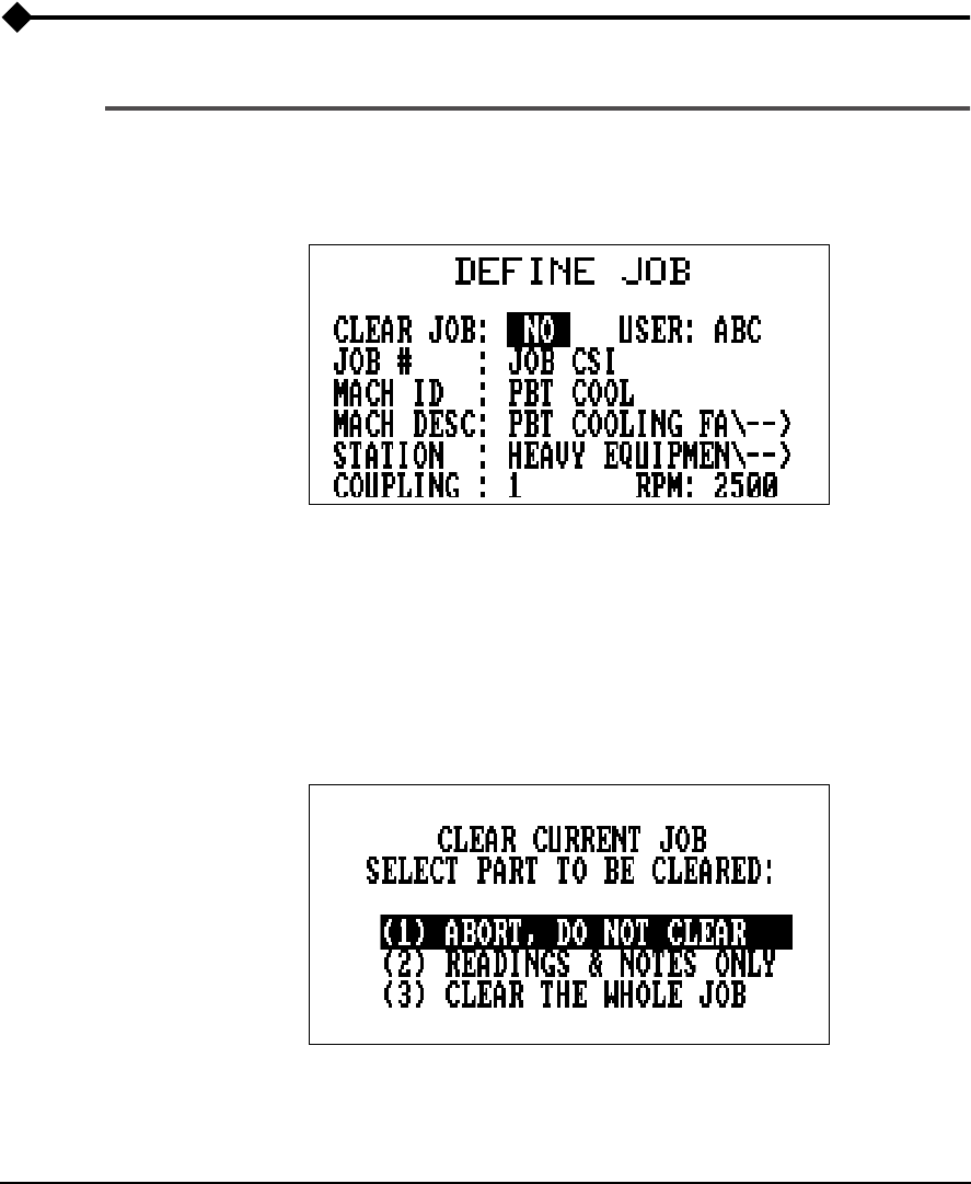
Clear Job:
You can erase part or all of the Current job shown on the Define
Job menu. Use any numbered key to toggle to “Yes”; press Enter and a
screen showing three options will be displayed.
Clear Job Options

5-14 Using UltraSpec Alignment - General Overview
Press the Up Arrow or Down Arrow to highlight one of the following three
selections. Press Enter to accept.
(1)·· Abort, Do Not Clear – returns you to the Define Job menu with no
changes to the job.
(2)·· Readings & Notes Only – causes all job alignment reading sets (up to
20) and notes (up to 40) to be erased. The information in the Job
Definition section will remain unchanged. You will be returned to the
Define Job menu after the Readings have been cleared.
If a job is received from UltraMgr and the only things changed during the
alignment job are the alignment readings and notes, the new job will be
dumped directly back to the proper Station and Machine.
(3)·· Clear the Whole Job – causes all alignment readings, notes, machine
moves, machine distances, and job definition fields to be erased. You
will be returned to a blank Define Job menu after the Job has been
cleared.
Note
The menu items Job #, Mach ID, Mach Desc, Station, and
Coupling are used for documentation purposes and for identi-
fication within UltraMgr.
User:
An alphanumeric, 3-character field to identify who performed the
alignment job (see “Alphanumeric Keys” on page 2-15). Normally, it will be
the user’s initials.
Job #:
You can select up to 10 characters to name the job (job name must
be furnished to save the job – a job cannot be saved with a blank Job#). The
Job# gives the job a unique identification; it can be tied to a work order
number, etc.
If the job is defined within the analyzer, it will be dumped to UltraMgr as
an Unassigned job. After the dump is complete, the job should be assigned
to its machine. The Mach ID, Mach Desc, and Station will be modified to
match their assignment within UltraMgr.
If no machine or station exists (in the UltraMgr database), they can be cre-
ated after the job has been dumped. You can then complete the job assign-
ment.

5-15
Job Definition
Note
If the job is defined within UltraMgr, the Mach ID, Mach Desc,
Station and Coupling cannot be modified within the analyzer.
Mach ID:
- Up to 10 characters can be used to define a Machine ID code
for the machine being aligned.
Mach Desc:
- By pressing any key on the keypad (except Page Up or Alt),
the highlighted block can be expanded. Up to 28 characters can be used to
describe the machine being aligned. Press the Up Arrow or Down Arrow
to go to the next section of Define Job (characters off the screen will not be
lost).
Station:
- Press any numbered key to expand the highlighted block. Up to
32 characters can be used to describe the station where the machine is
located.
Coupling:
- If machinery being aligned has more than one coupling, use
this section of Define Job to number them. Each coupling should have its
own unique number. An example would be a machinery train consisting of
a motor, a gearbox, and a compressor. The coupling between the motor
and gearbox should be 1 and the coupling between the gearbox and com-
pressor should be 2. Positive numbers up to 10 can be entered.
RPM:
- A unique RPM exists for each coupling that is entered. If you have
a variable speed machine, enter the highest RPM at which the coupling will
be operated. Also, if a coupling design has shafts operating at different
speeds, enter the larger of the two. This parameter is used to establish align-
ment tolerances.
When finished, press the Enter key to continue.
5-16 Using UltraSpec Alignment - General Overview
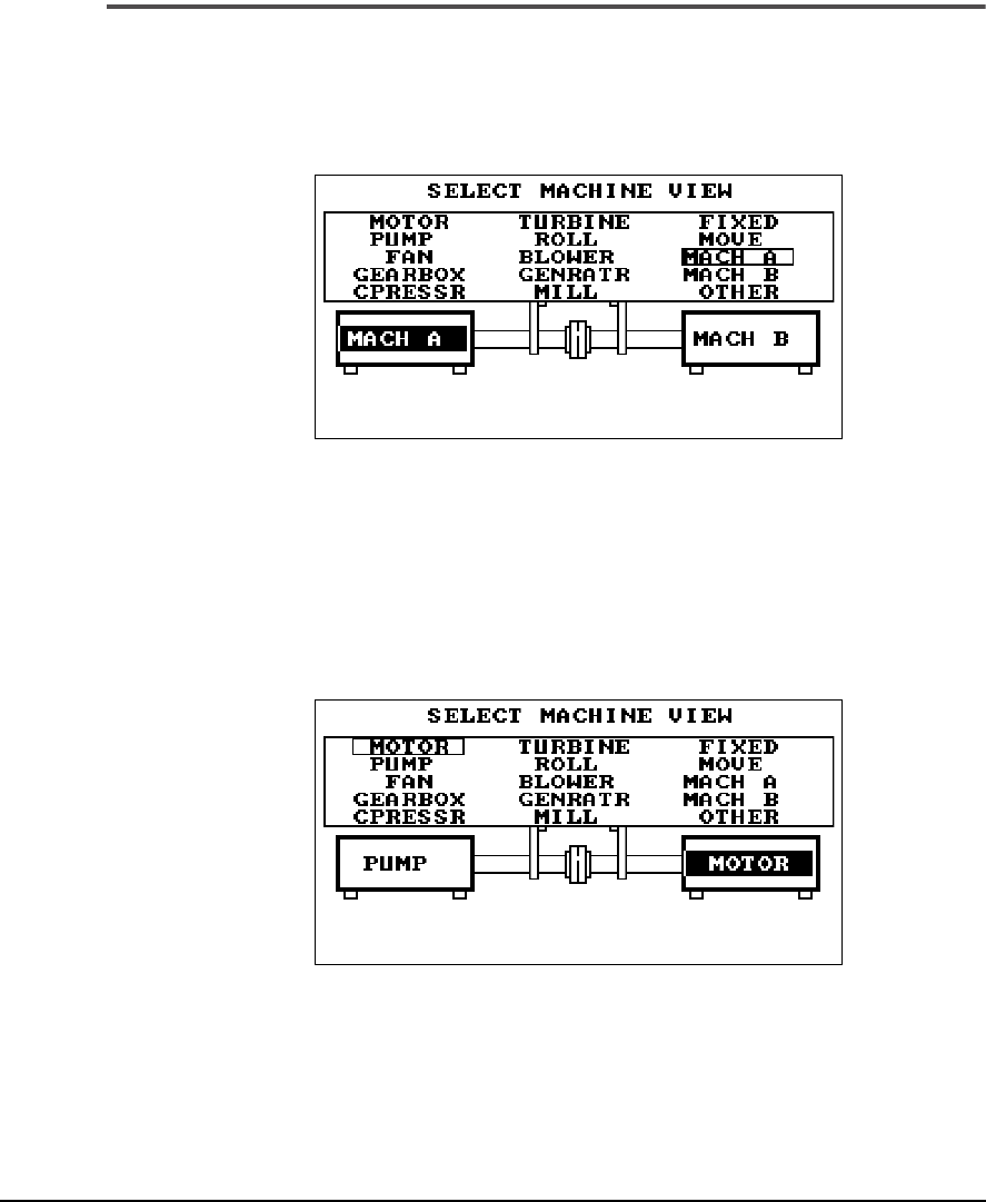
Machine View
Use the following screen to define how the machines will be viewed during
the alignment job. In this view, the two machines are connected by one
coupling.
Machine View Screen
The machines should be named according to how they are installed
relative
to the location where the user will view the machines
. Choose the appropriate
name with the Up/Down arrow keys and Left/Right arrow keys. Press
Enter to accept the left machine. Proceed to the right machine and repeat
the process. Then, press Enter to move to the next screen.
5-17
Job Definition
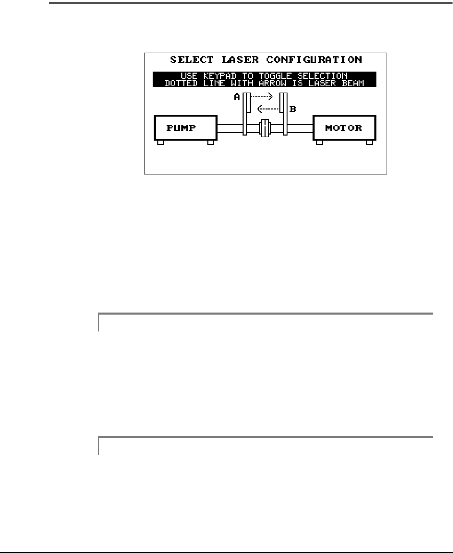
Laser Configuration
It does not matter which sensor head is put on which machine, however,
the analyzer must know each head’s location. Use any keypad key to toggle
from one configuration to the other. The arrows must be set to match the
directions that each laser will transmit, i.e., the arrows must represent the
actual laser directions by pointing away from the small circle and toward
the red target. Press Enter to accept the configuration.
Caution!
Selecting the proper configuration for the laser heads is extremely
important! If the setting is wrong, all of the machine move calculations
will be incorrect.
For the Model 8215/8225, A and B are marked on the face plate of the laser
head.
Note
The program automatically knows whether Model 8215 or
8225 laser heads are being used.
5-18 Using UltraSpec Alignment - General Overview
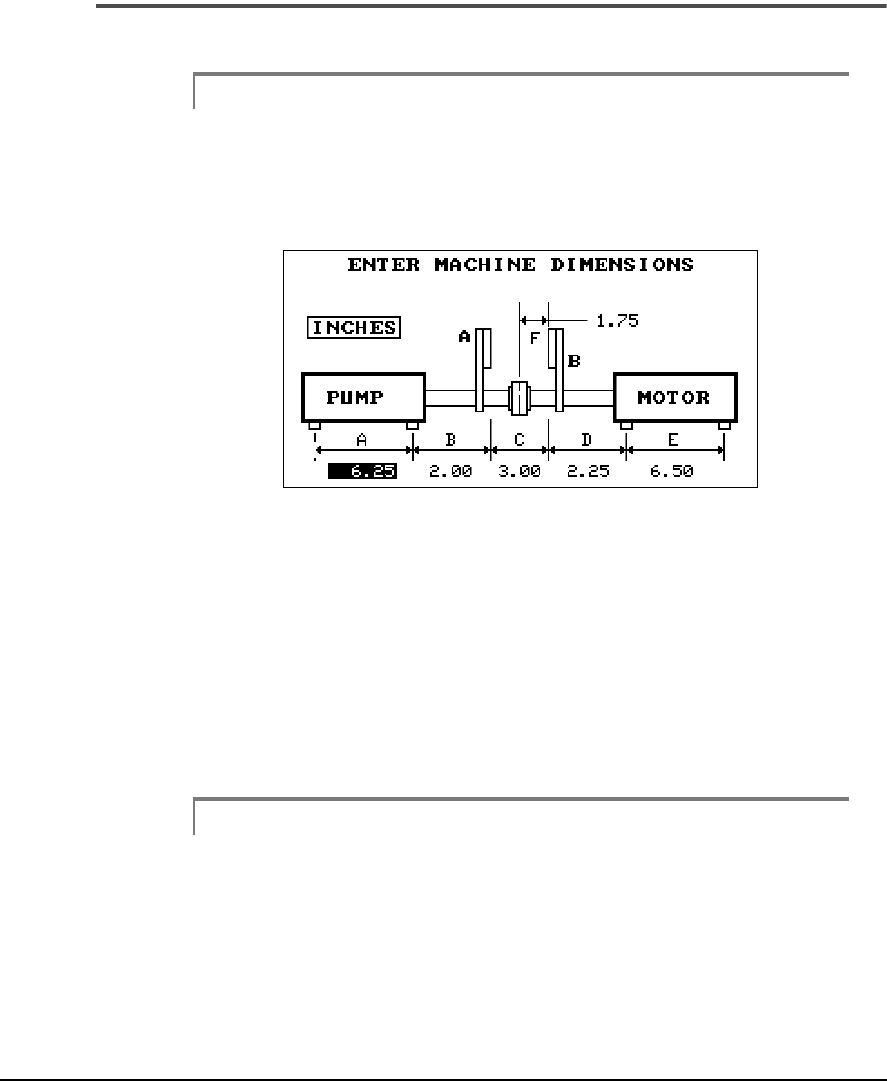
Machine Dimensions (A through F)
Note
This section assumes that the fixtures are set up to the point
that the sensor heads are mounted.
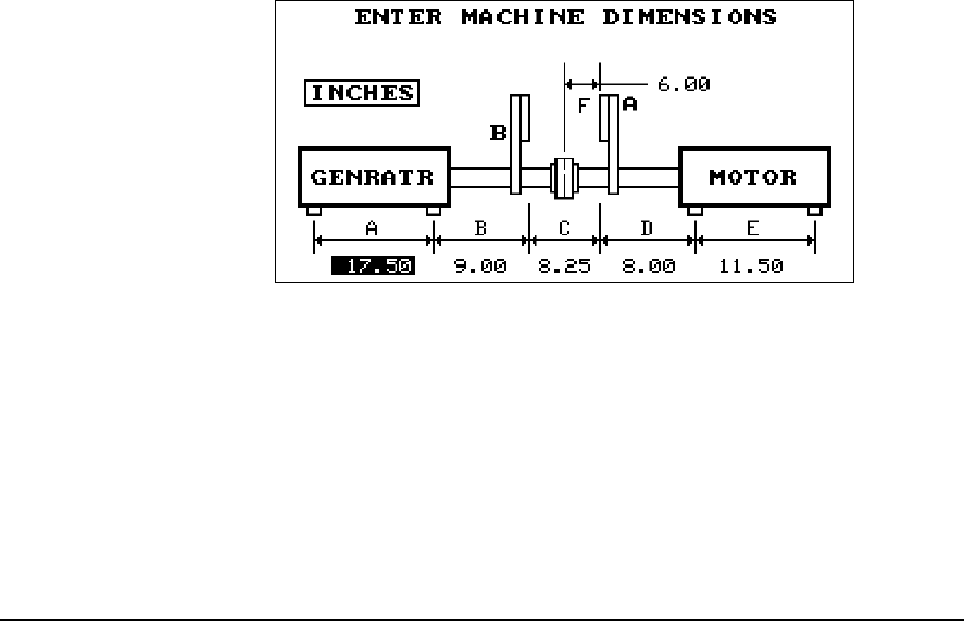
After accepting the configuration, the following screen will appear.
Machine Dimensions (A) Screen
Measure all of the dimensions to the nearest 1/8 inch (3 mm) with the
exception of dimension C. Dimension C should be measured to the nearest
1/16 inch (1.5 mm). Refer to “Entering Fractions (Alignment Applications
Only)” on page 2-17 for instructions on entering fractions into the system.
Use the Up/Down arrow keys to select the field you want to modify; press
Enter to accept the entry. Refer to the following table for a description of
each dimension.
Note
The dimensions are the same for both the Model 8215 and
8225 laser heads.

5-19
Job Definition
Note
With large equipment, you may need to drop a plumb bob
from the sensor head to measure these dimensions accurately.
Dimension Measurement Description Measure to
Nearest
A Center of outboard foot to center of inboard foot of the machine on
the
left
.1/8 inch
(3 mm)
B
Center of inboard foot on the
left
machine to the sensor
head
face
on the
left
machine. To enter a measurement for a foot that falls
inside the laser face, place a negative sign (–) in front of it.
1/8 inch
(3 mm)
C
Measure from the
inside
face
of one sensor head to the
inside
face
of the other sensor head. 1/16 inch
(1.5 mm)
D
Center of inboard foot on the
right
machine to the sensor
head
on
the
right
machine. To enter a measurement for a foot that falls
inside the laser face, place a negative sign (–) in front of it.
1/8 inch
(3 mm)
E
Center of outboard foot to center of inboard foot of the machine on
the
right
.1/8 inch
(3 mm)
F
From
right
sensor head to
center
of coupling or, to the location
where offset tolerances are measured (this is not required for
jackshaft tolerances).
1/8 inch
(3 mm)
5-20 Using UltraSpec Alignment - General Overview
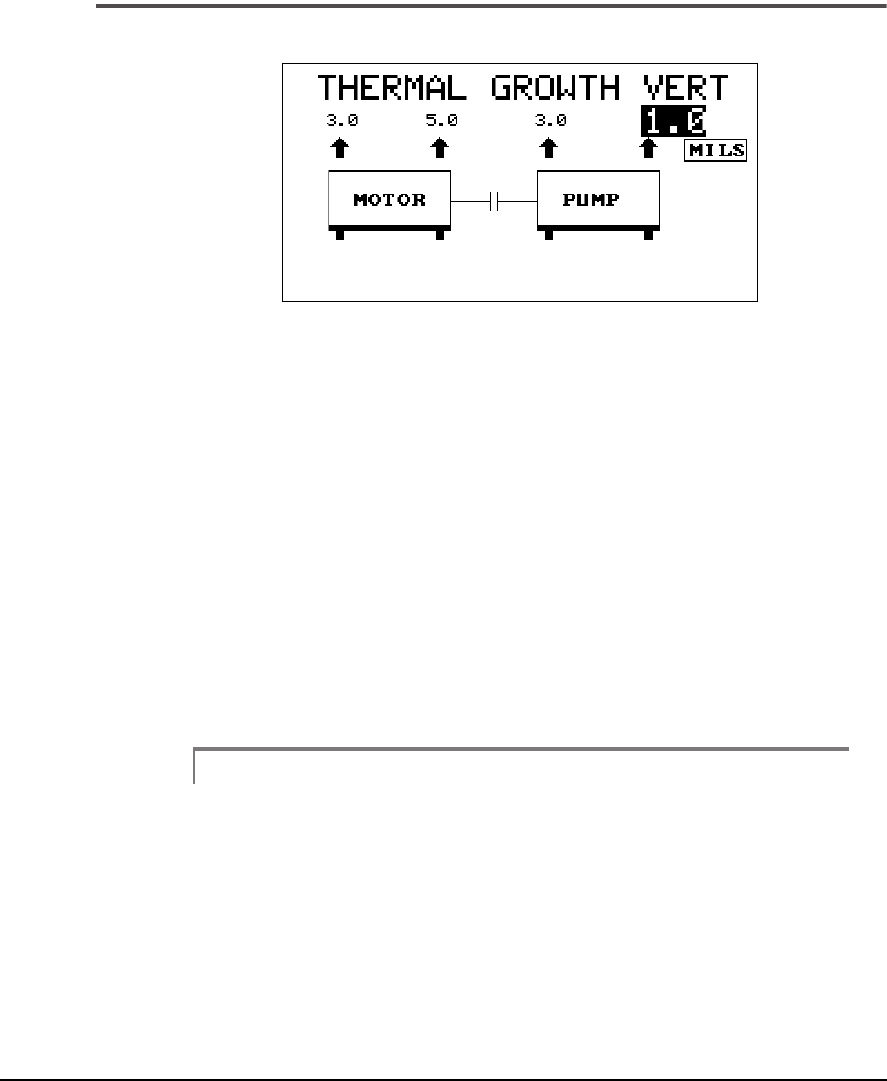
Thermal Growth, Vertical
Thermal Growth (Vertical) Screen
This screen shows a side view of the coupled machinery. The amount of
vertical thermal growth that both machines will experience during opera-
tion can be expressed in either mils or millimeters (mm). Thermal growth
values should correspond to the amount each shaft will move in the vertical
direction directly above each foot. If thermal growth is negligible, enter
zeroes. The range of values that can be entered are -250 to 250 mils and
-6.35 to 6.35 mm.
Press the Up Arrow or Down Arrow to toggle between the growth values.
If one or both machines actually experience a downward growth during
operation, negative numbers should be used. Press the Enter key to accept
the vertical readings; then, the Thermal Growth Horizontal screen will
appear.
Note
The Thermal Growth screens only appear in the Job Definition
section if Thermal Growth is set to Yes in the Options, Align-
ment Setup menu. Refer to “Alignment Setup” on page 3-6 for
more information.
5-21
Job Definition
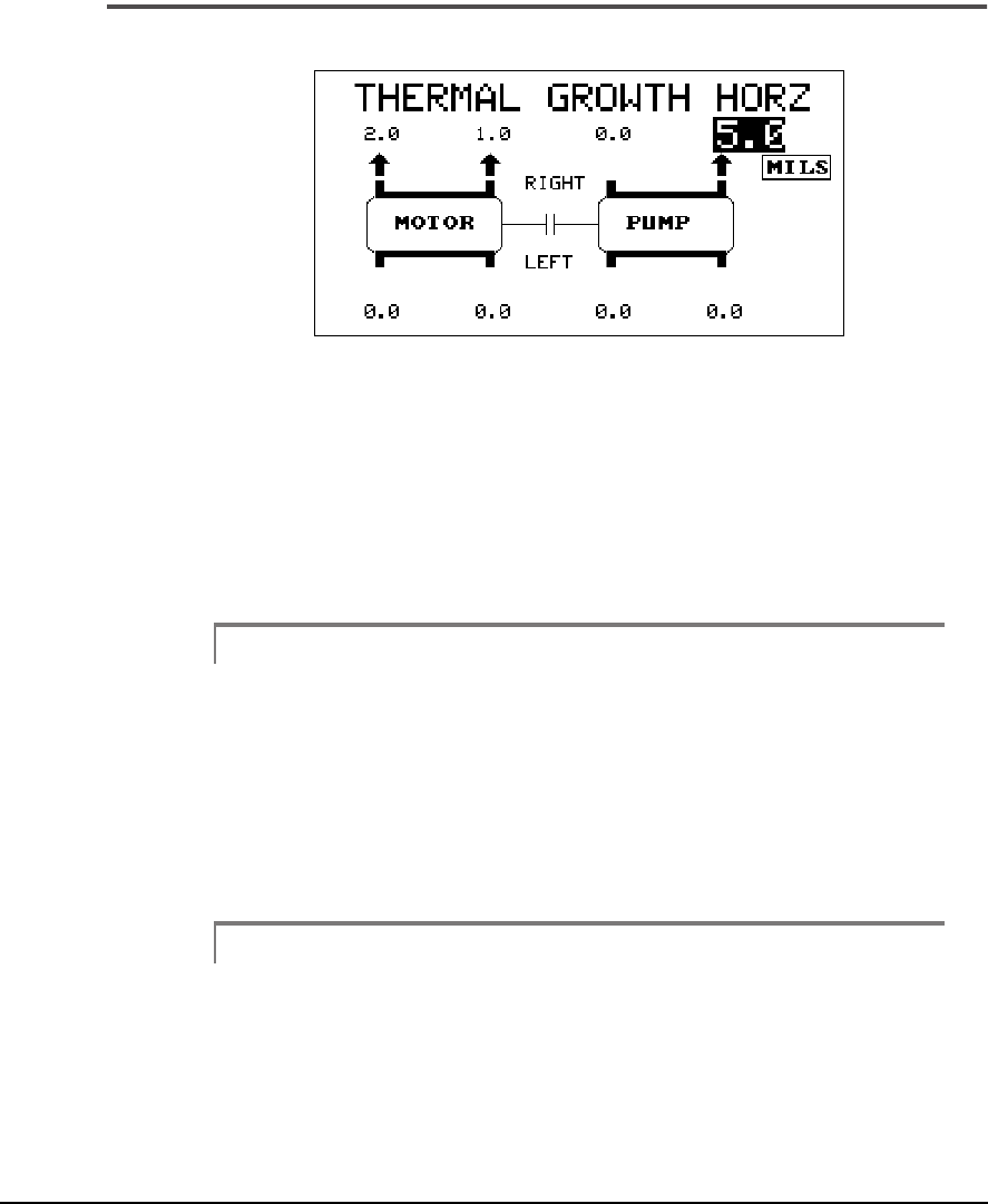
Thermal Growth, Horizontal
Thermal Growth (Horizontal) Screen
This screen shows a top view of the coupled machinery. Horizontal thermal
growth can be entered in this top view of the coupled machines. Thermal
growth values (mils or mm) should correspond to the amount each shaft
will move at each foot. If thermal growth is negligible, enter zeroes at all
locations. One entry field at each set of feet must be zero. The range of
values that can be entered are 0 to 250 mils and 0 to 6.35 mm.
Note
If negative horizontal thermal growth numbers are entered, the
system will change them to positive numbers.
The Up Arrow will scroll from the right side to the left side at each set of
feet, then onto the next set of feet to the right. The Down Arrow will scroll
in the opposite direction. Press the Enter key to accept the values; you will
then be returned to the Main menu.
Note
Thermal Growth values measured by the UltraSpec Thermal
Growth application can be transferred to the UltraSpec
ProAlign Plus program. Refer to the UltraSpec Thermal
Growth User’s Manual for more information.
5-22 Using UltraSpec Alignment - General Overview
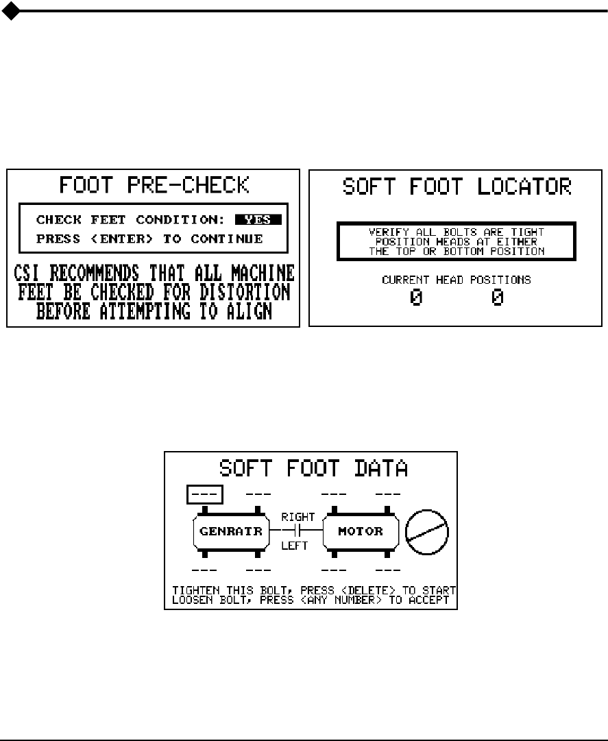
Foot Pre-Check
When Foot Pre-Check is selected (from the main menu) and the Job Defi-
nition screen is completed, a screen similar to the one below on the left will
be displayed. The screen that is displayed depends on the type of Foot Pre-
Check selected (Soft Foot or Frame Distortion Index [FDI]). For more infor-
mation, see the Appendix heading, “Foot Pre-Check Types” on page -1.
Use the Enter key to move to the Soft Foot/FDI Locator screen (on the
right). Ensure that the sensor heads are at the top (as shown) or, at the
bottom position (180°). After verifying that all hold-down bolts are tight,
press Enter to proceed to the Soft Foot/FDI Data screen shown below.
Use the Up/Down arrow keys to select the foot to be checked. In the screen
above, the right outboard foot of the generator has been selected. Press
Delete to start.
5-23
Foot Pre-Check
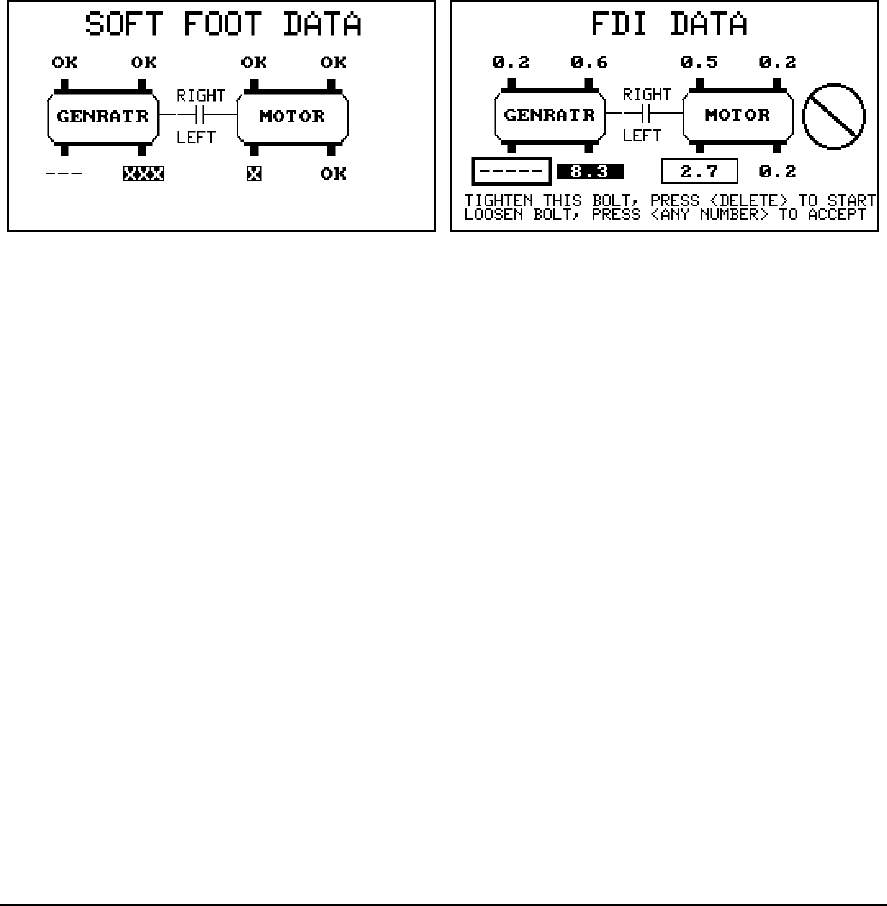
Loosen the hold-down bolt and wait for the dial to stop. Press any number
key to accept that value; the cursor will move to the next foot. Retighten
the bolt and proceed to the next foot. To remove results (clear data at a
single foot) and acquire new data, press Delete. To remove results at all feet
(clear data at all feet), press Alt/Delete.
After all feet have been checked (CSI recommends that you always check
all feet), press Enter and the data will be evaluated. The data is evaluated
based on the type of Foot Pre-Check being used. If Soft Foot is selected, the
data is evaluated as follows:
• “-----” – no measurement was made for this foot
• “OK” – the measurement to determine Soft Foot is within the speci-
fied tolerance
• “x” – the measurement is from 1 to 2 times the specified tolerance
(1x tolerance < measurement ≤ 2x tolerance)
• “xx” – the measurement is from 2 to 3 times the specified tolerance
(2x tolerance < measurement ≤ 3x tolerance)
• “xxx” – greater than 3x tolerance
This method does not display a number as the machine is being checked
for soft foot (to prevent you from mistaking this number for a shim correc-
tion).

5-24 Using UltraSpec Alignment - General Overview
If FDI is selected, the data is evaluated by default as follows:
• “-----” – no measurement was made for this foot
• “No Box” – excellent condition (less than 2.0)
• “Clear Box” – acceptable condition (between 2.0 and 3.0)
• “Dark Box” – out of tolerance (greater than 3.0)
These tolerances can be changed in UltraMgr and transferred to the UltraSpec.
Warning!
The numbers displayed are not the required correction
shims for this foot. Soft Foot corrections frequently
require wedge shaped arrangements of shims to be
installed. However, the actual thickness and shape of the
Soft Foot correction must be determined by using a feeler
gauge.
Note
For more information about Foot Pre-Check, see Appendix
heading “Foot Pre-Check Types” on page -1
Note
Remember that all this data is dumped to UltraMgr. Help mes-
sages are available if needed.
5-25
Alignment Data
Alignment Data
This function, available from the main alignment menu, allows you to make
the raw measurements needed for the calculation of the relative positions
of the shafts. This section gives a brief overview of the available data collec-
tion modes. The next chapter gives an in-depth look at each mode.
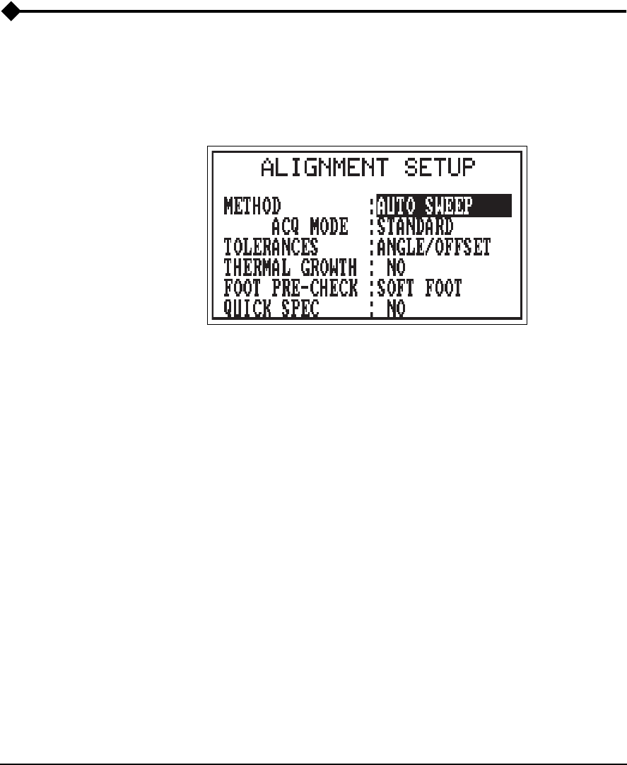
Method: to provide data acquisition for varying applications, circum-
stances, and preferences, a number of different data collection methods are
provided. The method to be used is selected by entering the Alignment
Options menu accessed by pressing the Options key and selecting Align-
ment Options. These include:
•Auto Sweep – data is automatically acquired while the shaft is
rotated. The arc of rotation can vary from as little as 45° to a full 360°
(one revolution). This mode is especially useful when the 4 point
measurement technique is impractical or when inconsistencies in
shaft position exist at points in the rotation. Averaging mode allows
many revolutions, see details on page 6-7.
•Manual Sweep – data is measured each time the laser heads are in
alignment and the number keypad is pressed. Data from up to 36
positions may be recorded. This mode is especially useful for per-
forming uncoupled or non-rotational alignments. Functions similarly
to the Auto Sweep mode except that the laser heads, or shafts, are
stopped at each position where data is to be taken and a key pressed
to store a reading.

5-26 Using UltraSpec Alignment - General Overview
•4 Point Auto – the four point automatic mode is a more traditional
style of acquiring data for alignment. The laser heads are mounted
on a shaft, and the shaft is then rotated so that data can be taken when
the laser heads are at the 12 o’clock (0 or 360°), 3 o’clock (90°), 6
o’clock (180°), and 9 o’clock (270°) positions. The readings are con-
tinuously averaged whenever the laser heads are at one of these posi-
tions and automatically recorded when the shaft is rotated to the next
position. The averaging process reduces variation from jitter due to
background vibration or from slight changes in the angular position
of the heads.
•4 Point Manual – similar to the 4 Point Auto mode except that the
user has complete control over when data is acquired and which of
the four measurement positions it will be used in. This mode is useful
when the machinery is not mounted in a true horizontal orientation,
so that the inclinometer is not effective or when the clock positions
relative to vertical and horizontal base movements of the machine are non-
standard.
•Straightness – allows the laser heads to be used to collect elevation
readings for surface profile analysis.
•Dual Pass – functions similar to the Auto Sweep mode except data
is automatically acquired as each laser head passes by each other.
This mode, like Manual Sweep, is useful for performing uncoupled
or non-rotational alignments.

5-27
Alignment Data
Data Quality
When using Auto Sweep, Manual Sweep, or Dual Pass a sine curve is fit to
the data points to determine what the projected data would be at each of
the clock positions mentioned above in the 4 Point Auto method. If the fit
of the curve to the data points is marginal, then the data can be automati-
cally conditioned to improve the sine fit. The resultant fit may be viewed
and can be manually conditioned if desired. This procedure is discussed in
the application chapter. If the analyzer is unable to condition the data suit-
ably, then a message “UNFIT DATA” will appear on-screen warning the
user to retake data or change data collection methods. There is always some
variability introduced into data due to shaft clearances, bearing faults, base
deterioration, etc. If this variability becomes significant compared to the
amount of misalignment, it may become necessary to use a 4 Point or
Manual Sweep Method to acquire data. Changing methods does not
require the job to be redefined. Merely select a new method from the Align-
ment Options menu and retake the last set of data.
When using any 4 point method the data is always checked for validity. In
theory, subtracting any third measurement from the sum of two opposing
measurements will give the value of the 4th measurement (the one opposite
the third measurement). For example, add the left and right measurements
together, then subtract the top measurement. The results should approxi-
mately equal the value of the bottom measurement. If this comparison
varies by more than 20%, a message will be displayed warning of a “Data
Validity Error, Reading Error Above 20%”. When this happens you should
retake the last readings to check for accuracy, before proceeding. There is
always some variability introduced into data due to shaft clearances,
bearing faults, base deterioration, etc.
5-28 Using UltraSpec Alignment - General Overview
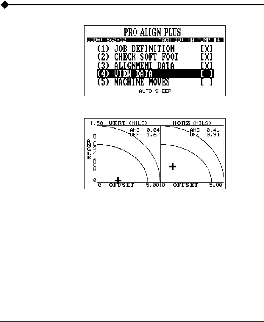
View Data
Dual Tolerance Plot
After acquiring data, the view data function allows you to check the accept-
ability of the current alignment. Both the vertical and the horizontal rela-
tionships are plotted as well as the calculated values for angle and offset or
left angle and right angle. The bold crosshair shows the current condition,
whereas a faint crosshair is drawn to show the previous position. Use the
Up/Down arrow keys to change the plot scaling if needed. The area under
the lowest arc is the excellent range. The area under the higher arc and
above the lower arc represents the acceptable range. Pressing Enter will
return the user to the main menu.

5-29
View Data
Note
If more than one set of alignment data has been acquired, the
last two data sets acquired will have their current conditions
displayed on this screen. The last data set will have its current
condition represented by the bold crosshair while the previous
data set will have its current condition represented by a
crosshair that isn’t bold. Individual plots displaying all align-
ment data sets acquired are available. Refer to “Additional
Data Detail” on page 5-34 for details.

5-30 Using UltraSpec Alignment - General Overview
Tolerances
The amount of offset and angular misalignment displayed is based upon the
last full set of alignment readings. All shaft misalignment is a combination
of offset and angular misalignment (see “Alignment Application Notes” on
page 8-3). This screen breaks down the misalignment into each component.
The amount of each type of misalignment is shown for both the horizontal
and vertical directions (for horizontal machines). These values are only used for
tolerances therefore, only absolute values are used (no negative signs).
Standard
The combination of offset and angle is a direct indication of the alignment
condition. Optimum alignment occurs when offset and angle are zero. In
most cases, that degree of accuracy is not practical. For that reason, toler-
ances are used to set an achievable goal. CSI’s recommended tolerances
(referenced to RPMs) are listed in the table below.
Values in the table are assumed to be pure offset or pure angle. However,
in most cases, you will have a combination of the two and tolerances should
account for this combination.
For example, for an 1800 RPM machine which has 3.5 mils of pure offset
misalignment, the alignment is in the acceptable range. Or, if it has 0.80
mils/inch of pure angular misalignment, the alignment is acceptable. How-
ever, if the remaining misalignment is a combination of 3.5 mils offset and
0.80 mils/inch angular, the misalignment is not as good, and should be con-
sidered out-of-tolerance.
Speed
(RPM)
Excellent Acceptable
Offset
(mils) Angle
(mils/inch) Offset
(mils) Angle
(mils/inch)
< 500 5.0 1.5 6.0 2.0
500 - 1250 4.0 1.0 5.0 1.5
1250 - 2000 3.0 0.5 4.0 1.0
2000 - 3500 2.0 0.3 3.0 0.5
3500 - 7000 1.0 0.25 2.0 0.3
> 7000 .5 0.2 1.0 0.25
5-31
View Data
Plotting the condition as a single point on an X-Y graph provides a true
indication of the alignment status.
The offset and angle information is intended to be used as an alignment tol-
erance only (to determine how close the alignment is based upon the last
set of alignment readings); do not use these data to align the machines. For
this reason, offset and angle are always displayed as positive numbers.
The curves at the lower left are the tolerances to shoot for. Depending on
RPM, they can be modified in UltraMgr and then transferred to the ana-
lyzer.
The alignment condition (with respect to the tolerances) can be monitored
by observing the tolerance target during the live move. The bullseye means
you are within the excellent tolerance range. The middle band means you
are within the acceptable range, but outside the excellent range. The out-
side band means you are within 1x - 2x of the acceptable tolerance.
The example above shows that the alignment condition is in the acceptable
range.
Tolerance
Target
5-32 Using UltraSpec Alignment - General Overview
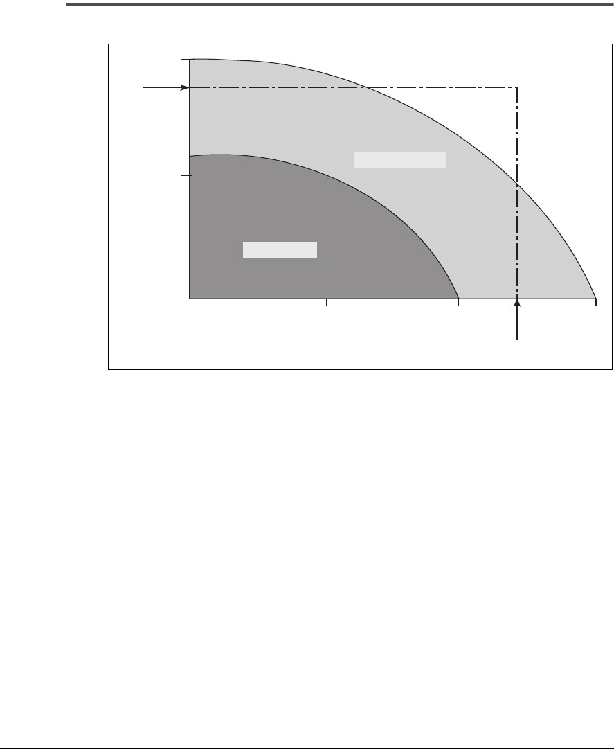
Tolerance Example
Tolerance Chart (2000 to 3500 RPM)
The chart above shows the Angle and Offset for a machine that operates at
2000 – 3500 RPM plotted together. A pure angle reading of 0.45 Mils/Inch
and a pure Offset reading of 2.5 Mils are marked by the arrows. These read-
ings are clearly in the acceptable range when looked at individually. How-
ever, look what happens when these two “acceptable” reading are plotted
together. The two lines connect outside the acceptable range. This illus-
trates the importance of looking at the Offset and Angle together when
establishing specified tolerances.
Excellent
Acceptable
Offset (mils)
Angle (mils/inch)
12 3
0.25
0.50
5-33
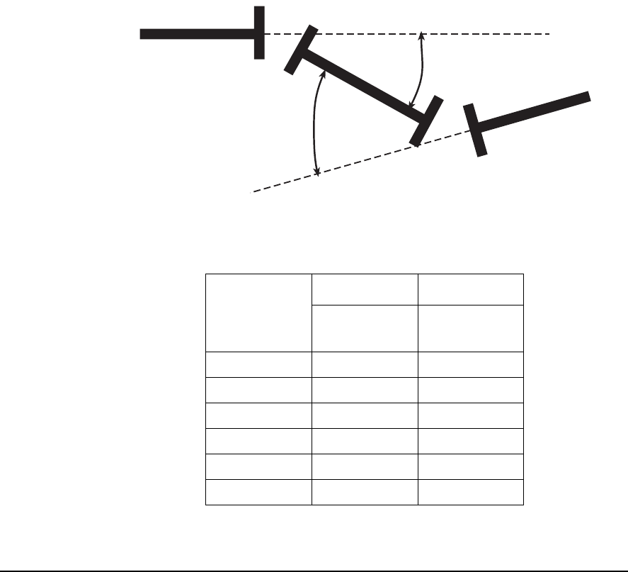
View Data
Jackshaft
One of the biggest advantages in using a laser system is the ability to align
over long distances (> 20”). The further apart the sensor heads are
mounted, the less practical it is to use the Offset and Angle Tolerances. In
those cases, the Jackshaft Tolerances should be used. This method measures
the two angles (α and ß) as shown in the figure below. The combination of
these two angles are laid out on a graph similar to the offset and angle
graphic. When the angles are within tolerance, the cursor will be in the
Excellent or Acceptable range.
CSI’s recommended tolerances are listed in the following table.
3
Speed
(RPM)
Excellent Acceptable
Angle
(mils/inch) Angle
(mils/inch)
< 500 1.0 2.0
500 - 1250 0.9 1.8
1250 - 2000 0.8 1.6
2000 - 3500 0.6 1.2
3500 - 7000 0.4 0.6
> 7000 0.2 0.3
ß
α
5-34 Using UltraSpec Alignment - General Overview
Additional Data Detail
4
For users who want to view the acquired data in more detail, pressing the
Page Down key when the dual plot is displayed (see “Dual Tolerance Plot”
on page 5-28) will access additional screens.
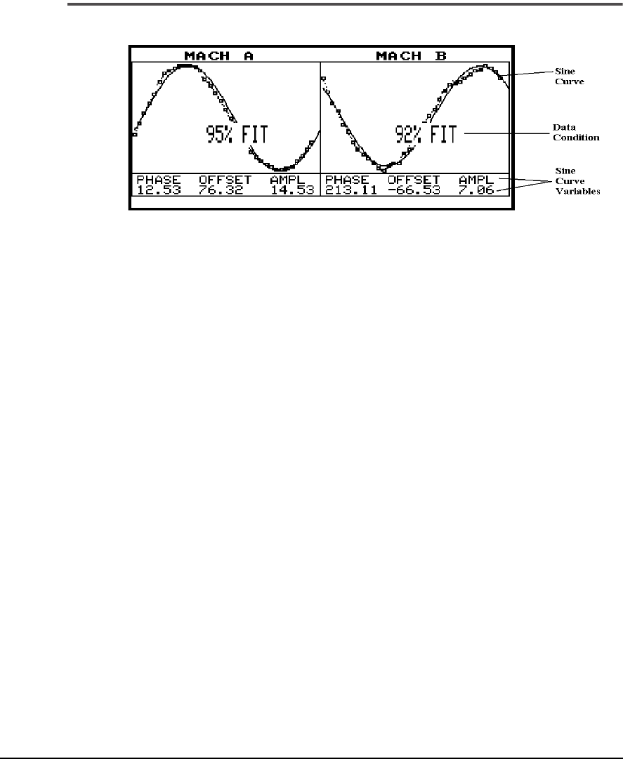
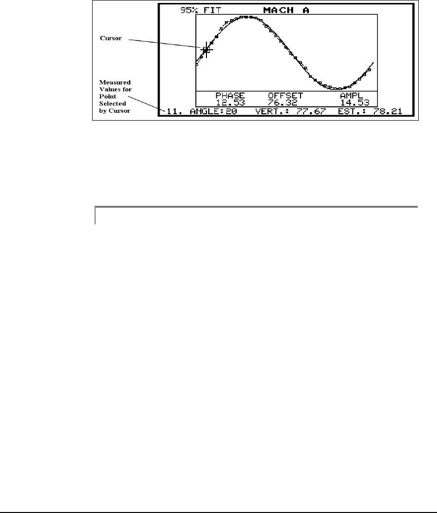
Sine Fit – When Dual Pass or one of the sweep methods is used, the dual
Sine Fit screen is displayed first. Points which are shown as boxes have been
included in the fit to the sine curve. How well these points fit the sine curve
is given as a percentage. Points which are shown as a single dot have been
excluded from the fit.
Press the Alt/Left Arrow key to edit the left sine curve, and press the Alt/
Right Arrow key to edit the right sine curve. Press the Left or Right Arrow
key to move the cursor to individual points (one point at a time). Use the
Up or Down Arrow key to move the cursor to individual points 10 points
at a time. The measured values for the point selected by the cursor is shown
at the bottom of the plot. An asterick (*) displayed next to the point number
indicates that point has been excluded or deleted from the fit.
A point may be excluded from the fit by placing the cursor over it (using
the Arrow keys to position the cursor) and pressing the Delete key. The box
will become a point indicating it is not considered in the curve fit. Press the
Alt/Delete key to undelete all deleted points and refit the sine curve to its
original condition. A previously excluded point may be included by
placing the cursor over the point and pressing the Insert key. Each time a
point is removed or added the sine fit will be recalculated. Press the Alt/
Left Arrow key and the Alt/Right key to move the cursor between the first
and last points.
5-35
View Data
5
CSI does not recommend making moves based on sine fit percentages of
less than 70%. Although sine fits of 70 to 85% can be used, CSI recom-
mends another set of readings be made to try and improve the accuracy.
Sine fits above 90% provide the highest repeatability.
Note
Although up to 180 data points can be acquired, not all the data
points are fit to the sine curve. The data points fit to the sine
curve (up to a maximum of 36) are selected so they are evenly
spaced over the acquired sweep area. Therefore, when editing
a sine curve no more than 36 data points can be inserted.
5-36 Using UltraSpec Alignment - General Overview
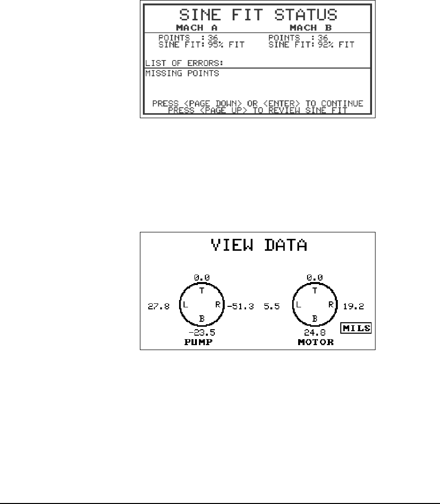
From the dual Sine Fit screen, press Enter to leave this screen and display
the Sine Fit Status screen.
6
Sine Fit Status Screen
Sine Fit Status – this screen summarizes the number of points used, per-
centage of fit, and lists factors (errors) which could be corrected to improve
the data. From the Sine Fit Status screen, press Enter to leave this screen
and display the View Data Screen.
7
View Data Screen
5-37
View Data
4 Point - View Data – this screen appears first if using the 4 point methods
or immediately following the sine fit information if using the sweep
methods. Data cannot be edited and is simply provided for the conve-
nience of those who are accustomed to recording the data in this manner
or who wish to use this data to perform a graphical solution on paper. To
see the “raw data,” (the position of the beam on each target) press the 0 key.
To return the top reading to zero, press the 0 key again. Press Enter to leave
this screen.
8
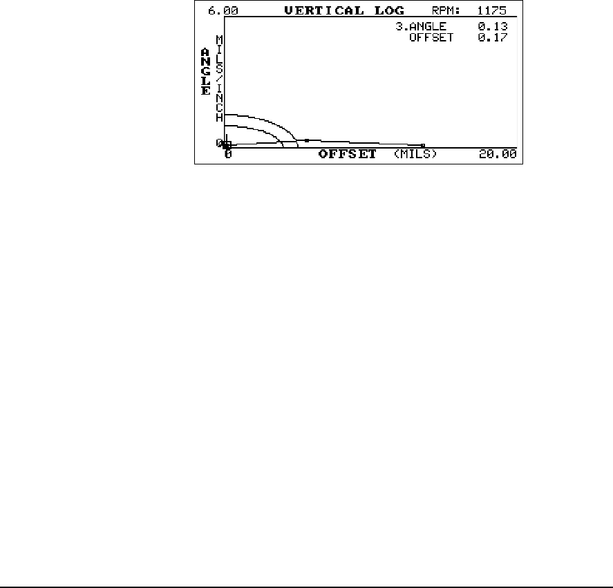
Vertical Log – this is an enlarged version of the vertical plot shown on the
dual plot. In addition to the misalignment based on the two most recent
alignment measurements, all previous measurements are shown. The Left/
Right arrow keys may be used to move a cursor to each plotted point. The
corresponding angle and offset will be displayed. The Up/Down arrows
can be used to change the overall plot scaling.
To view the Acceptable and excellent tolerances press the Alt and Page Up
keys. To return to the optimum scale press the Alt and Page Down keys.
5-38 Using UltraSpec Alignment - General Overview
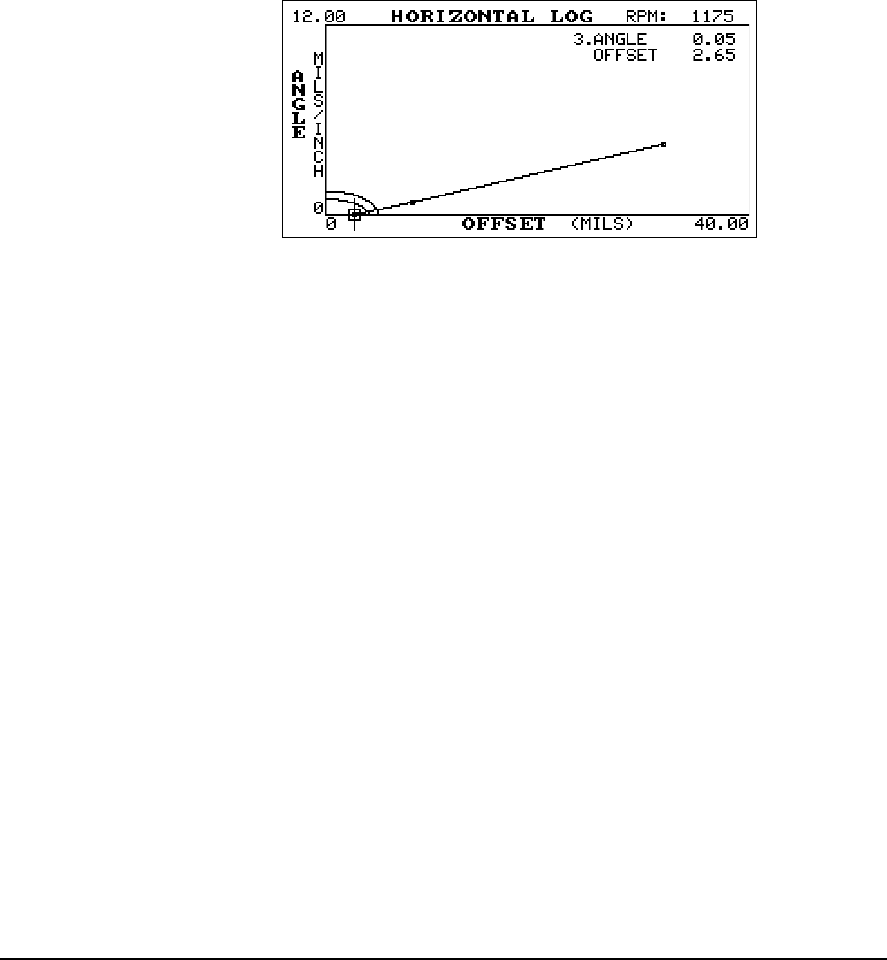
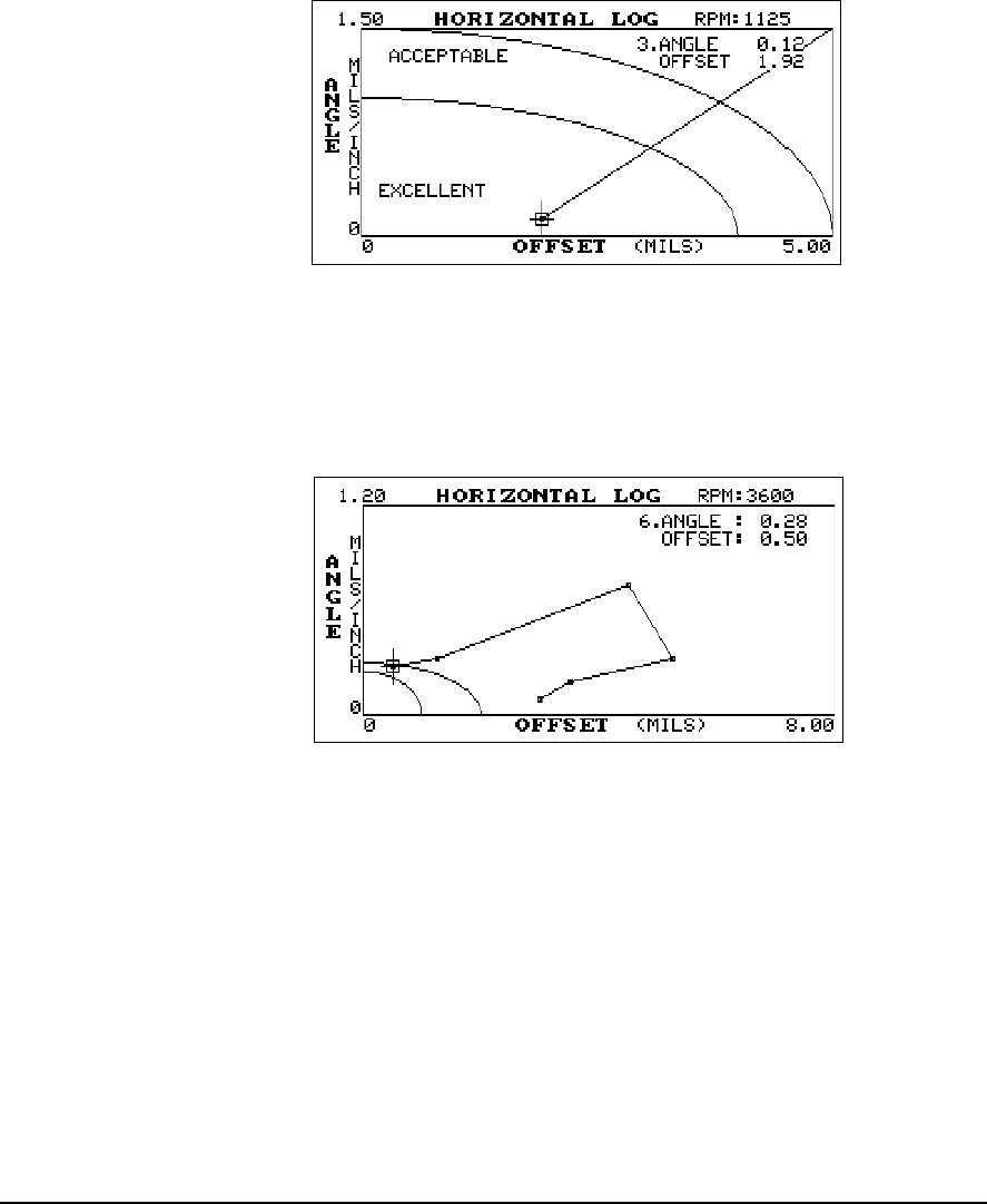
Horizontal Log – press the Enter key to exit the vertical log and display
the horizontal. The arrow keys perform the same cursor and scaling func-
tions as for the vertical plot. Pressing Enter at this screen returns to the pro-
gram’s main menu.
9
5-39
View Data
10
To view the Acceptable and Excellent tolerances, press the Alt and Page Up
keys. To view all the reading sets at the optimum scale, press the Alt and
Page Down keys. To increase or decrease the scale by a factor of two, press
the Up and Down arrow keys.
Horizontal Log Display
Once you have reached the tolerance targets, your machinery should
operate correctly without any adverse effects from misalignment.
The offset and angle information is intended to be used as an alignment tol-
erance only (to determine how close the alignment is based upon the last
set of alignment readings); do not use this data to align the machines. For
this reason, offset and angle are always displayed as positive numbers.
5-40 Using UltraSpec Alignment - General Overview
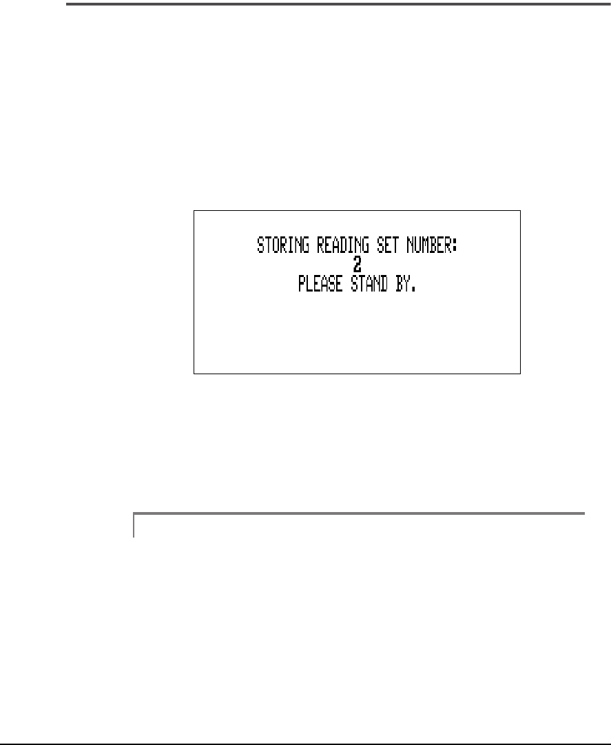
Storing Data Sets
From View Data the alignment readings and machine moves will be auto-
matically recorded and stored when the Enter key is pressed to exit from
either the dual tolerance plot or the Horizontal Log screen if viewing addi-
tional data details. This step returns you to the program’s Main menu.
When the readings and moves are recorded, a screen listing the number of
readings recorded for the current alignment job will appear for a few sec-
onds.
11
A maximum of 20 reading can be stored per alignment job. The current
alignment readings must be different from the previous set for the readings
to be recorded. If more than 20 readings are acquired a message is dis-
played giving you the option of either discard the last reading taken or
overwriting the 20th reading with the last reading.
Note
If you decide to overwrite the 20th reading with the last
reading, it cannot be retrieved.

5-41
Machine Moves
Machine Moves
After defining the job, checking the foot pre-check, collecting alignment
data, and viewing the analysis of the alignment data, you are ready to see
what machine moves are required. This section shows the screens and
information that are available.
While in the Machine Moves section, in addition to viewing the required
corrections, you can watch them being made in live mode (and view six dif-
ferent solutions in each plane – horizontal and vertical). Within the vertical
and horizontal logs, you can see how the present alignment condition com-
pares to the tolerances goal you are shooting for.
Use the Enter key to first view the Vertical Move, and then the Horizontal
Move. A bullseye on each of the move screens displays the corresponding
tolerances. The alignment readings and machine moves will be automati-
cally recorded when the Enter key is pressed to exit from the Horizontal
Move screen.
When the readings and moves are recorded, a screen listing the number of
readings recorded for the current alignment job (maximum of 20) will
appear for a few seconds. The number of readings recorded will also be dis-
played in the lower right of the Main menu screen.
Note
The alignment readings must be different from the previous set
for the current set of readings to be recorded.
5-42 Using UltraSpec Alignment - General Overview
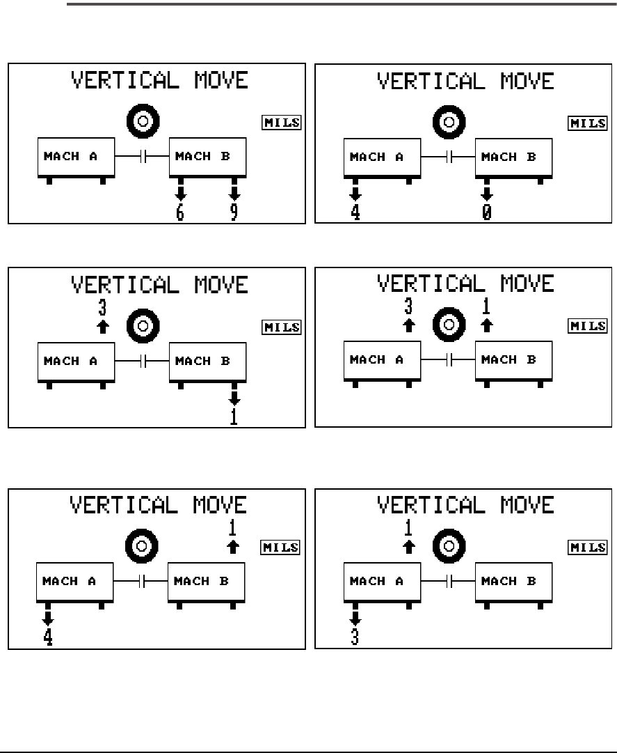
Vertical Move

5-43
Machine Moves
One of the six screens shown on the previous page (side view) will be dis-
played when entering the Machine Move section. Each screen shows a sep-
arate solution to bring the equipment into alignment. Solutions are
expressed in mils or millimeters and show the direction the equipment
should be moved.
To select the screens, press the Left/Right Arrow to toggle through them.
Except for first reading sets, all the screens default back to the solution
arrangement they were in when last used. For first reading sets, the left
machine will normally be selected. However, when Motor or Move are on
the right side, they will be selected.
The target indicates how close the machine horizontal or vertical positions
are to being in tolerance. The center (bullseye) indicates an excellent range.
The middle ring represents an acceptable range. The outer ring represents
> 1 times and < 2 times the acceptable range. No ring highlighted indicates
> 2 times acceptable range.
Press the Enter key to proceed to the Horizontal Move screen.
Note
Even though it isn’t indicated on the Vertical Machine Moves
screen, it is possible to perform a live move in the vertical
direction. Refer to “Using Live Mode” on page 5-45 for details.
5-44 Using UltraSpec Alignment - General Overview
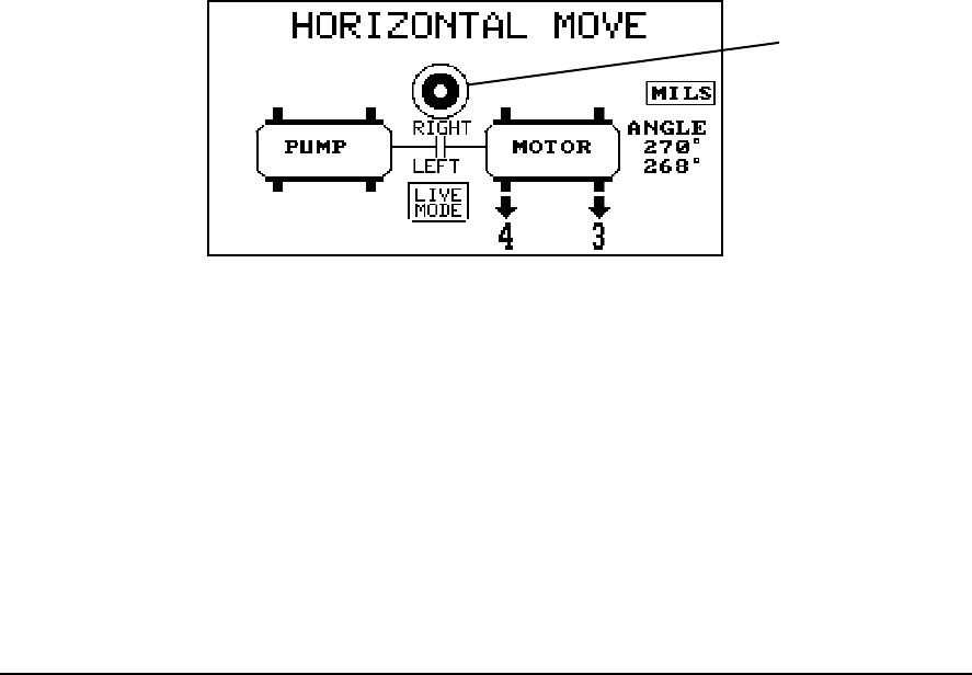
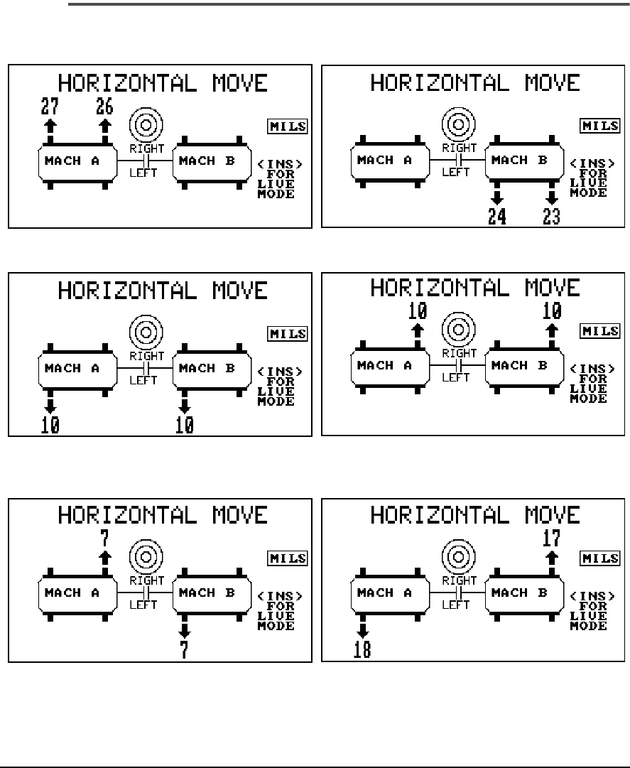
Horizontal Move
5-45
Machine Moves
One of the six screens shown on the previous page (top view) will be dis-
played when entering the Horizontal Move section. Just like the Vertical
move section, each screen shows a separate solution to bring the equipment
into alignment. Solutions are expressed in mils or millimeters and show the
direction the equipment should be moved.
The target indicates how close the machine horizontal or vertical positions
are to being in tolerance. The center (bullseye) indicates an excellent range.
The middle ring represents an acceptable range. The outer ring represents
> 1 times and < 2 times the acceptable range. No ring highlighted indicates
> 2 times acceptable range.
To select the screens, press the Left/Right Arrow to toggle through them.
Except for first reading sets, all the screens default back to the solution
arrangement they were in when last used. For first reading sets, the left
machine will normally be selected. However, when Motor or Move are on
the right side, they will be selected.
To exit Machines Moves and return to the Main menu, press the Enter key.
To enter Live Mode, see “Using Live Mode” below.
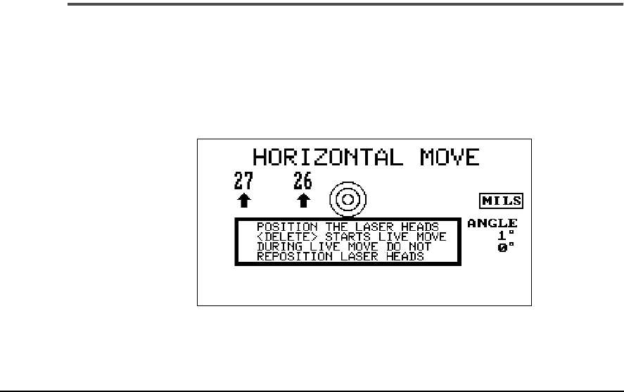
Using Live Mode
To activate the live mode in either the Vertical or Horizontal direction,
press the Insert key. The analyzer will prompt you to position the fixtures
to any rotational position.
Place the fixtures at any rotational position and press <Delete> to start.
12

5-46 Using UltraSpec Alignment - General Overview
Warning!
Do not change the rotational position after <Delete> is
pressed. This will cause the move to be incorrect.
Warning!
Do not loosen the machine feet hold down bolts until
after you have entered Live mode (after the Delete key
has been pressed). Loosening the hold down bolts prior
to entering Live mode can cause the move to be incor-
rect.
Note
The angular position information of the laser heads is shown to
the right of the machines.
5-47
Machine Moves
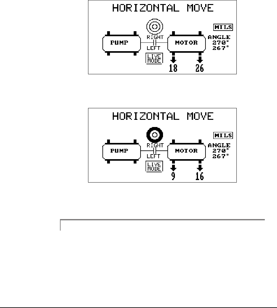
After the fixtures are in the chosen rotational position, press the Delete key
to start the live mode, and then move the machine(s) until they are within
tolerance.
Live Mode active with machine position more than
2 x out of acceptable tolerance
Live Mode active with machine position more than
1 x but less than 2 x out of acceptable tolerance
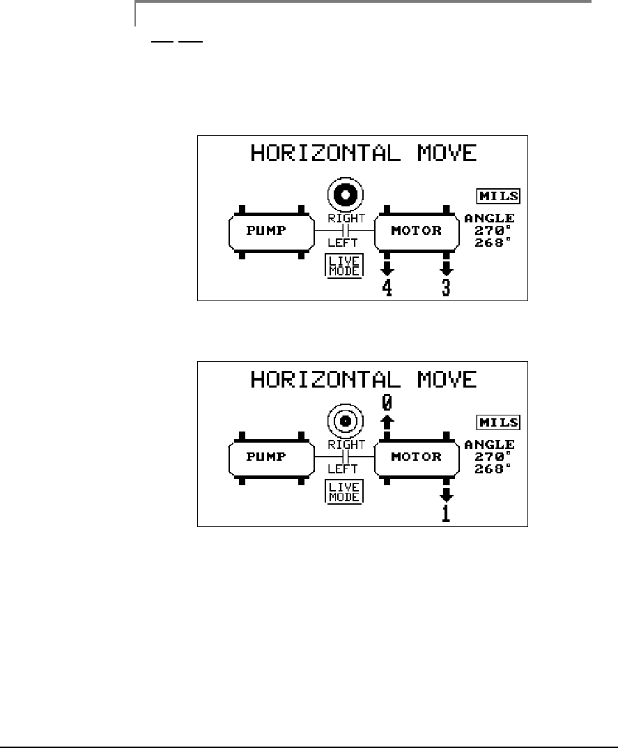
Warning!
When the machine(s) are within tolerance, before exiting
the Live mode, tighten the machine hold down bolts. If
readjustments to the machine(s) remain within tolerance
when the hold down bolts are tightened, then press the
Enter key to exit Live mode and return to the Machine
Moves screen.
5-48 Using UltraSpec Alignment - General Overview
Warning!
Do not use a hammer to move machines. These impacts
may move either sensor head, causing improper machine
positioning. CSI recommends that you use jack bolts
(permanent or portable).
Live Mode in acceptable range
Live Mode in excellent range
5-49
Machine Moves
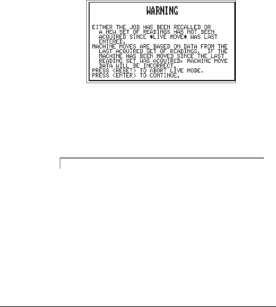
If a live move is done in the vertical direction, if you go directly to the Hor-
izontal Move screen (or visa versa) and press the Insert key to start the Live
Mode, the following message will be displayed.
13
Once a live move is done in either the vertical or horizontal direction, a
second live move should not be done in the opposite direction without first
acquiring a new set of laser readings.
If this situation occurs, press the Reset/Main key to abort the Live mode
and return to the Main menu or press Enter to continue with the Live
mode.
Note
This message is also displayed on a recalled alignment job if a
new set of data has not been acquired since the job was
recalled.

5-50 Using UltraSpec Alignment - General Overview

Chapter
6-1
6
Acquiring Alignment Data
Data Collection Methods - Overview
In this chapter, we will examine each of the modes which can be used for
acquiring alignment data for the purpose of shaft alignment. It is assumed
that you have previously read the chapter “Using UltraSpec Alignment -
General Overview” on page 5-1. Therefore, this chapter does not explain
the various functions such as Job Definition and Soft Foot analysis which are
common to all modes.
Note
Use of the Straightness mode is discussed in “Straightness
Application” on page 7-1.
4 Point Methods - General Information
There are two fundamental methods by which the data is acquired for shaft
alignment calculations, the 4 point modes and the sweep modes. The 4
point modes require data to be taken at positions perpendicular and par-
allel to the axis in which the machine’s position can be adjusted horizon-
tally. This is sometimes called the clock method and most often uses data
readings at 12 o’clock (0 or 360°), at 3 o’clock (90°), at 6 o’clock (180°), and
at 9 o’clock (270°). This is typical of the data acquired by those trained in
using a scaled graph to manually arrive at an alignment solution using the
reverse dial indicator method.
42

6-2 Acquiring Alignment Data
When using the 4 point methods, ideally, the sum of the two horizontal
measurements will equal the sum of the two vertical measurements. This
relationship may be used to check the data for validity. Any variance
greater than 10-20% is a cause for concern. When this occurs, repeat the
readings to verify that a variation wasn’t accidentally introduced by the
user. For example, by using the fixtures as levers to turn the shaft or by not
controlling the torsional play in the coupling. Damaged regions in rolling
element bearings and shaft rubs could also cause problems, but are less
common.
Because of this same mathematical relationship, having any 3 of the 4
points would allow the fourth point to be calculated. This can be useful
when obstructions only allow you to rotate the laser fixtures to three of the
four clock positions. Unfortunately, estimating the fourth point like this
removes the ability to check the validity of the data. Abnormal readings at
any one of the three known points could cause error. Therefore, use this
technique with caution and only when absolutely necessary. CSI recom-
mends using a partial sweep method rather than the three 90° clock points
if the arc of rotation is restricted.
Sweep Methods - General Information
The sweep modes use data acquired at several different angular positions.
By using CSI’s patented process, this data is translated into readings for the
four clock positions. There are several advantages to the sweep method
over the 4 point method of acquiring data. Data does not have to be
acquired at 3 or 4 specific angular locations; any angular positions will
work. More data points are used to arrive at the true rotational behavior of
the shaft, therefore a discrepancy in one area of the rotation does not have
as great an effect. If a full rotation of the shaft is not possible, the three point
method still requires at least 180° of shaft rotation, which must begin at one
of the four designated positions; the sweep method can use rotations less
than 90° starting from any position. However, keep in mind that no matter
what method is used, reconstructing a complete picture using partial data is
never as desirable as starting with a complete picture.

6-3
When using the sweep mode calculations are completed in the following
manner. If readings were taken from each laser target at 1° intervals (with
the position as the Y- axis and the rotational position as the X-axis), a sine
wave would be formed. Even when only part of the sine wave is completed,
UltraSpec Alignment software can complete the remainder of the curve.
Called curve fitting, all values used to determine the machine moves can be
obtained from the completed sine waves.
CSI recommends you sweep at least 90°, however accuracy may be
reduced even at 90°. At the very least, this could result in more machine
moves being required to achieve satisfactory alignment. Each head will
store up to 180 readings (the higher the number, the greater the accuracy),
however, all 180 readings are not required to determine the sine wave. You
must have at least three readings and they should be spaced at large inter-
vals in the shaft rotation.
After the sweep data has been transferred from the heads to the analyzer,
the data will be automatically curve fit. The quality of the data is shown by
the curve fit percentage. If more points are located off the sine wave (the
greater distance from the curve), the lower the percentage will be. A high
number of points on the curve means that most of the data were acquired
from points that lay on the sine curve.
Bearing faults, rubs, and looseness are all problems which can cause points
not to fall on the curve. These mechanical problems can cause all data to
have some low levels of variability. This variability may appear as random-
ness, or “noise”. This noise is not generally of much concern when the level
of misalignment is high, however, as the amplitudes measured from mis-
alignment decrease,
the ratio of noise to the signal increases and the percentages of
fit may worsen
. Although the program will automatically condition the data
for an improved fit in such a circumstance, there may be times when the
user chooses to change methods or to manually condition the data using the
View Data function (see Sine Fit under “Additional Data Detail” on page
5-34).

6-4 Acquiring Alignment Data
Quick Spec
This option is set in the Alignment Setup menu and is accessed by using the
Options key. When set to Yes, Quick Spec works with any selected shaft
alignment method to give an abbreviated means of checking whether the
machine alignment is in tolerance. If the machine alignment is unaccept-
able, you can provide additional machine dimensions and continue as a
normal alignment.
Note
Refer to “Quick Spec” on page 6-33 for additional information
about using Quick Spec.

6-5
Auto Sweep
Since they have built-in inclinometers, CSI’s laser fixtures allow data to be
automatically acquired while the shaft is rotated. The arc of rotation can
vary from as little as 45° to a full 360° (one revolution). This mode is espe-
cially useful when the 4 point measurement technique is impractical or
when inconsistencies in shaft position exist at points in the rotation. With
the Auto Sweep method, data readings or values are automatically acquired
and stored in the laser heads every 2 degrees; therefore, in a 360° sweep it
is possible to acquire up to 180 data readings per laser head.
Note
Although it is possible to acquire up to 180 data readings, not
all of the data readings are used to calculate the machine’s
alignment condition. Refer to “Additional Data Detail” on page
5-34.
To acquire data using the Auto Sweep method, you must first select Auto
Sweep as the method from the Alignment Setup menu (accessed by
pressing the Options Key). Once this method is shown, using the Up/down
Arrow keys to select and the number keys on the keypad to toggle the selec-
tion, set the Acquisition (ACQ) Mode to either Standard or Averaging.

6-6 Acquiring Alignment Data
Standard
- this mode of operation (sometimes referred to as the Unidirec-
tional Mode) is the mode that is most often used during Auto Sweep align-
ments. In this mode, a direction of rotation is automatically defined for data
acquisition based on the first rotation to progress past the starting point by
20 degrees. In the Standard Mode, data acquired in the Data Acquisition
Direction of Rotation will always overwrite any previous data stored at the
same angular position. This includes data acquired at its defined angle posi-
tion. In this mode of operation, once the direction of rotation is defined by
the laser heads, only the data in that direction of rotation will be acquired;
therefore, any backward rotation of the shaft due to backlash will not be
acquired and thus will not affect the alignment results. The following sce-
nario illustrates this more clearly.
1. ··· When the analyzer initializes the laser heads, all data is cleared and
their current position is defined as the Starting Point for
determination of the data collection direction.
2.··· If the laser heads are rotated less than 20 degrees in the counter-
clockwise position from the defined starting point, data is collected
for this rotation but it is not committed and permanently stored.
3.··· If the counter-clockwise rotation is stopped before the 20 degrees and
laser heads are now rotated in the clockwise direction, data will be
ignored (not acquired) until the Starting Point is reached again. At this
point all data collected in the counter-clockwise direction is cleared
and the data acquisition is started in the clockwise direction.
4.··· This mode of operation will continue as long as the laser heads are
rotated in both the clockwise and counter-clockwise directions until a
rotation of more than 20 degrees occurs in on of the directions of
rotation. Once the 20 degrees point is passed, all acquired data is
committed and stored and the direction of rotation is defined as the
Data Acquisition Direction of Rotation.
5.··· Now data will only be acquired when the laser heads are rotated in
the same direction as the defined Data Acquisition Direction of
Rotation.

6-7
Averaging
- this mode of operation is intended to allow multiple sampling
of data in order to reduce the noise in the data by averaging all of the
acquired values. In the Average Mode, a Data Acquisition Directions of
rotation is defined in the same manner as it is in the Standard Mode. How-
ever, instead of always over-writing the last data reading stored at the same
angular position, is will be averaged with previous readings if the laser head
has been moved at least 20 degrees in the reverse direction or a full 360
degree sweep is performed. In this mode of operation, once the direction
of rotation is defined by the laser heads, only the data in that direction of
rotation will be acquired; therefore, any backward rotation of the shaft due
to backlash will not be acquired and thus will not affect the alignment
results. The following scenario will clarify the intended operation.
1.····Assume that the Data Acquisition Direction of rotation is defined as
clockwise (see scenario for Standard Mode).
2. ···If the laser heads are rotated in the clockwise direction to an angle of
50 degrees, data is acquired and stored for each angular position in
this rotation.
3. ···If the laser heads are then rotated in the counter-clockwise direction
for 10 degrees (back to an angle of 40 degrees), all data acquired is
ignored in the counter-clockwise direction since the direction of
rotation is not in the Data Acquisition Direction of rotation.
4. ···If the laser heads are again rotated in the clockwise direction for 25
degrees (to an angle of 65 degrees), the data acquired for each angular
position will over-write the previous data acquired because the angle
of negative rotation was not at least 20 degrees.
5. ···If the laser heads are then rotated in the counter-clockwise direction
for 30 degrees (back to an angle of 35 degrees), all data is ignored
because of the direction of rotation.
6. ···Now if the laser heads are rotated in the clockwise direction for 360
degrees. The data for the angular positions in the range 36 - 65
degrees will be averaged with the previous values since there has
been a rotation of at least 20 degrees away from the stopping point.
The data for the angular positions in the range 66 - 359 degrees will
receive a data value since the direction of rotation is correct. The data
angular positions in the range 0 - 35 degrees will be averaged with the
previous values since the rotation in the clockwise direction passed
the starting point (i.e. 360 degree sweep).
6-8 Acquiring Alignment Data
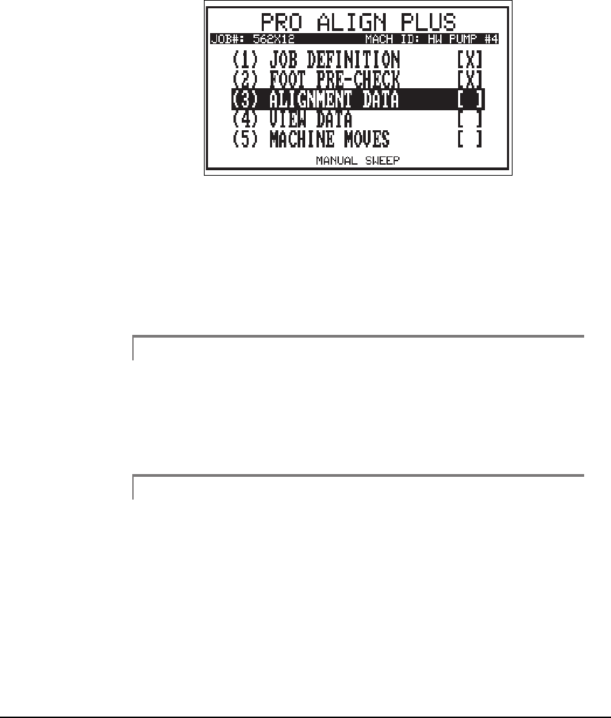
The current alignment method is always shown at the bottom center of the
main menu. Once the job has been defined and any soft foot has been cor-
rected (if necessary), prepare to measure the misalignment by selecting
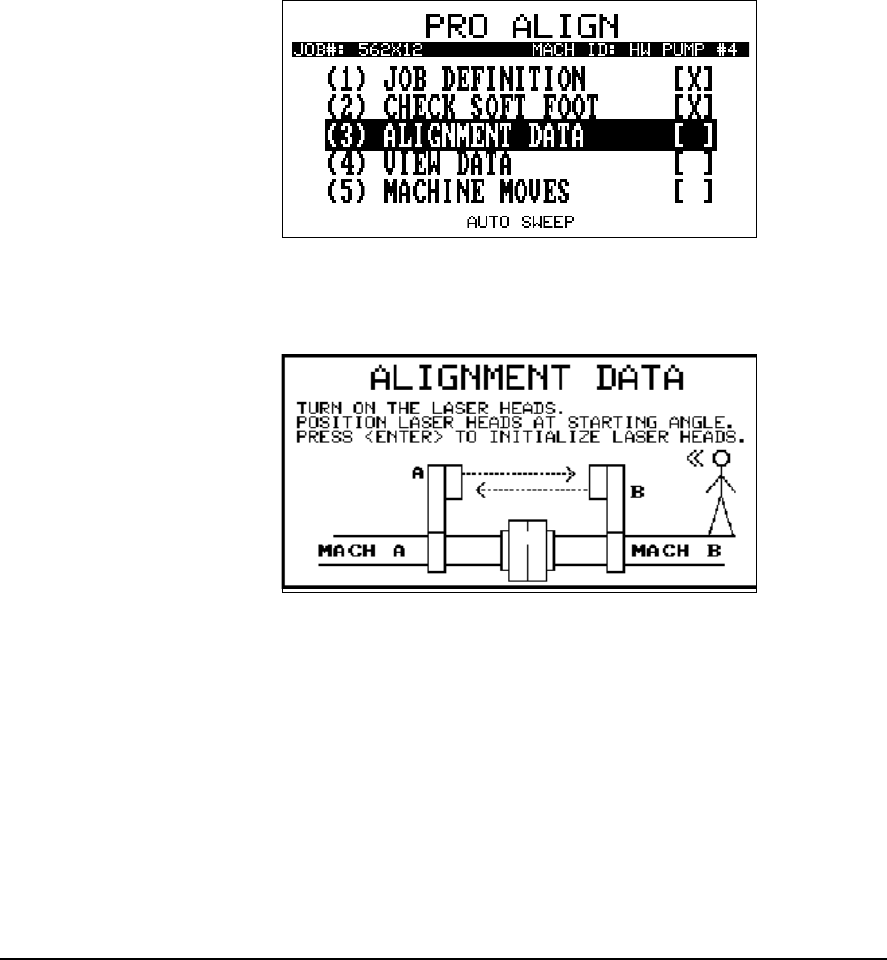
Alignment Data from the Main Menu.
1
With Alignment Data highlighted, press the Enter key to start the data
acquisition procedure. The following screen will be displayed.
2
The next screen directs you to turn on the laser heads, position them at any
angular position you desire to start from, and then press the enter key to
initialize the laser heads. It is not required to define a sweep arc range and
direction of rotation due to the increased number of data readings acquired
every 2 degrees and the process, which automatically defines the direction
of rotation. Once the laser heads are initialized, the next screen appears
prompting you to now acquire the data by rotating the laser heads. After
the laser heads have been rotated, press the Enter key transmit or transfer
the data from the laser heads to the analyzer.
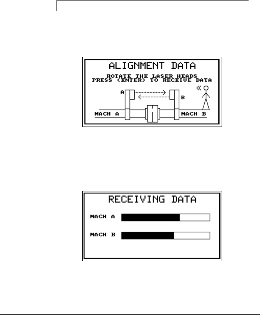
6-9
Note
For the greatest accuracy and repeatability, all readings should
be acquired using the same direction of rotation. In addition, it
is best to use the same direction of rotation as the machine nor-
mally operates.
3
The 8215/8225 laser fixtures are designed to be rotated a full revolution in
two seconds. As with any sweep, a smooth, uniform acceleration and decel-
eration during the rotation of the laser heads is necessary for accurate, reli-
able, and repeatable data. during the transfer, the “Receiving Data” screen
will be displayed showing the progress of the data transfer for each laser
head.
4
6-10 Acquiring Alignment Data
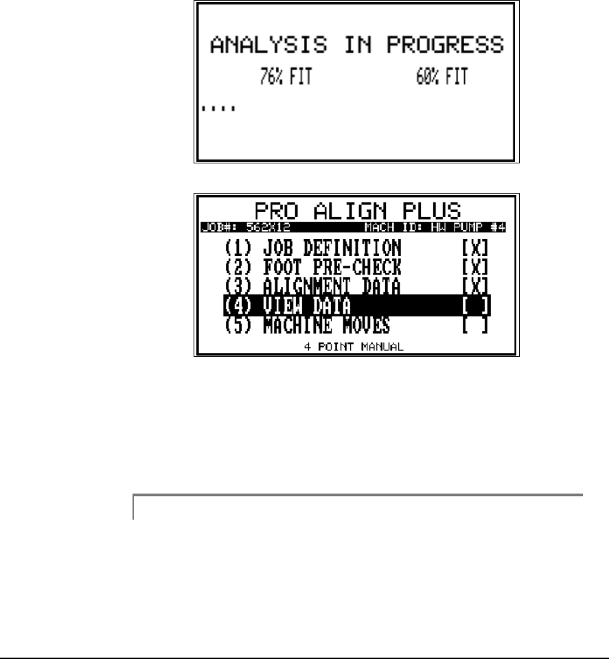
When the data transfer is complete, an Analysis in Progress screen similar
to the following is displayed while the data is curved to fit a sine wave. If
the fit is satisfactory (85% and above), you are returned to the main menu
where the data may now be viewed.
5
6
Otherwise, you are warned that the data is “Unfit” (less than 85%). At this
point you should either repeat the data acquisition or try to manually con-
dition or edit the data. This built-in check helps alert you to the data losing
reliability in the misalignment calculations. Refer to “Additional Data
Detail” on page 5-34 for more information.
Note
Remember, when shaft movement due to other than misalign-
ment is present in the data this will appear as a randomness
(noise) in the data. This is not normally a problem when the
misalignment is great, but will increasingly interfere as the mis-
alignment decreases. therefore, the better the alignment, the
more likely the chance of seeing the Unfit data warning.

6-11
If you do encounter a machine where this becomes a problem too great to
overcome, consider switching to an alternative method such as Manual
Sweep or 4 Point Auto.
6-12 Acquiring Alignment Data
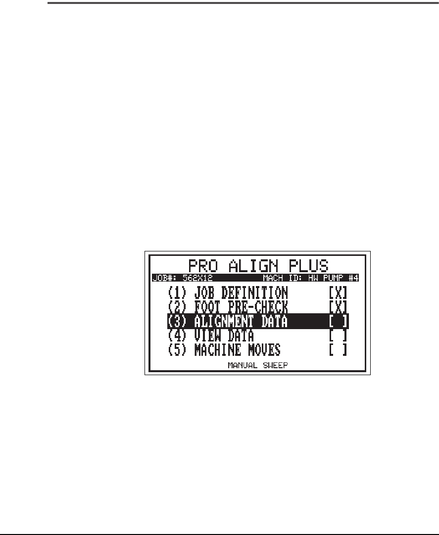
Manual Sweep
Manual Sweep functions similarly to the Auto Sweep mode except that the
laser heads, or shafts, are stopped at each position where data is to be taken
and a key pressed to store a reading. Data from up to 36 positions may be
recorded. This mode is especially useful for performing uncoupled or non-
rotational alignments. This is the recommended sweep method for sweeps
that are <75º.
The current alignment method is always shown at the bottom center of the
screen. The alignment method is selected from the Alignment Setup menu
which is accessed using the Options key. Once the Manual Sweep method
is shown, using the Up/Down Arrow keys to select and the number keys
on the keypad to toggle the selection, set the sample rate.
Sample Rate –
determines the number of data samples that are to be col-
lected and averaged together to produce a single Laser PSD reading. Use
the Left and Right Arrow keys to toggle sample rate from 1 to 25 samples.
The default is 2.
Manual Sweep Measurement Method
6-13
After the job has been defined and any soft foot condition corrected (if nec-
essary), select Alignment Data to acquire a new set of shaft readings.
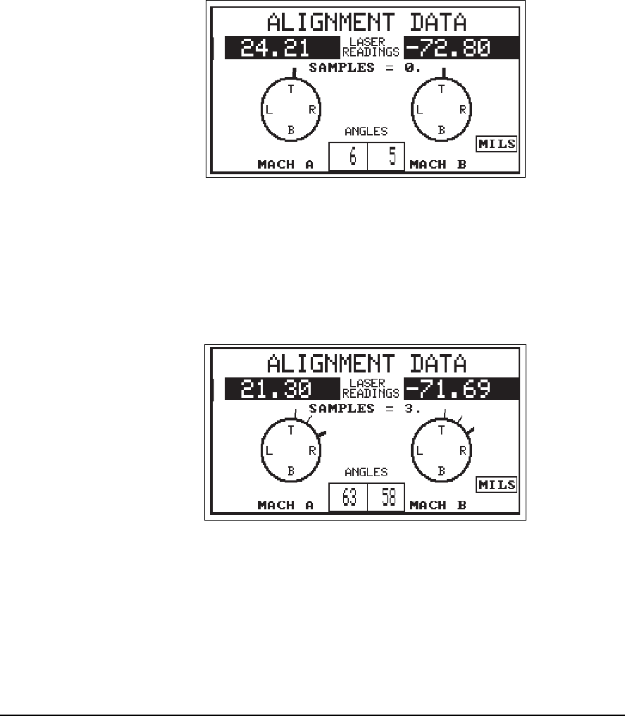
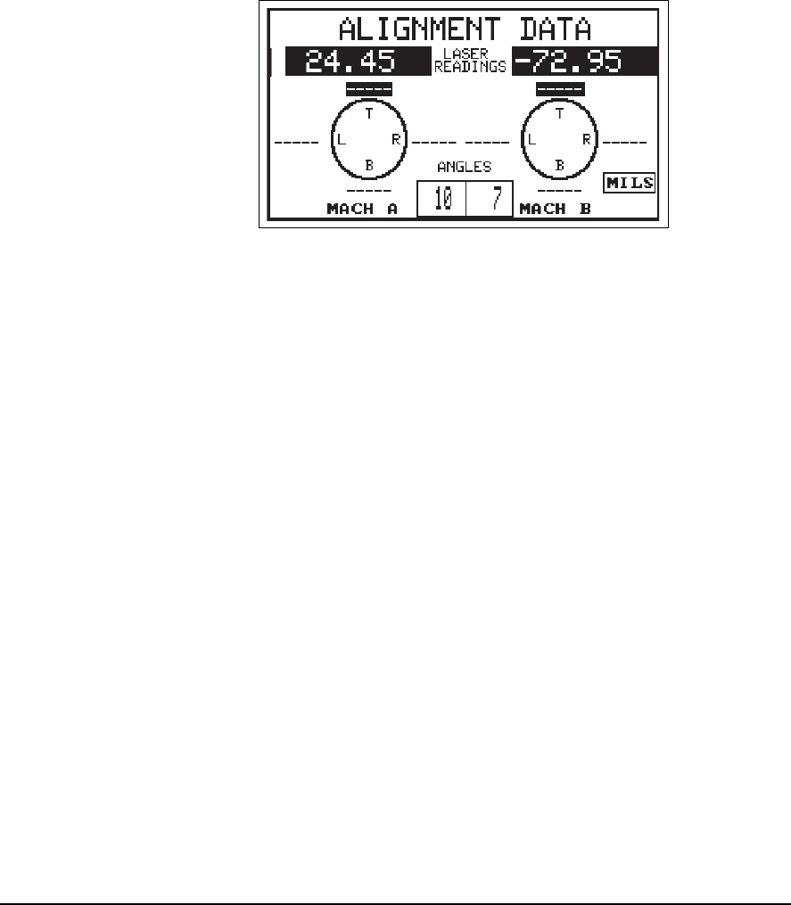
7
The current laser readings are shown in reverse video just below the screen
title line. The current laser head position is shown graphically by a heavy
black line on the circles and numerically by the degree readings at the
bottom of the screen.
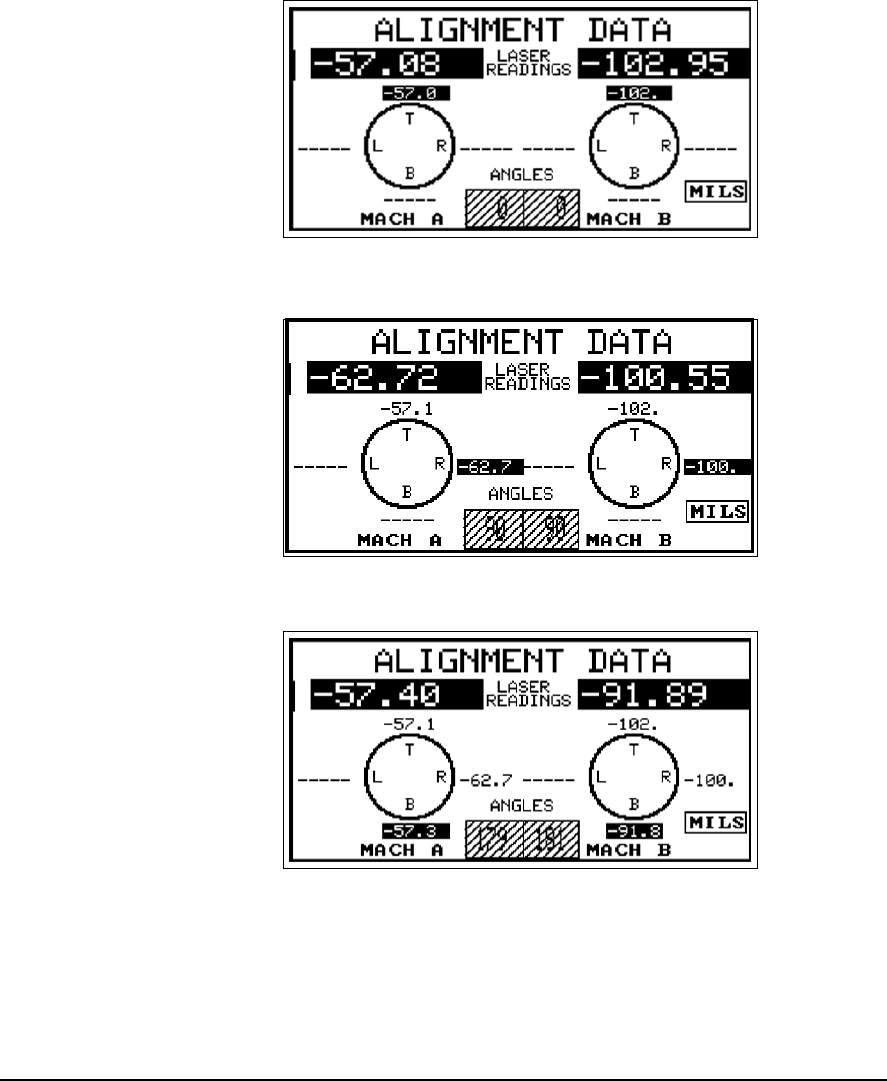
When the head positions and data are as desired press any number key on
the keypad to record data at the given point. The number of samples,
shown at the center of the screen, will increment by one (36 max).
8
Each time a data point is recorded and the heads are rotated to a new posi-
tion, a thinner line is left behind to denote where data was acquired.
6-14 Acquiring Alignment Data
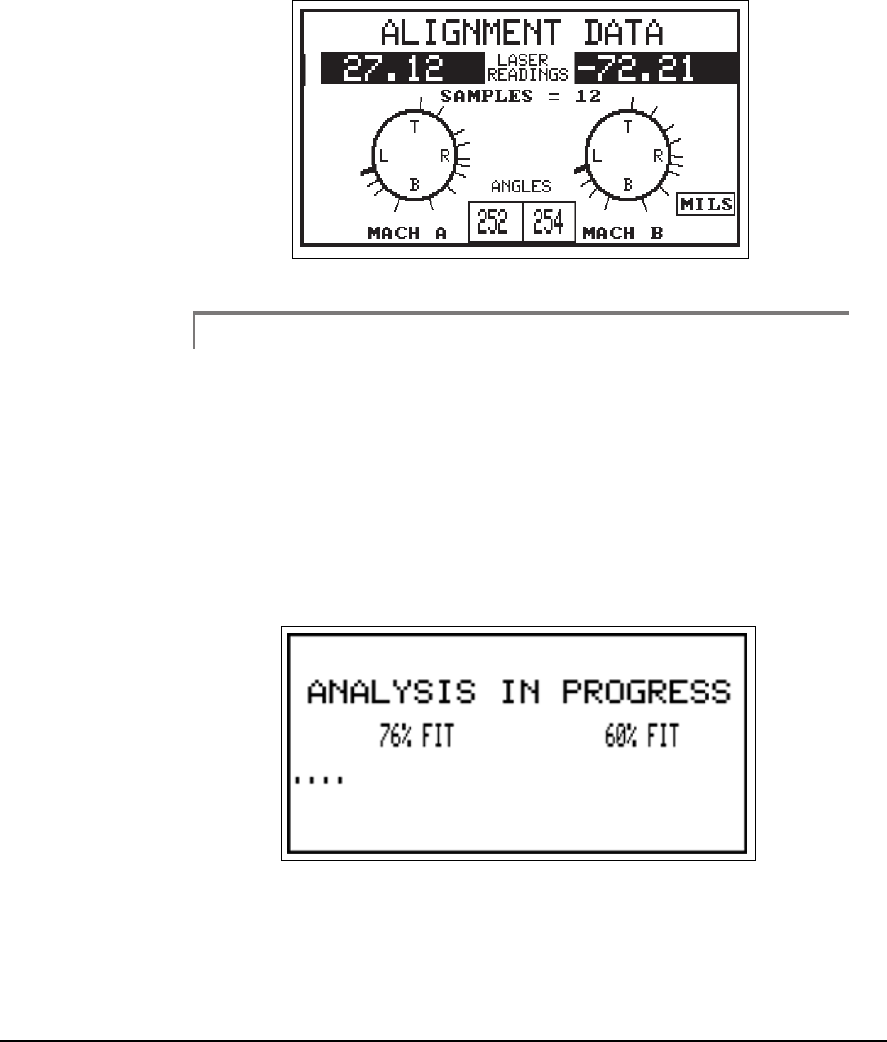
. 9
Note
A minimum of three data points over a 45º sweep arc is
required, but CSI recommends a minimum of 8 data points
(samples) acquired over a sweep arc of at least 90º.
When all the desired samples (36 max.) have been acquired, press the Enter
key to accept the data. An “Analysis In Progress” screen similar to the fol-
lowing is displayed while the data is curve fit to a sine wave. If the fit is sat-
isfactory (85% and above), you are returned to the main menu where the
data may now be viewed.
10
6-15
Otherwise, you are warned the data is “Unfit” (less than 85%). At this point
you should either repeat the data acquisition or try to manually condition
or edit the data. This built-in check helps alert you to the data losing reli-
ability in the misalignment calculations. Refer to “Additional Data Detail”
on page 5-34 for more information.
Note
For the greatest accuracy and repeatability, all readings should
be acquired using the same direction of rotation. In addition, it
is best to use the same direction of rotation as the machine nor-
mally operates.
Note
Remember, when shaft movement due to causes other than
misalignment is present in the data this will appear as a ran-
domness (noise) in the data. This is not normally a problem
when the misalignment great, but will increasingly interfere as
the misalignment decreases. Therefore, the better the align-
ment the more likely the chance of seeing the Unfit data
warning.
6-16 Acquiring Alignment Data
If you do encounter a machine where this becomes a problem too great to
overcome, consider switching to an alternative method such as 4 Point
Auto.
4 Point Auto
The 4 Point Auto method is a more traditional style of acquiring data for
alignment. The laser heads are mounted on a shaft, and the shaft is then
rotated so that data can be taken when the laser heads are at the 12 o’clock
(0 or 360°), 3 o’clock (90°), 6 o’clock (180°), and 9 o’clock (270°) positions.
The readings are continuously averaged whenever the laser heads are at
one of these positions and automatically recorded when the shaft is rotated
to the next position. The averaging process reduces variation from jitter due
to background vibration or from slight changes in the angular position of
the heads.
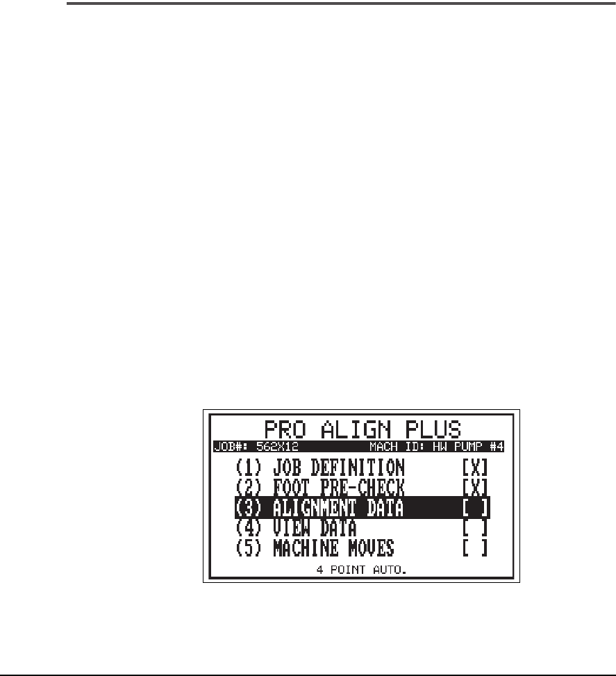
The current alignment method is always shown at the bottom center of the
screen. The alignment method is selected from the Alignment Setup menu
which is accessed using the Options key. Once the 4-point method is
shown, set the sample rate. Use the Up and Down Arrow Keys to select the
sample rate and the Number keys on the keypad to toggle the selection.
Sample Rate –
determines the number of data samples that are to be col-
lected and averaged together to produce a single Laser PSD reading. Use
the Left and Right Arrow keys to toggle sample rate from 1 to 25 samples.
The default is 2.
6-17
After the job has been defined and any soft foot condition corrected (if nec-
essary), select Alignment Data to acquire a new set of shaft readings.
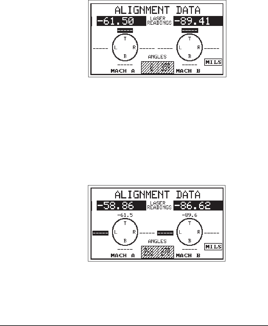
The current laser readings are shown in reverse video just below the title
line of the data acquisition screen. When the laser heads are at one of the
desired clock positions, the angle readouts at the bottom center of the
screen get cross hatches over the numbers, you will hear the analyzer beep
(and the red LED on the front panel of the analyzer will illuminate) each
time a new reading is measured. The heads must be within one degree of
the desired position (average of both angles). In Auto mode the data is auto-
matically placed in the correct clock position and it is averaged continu-
ously until you move out of the desired clock position. You can clear and
restart the averager at any time by pressing the Alt/Delete key while read-
ings are being acquired. The data at the four clock positions is the averaged
value. The position currently highlighted is the one for which data is being
acquired.
If the laser heads can only be rotated to three of the positions, then press
Enter after the third set of data has been collected, and the fourth is auto-
matically calculated. Using only three readings increases the likelihood of
error and does not allow the instrument to check data validity. CSI does not
recommend using only three readings if four are available.
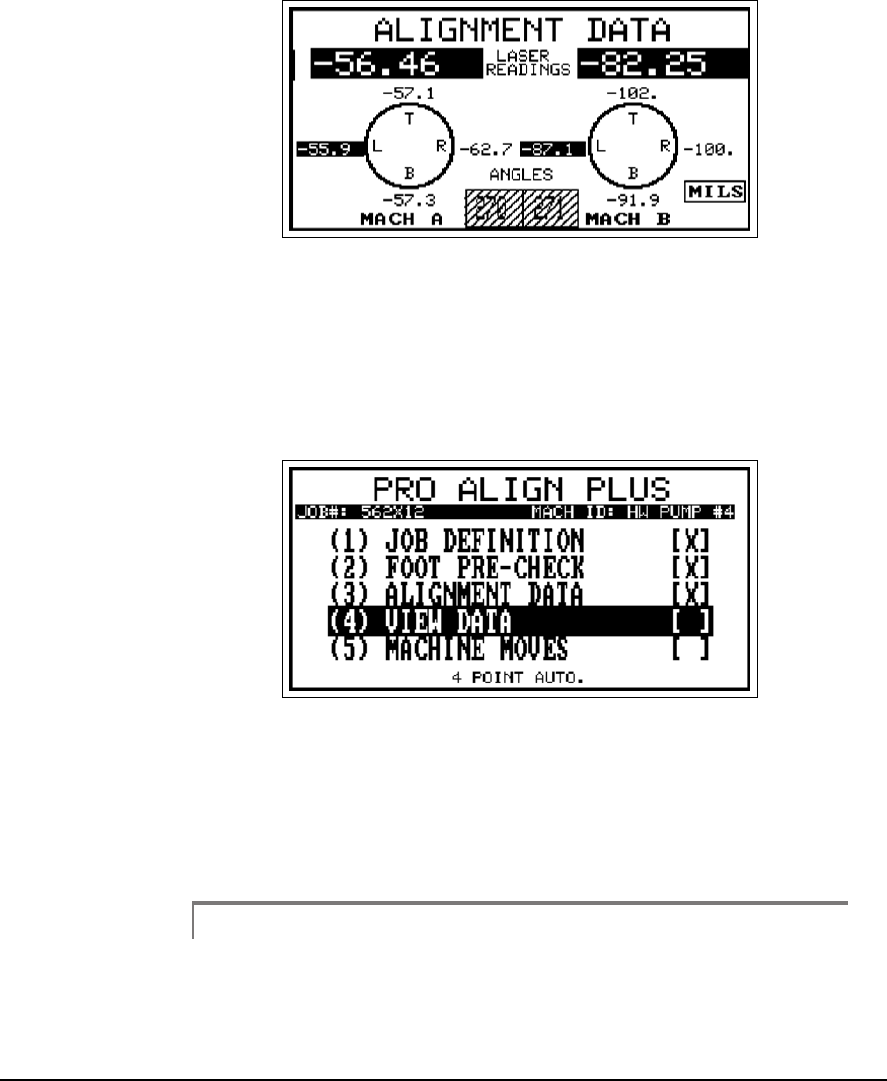
11
6-18 Acquiring Alignment Data
Data Acquired at 12 O’clock (270°)
Data Acquired at 3 O’clock (0°)
Data Acquired at 6 O’clock (90°)
6-19
Data Acquired at 9 O’clock (90°)
When all the data has been acquired all the desired points, press the Enter
key to accept the data. At this point the data is checked for validity (refer to
“Data Quality” on page 5-27 for more information). If the data validity is
satisfactory, you are returned to the main menu where the data may now
be viewed.
Otherwise, you are warned that a data validity error exists. At this point you
should either repeat the data acquisition to check for accuracy. This built-
in check helps alert you to the data losing reliability in the misalignment
calculations.
Note
For the greatest accuracy and repeatability, all readings should
be acquired using the same direction of rotation. In addition, it
is best to use the same direction of rotation as the machine nor-
mally operates.

6-20 Acquiring Alignment Data
Note
Remember, when shaft movement due to causes other than
misalignment is present in the data this will appear as a ran-
domness (noise) in the data. This is not normally a problem
when the misalignment great, but will increasingly interfere as
the misalignment decreases. Therefore, the better the align-
ment the more likely the chance of seeing the data validity
warning.

6-21
4 Point Manual
The 4 Point Manual method is similar to the 4 Point Auto mode except that
the user has complete control over when data is acquired and which of the
four measurement positions it will be used in. This mode is useful when the
machinery is not mounted in a true horizontal orientation, so that the incli-
nometer is not effective, or when the clock positions relative to vertical and
horizontal base movements of the machine are nonstandard.
The current alignment method is always shown at the bottom center of the
screen. The alignment method is selected from the Alignment Setup menu
which is accessed using the Options key. Once the 4 point method is
shown, using the Up/Down Arrow keys to select and the Number keys on
the keypad to toggle the selection, set the Sample Rate.
Sample Rate –
determines the number of data samples that are to be col-
lected and averaged together to produce a single Laser PSD reading. Use
the Left and Right Arrow keys to toggle sample rate from 1 to 25 samples.
The default is 2.
After the job has been defined and any soft foot condition corrected (if nec-
essary), select Alignment Data to acquire a set of shaft readings.
6-22 Acquiring Alignment Data
The current laser head readings are shown in reverse video just below the
title line of the display. The current head angle is shown at the bottom
center of the screen. To acquire data, use the arrow keys to move the
reverse video of the data point to be acquired to the desired position. When
using this mode the user must be very careful to get the desired readings
into the desired positions. That is why this is called the 4 Point Manual
method. All readings should be 90° from each other, but this does allow the
program to handle special circumstances where the shaft of the machine is
not in the horizontal plane. There is no averaging of the displayed data and
no safeguards against data being placed in the wrong position.
12
When the desired data position is highlighted and the data is acceptable,
press any number key to insert the data into the selected position.
After 3 or 4 positions have had data inserted, pressing the Enter key will
complete acquisition and accept the data.
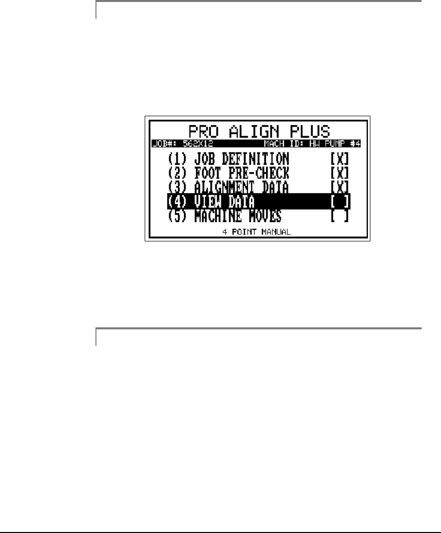
6-23
Note
CSI does not recommend using only three readings if four are
available.
At this point the data is checked for validity (refer to “Data Quality” on
page 5-27 for more information). If the data validity is satisfactory, you are
returned to the main menu where the data may now be viewed.
13
Otherwise, you are warned that a data validity error exists. At this point you
should either repeat the data acquisition to check for accuracy. This built-
in check helps alert you to the data losing reliability in the misalignment
calculations.
Note
For the greatest accuracy and repeatability, all readings should
be acquired using the same direction of rotation. In addition, it
is best to use the same direction of rotation as the machine nor-
mally operates.

6-24 Acquiring Alignment Data
Note
Remember, when shaft movement due to causes other than
misalignment is present in the data this will appear as a ran-
domness (noise) in the data. This is not normally a problem
when the misalignment great, but will increasingly interfere as
the misalignment decreases. Therefore, the better the align-
ment the more likely the chance of seeing the data validity
warning.
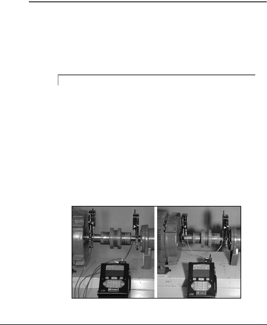
6-25
Dual Pass
Dual Pass functions similar to the Auto Sweep mode except data is automat-
ically acquired as each laser head passes by each other. This mode, like
Manual Sweep, is useful for performing uncoupled or non-rotational align-
ments. In this mode of operation, PSD and angle data are only taken when
the laser beam of each laser head enters the “valid data” window centered
on the vertical centerline of the other head’s PSD.
Note
With the Dual Pass method, a special cable is required to syn-
chronize the two Laser Heads since they will be moved inde-
pendently of each other and will not always be in alignment
with each other. When using direct connect communication,
the Model 821510 direct connect cable is connected between
the laser heads and analyzer to synchronize the laser heads
while using the Dual Pass method. When using RF communi-
cation, the Model 8215C2-PM “Dual Pass” cable is connected
between the two laser heads to synchronize the laser heads
while using the Dual Pass method. For longer spans the Model
800002 and Model 800003 extension cables can be added
between the Model 821510 direct connect cable/Model
8215C2-PM “Dual Pass” cable and the laser heads.
Two ways of hooking up the laser heads for Dual Pass. Direct Connect (left) and RF
Communication (right).

6-26 Acquiring Alignment Data
To acquire data using the Dual Pass method, you must first select Dual Pass
as the method from the Alignment Setup menu (accessed by pressing the
Options key). Once this method is shown, using the Up/Down Arrow keys
to select and the number keys on the keypad to toggle the selection, set the
Target Window percentage.
• Target Window - determines the size of the valid data window
around the vertical centerline of the other laser head's PSD. Use any
number keys on the keypad to toggle the Target Window between
10%, 25%, 50%, 75%, and 100%. The default is 100%.
Note
If a lower percentage (smaller valid window) is selected, a
slower rotational sweep speed may be required especially with
a smaller PSD (e.g. with the 10mm x10mm PSD on the 8215).

6-27
The following scenario will more clearly illustrate how the Dual Pass
method operates.
1. ···When the analyzer initializes the laser heads, all data is cleared and
they enter the “Dual Pass” mode of operation.
2. ··The laser heads then begin detecting the presence of the other laser
head’s laser beam on its PSD. If a laser beam is not on a PSD, the
laser head's LED will be flashed solid yellow.
3. ··When the other laser head’s laser beam is detected on its PSD, the
laser beam is tracked as it crosses the PSD. As soon as the laser beam
is detected on the PSD, the laser head's LED will be or continue to
be (depending on the state it originally started from) flashed solid
yellow.
4. ··When a laser beam enters the “valid data” window around its PSD’s
vertical centerline, data is acquired. As valid data is acquired, the
laser head will flash its LED green once.
5. ··Data continues to be acquired while a laser beam is within the “valid
data” window. The position data that is closest to the vertical
centerline (i.e. horizontal position closes to zero) is the value that is
retained along with its angular position. As each data sample is taken
the LED on the Laser Head will flash green to indicate that a valid
data point has been acquired.
6. ··If a laser beam passes across the PSD so quickly that a data point is
not acquired within the “valid data” window, no data will be
acquired.
7. ···When a laser beam leaves the PSD completely, the acquired data
point is committed and stored.
8. ··The laser heads again begin detecting the presence of the other laser
head’s laser beam on its PSD and their LED's resumes to be flashed
solid yellow.
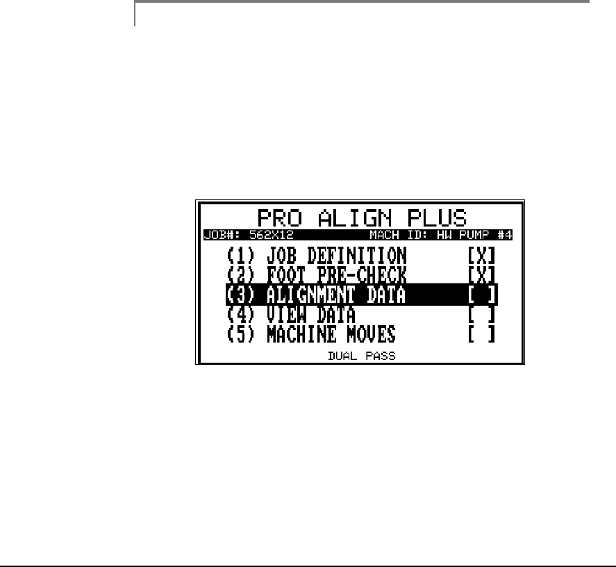
6-28 Acquiring Alignment Data
The typical method of operation will be for the user to initialize the laser
heads with the analyzer. One of the heads will then be moved to a new posi-
tion. Then the second head will be moved past the first head to a new posi-
tion. As the laser heads pass each other, the data will be acquired. The first
head will then be moved past the second head to a new position. Again, as
the laser heads pass each other, both laser heads will acquire the data. This
method continues until the user has acquired the necessary number of
passes and downloads the data to the analyzer. This may include several full
rotations of the laser heads.
Note
A minimum of three data points over a 45º sweep arc is
required, but CSI recommends a minimum of 8 data points
acquired over a sweep arc of at least 90º.
The current alignment method is always shown at the bottom center of the
main menu. Once the job has been defined and any soft foot has been cor-
rected (if necessary), prepare to measure the misalignment by selecting
Alignment Data from the Main Menu.
14
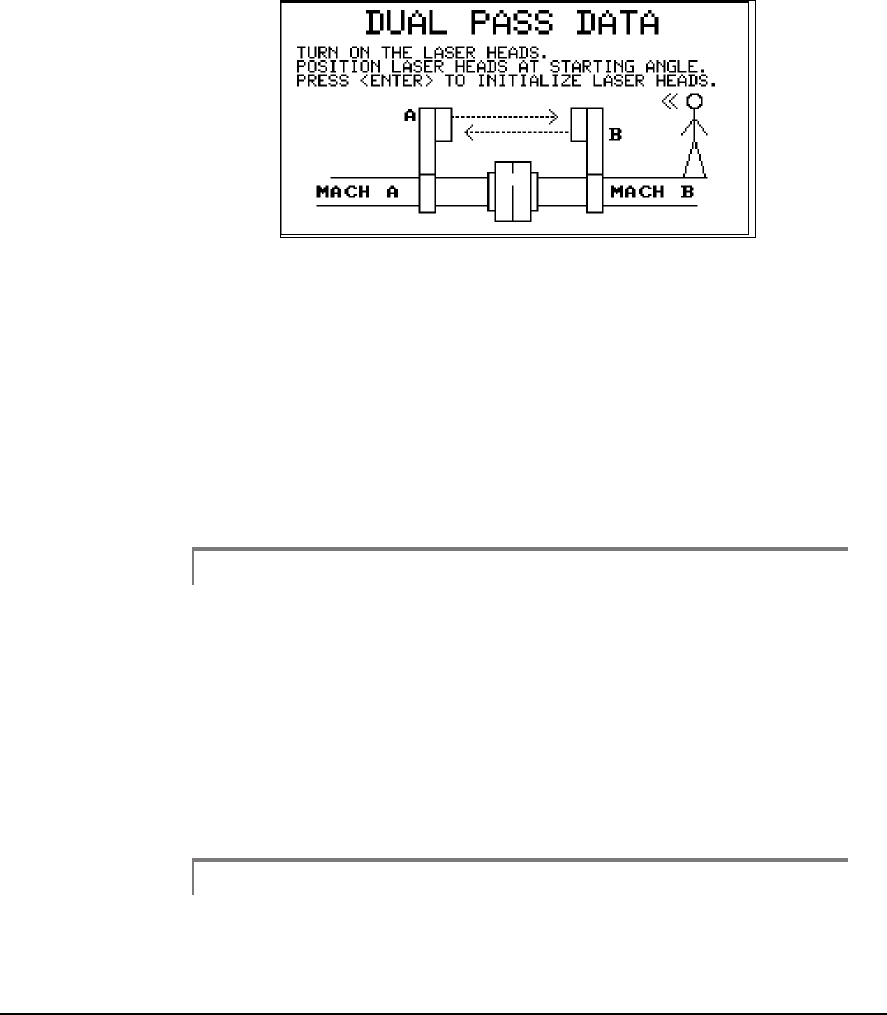
6-29
With Alignment Data highlighted, press the Enter key to start the data
acquisition procedure. The following screen will be displayed.
15
The next screen directs you to turn on the laser heads, position them at any
angular position you desire to start from, and then press the Enter key to
initialize the laser heads. It is not required to define a sweep arc range and
direction of rotation with the Dual Pass mode since this is a type of Manual
Sweep mode of operation. Once the laser heads are initialized the next
screen appears prompting you to now acquire the data by rotating the laser
heads. After the laser heads have been rotated as described in the above
scenario, press the Enter key transmit or transfer the data from the laser
heads to the analyzer.
Note
For the Auto Sweep and Dual Pass methods, if the laser heads
have not been turned off since they last acquired and stored a
set of data readings and prior to initializing them, pressing the
Alt/0 (Alt/Space) key will “Resend” the last set of data they
acquired and stored to the analyzer without having to resweep
the laser heads. This is useful if for some reason the data
transfer from the heads to the analyzer was aborted before it
was complete.
Caution!
To prevent damage to the laser heads, when the laser heads are mounted
in close proximity to each other, make sure the antennas do not come
into contact with each other as one laser head is rotated past the other.
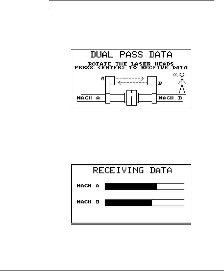
6-30 Acquiring Alignment Data
Note
For the greatest accuracy and repeatability, all readings should
be acquired using the same direction of rotation. In addition, it
is best to use the same direction of rotation as the machine nor-
mally operates.
16
The 8215/8225 laser fixtures are designed to be rotated a full revolution in
two seconds. As with any sweep a good smooth uniform acceleration and
deceleration during the rotation of the laser heads is necessary for accurate,
reliable, and repeatable data. During the transfer, the “Receiving Data”
screen will be displayed showing the progress of the data transfer for each
laser head.
17
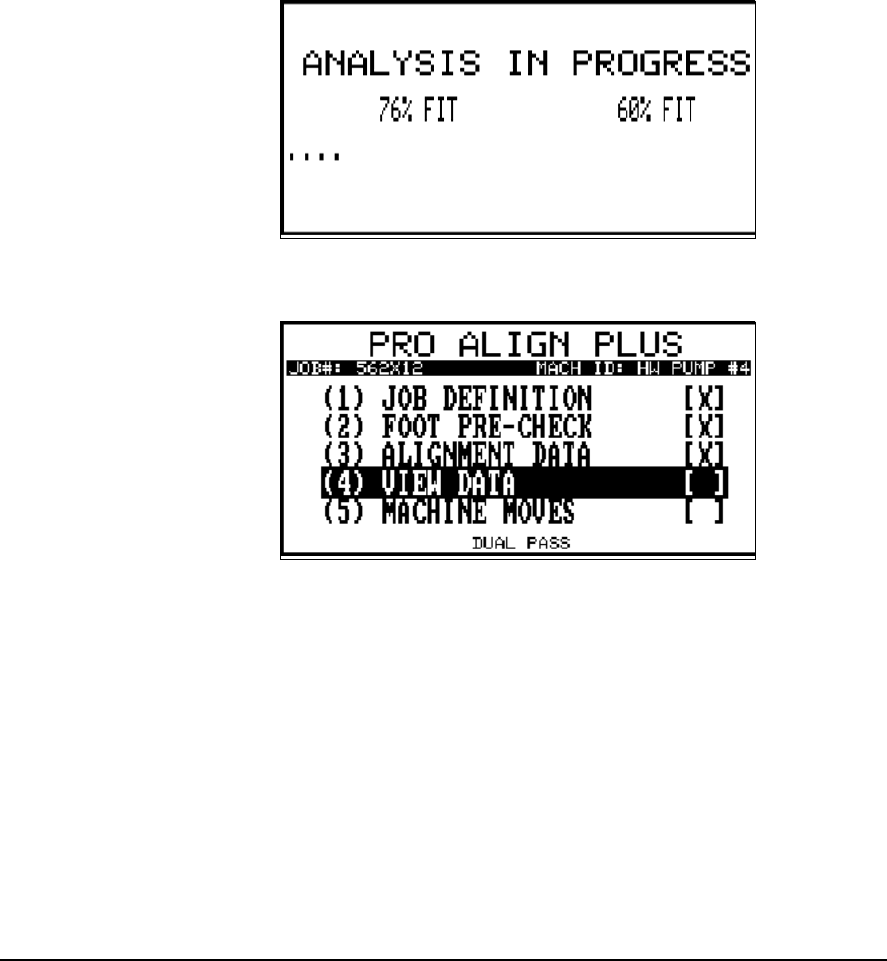
6-31
When the data transfer is completed, an “Analysis In Progress” screen sim-
ilar to the following is displayed while the data is curve fit to a sine wave. If
the fit is satisfactory (85% and above), you are returned to the main menu
where the data may now be viewed.
18
19
Otherwise, you are warned the data is “Unfit” (less than 85%). At this point
you should either repeat the data acquisition or try to manually condition
or edit the data. This built-in check helps alert you to the data losing reli-
ability in the misalignment calculations. Refer to “Additional Data Detail”
on page 5-34 for more information.

6-32 Acquiring Alignment Data
Note
Remember, when shaft movement due to causes other than
misalignment is present in the data this will appear as a ran-
domness (noise) in the data. This is not normally a problem
when the misalignment great, but will increasingly interfere as
the misalignment decreases. Therefore, the better the align-
ment the more likely the chance of seeing the Unfit data
warning.
If you do encounter a machine where this becomes a problem too great to
overcome, consider switching to an alternative method such as Manual
Sweep.

6-33
Quick Spec
Quick Spec
Quick Spec allows you to make a quick check of the alignment condition of
a machine with minimal setup and effort. If a machine is found to have
unacceptable alignment, the procedure can be readily converted to a full
alignment procedure and machine moves calculated.
Quick Spec is only
available in Pro Align and Pro Align Plus
.
To use Quick Spec, select the desired alignment method from the Align-
ment Setup menu which is accessed using the Options key. Then, set Quick
Spec to Yes. When in Quick Spec mode, the normal alignment main menu
is not shown; each new job begins ready to configure and acquire data.
Caution!
Entering Quick Spec mode will clear any existing job in the Current
Job area. A warning screen will give you a chance to cancel this action.
Note
Quick Spec is not available for the Dual Pass method or
straightness.
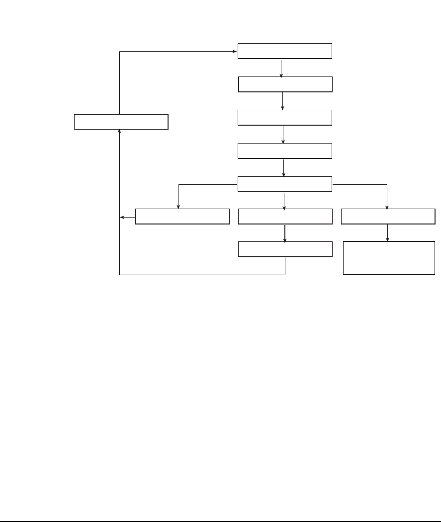
6-34 Acquiring Alignment Data
Quick Spec Mode Flow Diagram
Laser Configuration
Dimensions
Acquire Data
View Data
Action
Take More Data Save Data Align Machine
Define Job Change Job to
Standard Alignment
Procedure
Clear Data
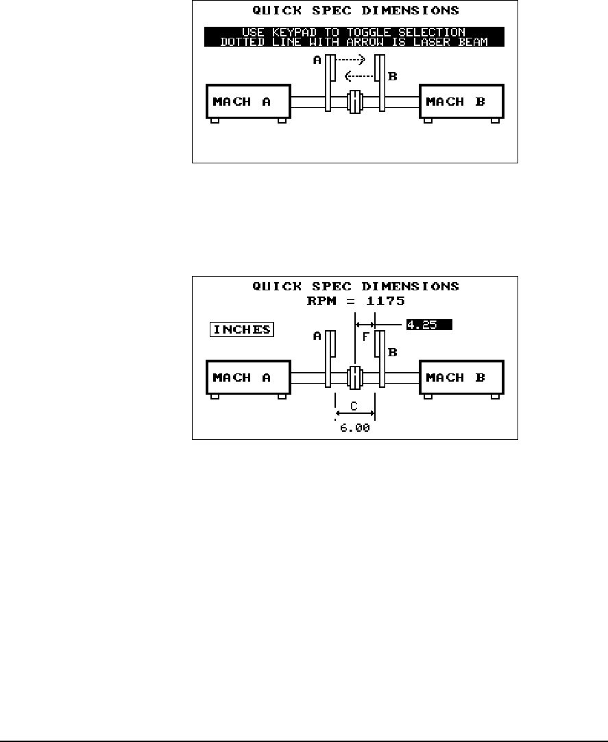
6-35
Quick Spec
20
To check the current alignment condition of a machine, mount the laser
heads on the shafts, then change the display to match the head positions
using any number key to toggle the relative positions. The laser heads are
designated as A and B (this is marked on the face plates).
21
Once the head positions have been designated, press Enter to accept. You
must now enter the machine speed and two dimensions. The distance
between the heads and from the center of the coupling to the head on the
right is all that is required to check the current alignment. When this data
has been entered, press Enter to continue.
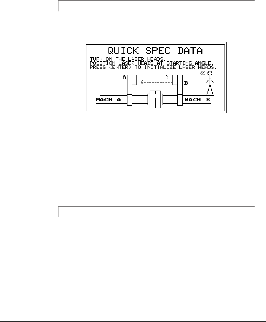
6-36 Acquiring Alignment Data
Note
In this example, Quick Spec uses the Auto Sweep method to
acquire data.
22
The next screen directs you to turn on the laser heads, position them at any
angular position you desire to start from, and then press the Enter key to
initialize the laser heads. It is not required to define a sweep arc range and
direction of rotation due to the increased number of data readings acquired
every 2 degrees and the process, which automatically defines the direction
of rotation. Once the laser heads are initialized the next screen appears
prompting you to now acquire the data by rotating the laser heads. After
the laser heads have been rotated, press the Enter key transmit or transfer
the data from the laser heads to the analyzer.
Note
For the Auto Sweep method, if the laser heads have not been
turned off since they last acquired and stored a set of data read-
ings and prior to initializing them, pressing the Alt/0 (Alt/
Space) key will “Resend” the last set of data they acquired and
stored to the analyzer without having to resweep the laser
heads. This is useful if for some reason the data transfer from
the heads to the analyzer was aborted before it was complete.
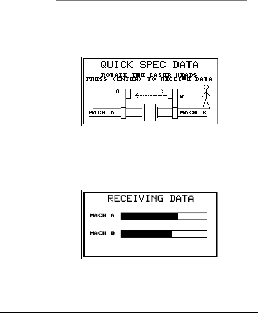
6-37
Quick Spec
Note
For the greatest accuracy and repeatability, all readings should
be acquired using the same direction of rotation. In addition, it
is best to use the same direction of rotation as the machine nor-
mally operates.
23
The 8215/8225 laser fixtures are designed to be rotated a full revolution in
two seconds. As with any sweep a good smooth uniform acceleration and
deceleration during the rotation of the laser heads is necessary for accurate,
reliable, and repeatable data. During the transfer, the “Receiving Data”
screen will be displayed showing the progress of the data transfer for each
laser head.
24
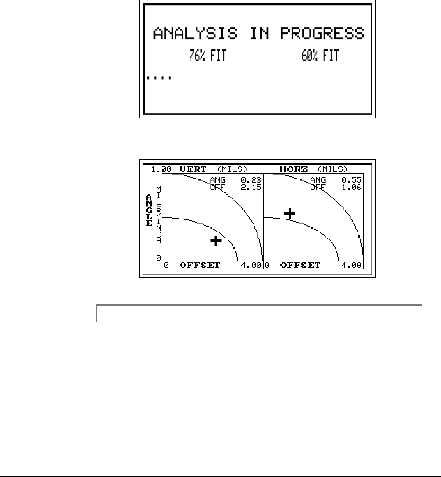
6-38 Acquiring Alignment Data
When the data transfer is completed, an “Analysis In Progress” screen sim-
ilar to the following is displayed while the data is curve fit to a sine wave. If
the fit is satisfactory (85% and above), you are shown the results by means
of a dual tolerance plot screen.
25
26
Note
For users who want to view the acquired data in more detail,
pressing the Page Down key when the dual tolerance plot is
displayed will access additional screens. Refer to “Additional
Data Detail” on page 5-34 for more information.
Otherwise, you are warned the data is “Unfit” (less than 85%). At this point
you should either repeat the data acquisition or try to manually condition
or edit the data. This built-in check helps alert you to the data losing reli-
ability in the misalignment calculations. Refer to “Additional Data Detail”
on page 5-34 for more information.
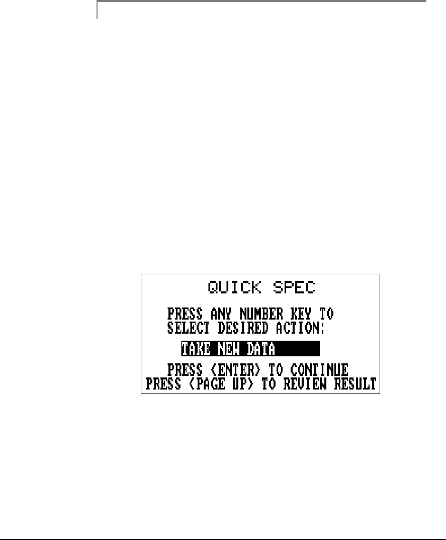
6-39
Quick Spec
Note
Remember, when shaft movement due to causes other than
misalignment is present in the data this will appear as a ran-
domness (noise) in the data. This is not normally a problem
when the misalignment great, but will increasingly interfere as
the misalignment decreases. Therefore, the better the align-
ment the more likely the chance of seeing the Unfit data
warning.
If you do encounter a machine where this becomes a problem too great to
overcome, consider switching to an alternative method such as Manual
Sweep or 4 Point Auto.
After viewing the dual tolerance plot, press Enter to store the reading and
continue. You now have a choice to either take more data using Quick
Spec, save this data, or align the machine. Either use any Number key on
the keypad to toggle between these choices, and then press Enter to accept
the choice; or press the Page Up key to review the results (dual tolerance
plot).
27
Selecting “Take More Data” will clear the previous readings and return you
to the start of the Quick Spec routine.
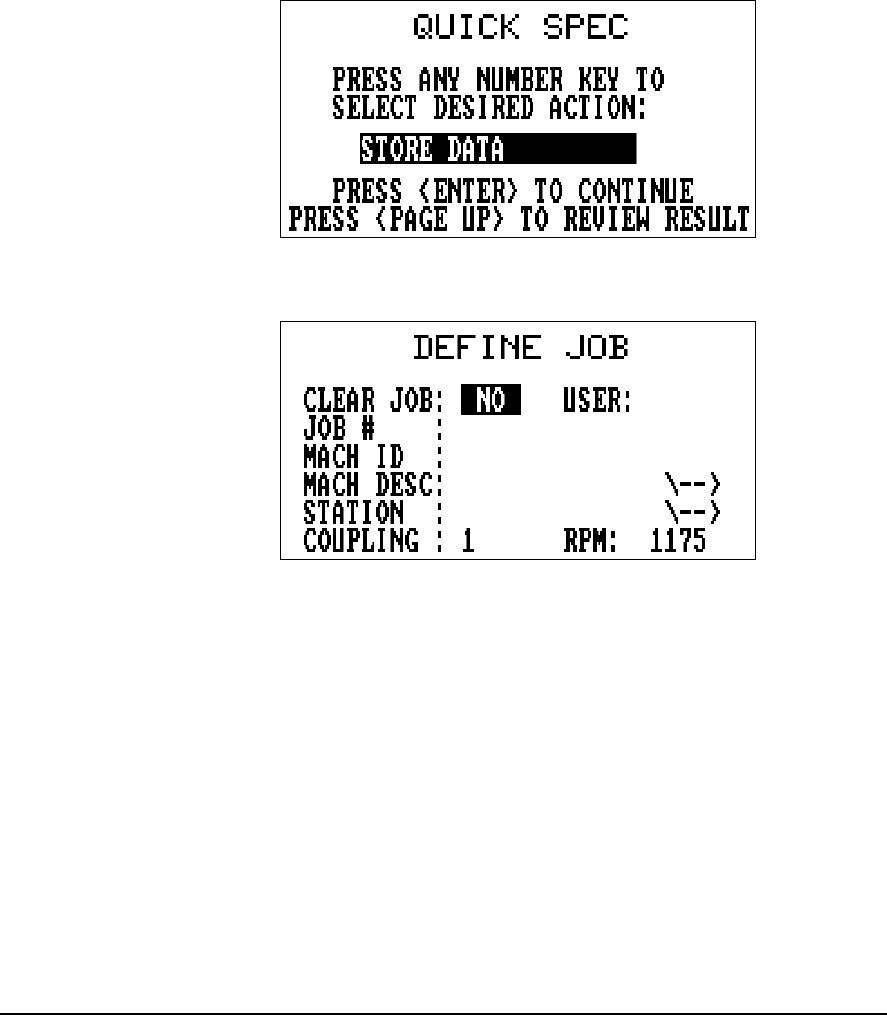
6-40 Acquiring Alignment Data
Saving Quick Spec Data – if you want to save this data and the job, select
“Store Data.”
28
The Define Job screen will then be displayed.
29
A Job # must be supplied before storing the job. You can also add other
descriptive information (identifying the machine) at this time, if desired.
If this Quick Spec job was recalled from the stored job area, the previously
entered data will be present. After all changes to this screen are complete,
press Enter to save the job. If the job is stored successfully, a screen appears
stating that it was a success. Also displayed on this screen is the amount of
“Free Memory” (in bytes) available in the analyzer.
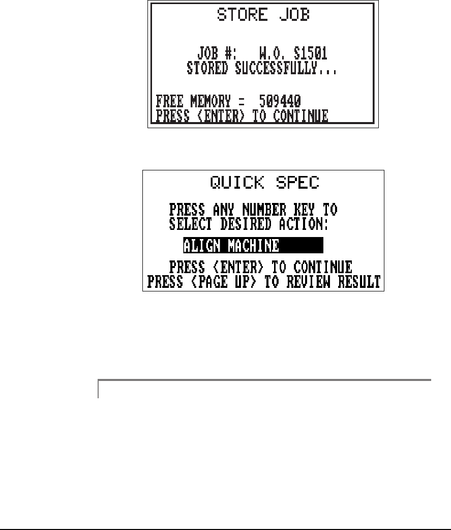
6-41
Quick Spec
30
Press Enter to continue and return to the initial Quick Spec Screen.
31
Using Quick Spec data to align a machine – selecting Align Machine
takes you directly into the normal alignment mode. To return to Quick
Spec, simply clear the current job. If you wish to calculate the moves, then
complete the job definition and go directly to the Machine Moves selection.
Note
If soft foot has not been corrected previously on this machine,
you will want to check for soft foot before making any moves.
If a soft foot is corrected after the Quick Spec data was taken,
you will want to take a new set of alignment data from which
to calculate the moves.

6-42 Acquiring Alignment Data
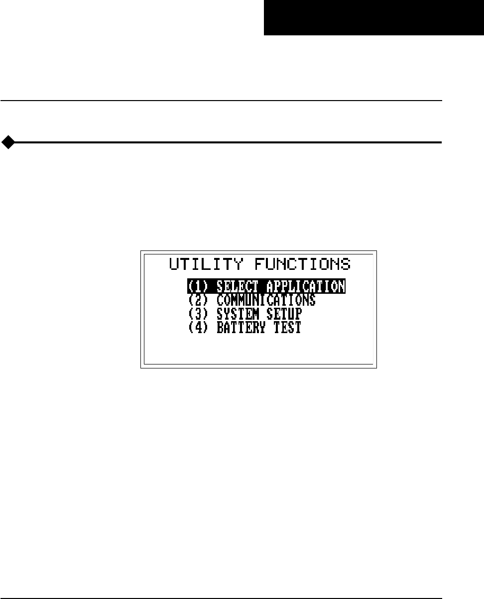
Chapter
7-1
7
Straightness Application
Overview
The straightness feature found in the UltraSpec analyzer alignment appli-
cation is used to determine surface profiles. This profile can be of a motor
baseplate or checking the crown on a rolling application. You must use a set
of laser sensor heads and mounting fixtures (CSI model 8AA50) to acquire
surface profile readings.
1
14
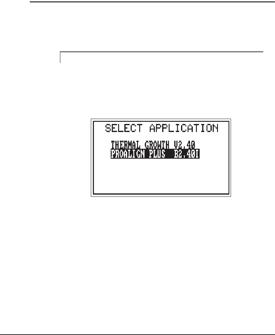
7-2 Straightness Application
Select the Application
To select the straightness method of data collection, the UltraSpec
analyzer
must be in the alignment application. Press the Utility function key and
press the Enter key when the selected application is highlighted.
Note
If already in the alignment application, this step and the next
are not required.
The following screen is displayed.
2
Select PRO ALIGN PLUS and press the Enter key.
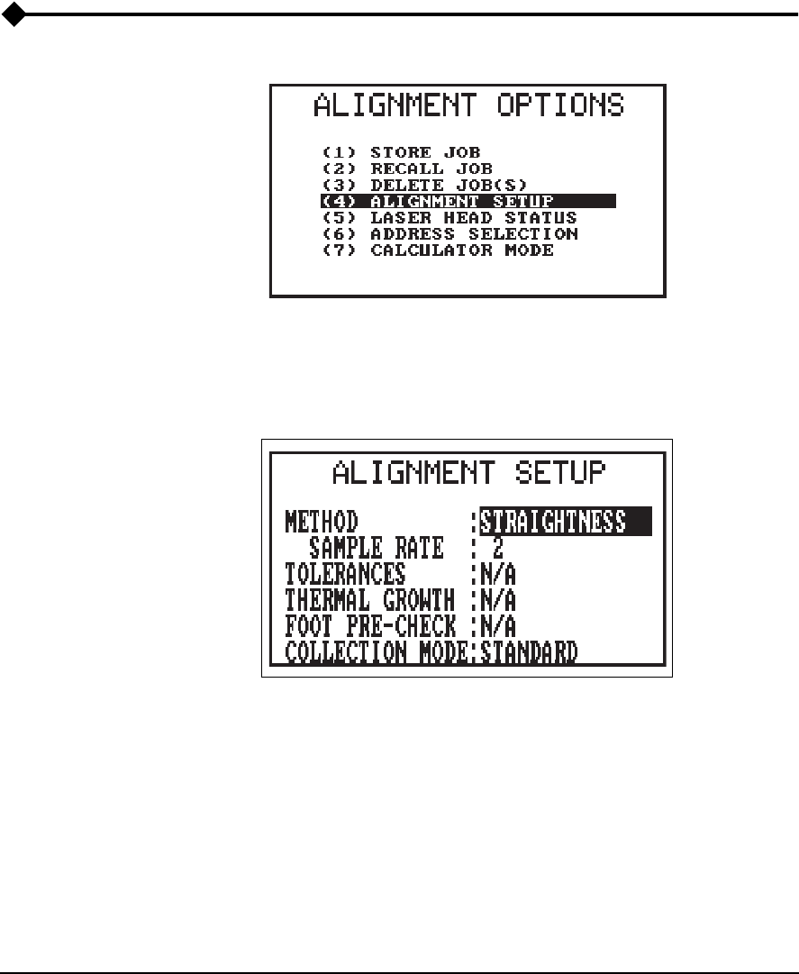
7-3
Alignment Setup
Alignment Setup
3
From the alignment application's main menu, press the Options function
key. Arrow the selection bar to Alignment Setup and press the Enter key.
The following screen is displayed.
4
Use any Number key to toggle through the selections for method until
straightness is displayed. Once this method is shown, use the Up and Down
Arrow keys to make a selection, and any Number key to toggle through the
options for that selection. If necessary, use these keys to set the Sample rate
and Collection mode.
•
Sample Rate –
determines the number of data samples that are to
be collected and averaged together to produce a single Laser PSD
reading. Use the Left and Right Arrow keys to toggle sample rate
from 1 to 25 samples. The default is 2.
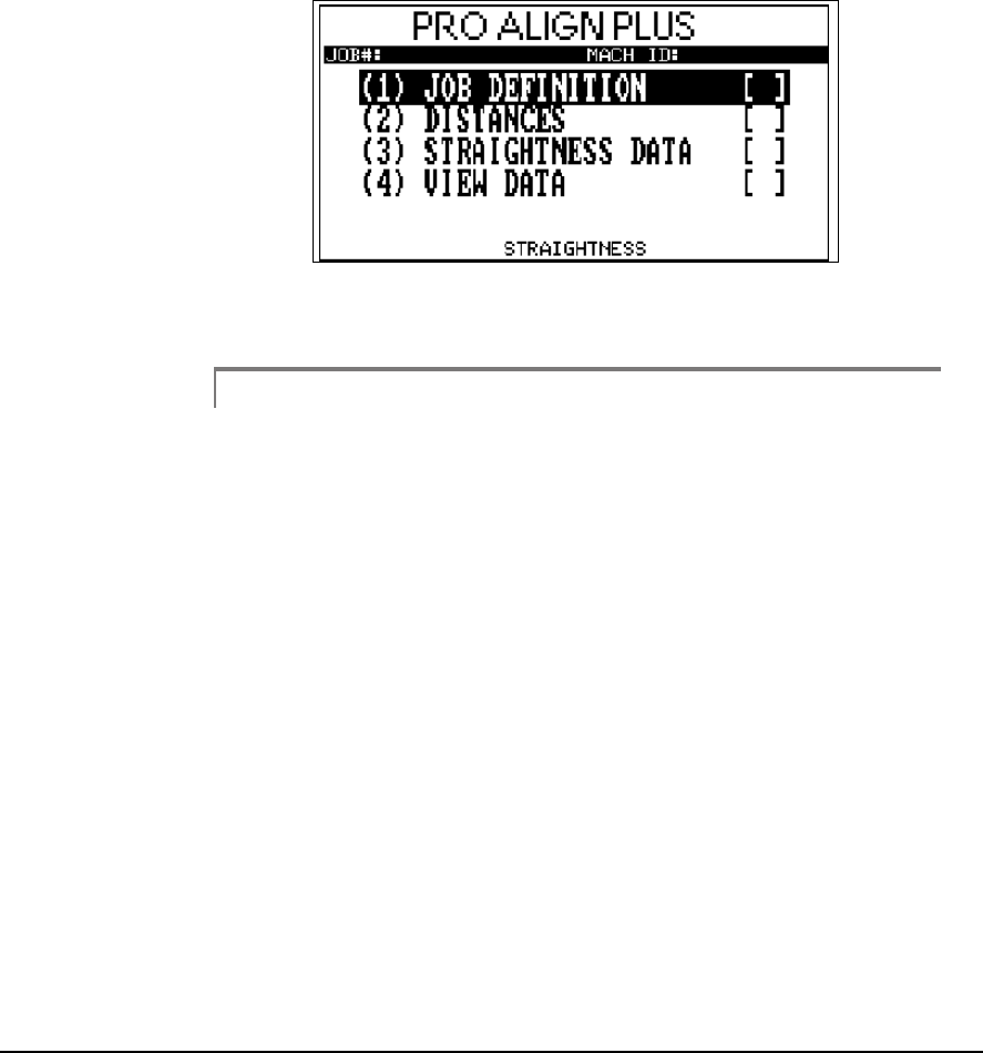
7-4 Straightness Application
•
Collection Mode –
select Standard for a continuous reading of the
Laser Readings (the current or last reading is used), or select Average
for a continuous accumulative average of the laser readings.
The straightness method main menu will now be displayed.
5
Highlight Job Definition, and press the Enter key.
Note
Notice that the method (straightness) is shown at the bottom,
center.
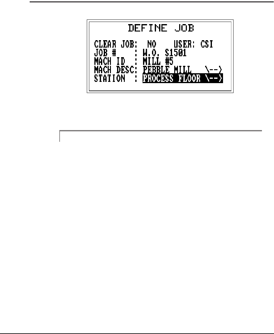
7-5
Alignment Setup
Defining the Job
6
On this screen, enter the requested information using the alphanumeric
keypad.
Note
All
the information is required for proper job documentation.
Press the Enter key when the information has been filled in.
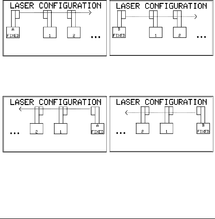
7-6 Straightness Application
Four Ways of Configuring the Laser Fixtures
There are four ways to configure the laser fixtures. The first consideration
is which fixture is to be fixed and which one will be moved. The configura-
tion shown below is for the left fixture to be fixed. Notice the laser head to
be used at each location can also be selected.
7
The other two configuration options are shown below. This arrangement
has the right fixture fixed.
8
This selection process is accomplished by toggling through the available
options with any number key.
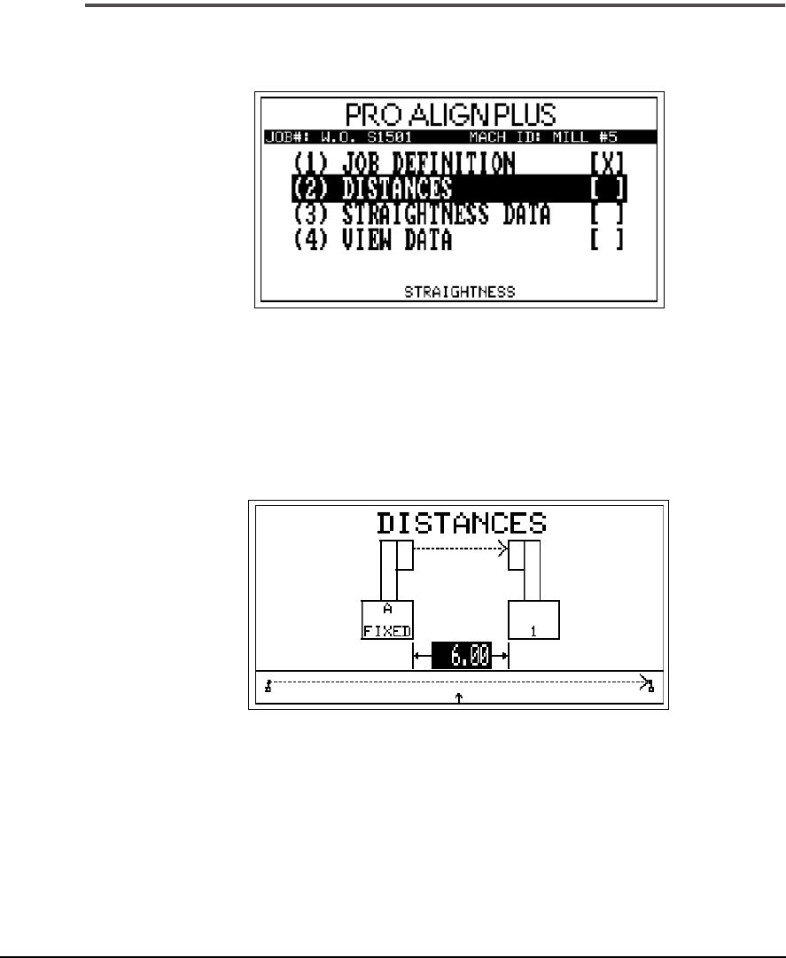
7-7
Alignment Setup
Entering Distances
9
After the job definition step has been completed, an “X” is placed beside
that step indicating it has been completed. With Distances highlighted,
press the Enter key.
The following screen is displayed.
10
Enter the distance (in inches) between the fixed head and the first measure-
ment location. To add additional measurement segments, press the Up
arrow key. The distance between the segments can be different lengths and
up to 50 segment measurements can be taken. Segments of the same length
can be entered by pressing the Up arrow key.
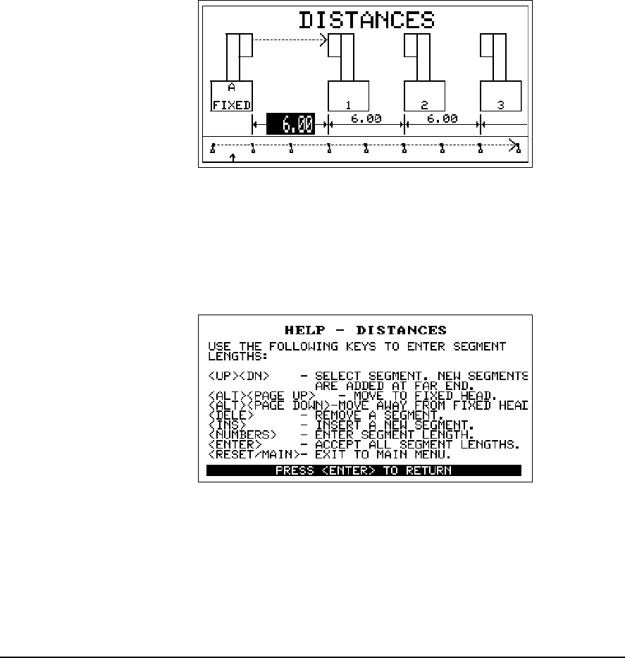
7-8 Straightness Application
The distance screen will show up to four measurement locations at one
time. Notice that a total of eight measurement segments have been defined
in this example and the first segment field is active. This information is dis-
played on the overall graph below the segment fields. The arrow shows the
present location.
11
Help Messages
Help messages are available in any of the UltraSpec applications by
pressing the Help function key. The help message for the distance screen is
displayed to show the active keys for entering information.
12
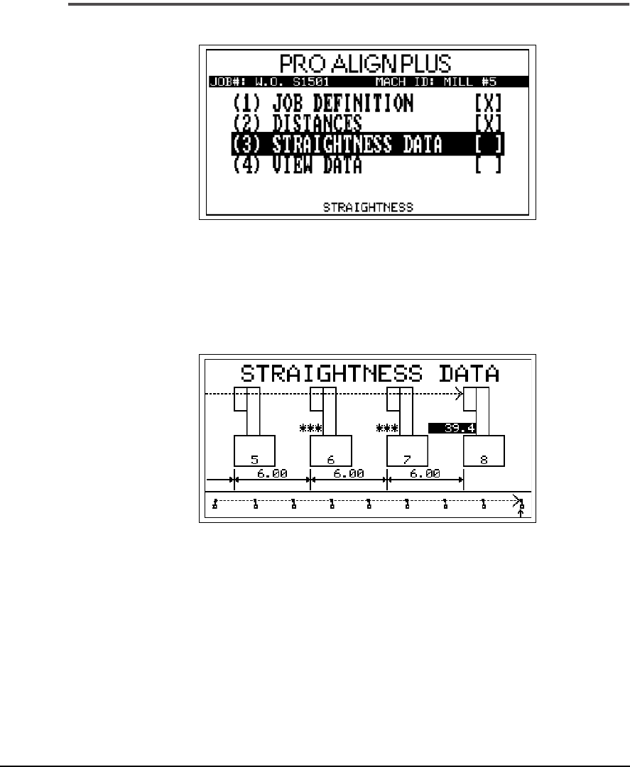
7-9
Alignment Setup
Taking Straightness Data
13
Again, an “X” has been placed in Step 2 showing completion. Highlight
Step 3, Straightness Data, and press the Enter key.
The following screen is displayed.
14

7-10 Straightness Application
Turn the lasers on. To disable the sleep mode on each laser head, hold the
power button down for 3 seconds, until the activity LEDs are both off.
Laser communications with the moveable head must be established to col-
lect data at the defined segments. Communication can be with radio fre-
quency (RF) or cable. Start at the farthest point and center both lasers. To
accept the value displayed, press any number key. Use the Up arrow key to
move to the next segment to the right. Use the Down arrow to move to the
left.
The moveable sensor head is then relocated to the next measurement
point. It should be positioned so that the beam from the
stationary
head is
horizontally centered in the
moveable
heads target. If it is not within a band
± 10 mils of the center vertical axis, the error message “Beam horizontally
off enter” will be displayed. To remove the message, readjust the moveable
sensor head. A reading can be deleted and retaken by selecting that seg-
ment and pressing the Delete key.
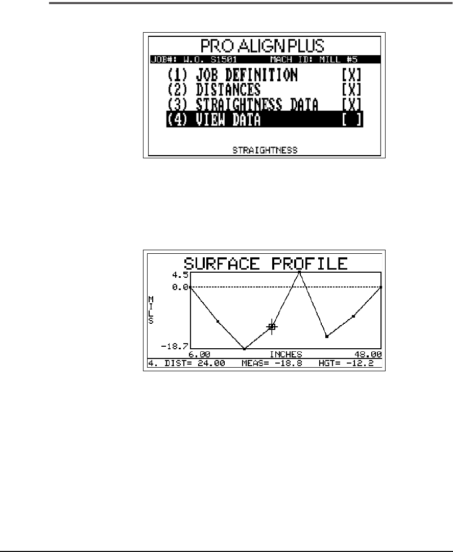
7-11
Alignment Setup
View Data
15
Once all the readings are taken, press the Enter key to accept all the data.
Step 3 has an “X” showing completion and step 4 is highlighted. Press the
Enter key to view the results of the profile.
16
The surface profile for the eight segments measured is displayed. A cursor
can be moved using Left or Right arrow keys to display information on an
individual segment. The segment number, length, measured value and
height from the laser (dotted line) is shown on the bottom. Press the Enter
key to return to the main menu.
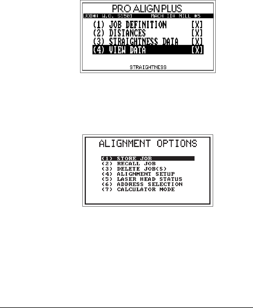
7-12 Straightness Application
17
An “X” now appears next to step 4 indicating completion of the current
straightness job. To save the current job information press the Options func-
tion key.
The following screen is displayed.
18
Choose Store Job and press the Enter key.
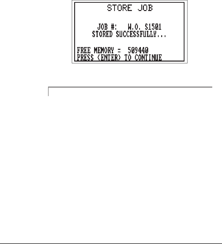
7-13
Alignment Setup
If no duplicate job numbers were previously stored, the screen below will
be displayed.
19
You can now transfer the job data to UltraMgr for long-term storage.
Note
For additional information on storing a job, recalling a job, and
deleting a job refer to “Options Key” on page 3-2 for details.
For information on printing, refer to “Screen/Print Key” on
page 3-25 for details.

7-14 Straightness Application
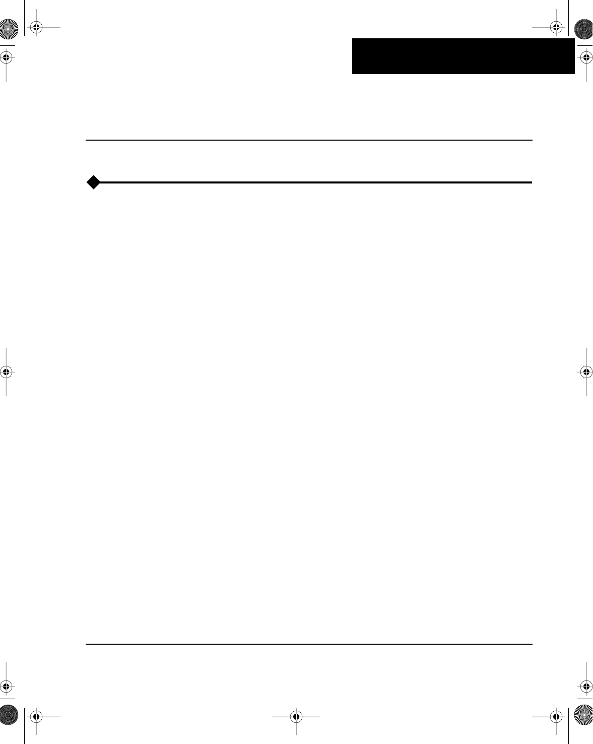
Chapter
8-1
8
Application Information
Machinery Shaft Alignment – General Overview
Poor shaft alignment can cause the following problems:
• Bearing failure
• Shaft deflection fatigue
• Seal leakage and failure
• Coupling failure
• Internal heating
• High energy consumption
• Excessive vibrations (studies have shown that almost 50% of exces-
sive vibration in direct-coupled rotating equipment is due to mis-
alignment)
Proper machine alignment will result in:
• Less downtime (increased production)
• Increased bearing life
• Lower energy costs
• Increased coupling life
• Lower vibration (lower maintenance costs, even on surrounding
machinery)
A successful alignment job involves completing at least five major steps:
• Pre-job preparation and setup (considering items such as soft foot,
base integrity, pipe strain, documentation, and tolerances)
• Measurement of the amount and direction of misalignment
• Calculating corrective moves
• Actually moving the equipment within preset tolerances
8
Chapter 8 Page 1 Friday, January 26, 2001 10:34 AM
8-2 Application Information
• Documentation of work done for use in future alignment jobs
Early alignment methods involved using a straightedge along the coupling
rims. This is still a good procedure to use as a preliminary step. In fact, for
low speed machines, operated infrequently for short periods of time, it may
be all that is needed.
However, more complex machines require more than this. Feeler gages,
inside micrometers, and dial indicators are now used extensively for taking
precise alignment measurements and monitoring corrective moves. These
tools can give good results when used properly.
Mistakes, however, can cause errors in the alignment procedure. Errors
that commonly occur are:
• Failing to document the job setup, problems, findings, and data
• Failing to use good indicator brackets
• Failing to determine the correct amount of bracket sag
• Misreading the indicators
• Failing to detect sticking indicators
• Mistakes in recording and interpreting the data
• Errors in calculating the moves
• Errors in making moves
These types of errors are even more likely to occur when you have pressure
to complete the job quickly.
CSI’s alignment equipment can help you avoid these kinds of mistakes.
Our adjustable brackets are designed to fit most machines. Since there are
no axial projecting arms, bracket sag is zero. Misalignment readings are cal-
culated automatically and required moves are then displayed. If a serious
mistake is made, the system will prompt you for corrected entries before
moving on to the next step.
Completed jobs are easily documented. Documented jobs can then be
stored in UltraMgr, a PC-based, corrective technologies information man-
agement system. This documented history can be used to enhance trouble-
shooting, identify personnel candidates for additional training, reduce
alignment time, etc. See “UltraMgr” on page 8-8 for more information.
Chapter 8 Page 2 Friday, January 26, 2001 10:34 AM
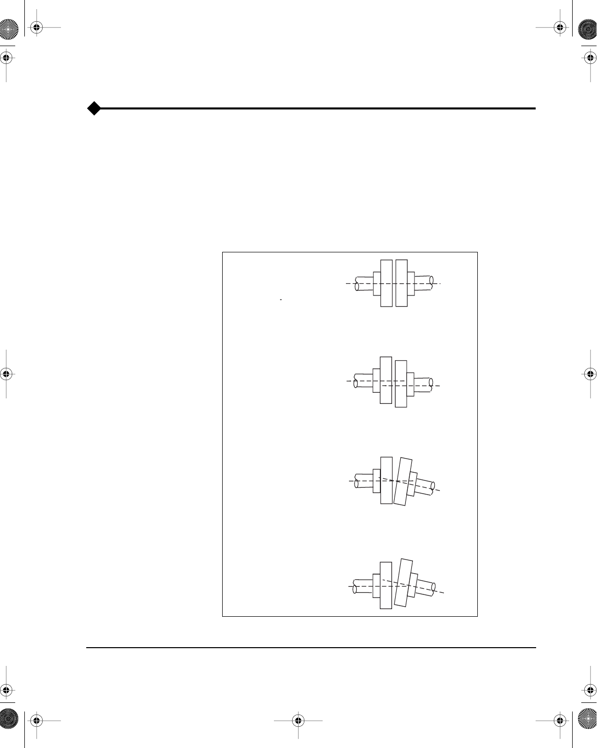
8-3
Alignment Application Notes
Alignment Application Notes
To achieve ideal machine alignment, the shaft centerline of one machine
element (such as a motor) must coincide with the centerline extension of
another machine shaft (such as a pump) during operation. In more complex
applications, three or more elements may be aligned in a train.
Misalignment can occur both horizontally and vertically. Most misaligned
machines have a combination of offset and angular misalignment (see fol-
lowing figure).
Alignment Examples
Proper
Alignment
Offset
Misalignment
Angular
Misalignment
Combination:
Offset and Angular
Misalignment
Chapter 8 Page 3 Friday, January 26, 2001 10:34 AM
8-4 Application Information
Pre-job Preparation and Setup
Before starting any alignment job, the history of alignments performed on
this machine(s) should be reviewed. Were any special problems found
during the previous alignment; if so, what were they (soft foot, piping strain,
coupling problems, etc.)? How well was the machine aligned and who per-
formed the alignment? Answering these questions along with having a pre-
defined job setup reduces the pre-job preparation time and decreases the
total time to do the job.
Now that the past is known, before proceeding with alignment measure-
ments, ensure that your machine(s) are mounted perfectly parallel with the
base or foundation. If they are not parallel, additional stress may be placed
on the machine when the anchor bolts are tightened. Uneven height of the
base surface, dirt or corrosion under the feet, or other irregularities can all
cause the machine to be supported unevenly – a condition known as “soft
foot”. In addition to preventing proper machine alignment, extreme soft
foot conditions can actually cause damage to the machine (warped or
cracked feet, etc.).
Two major reasons for correcting soft foot are (1) to avoid “chasing your
tail” during the alignment and (2) to remove the stress and enable the
machine(s) to operate at their best. Therefore, all machines should be
checked for soft foot, not just the machine being moved.
Additional pre-alignment considerations include:
• Proper foundation
• Grouting (suitable material with no voids or cracks)
• Baseplate (must be clean, rigid, and properly designed)
• Coupling (properly selected and installed)
• Machinery element supports (no cracks and tight)
• Minimize pipe strain
Chapter 8 Page 4 Friday, January 26, 2001 10:34 AM
8-5
Alignment Application Notes
Proper Foundation
On new installations, allow foundation concrete to cure sufficiently before
installing your machines. Normally, you should not mount machines
directly on the foundation. Base plates usually provide more stability. Also,
to make future alignments easier, a set of high quality (stainless steel, etc.)
pre-cut shims should be placed beneath each foot. These should be at least
1/8 inch (3 mm) thick.
Coupling Considerations
CSI’s alignment system is not affected by axial float and the effects from
torsional play (backlash) in the coupling are minimal. However, you should
ensure that the coupling is properly installed and not in such poor condition
that it adversely affects the alignment process. Also, CSI recommends
(while alignment is being performed) that you eliminate torsional play by
rotating the driving machine in the same direction that it normally operates.
If necessary, put a drag on the driven end to prevent gravity overswing.
Minimize Pipe Strain
Excessive pipe strain can create serious problems and should be corrected
before attempting machine alignment. Ensure that pipes are fitted correctly
and, if necessary, have some flexibility. In some cases, stationary pipes
fitted directly to the machine can cause machine movement as they heat up
(thermal growth).
Changes That Occur During Operation
Machine alignment can change significantly as machines are started from a
“cold” position and run up to operating speed (“hot” position). Some factors
that can influence alignment include:
• Thermal growth
• Torque transmission forces
• Aerodynamic forces
• Hydraulic forces
Chapter 8 Page 5 Friday, January 26, 2001 10:34 AM
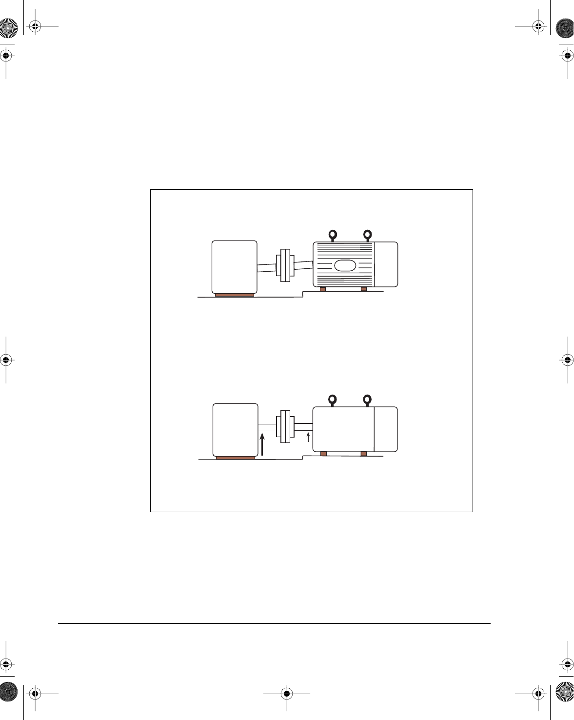
8-6 Application Information
Thermal Growth
Unfortunately, machines that must be aligned may not expand thermally at
the same rate. Because of this, you may have to intentionally misalign them
in their “cold” positions in order to achieve alignment when they are “hot”.
The following drawing shows an example of this.
Different Thermal Expansion Rate Examples
The UltraSpec alignment system allows you to input the amount of vertical
and horizontal thermal growth at each machine foot. There are several
methods that can be used to calculate this growth.
Cold machines intentionally misaligned
Machines properly aligned after reaching operating temperature
Motor
Small
Expansion
Large
Expansion
Gearbox
Chapter 8 Page 6 Friday, January 26, 2001 10:34 AM
8-7
Alignment Pitfalls
Alignment Pitfalls
Some pitfalls to good alignment are:
• Improperly or not correcting for soft foot
• Thermal growth
• Excessive shaft play or radial clearances
• Bent shafts
• Damaged bearings
• Torsional play
Chapter 8 Page 7 Friday, January 26, 2001 10:34 AM
8-8 Application Information
UltraMgr
UltraMgr is a versatile, PC-based, database software package that is used to
manage corrective technologies data. UltraMgr is designed to communi-
cate with the UltraSpec analyzer and other CSI analyzers.
The storage of alignment information in a database provides many advan-
tages which include:
• The ability to quickly retrieve and review the alignment status of all
equipment in an entire plant to help plan the maintenance priorities
and scheduling.
• The ability to quickly retrieve and review the alignment history of a
particular technician to determine if more training is needed.
• The ability to quickly retrieve and review the alignment history of a
particular piece of equipment to determine if the machine is going
out of alignment too frequently.
• The ability to use previously entered and stored machine-specific
data and setup information in the present alignment (on the same
machine) thereby greatly reducing setup time.
• The ability to use previously entered and stored machine-specific
data and setup information in the present alignment (on a similar
machine), thus requiring only minor changes in the field.
• The ability to recall the complete alignment job previously per-
formed on the present machine (including notes) to see peculiarities
that might affect alignment. Knowing about previous problems will
reduce time spent tackling the same concerns. Also, the name of the
technician that performed the alignment previously is available in
case there are any questions.
UltraMgr can be used as a standalone program or in conjunction with CSI’s
RBMware. The maximum benefits of UltraMgr are obtained when used
with RBMware because you can quickly switch from alignment history to
examine vibration data for machines under investigation.
Chapter 8 Page 8 Friday, January 26, 2001 10:34 AM

Chapter
9-1
9
System Maintenance and Troubleshooting
Overview
In this chapter, for your convenience, we have grouped many of the various
activities related to maintaining and troubleshooting the UltraSpec Laser
Alignment system. In some cases, the actions are also discussed in other
parts of the manual. CSI hopes this will help you quickly find maintenance-
related information when you need it.
Firmware and Application Version
This manual covers UltraSpec 8215/8225 compatible analyzer firmware
and application versions 2.40 (and later). Version 2.40 (and later) firmware
and applications require version 6.0 or later ROM to load into the
UltraSpec analyzer.
Note
The 8215/8225 Laser Fixtures are only compatible with the
ProAlign Plus application and not compatible with the
ProAlign, Easy Align, Quick Align, Vertical Align, and Train
Align applications.
UltraSpec Analyzer Serialization
The loaded firmware has been serialized and is matched to the analyzer
serial number. If the firmware and analyzer serial numbers do not match,
contact CSI Customer Support.
22

9-2 System Maintenance and Troubleshooting
UltraMgr Software and Prerequisites
In order to use the UltraSpec 8215/8225 compatible 2.40 applications with
UltraMgr compatible software, the software must be RBMware version
4.40 or later for Windows.
DOS UltraMgr software and earlier versions of Windows UltraMgr soft-
ware will not work with the UltraSpec 8215/8225 compatible analyzer 2.40
or later applications.
Note
The UltraSpec Thermal Growth application will note commu-
nicate with the UltraMgr software.
Note
UltraMgr requires some planning and set up before jobs can be
downloaded into the UltraSpec analyzer. See the UltraMgr
User’s manual for more information.

9-3
Precautions
Precautions
Please follow these precautions carefully. Any product damage due to these
conditions may void the warranty.
•
Do not
change the battery pack with the battery charger connected as
damage may occur to the analyzer.
• Use only CSI-supplied battery chargers that have been approved for
use with the UltraSpec analyzer and 8215/8225. The use of any other
charger will most likely damage the equipment.
• Do not use CSI battery chargers with anything other than what they
are designed for! The 8211
must
be used to charge the UltraSpec ana-
lyzer and 8215/8225; do not use the 8211 to charge anything else!
• Do not repeatedly overcharge the analyzer batteries. If the batteries
are continually allowed to remain in the “Fast” charge cycle for
periods longer than the recommended 14 to 16 hours, battery degra-
dation will occur.
• Do not use any batteries other than those included and/or specified
for the UltraSpec analyzer and 8215/8225.
• Do not connect a signal larger than ± 21 volts into the input of the
analyzer.
• Do not connect any signal other than a TTL-level signal to the
tachometer input. Other signals may damage the analyzer.
• Do not connect a printer directly to the RS232 port located on the
top panel of the analyzer.
• Do not connect any adapters or accessories to the RS232 port
located on the top panel of the analyzer while the analyzer is turned
on.
• Do not start the machines being aligned with the laser alignment
system equipment attached. Be sure to remove the laser system
before starting the machinery.

9-4 System Maintenance and Troubleshooting
UltraSpec Analyzer Battery Maintenance
UltraSpec Analyzer Battery
A rechargeable battery pack is used to power the UltraSpec analyzer.
Before using the analyzer, verify that the battery has enough charge to
operate properly.
The battery needs to be recharged if:
• The analyzer will not power up; or
• The analyzer displays a low battery warning and turns itself off.
Continuous Battery Operation Length
With a fully charged battery, the UltraSpec 8000 analyzer will operate con-
tinuously for at least ten hours and the UltraSpec 8117 will operate contin-
uously for at least eight hours. The actual time between recharge cycles can
be increased by turning the analyzer off when not in use.
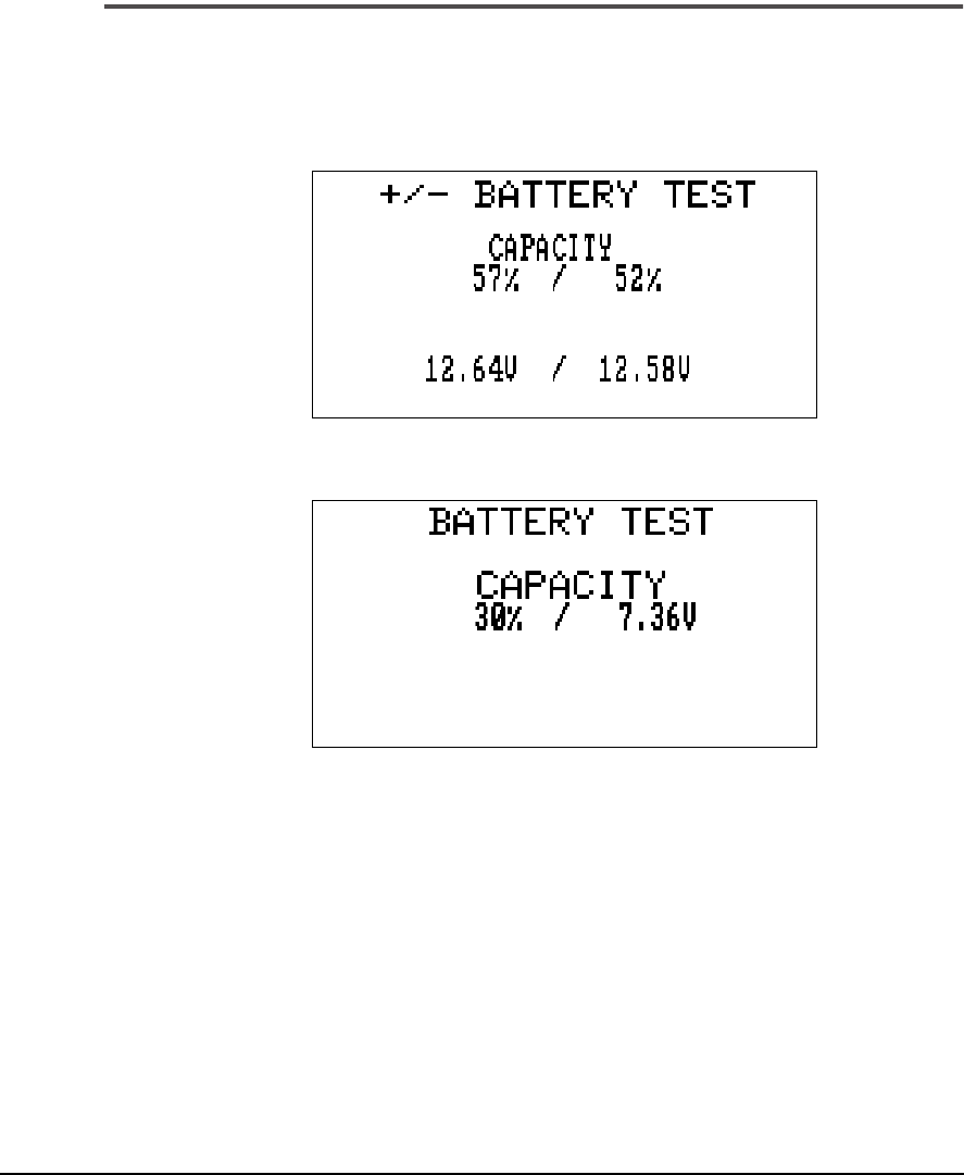
9-5
UltraSpec Analyzer Battery Maintenance
Battery Test
The Battery Test function will give an approximate indication (in percent)
of the battery’s condition and the battery pack voltage. To access this func-
tion, select Battery Test from the Utility key menu.
UltraSpec 8000
UltraSpec 8117
This display presents
approximate
values and should only be used as a guide-
line in determining the amount of battery charge remaining. When the per-
cent value first reaches zero, a built-in safety margin allows approximately
ten minutes of additional use before the analyzer turns itself off in order to
protect the memory.

9-6 System Maintenance and Troubleshooting
Note
If the analyzer should display the low battery warning screen
and turn itself off, the analyzer’s memory will remain intact for
approximately two weeks. Therefore, the collected data are
retained in memory and can be accessed after the analyzer’s
battery has been recharged.
UltraSpec 8000 Analyzer Battery Recharge
To recharge the battery, set the “Trickle/Fast” switch on the underside of the
Model A2115-C battery charger to “Fast.” Plug the charger into a standard
115 VAC outlet, and then plug the charger jack into the battery charger
input located on the top panel of the UltraSpec 8000 analyzer.
The supplied battery charger will completely recharge the battery pack in
14 to 16 hours using the Fast setting. If the batteries are continually allowed
to remain in the Fast charge cycle for periods longer than 14 to 16 hours,
battery degradation
will
occur. An occasional overcharge will not signifi-
cantly reduce battery life; however, leaving the batteries in the Fast charge
cycle over a weekend, for example, is not recommended. Typically, the bat-
teries should be placed in the charge cycle (after the analyzer has been used
for a full shift, for example), allowed to charge overnight, and then removed
from charge the next morning.
After the battery has been fully charged, the Trickle charge cycle can be
used to maintain the batteries in a fully charged condition. The Trickle
mode can also be used to charge the batteries over an extended period of
time. The batteries may remain in the Trickle mode for extended periods
without damage.
Note
Optional accessories that provide alternative charging
methods are available for the UltraSpec 8000 analyzer, see
“Accessories and Product Options.”
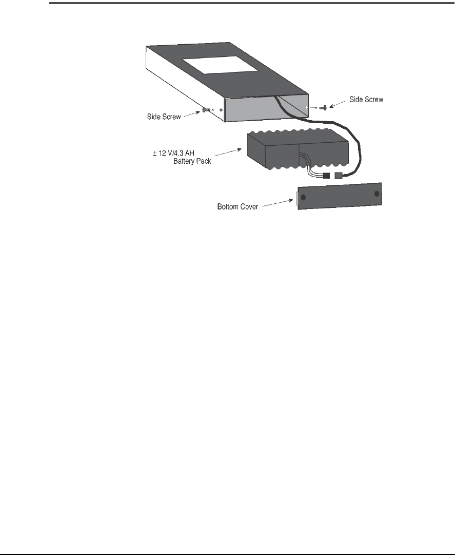
9-7
UltraSpec Analyzer Battery Maintenance
Changing the UltraSpec 8000 Analyzer Battery
Removing the Battery
To change the battery pack:
1. Insure that the analyzer is Off, and that the battery charger is
not
connected to the analyzer.
2. Remove the two screws on the
sides
of the analyzer located just above
the bottom edge (
not
the screws on the bottom cover), and remove
the bottom cover.
3. Carefully remove the battery pack from the analyzer case, and
disconnect the 3-pin connector.
4. Connect the 3-pin connector from the new battery pack to the
analyzer, and insert the battery pack into the analyzer case. Insure
that the connector is placed on top of or beside the battery pack –
not on the bottom side.
5. Replace the bottom cover and screws (the top of the analyzer cover
fits into the slotted side of the cover).

9-8 System Maintenance and Troubleshooting
Note
If the battery is hard to pull out, you may have to remove the
front cover of the analyzer. To do so, carefully slide the cover
downward until the cable connector is exposed. Disconnect
the cable and slide the cover on down until the battery is free.
After replacing the battery, reverse the process by sliding the
cover back up until the cable can be re-attached. Continue by
returning the cover to its original position.
Caution!
Do not change the battery pack with the battery charger connected as
damage may occur to the analyzer. Exercise caution when re-connecting
the 3-pin, polarized connector. Damage will occur to the connector if
forced in the incorrect orientation.
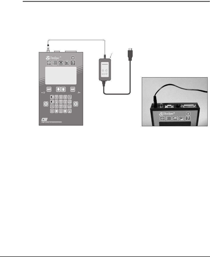
9-9
UltraSpec Analyzer Battery Maintenance
UltraSpec 8117 Analyzer Battery Recharge
To recharge the battery, plug the Model 93140 charger into a standard 115
VAC outlet, and then plug the charger jack into the battery charger input
located on the top panel of the UltraSpec 8117 analyzer.
1
The supplied battery charger will completely recharge the battery pack in
14 to 16 hours. If the batteries are continually allowed to remain in the
charge cycle for periods longer than 14 to 16 hours, battery degradation
will
occur. An occasional overcharge will not significantly reduce battery life;
however, leaving the batteries in the charge cycle over a weekend, for
example, is not recommended. Typically, the batteries should be placed in
the charge cycle (after the analyzer has been used for a full shift, for
example), allowed to charge overnight, and then removed from charge the
next morning.
The UltraSpec 8117 analyzer, with a fully charged battery, will operate con-
tinuously for at least eight hours. The actual time between recharge cycles
can be increased by turning the analyzer off when not in use.
power
supply
to AC
wall outlet
AC Power Adaptor
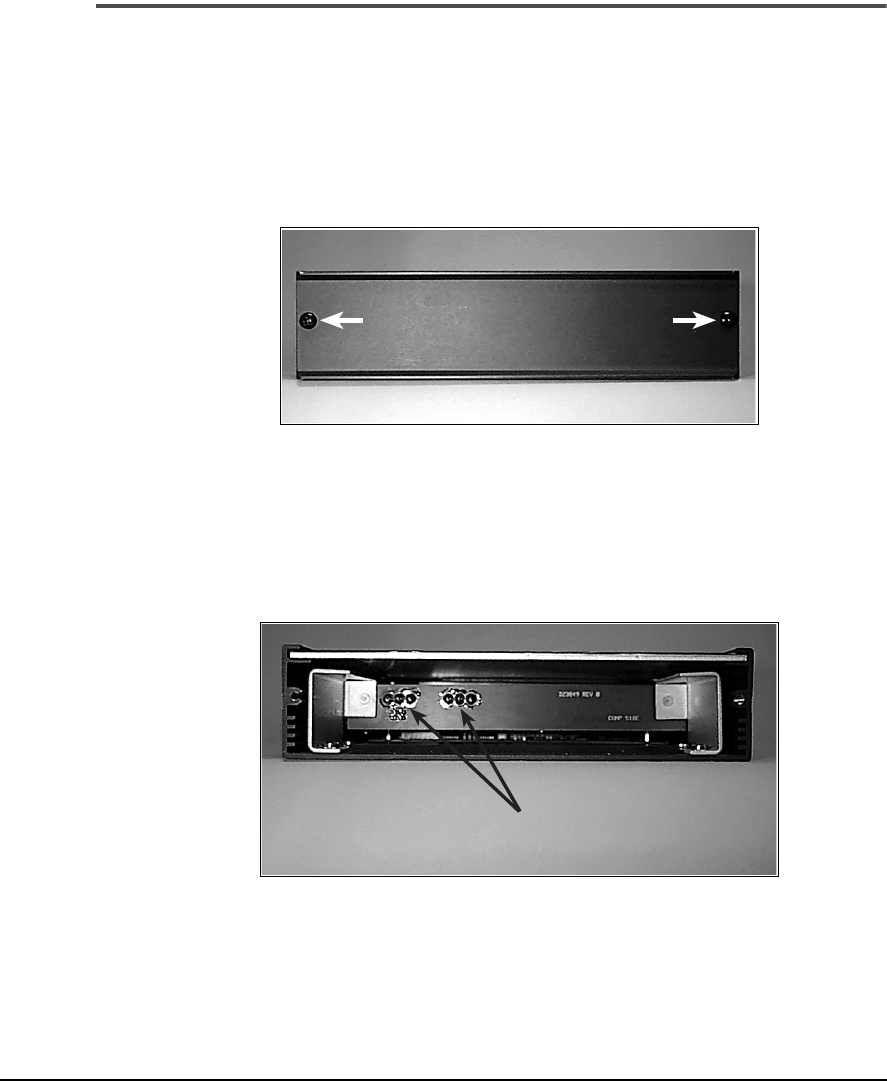
9-10 System Maintenance and Troubleshooting
Changing the UltraSpec 8117 Analyzer Battery
To change the UltraSpec 8117 analyzer’s battery pack:
1·····Make sure that the analyzer is Off, and that the battery charger power
supply is
not
connected to the analyzer.
2·····On the bottom of the analyzer, remove the two screws on the bottom
panel as shown below. Then remove the panel.
2
3·····Using the tabs on the sides of the battery pack, carefully remove the
battery pack from the battery compartment.
4·····Insert the new battery pack into the analyzer case, ensuring that the
strip contacts on the battery pack line up with the connection pins
inside the battery compartment.
3
battery pins
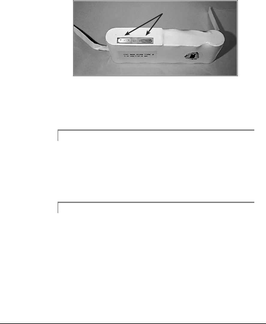
9-11
UltraSpec Analyzer Battery Maintenance
4
5···· Tuck the battery pack tabs into the case on the sides of the battery pack.
Make sure that the tabs do not interfere with the installation of the
bottom panel.
6···· Replace the bottom panel and screws.
Caution!
Do not change the battery pack with the battery charger connected as
damage may occur to the analyzer.
See “Using the Model 8211 and Model 8212 Battery Chargers” on page
9-14 for information about recharging batteries using the 8211 battery
charger.
Note
Optional accessories that provide alternative charging
methods are available for the UltraSpec analyzer, see “Acces-
sories and Optional Products” in the Appendices.
strip contacts

9-12 System Maintenance and Troubleshooting
8215/8225 Fixtures General Maintenance
Care and Handling
To ensure satisfactory service from this system, follow these procedures:
• Keep the mounting base and chain mounting posts lightly oiled to
prevent them from corroding.
• To maintain repeatability and accuracy, avoid dropping fixture
items. Refer to the Customer Assistance section for repair, update,
and calibration.
• Do not subject system items to large temperature swings.
• Do not engrave on the sensor heads.
• Keep all lens free of grease, dirt, oil, and other smudges.
• Clean the laser and target lens with a soft, lint-free cloth and standard
lens cleaning solution (a field size cleaner container is available from
CSI). Never use an organic solvent such as a thinner or benzine.
• Store laser heads in the carrying case when not in use.
Calibration
The Model 8215/8225 calibration should be checked every two years.
Return the sensor heads to CSI for a calibration check. All calibrations are
NIST traceable.

9-13
Conditions That can Cause Problems With the 8215/8225
Conditions That can Cause Problems With the 8215/8225
Water vapor or dust can interfere with a target “seeing” its laser. The air
between the sensor heads should be visually clear. Take care to ensure that
the air between the laser heads is not being heated from steam leaks, unin-
sulated piping, etc. Heated air rising within the span between the sensor
heads can refract the laser beams and cause errors in the alignment read-
ings.
Operate the 8215/8225 fixtures at ambient temperatures. If the fixtures
have been stored at a different temperature than the ambient temperature,
allow the 8215/8225 fixtures to reach ambient temperature. Ensure that any
heat source that may be present is not creating a large temperature differ-
ence between the 8215/8225 fixtures and the ambient temperature. Sun-
light itself will not cause a laser reading problem.
Conditions such as building construction materials and contents, other
radio systems operation in the vicinity at or near the same operation fre-
quency, and noise generated by nearby equipment may make RF commu-
nication unsatisfactory. If this problem occurs, use direct cable
communications.

9-14 System Maintenance and Troubleshooting
Using the Model 8211 and Model 8212 Battery Chargers
Battery Charging
Batteries may be charged with the Model 8211 or the Model 8212. The
Model 8211 is a “smart, drop-in” charger that can provide a fast- or trickle-
charge for the laser heads and analyzer. In fact, it can discharge the laser
heads, if necessary. The Model 8212 is an “overnight” trickle-charger that
can only trickle-charge laser heads and the analyzer.
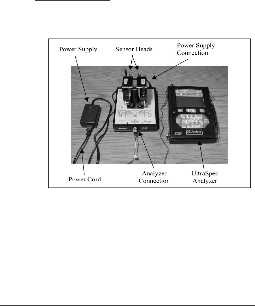
9-15
Using the Model 8211 and Model 8212 Battery Chargers
Model 8211 Smart Charger
The Model 8211 provides all battery charging needs and comes with the
system. It is a “smart, drop in” charger for the laser heads; it will also charge
the analyzer when plugged into a cable. The following picture shows both
of the laser heads
and
the UltraSpec analyzer being charged.
Charging the Sensor Heads and Analyzer with Model 8211 Charger
To set up the 8211, complete these steps:
1.····Plug the power cord into the power supply.
2. ···Plug the power cord into an AC receptacle.
3. ···Plug the power supply into the 8211 in the top end cap.
At that time, the beeper will sound indicating that power has been applied
to the battery charger. As a test, all LEDs will illuminate for 1.5 seconds.
4. ···Plug the analyzer charging cable into the bottom end cap.
The sensor heads and analyzer can now be charged either individually or,
all at the same time.

9-16 System Maintenance and Troubleshooting
Charging the Sensor Heads with the Model 8211
Place the sensor heads over the posts so that the heads face outward as
shown in “Charging the Sensor Heads and Analyzer with Model 8211
Charger” on page 9-15. Heads can be charged individually or together.
For maximum safety, the battery charger has a “Pending” status LED,
which lights momentarily when the head is first placed on the charger. If a
battery is very low, or is out of a specific temperature range, it cannot be
safely charged. When this condition occurs the “Pending” indicator
remains light. While “Pending,” the charger is actually charging the bat-
teries at a very low rate. This brings the low battery into acceptable voltage
range. Once the battery temperature and voltage are suitable for charging,
the charger automatically begins trickle charging and the “Trickle” indi-
cator light turns on.
To fast charge or discharge the battery the “Fast” button or “Discharge”
button must be pressed. If the “Fast” button or “Discharge” button is
pressed while the battery voltage is too low or temperature is not suitable
for “Fast” or “Discharge” operation, the indicator light will flash on and off.
This response acknowledges the request but indicates that the charger
cannot follow the request at that time. Once voltage and temperature con-
ditions are suitable, the requested “Fast” or “Discharge” operation will
begin and the indicator light will change to a steady light.
Indicator Light Charging Status
Pending Waiting for safe voltage and
temperature
Discharge (steady) Batteries discharging
Discharge (flashing Discharge requested, waiting
for safe voltage or temperature
Fast (steady) Batteries in fast charge
Fast (flashing) Fast charge requested, waiting
for safe voltage or temperature
Trickle Batteries in trickle charge,
topping-off, or charge complete

9-17
Using the Model 8211 and Model 8212 Battery Chargers
Warning!
Note that if the battery is fully charged, a user is able to
initiate fast charge by pressing the “Fast” button. After
about 2 minutes, the charger will stop fast charge in this
case. However, to avoid overcharging batteries, you
should not press the “Fast” button with an already fully
charged battery.
After the “Fast” charging cycle has completed the charger beeper will
sound and automatically begin trickle charging. When this condition
begins the “Trickle” indicator light turns on indicating that the battery is
almost completely charged or is completely charged. For the laser head bat-
teries, the two conditions occur within a few minutes of each other. Charge
time from a fully discharged set of batteries to approximately a 90% voltage
charge is 15 minutes.
After the “Discharge” cycle has completed the charger automatically begins
fast charging and the “Fast” indicator light turns on. To avoid the battery
memory concern, use the “Discharge” mode when you have more than 20
minutes to charge the sensor head batteries. The typical charge cycle is as
follows:
Action Time
Press DISCHARGE button Start
DISCHARGE complete, FAST starts 7 minutes
FAST complete, TRICKLE starts – charging complete 22 minutes
NOTE:
The heads can be left on TRICKLE indefinitely (until the next time they are
needed).

9-18 System Maintenance and Troubleshooting
Note
After power has been applied to the charger and the sensor
head have been placed in it, if none of the LED's for that sensor
head are lit then the contact between the sensor head and
charger may not be sufficient enough to charge the batteries.
No LED's lit indicates a “no battery present” state. If this
occurs, remove the sensor head from the charger and try
reseating it back into the charger.
Note
After a charging cycle has begun, if that charging cycle is inter-
rupted (e.g. disconnecting the power to the charger or
removing the sensor head from the charger) the charging pro-
cess described above begins again from the beginning. There-
fore, if the charger cycle is interrupted while the “Fast” charge
mode is in progress then the charger will then automatically
begin trickle charging after “Pending.”
“Pending LED” will light momentarily and switch into FAST charge.
Charge time for a fully discharged set of batteries is 15 minutes. The beeper
will sound when both heads are charged (90%) and have switched to
TRICKLE charge. To avoid the NiCad battery memory concern, use the
DISCHARGE mode when you have more than 20 minutes to charge the
sensor head batteries.

9-19
Using the Model 8211 and Model 8212 Battery Chargers
Charging the UltraSpec 8000 Analyzer with the Model 8211
Plug the charging cable (A821101) from the bottom end cap on the 8211
(earlier than Rev. 4) into the top of the analyzer. TRICKLE mode will start
the charge cycle. To change to FAST mode, press the FAST button in the
Analyzer section. The analyzer battery is not monitored but utilizes a timer
to avoid overcharging. The 8211 will charge the analyzer in FAST mode for
15 hours or until the FAST button is pressed again (whichever comes first).
If the 8211 charger is Rev. 4 or later, it cannot be used to charge an
UltraSpec 8000 analyzer.
Charging the Model 8117 Analyzer with the Model 8211 Charger
Plug the charging cable (A821102) from the bottom end cap on the 8211
into the charger port on the top end cap of the 8117 analyzer. The battery
pack will recharge in 14 to 16 hours. If the batteries are continually allowed
to remain on charge for longer than 16 hours, battery degradation will
occur. Overnight charging is allowable, however, charging over a weekend
is not recommended.
Charging the Model 2120 Analyzer with the Model 8211 Charger
Plug the charging cable (A821102) from the bottom end cap on the 8211
into the charger port on the top end cap of the 2120 analyzer. The battery
pack will recharge in two and one half hours. After the battery pack has
been fully charged, the battery charger will automatically switch to a trickle
charge.
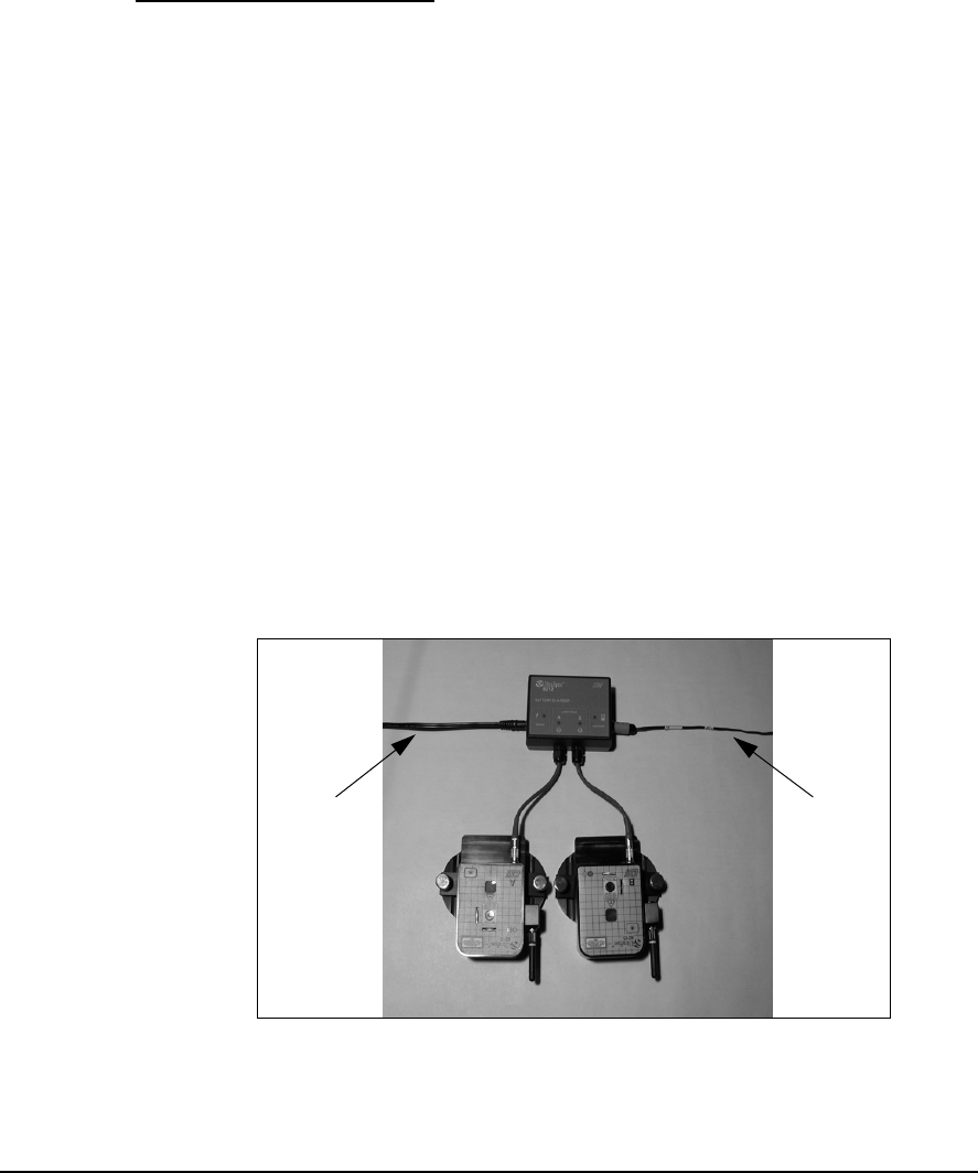
9-20 System Maintenance and Troubleshooting
Model 8212 Trickle Charger
The Model 8212 battery charger is a trickle charger for the laser heads and
the Model 8117 UltraSpec analyzer. It will charge the laser heads and ana-
lyzer in ten hours. This is intended to be an overnight charge. The laser
heads should not be left on charge over 24 hours. Continual overcharging
the batteries will result in a shortened life.
To set up the Model 8212 charger, complete the following steps:
1. ··· Plug the power cord into the power supply that came with the 8117 or
2120 analyzer.
2.··· Plug the power cord into an AC receptacle.
3.··· Plug the power supply into the Power connection on the 8212. Ensure
the associated LED illuminates.
4.··· Plug the laser heads into the A and B pigtails from the 8212. Ensure
the associated LEDs illuminate.
5.··· To charge the analyzer, plug the 821102 charge cable into the
analyzer connector on the 8212. Ensure the associated LED on the
8212 illuminates.
See the photo below that illustrates the 8212 setup with a pair of laser heads
and a Model 8117 UltraSpec analyzer.
Charging the Model 8215 Laser Heads with the Model 8212 Charger
From
Power
Supply
To 8117
Analyzer

9-21
Using the Model 8211 and Model 8212 Battery Chargers
Charging the Model 8117 and 2120 Analyzers with the Model 8212 Charger
After plugging the charging cable (A821102) into the 8212, plug the other
end of the cable into the charger connection on the top end cap of the
Model 8117 or the Model 2120 analyzer. Ensure the LED on the analyzer
illuminates, if applicable. The Model 8117 battery pack will recharge in 14
to 16 hours. If the batteries are allowed to continually remain on charge for
longer than 16 hours, battery degradation will occur. Overnight charging is
allowable, however, charging over a weekend is not recommended. The
Model 2120 battery pack will recharge in two hours then switch to a trickle
charge that will not damage the battery.
Charging the Model 8000 Analyzer with the Model 8212 Charger
The Model 8212 trickle charger CAN NOT charge an UltraSpec 8000 ana-
lyzer. To charge the 8000 use either a Model 8211 (previously discussed in
this section) or the Model 2115-C-120 wall charger.
Note
See “UltraSpec 8000 Analyzer Battery Recharge” on page 9-6
and “UltraSpec 8117 Analyzer Battery Recharge” on page 9-9
for information on optional methods of charging the UltraSpec
analyzer.
Battery Usage - Laser Heads
A rechargeable battery pack is used to power each sensor head. A fully
charged battery pack will give 3 to 4 hours of continuous service while
transmitting data. Longer operation is possible since typical alignments do
not require continuous communication with the analyzer. The battery is
designed to have a long life and is not intended to be replaced by the user.
Replacement should be performed only at CSI. CSI recommends that the
batteries be replaced after 1,000 charges/discharges.

9-22 System Maintenance and Troubleshooting
To conserve battery life, the 8215/8225 has a sleep mode and a shutdown
mode. The sleep mode is activated after 5 minutes of no communication
with the analyzer. In the sleep mode, the laser beam and RF communica-
tion are shutdown until communication is reestablished. All data in
memory is saved. In the auto-shutdown mode, the sensor heads are com-
pletely shutdown. The Power button will start the sensor heads again. All
data in memory is lost, therefore another sweep should be taken.
The sleep and auto-shutdown modes can be disabled. When turning the
sensor heads on, press and hold down the Power button (the LEDs will turn
on when the Power buttons are first pressed). The LEDs will turn off when
the sleep mode is disabled (approximately 3 seconds). When both LEDs
light again, the shutdown mode will be disabled (approximately 5 seconds).
Refer to “Laser Head Status Screen” on page 3-8 for more information.
Note
Please note that this disables the battery conservation (for the
sensor heads) therefore, if the heads are left on, the batteries
will run down.