Computational Systems orporated 8000RF Laser Alignment Fixture User Manual Appendix A
Computational Systems Incorporated Laser Alignment Fixture Appendix A
Contents
Appendix
Appendix
A-1
A
Foot Pre-Check Types
Foot Pre-Check Measurement Methods – Soft Foot and Frame Distortion
Index (FDI)
Soft foot is a condition where all feet (typically four) of a machine compo-
nent (such as a motor or gearbox) will not rest on the same plane. This con-
dition also exists if the machine baseplate pads (where the machine foot
rests) are not on that same plane. If this condition continues to exist and is
not corrected, two problems will occur.
First, it will be very difficult to align the machine. You will appear to be
“going in circles” trying to move the machine into alignment. Second, but
most important, the machine will not operate properly. The component
was not designed to operate in a bound condition. When this happens,
binding will occur causing stress at the bearings and changing the operating
clearances (inside the component). To prevent binding, you must check all
the feet,
even those on the machine not being moved
.
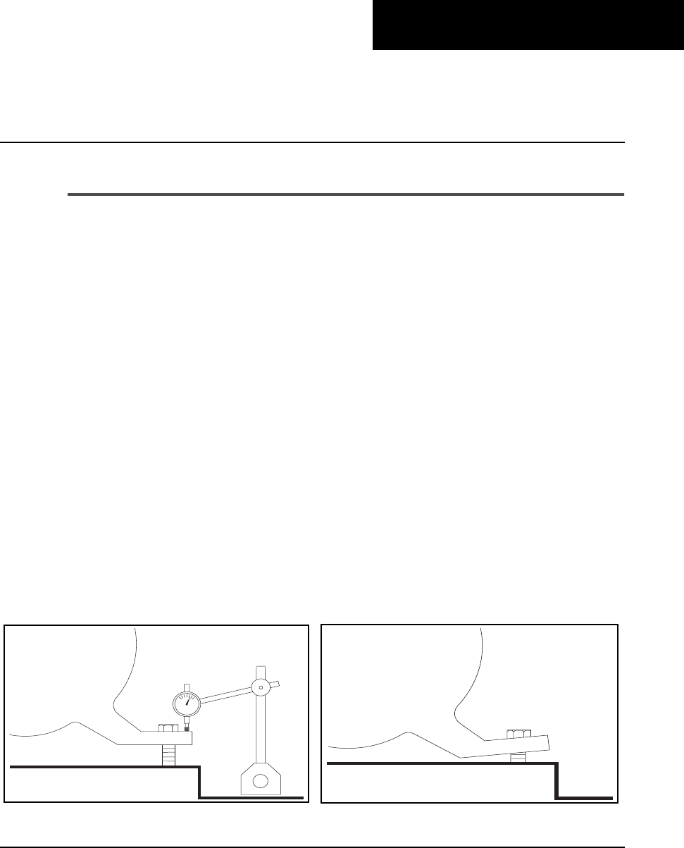
Traditional methods of measuring soft foot conditions included mounting a
dial indicator at the machine foot (similar to Fig 1). The hold-down bolt was
then loosened while the indicator was watched for movement. If the indi-
cator moved more than a predetermined amount (usually 0.003 inch), the
foot required correction. A shim equal to the amount of the indicator move-
ment was then shoved under the foot.
Fig 1 Fig 2
A-2 Foot Pre-Check Types
This method assumed that a parallel soft foot existed. However, a large per-
centage of problem feet are
angular soft feet
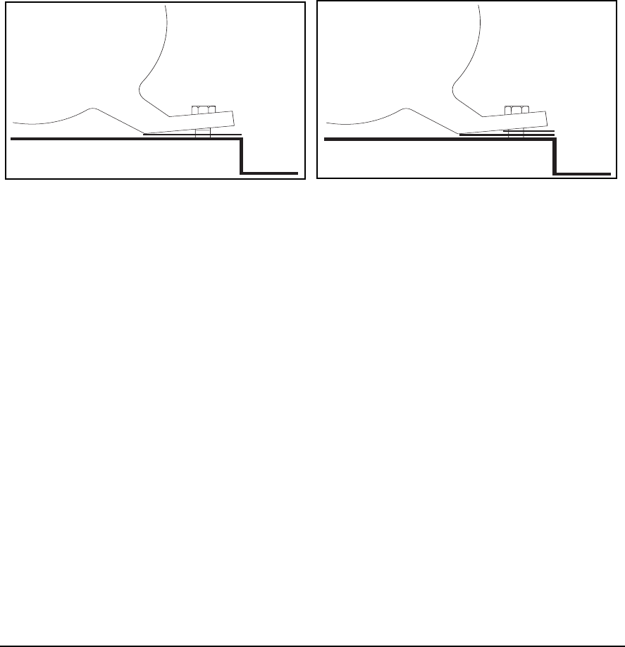
(similar to Fig 2). Correcting this
type of problem with a full shim can make the condition worse
(see Fig 3). Correction should be determined with a set of thickness gauges
(feeler gauges). The result is usually a wedge shim similar to Fig 4.
The laser alignment system allows you to locate the problem feet and
bypass those feet that are OK. While the hold-down bolts are individually
loosened and retightened, the laser system will measure the shaft to shaft
position. This actually measures how much each connection affects shaft
alignment. In a perfect condition, loosening bolts should not move the
shafts at all.
Two different laser methods are available to evaluate the measured move-
ment at the shafts. They are:
• Soft Foot
• Frame Distortion Index (FDI)
Although they evaluate the data differently, both methods give you a sense
of soft foot severity at each location. Soft Foot results are shown by the
number of X’s displayed and FDI results are shown as a numerical value.
Fig 3 Fig 4

A-3
Soft Foot Evaluation
The Soft Foot evaluation provides you with a sense of severity without
showing numbers. Numbers are not used because,
most of the time, they are
mistaken for the value of the shims
(totally wrong). When the numbers are cal-
culated, they are compared against the tolerance (usually 0.5 mils/inch). If
a particular foot is below the tolerance, it is labeled OK. If the number is
between one and two times the tolerance, it is labeled with a single X. If the
number is between two and three times the tolerance, it is labeled as XX.
If the number is greater than three times the tolerance, it is labeled as XXX
(the more X’s, the greater the severity).
The tolerance can be changed in
UltraMgr and downloaded to the analyzer
.
The number is evaluated by taking the horizontal and vertical movement
on each target and calculating the total movement on each target. The
largest movement of the two is then divided by the distance between the
heads (dimension C) to determine the angle of deflection caused by loos-
ening a hold-down bolt. This angle is compared to the tolerance for final
evaluation for that foot.
The advantage of this method is that it uses a combination of horizontal and
vertical movements on the target to determine the problem feet. Experi-
ence has shown that approximately 20% of the soft foot conditions cause a
horizontal move
because of a severely bent foot
.
FDI Evaluation
The Frame Distortion Index provides you with a sense of severity
with
numbers
.
Caution!
Do not mistake these numbers for shim values.
When the numbers are calculated, they are compared against the tolerance
(
usually
excellent <2 mils and acceptable <3 mils). If a particular foot is in
the excellent range, the number is plain. If the foot is acceptable, it will have
a clear box around the number. If the foot is out-of-tolerance, it will have a
solid box around the number. The higher the number, the greater the
severity.
The tolerance values can be changed in UltraMgr and downloaded to the
analyzer
.

A-4 Foot Pre-Check Types
The number is evaluated by measuring the vertical angle and applying it to
an old millwright’s “rule of thumb”. It is:
FDI = 2 x Vertical Angle x Inboard to Outboard Foot Distance
Vertical angle is measured at the shafts when the hold-down bolts are loos-
ened and the Inboard to Outboard Distance is the distance from the front
to the back feet of the component being measured (dimensions A or E in
the Machine Dimensions screen). This value is compared to the tolerance
for final evaluation for that foot.
The disadvantage of this method is that it uses only vertical movement to
determine the problem feet (and the numbers are commonly mistaken for
shim correction values). However,
this is the only method currently used by
Prüftechnic alignment products
.

Appendix
B-1
B
Pinouts and Wiring Diagrams
RS232 D Connector Pinouts
Pin Description
01 Ground (connected to 7, 16, 22)
02 Transmit (RS-232)
03 Receive (RS-232)
04 Connected to 05
05 Connected to 04
06 Connected to 08 and 20
07 Ground (connected to 1, 16, 22)
08 Connected to 06 and 20
09 <Reserved>
10 <Reserved>
11 Transmit (for CSI Modem only)
12 Receive (for CSI Modem only)
13 +5.0 Volts
14 Sensor Button
15 CTS (for CSI Modem)
16 Ground (connected to 1, 7, 22)
17 <Reserved>
18 +9.5 Volts
19 <Reserved>
20 Connected to 06 and 08
21 +10 Volts — Accelerometer Signal Input
22 Ground (connected to 1, 7, 16)
23 Volts In (Signal Input)
24 -10 Volts — Accelerometer
25 <Reserved>
B-2 Pinouts and Wiring Diagrams
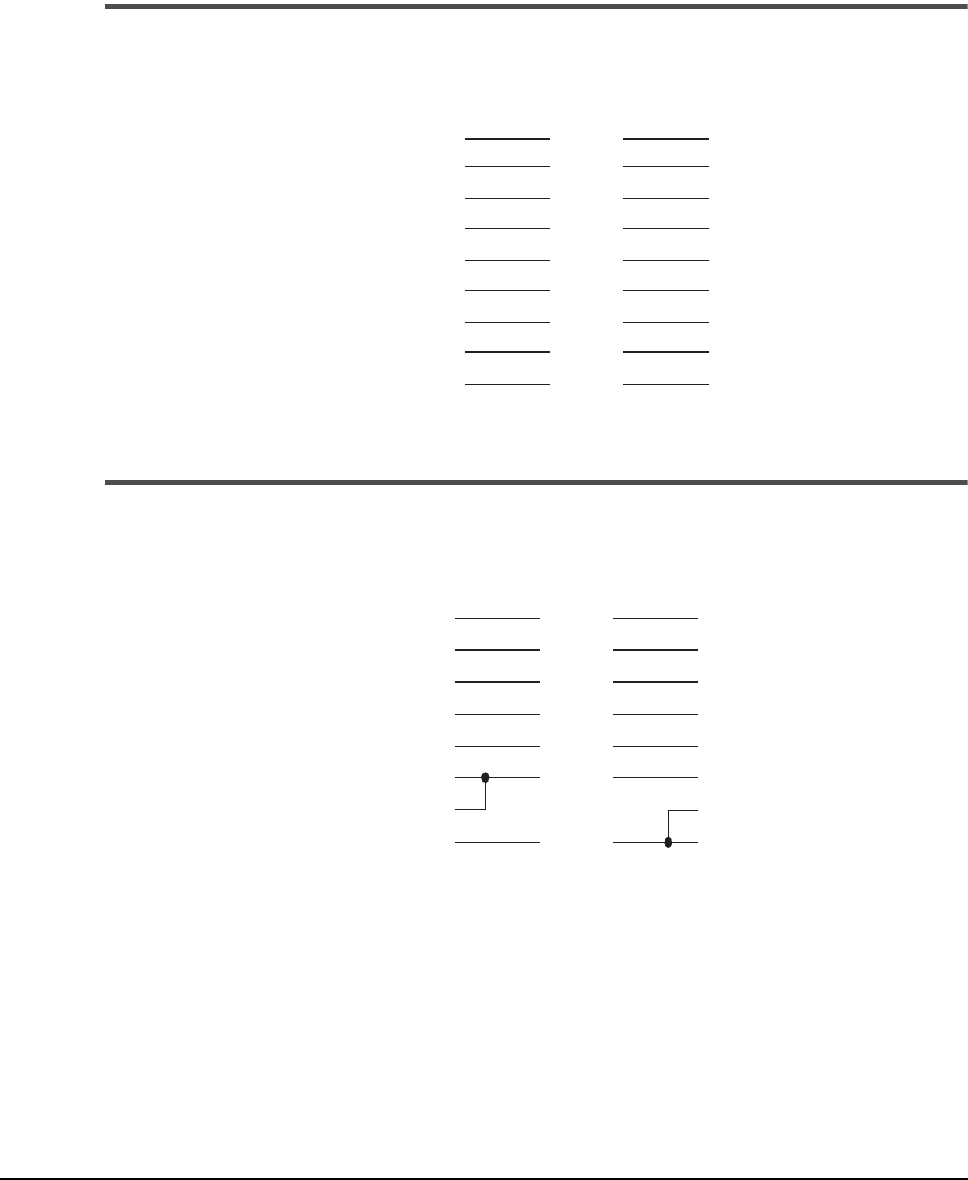
Model 635 Modem Cable
1
Model 639 Communications Cable
2
3
1
2
3
4
5
6
7
8
20
1
2
3
4
5
6
7
8
20
Black
Brown
Red
Orange
Yellow
Blue
Green
Violet
White
to UltraSpec Analyzer to Modem
2
3
4
5
7
6
8
20
2
3
8
7
5
4
6
1
Brown
Red
Orange
Yellow
Green
Blue
Violet
to UltraSpec Analyzer to Computer

Appendix
C-1
C
Technical Specifications
UltraSpec 8215/8225 Laser Alignment Fixtures Specifications
Specification Description
Laser Diode In-Ga-Al-P, Class II (CDRH) / Class2 (IEC), Visible
Wavelength 670 nm (typical)
Output power Pulsed, <1.0 mW (average)
Laser Safety Class Class II (CDRH) / Class2 (IEC)
FDA 21CFR 1040.10 and 1040.11
Beam Divergence
≤
225 µrad (8215),
≤
30 µrad (8225),
Target Size 8215: 10 mm by 10 mm (0.394 inches by 0.394 inches)
8225: 20 mm by 20 mm (0.787 inches by 0.787 inches)
Target Range (typical) 8215: 9 mm by 9 mm (0.354 inches by 0.354 inches)
8225: 18 mm by 18 mm (0.709 inches by 0.709 inches)
Resolution 0.0000394 inches / 0.001 mm
Linearity Better than 1.5%
Environment Protected from ambient light interference
Laser housing Aluminum
Inclinometer Internal, fully automatic
Inclinometer resolution Better than 1°
Measurement axes 6 total, 2 displacement and 1 rotational axis per laser
head
Operating temperature 0° to 115° F (-17.8° C to 45° C)
Storage temperature 0° to 140° F (-17.8° C to 60° C)°

C-2 Technical Specifications
UltraSpec 8215/8225 Laser Alignment Fixtures Specifications (continued)
Specification Description
Humidity 10 to 95%, non-condensing
Power management Auto “sleep” and “power down” modes
Battery Nickel cadmium
RF Operating Frequency 916.5 MHz
RF Operating Range 0 - 50 ft (0 - 15 m), typical
Battery life 3 - 4 hours continuous operation – 8 hours typical
1
Battery charging station Fully automatic super fast smart charger
(auto-switching, 110-240 VAC, 50/60 Hz)
Battery charging time 15 minutes (zero to full charge)
Laser to analyzer
communication
Cableless RF and/or direct cable connection
Minimum separation Any positive separation (faces not touching)
Maximum separation 8215: 30 ft (9 m), 8225: 100 ft. (30.5 m)
Standard mounting
bracket
2
Carbon steel base – thickness 0.75 in (19 mm)
Minimum shaft diameter
with standard bracket
0.625 in (16mm)
Maximum shaft diameter
with standard bracket
2
26 in (660 mm) – requires chain extension for shaft
diameters above 8 in (200 mm)
Vertical clearance with
standard brackets
2
5.25 in (152 mm)
Calibration Calibration to NIST traceable standards
Weight of total system 33 lbs (15 kg) – includes laser heads, brackets, analyzer
and accessories
1
Based on 25% laser operation, 25% sleep mode, and 50% analyzer only
2
Other brackets are available for special applications

C-3
UltraSpec Analyzer General Specifications
UltraSpec Analyzer General Specifications
Physical Dimensions
Height: 27 cm (10.5 inches)
Width: 17 cm (6.8 inches)
Depth: 4 cm (1.8 inches)
Weight: 2.5 kg (5.0 pounds)
Environmental Limits
Temperature: -10° to 50° C (15° to 120° F)
Relative Humidity: 0 to 95% non-condensing
Enclosure
UltraSpec 8000 analyzer: Extruded aluminum case housed in a leather case
with a clear vinyl front and flip stand.
UltraSpec 8117 analyzer: Extruded aluminum case housed in a leather case
and a wrap-around clear vinyl sheath. (No flip stand.)
Power Supply
Battery:
Model 8000 rechargeable, ±12 V battery pack
Model 8117 rechargeable, ±7.2 V battery pack
Capacity: 1.2 amp-hours
Recharge time: 14 to 16 hours (fast charge)
Operation time: Model 8000 10 hours of normal usage on a full charge
Model 8117: 8 hours of normal usage on a full charge

C-4 Technical Specifications
Note
To prevent loss of memory, install a new battery within four
hours after removing the old battery. An optional recharging
adapter is available which will permit charging a spare battery
pack external to the analyzer.
LCD Display
Viewable area: 7 x 13 cm (2.75 x 5.0 inches)
Dot resolution: 128 vertical x 256 horizontal pixels
Alphanumeric text: 8 lines x 42 characters
The text and graphic displays use “super-twist” liquid crystal technology.
This technology provides a super-sharp dark screen image that you can see
more easily in conditions of low ambient lighting. Electroluminescent back-
lighting also enhances visibility.

C-5
UltraSpec Analyzer Input Specifications
UltraSpec Analyzer Input Specifications
Input Signal Types
A two milliamp ICP type power supply inside the instrument powers sen-
sors such as accelerometers. This power supply provides a 2 milliamp con-
stant current at 20 volts nominal. ICP power may be used or bypassed
depending upon type of input selected.
• ICP Used: + 9 volts
• ICP Bypassed: + 21 volts
• Input Impedance: greater than 150 k ohms
• A/D Converter: 12 bits accuracy
• Dynamic Range: 70 dB or greater
Note
Full scale vibration level depends on the type of sensor used
and its sensitivity. Full scale vibration level is ± 90 g’s when
using an accelerometer with a sensitivity of 100 mV/g.
Autoranging
The UltraSpec analyzer automatically scans the input signal for each mea-
surement. It sets the input range to maximize the dynamic resolution while
maintaining the dynamic range of the A/D converter at 72 dB. Full-scale
ranges from 21V to 8 mV are supported. The noise floor is typically less
than 3 microvolts for a 400-line spectra taken using a 1000 Hz maximum
frequency.
Input Sensor Types
(ProAlign Plus Only)
Portable sensors: Laser sensor heads (Model 8215/Model 8225)

C-6 Technical Specifications
Communications
The UltraSpec analyzer can be downloaded from standard IBM PC/XT,
PC/AT, or fully compatible computers that have an RS232 serial link. Baud
rates may be selected up to 76.8K. Remote links via modem are fully sup-
ported.

C-7
Measurement Specifications
Measurement Specifications
Data Storage Capacity
Standard memory: 1.0 Mbytes
Maximum number of stored jobs: 100 (Alignment only)
Ranges
(Alignment Only)
Maximum PSD input for 8215: ± 170 mils (±4.318 mm); for 8225: ± 340
mils (±8.636 mm)
Maximum thermal growth input: ± 250 mils (± 6.35 mm)
Resolution
(Alignment Only)
Manual Input: 0.1 mil (.002 mm)
Display: 0.1 mil (0.002 mm)
Machine move: 1.0 mil (.025 mm)
Notes
Total predefined/user defined notes available: 99
Maximum number of notes/job: 40
Reading Sets
(Alignment Only)
Maximum number of reading sets per job: 20
Baud Rates
300, 1200, 2400, 4800, 9600, 19.2k, 38.4k, or 76.8k

C-8 Technical Specifications
RF Operating Frequency (Alignment Only)
916.5 MHz
Data Collection
(ProAlign Plus Only)
Method Mode
CSI Laser
Auto Sweep
4 Point Auto
Manual Sweep
4 Point Manual
Straightness
Dual Pass

Appendix
D-1
D
Accessories and Optional Products
Optional Items for Laser System
Part No. Description
D22773 .................Mounting Chain extension, 2 ft (660 mm), standard mounting base
800002.................. with one straight and one rigid angle Lemo connectors
800003.................. with straight Lemo connectors
8AA50..................Magnetic straightness fixtures (see 800056)
800052.................. Non-rotational (Soft Mount) alignment fixtures
8AA54..................Thin mounting brackets, 5/8 inch - 4 1/2 inches (15 - 115 mm) diameter
8AA55..................Thin mounting brackets, 3/4 inch - 20 inches (19 - 510 mm) diameter
800056.................. Magnetic coupling fixtures
Other Accessories
Part No. Description
8JB050.................. Portable horizontal jackbolts kit; motor sizes 2 to 300 HP
8JB100..................Portable horizontal jackbolts kit; motor sizes 300 HP+
8JB200.................. Portable horizontal jackbolts kit; motor sizes 2 to 300 HP+
See Price List .......Precut stainless steel shims
Recommended Spare Parts*
Part No. Description
D22745.................Chain Clip
8AA10 .................. CSI Tape Measure, 6 ft (2 m)
800001..................8210 Direct Connect Cable
821510................... 8215/8225 Direct Connect Cable
8215C2-PM..........8215/8225 Dual Pass Cable
* Other spare parts are available upon request.

D-2 Accessories and Optional Products
Analyzer Travel/Carrying Cases
Part No. Description
801 ........................Accessory pouch (leather; worn on belt)
D22735.................Leather case for UltraSpec 8000 analyzer
D24312 .................Leather Case for UltraSpec 8117 analyzer
812.........................Breakaway shoulder strap for UltraSpec 8117 analyzer
D24492.................Hard shell case (locking) for UltraSpec analyzer and laser fixtures
D24266.................Leather case for UltraSpec 8117 analyzer
D10690.................Clear vinyl sheath for UltraSpec 8117 analyzer
Analyzer Accessories
Part No. Description
705 ........................2400-baud modem (DB25(F) to Tele(F))
705-1.....................Model 705 AC adapter, input 220VAC @ 50 Hz, output 9VDC @ 200 mA
720A .....................Analyzer printer interface (DB25(M) to DB25(F))
8003......................3-Way Splitter (DB25(F) and DB25(F) to DB25(M))
D24129.................UltraSpec 8117 Icon Front Panel Legend Card
Temperature Sensors
Part No. Description
505........................Infrared temperature sensor with 615-C cable (displays in Fahrenheit)
505-C....................Infrared temperature sensor with 615-C cable (displays in Celsius)
515.........................Laser temperature probe

D-3
Batteries/Analyzer Chargers
Part No. Description
A2115-C-120........ UltraSpec 8000 analyzer spare battery charger, 120V, 60 or 120 mA
A108-12-3............. UltraSpec 8000 analyzer battery pack, 1200 mA hr, 3-pin
660-3..................... Charge adapters for Model 105-3, 105A-3, 108-3 battery pack to charger
connector (3-pin)
660-5..................... Charge adapters for Model 105-5, 108-5 battery pack to charger connector
(5-pin)
8211 ...................... Laser head and UltraSpec analyzer battery charger
93140 .................... UltraSpec 8117 analyzer battery charger, 120V
8212 ...................... 8210 Sensor head and UltraSpec analyzer trickle charger
Note
To fast charge the battery outside the analyzer, a 660-3 or
660-5 charger adapter is required.

D-4 Accessories and Optional Products
Cables and Adapters
Part No. Description Input Output
639 ............. Analyzer to computer communications cable DB9 (M) DB25 (M)
634............... Computer to modem cable DB25 (F) DB25 (M)
635..............Analyzer to modem cable DB25 (M) DB25 (M)
650............... Union connector BNC (F) BNC (F)
652............... BNC Tee BNC (F) 2 ea. BNC(M)
654............... BNC 50
Ω
terminator BNC (F) –
661............... General, 4' cable (RG59) 75
Ω
BNC (M) BNC (M)
662............... Hi-temperature, 4' cable (RG142) 50
Ω
BNC (M) BNC (M)
665............... Accel., 10' cable (RG174) Microdot (M)BNC (M)
8000IQ........Infrared transceiver for analyzer to 8210 DB25 (M) Infrared
communication
80000RF..... Radio Frequency (RF) interface for analyzer DB25 (M) RF
communication
800001 ........ 8210 Direct connection adapter at Analyzer DB25 (M) LEMO (M)-2
821510 ........8215/8225 Direct Connection adapter DB25 (M) LEMO (M)-2
at analyzer
800002 ........ Direct connection cable interface LEMO (F) LEMO (M)
(right angle)
800003 ........Direct connection cable interface LEMO (F) LEMO (M)
at analyzer
8215C2-PM
...8215/8225 Dual Pass Direct Connection LEMO (M) LEMO (M)
cable

D-5
Balancing
Part No. Description
8000-BK............... UltraSpec Balancing Accessory Kit, 4-channel
BK1 ...................... Balancing Accessory Kit
Alignment
Part No. Description
8210 ...................... IR Laser Alignment Fixtures with 10 mm by 10 mm PSD’s
8215 ......................RF Laser Alignment Fixtures with 10 mm by 10 mm PSD’s
8225......................RF Laser Alignment Fixtures with 20 mm by 20 mm PSD’s

D-6 Accessories and Optional Products
Customer Support
CSI takes great pride in our customers and is committed to providing the
highest standard of customer support. Our number one priority is to pro-
vide prompt and efficient service to all of our customers. To contact our
Customer Support department, please call (865) 671-4274 (4CSI). To reach
the Sales Support department, dial (865) 675-2110 and ask our receptionists
to direct your call.
To extend the level of support to CSI customers, we have an electronic mail
system which is connected through the Internet directly to the Customer
Support group. The address is:
custserv@compsys.com
Customer Support also has a Web page on the Internet. You can access it
by visiting our
corporate
Web page at:
http://www.CSImeansReliability.com
Once there, choose the Customer Support option and a set of frames will
be displayed with general information about CSI Customer Support. There
are links to specific information such as TechNotes, MasterService Warran-
ties, and Maintenance Quotes. Also, the following prompt provides a link
to the Customer Support Web page.
Visit our Customer Service
Site for additional Customer
Support information.
Click on this option to access
additional
technical information and assis-
tance for CSI products.

D-7
Customer Support
DoctorKnow™
The DoctorKnow system was originally developed to provide a means of
transferring high volume, ever-changing technical information to support
personnel at CSI. Because it was so successful, further enhancements were
made so that it could also be provided to CSI customers. It
now
provides:
• A mechanism to FAX information to the customer (while on-line)
and
• Direct access to the Customer Support Web page (through the
Internet – see previous section)
In the future
, Customer Support plans to include file transfer capabilities.
This will allow prompt evaluation of customer data and/or setups. We also
plan to provide software updates (for customers with maintenance agree-
ments) by using the Internet.
Reliability Services
CSI provides a broad range of in-plant services including startups, database
troubleshooting and diagnostics. Our Reliability Services Department con-
sists of qualified individuals with experience in a variety of technologies
and industries. For information, call (865) 675-2400, Ext 2358.

D-8 Accessories and Optional Products

G-1
Glossary
Accuracy
How close a measurement is to the absolute quantity being measured.
Alignment
Positioning two or more machines so that the rotational centerlines of their
shafts are co-linear under operating conditions.
Anchor Bolts (or Hold-down Bolts)
Bolts use to anchor or hold the machine to the base or foundation.
Angularity
The angle between two machine shaft centerlines; this angle is the same at
any point along either centerline. Normally specified in rise/run.
Axial Float (or End Float)
Movement of one shaft along its centerline due to the freedom of move-
ment permitted by a journal bearing or sleeve bearing. This adjustment
should be set before performing vertical and horizontal moves.
Backlash
Normally refers to the torsional play caused by the design or degraded con-
dition of a flexible coupling.
Baseplate
The surface (often made of steel plate or cast iron) to which the feet of a
machine are attached. The baseplate is normally mounted on a foundation
and grout.
Baud Rate
Unit of speed for data transmission over a serial communications link. The
UltraSpec analyzer supports rates from 300 to 76.8K baud.

G-2
Bolt Bound
The situation whereby the machine cannot be moved in the desired direc-
tion (either horizontally or vertically) because of mounting bolt restrictions,
or a limited number of shims.
Brackets (or Fixtures)
Components that mount to machine shafts or couplings to measure the rel-
ative position of the centerlines of two machines.
Coefficient of Thermal Expansion
The constant value or factor of expansion of a metal for a given increase in
temperature per length of the metal. This is different for each type of mate-
rial.
Cold Alignment (or Static Alignment, or Primary Alignment)
Condition in which machines are normally aligned. Changes in off-line to
on-line running conditions should be allowed for during this procedure so
that the machine will “grow” into alignment during operation.
Co-linear
Two or more lines positioned in space with no offset or angularity between
them.
Co-planar
Lying or acting in the same plane.
CPM
Cycles per minute. (Same as RPM.)
Current Job
Job in the UltraSpec analyzer that is currently active – the one that can be
easily modified.
Dodd Bars
A secondary alignment method.
Dutchman
A tapered filler ring for squaring cocked flanges, or a ring of uniform thick-
ness used to fill pipe gaps.

G-3
End Float
See axial float.
Essinger Bars
A secondary alignment method, or method to measure off-line to on-line
running condition change.
Face-rim Method (or Rim-face Method)
A method of shaft alignment measurement where the indicators are
mounted radially and axially on one machine or the other (not both).
Firmware
A term referring to the software that controls or instructs the function of the
UltraSpec analyzer.
Fixtures
See Brackets.
Foundation
The surface, often made of concrete, to which the machine baseplate is
mounted, often with grout between the baseplate and foundation to pro-
vide even support.
Frame Distortion Index
Method of measuring how much a Soft Foot condition will distort a
machine casting (casting distortion affects the alignment).
Frequency
Number of times an event repeats in a specific period of time.
Hertz
The measurement of frequency in cycles per second.
Hold-down Bolts
The bolts anchoring or holding the machine to the baseplate and founda-
tion.
Inclinometer
A device that indicates the rotational position of shafts.

G-4
Induced Soft Foot
A type of soft foot that is caused by external forces (coupling, pipe strain,
etc.) acting on a machine independent of the foot to baseplate connection.
In-phase
When applied to alignment brackets, the term means the Move and Fixed
brackets make the same angle with the horizon at each point of measure-
ment.
Jackscrew (or Jackbolt)
A bolt or screw attached to the base or foundation that is used to move or
position the machine (normally horizontally but sometimes vertically)
which is being moved.
Jackshaft
A long shaft used as a spacer between two machines.
Job
Usually identified with a number and description; represents data accumu-
lated during an individual alignment session.
Machinery Train
Three or more machines that must be aligned to one another.
Master
When used as a communications term, it is the unit that controls and deter-
mines when data will be transferred. In the UltraSpec system, the P/C is the
Master and the UltraSpec Analyzer is the Slave.
Micrometer, Outside
Tool used to measure the thickness of shims.
Milliradian
A unit (normally metric) used to describe the angle of one machine shaft
centerline to the other. It is the equivalent of mils/inch. It can also be
expressed as rise/run (1° = 17.45 milliradians).
Mils
A unit of measure for displacement (thousandths of an inch).

G-5
Mils/Inch
A unit (normally English) used to describe the angle of one shaft centerline
to the other. It is equivalent to milliradians. It can also be expressed as rise/
run (1° = 17.45 mils/inch).
Modem
A device that enables remote communications between the host computer
and the analyzer over telephone lines.
Notes
Specific observations that can be stored in each alignment job along with
the collected data. These observations can be predefined notes or user-
defined notes that have been created via the analyzer’s keypad, or a com-
bination of the two methods.
Off-line to On-line Running Condition
Movement of shaft centerlines associated with (or due to) a change in pres-
sures, temperatures and other forces between the static and operating con-
dition.
Offset
Distance between rotational centerlines at any given normal plane, usually
measured at the coupling midpoint.
Perpendicular
At right angles (90°) to a given line or plane.
Pipe Strain
Casing and shaft distortion caused by improper pipe flange fitup.
Predictive Maintenance
Technology of periodically monitoring the actual condition of machines to
discover faults, to determine probable time of breakdown, and to provide
scheduled downtime for repair that avoids excessive cost and lost produc-
tion.
Primary Alignment
See Cold Alignment.

G-6
RBM
Reliability Base Maintenance – the modern maintenance management
method that integrates preventive, predictive, and proactive maintenance
strategies. This total management method not only improves detection
methods but uses root cause analyses to find and correct the actual cause(s)
of the problems thereby eliminating unpredictable failures in the future.
Repeatability
The consistency (or variation) of readings and results between consecutive
sets of measurements.
Resolution
The smallest change or amount that a measurement system can detect.
Reverse Indicator Method
Method for taking shaft alignment reading with indicators mounted radially
at opposite ends of a spanned section (on each machine).
Rim and Face Method
See Face-rim Method.
Rise/Run
For smaller angles, the ratio obtained when the change in offset between
two centerlines is divided by the distance along either centerline (between
the points of offset measurement). In effect, it is the slope of one line in a
plane compared to another line in the same plane. Angularity is normally
specified in mils/inch, or milliradians which is rise/run.
Rotor
The part (or assembly of parts) of a machine that spins or revolves as a
single unit. For alignment purposes, the shafts of both machines are the
rotors.
RS232
A serial, asynchronous communication standard; a type designation for
cables that are used to connect communications ports on host computer,
analyzer, and telephone modems.

G-7
Sag
Deflection due to gravity acting on a cantilevered or otherwise supported
object. Mechanical brackets always sag a certain amount. This sag must be
corrected for if machine moves are to be calculated correctly.
Secondary Alignment
The act of measuring off-line to on-line machine movement.
Shim
A thin piece of metal material inserted between the base and machine feet
to produce precise vertical adjustments of the machine centerline.
Slave
When used as a communications term, it is the unit that is controlled when
data is transferred. In the UltraSpec system, the P/C is the Master and the
UltraSpec analyzer is the Slave.
Soft Foot
A term used to describe any condition where tightening or loosening the
bolt(s) of a single foot distorts the machine frame. Also the name of a
method used to measure this condition.
Spacers
A generic term for any coupling that has two flex planes separated by a con-
necting shaft without bearings or other supports (between the flex points).
Sometimes called an insert or spider.
Spool Piece
Any piece of pipe or shafting which can be removed from a line of piping
or shafting without disturbing or disassembling any other components. The
name spool piece comes from the physical appearance of the piece, often a
short cylinder with flanges on the ends, that resembles a spool of string or
thread.
Squishy Foot
A type of soft foot characterized by material (could be shims, paint, rust,
grease, oil, dirt, etc.) acting like a spring between the underside of the
machine foot and the baseplate contact area.

G-8
Static Alignment
See Cold Alignment.
Stored Job
A job that has been moved from the current job location and stored in
memory. All the data related to that particular job will then be available for
recall.
TIR
Total Indicator Runout. The total movement in mils that an indicator would
read after the shaft is rotated 180° or 360°.
Thermal Growth
Movement of shaft centerlines associated with (or due to) a change in
machinery temperature between the static and
operating condition.
Thermal Profile
A secondary alignment method used to measure thermal growth.
Torsional Play
The relative rotation between two coupled shafts that will cause the fixtures
to move out of phase with each other (also called backlash).
Tolerance
The maximum permissible deviation from a specified alignment position,
defining the limits of offset at the coupling center and angularity.
UltraMgr
CSI’s database management software package used to store technology
specific information such as alignment or balancing job details.
Unassigned Job
A job that has not been assigned to stations and machines in the UltraMgr
database.

G-9
Wedge Shim
Use of several shims to fill the wedge shaped gap of a bent foot. Each shim
is inserted to a different depth so that a stair-step shaped support is built to
better support the entire foot.

G-10