Computational Systems orporated 8000RF Laser Alignment Fixture User Manual Chap 4 pp 1 to 10
Computational Systems Incorporated Laser Alignment Fixture Chap 4 pp 1 to 10
Contents
Chap 4 pp 1 to 10

Chapter
4-1
4
Setting Up and Using Laser Alignment Fixtures
Special Instructions About the 8215/8225 Laser Fixtures
Caution!
Prior to mounting the laser alignment fixtures on machine shafts, all
switches operating the machines should be “locked out” (follow lockout
procedures for your facility). After an alignment has been completed,
the work area should be inspected to ensure that all equipment is clear
of rotating shafts and couplings, prior to removal of the lockout protec-
tion.
Caution!
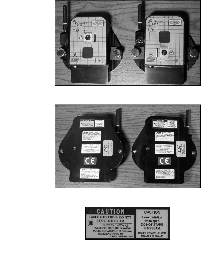
The 8215/8225 Laser Alignment Fixtures use a Class II (CDRH)
laser or Class 2 (IEC) laser. This laser complies with 21 CFR
1040.10 and 1040.11 safety requirements with a power output < 1.0
mW (average) and a pulse repetition of 600 pulses/sec. The pulse
duration is <110 microseconds. However, do not expose the human eye
directly to the laser beam! Warnings are located on each sensor head.
Caution!
Using the controls or adjustments in ways other than specified in this
documentation may result in hazardous laser radiation exposure.
Making the hardware, firmware, or software perform in ways other
than specified in this documentation may result in hazardous laser
radiation exposure.
52
4-2 Setting Up and Using Laser Alignment Fixtures
Laser heads, front view
Laser heads, rear view
Laser radiation caution

4-3
Note
Operation is subject to the following two conditions: (1) this
device may not cause interference, and (2) this device must
accept any interference, including interference that may cause
undesired operation of this device.
Note
This equipment has been tested and found to comply with the
limits for a Class A digital device, pursuant to Part 15 of the
FCC Rules. These limits are designed to provide a reasonable
protection against harmful interference when the equipment is
operated in a residential environment. This equipment gener-
ates, uses, and can radiate radio frequency energy and, if not
installed and used in accordance with the instruction manual,
may cause harmful interference to radio communications.
Operation of this equipment in a residential area is likely to
cause harmful interference in which case the user will be
required to correct the interference at his own expense.
Caution!
Changes or modifications not expressly approved by CSI could void the
user's authority to operate the equipment.
Caution!
This device has been designed to operate solely with the antenna type
provided, CSI part number 88200. An antenna having a higher gain
is strictly prohibited per regulations of Industry Canada.
4-4 Setting Up and Using Laser Alignment Fixtures
General Description
Sensor Head Description
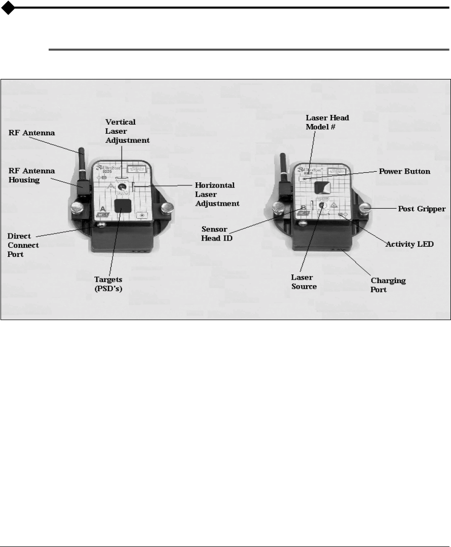
The sensor head with the laser source on top is the “Master” head (known
as head “A”). The other head is the “Slave” (known as head “B”). The model
number is listed on the back of each head. They can be identified by the
letter A or B on the front.
The difference between the Model 8215 sensor heads and the 8225 sensor
heads are the target (PSD) size, laser distance, and the front overlay. The
8215 sensor head has a 10mm x 10mm PSD with a 30’ laser while the 8225
sensor head has a 20mm x 20mm PSD with a 100’ laser.
The Activity LED on the front panel can be red, yellow, or green. An expla-
nation of their meaning is shown in the following table.

4-5
General Description
LED Status Meaning Required Action
Green Yellow Red
X
Normal Operation - When the
Laser Head systems are all
functioning properly and the
laser beam from the
companion Laser Head is
striking the PSD in the linear
region. This is the desired
state. The Laser Head is in the
acceptable condition to
perform an alignment.
No Action Required
X (flashing)
Sensor head in standby (sleep)
mode - When the Laser Head
sees no activity for five
minutes, they automatically
places themselves in Sleep
Mode to conserve battery
power. The color will be the
one that was active, solid or
flashing, before this state was
entered. When this sleep
mode is entered, the LED will
be flashed off for 1.5 sec. and
on for 0.5 sec.
Use analyzer to wake up
when needed by initiating
communication with the laser
heads.
X
Minor Error* Refer to “Laser Head Status
Screen” on page 3-8 for more
information on the error and
the required action.

4-6 Setting Up and Using Laser Alignment Fixtures
* If a minor error is present, the data being acquired may be marginal. The
data quality will depend on the error. If a major error is present, then some
kind of hardware or system problem exists. Therefore, the data being
acquired is rejected.
X (flashing)
Low battery 1st warning
(sensor head) - The Laser
Head has the ability to
monitor its own battery
power. The battery power is
checked periodically to
determine if it is below the
minimum acceptable power.
When the battery power
reaches 4.8 volts, the LED will
be flashed off for 0.5 sec. and
then flashed on for 0.5 sec.
Data is accepted when the
battery is this state.
Recharge sensor heads.
X
Major Error* Refer to “Laser Head Status
Screen” on page 3-8 for more
information on the error and
the required action.
X (flashing)
Low battery 2nd/final warning
(sensor head) - The Laser
Head has the ability to
monitor its own battery
power. The battery power is
checked periodically to
determine if it is below the
minimum acceptable power.
When the battery power
reaches 4.2 volts, the LED will
be flashed off for 0.5 sec. and
then flashed on for 0.5 sec.
Data is not accepted when the
battery is this state.
Recharge sensor heads.
LED Status Meaning Required Action
Green Yellow Red

4-7
General Description
LED Functionality Difference Due to Dual Pass mode
The functionality of the LED differs slightly from the states described in the
above table when the Dual Pass mode of operation is selected. The differ-
ence lies in the LED state when the companion Laser Heads laser beam is
on the PSD. In Dual Pass mode, when the laser beam is on or off of the PSD
the LED will be a solid yellow, EVEN WHEN THE BEAM IS IN THE
LINEAR PORTION OF THE PSD. The beam will then flash to green
whenever a valid data point is acquired. This deviation is necessary to allow
for the indication to the user that the Laser Heads are acquiring data as they
are rotated past each other.
Note
To determine the actual error, press the Options key, then
Laser Head Status (on the UltraSpec analyzer). This will acti-
vate the Laser Heads Status screen (next graphic). If an error
condition actually exists, its type will be shown in a popup
window within 60 seconds. Refer to “Laser Head Status
Screen” on page 3-8 for more information.

4-8 Setting Up and Using Laser Alignment Fixtures
General Maintenance
Additional maintenance information is located in Chapter 10.
Care and Handling
To ensure satisfactory service from this system, follow these procedures:
• Keep the mounting base and chain mounting posts lightly oiled to
prevent them from corroding.
• To maintain repeatability and accuracy, avoid dropping fixture
items. Refer to the Customer Assistance section for repair, update,
and calibration.
• Do not subject system items to large temperature swings.
• Do not engrave on the sensor heads.
• Keep all lens free of grease, dirt, oil, and other smudges.
• Clean the laser and target lens with a soft, lint-free cloth and standard
lens cleaning solution (a field size cleaner container is available from
CSI). Never use an organic solvent such as a thinner or benzine.
• Store sensor heads in protective drawstring bag when not in use.
Calibration
The Model 8215/8225 calibration should be checked every two years.
Return the sensor head to CSI for a calibration check. All calibrations are
NIST traceable.
Warning!
Do NOT remove the CSI Quality label on the back of the
sensor head. This will VOID your warranty.
4-9
General Maintenance
Battery Charging
Batteries may be charged with the Model 8211 or the Model 8212. The
Model 8211 is a “smart, drop-in” charger that can provide a fast- or trickle-
charge for the laser heads and analyzer. In fact, it can discharge the laser
heads, if necessary. The Model 8212 is an “overnight” trickle-charger that
can only trickle-charge laser heads and the analyzer.
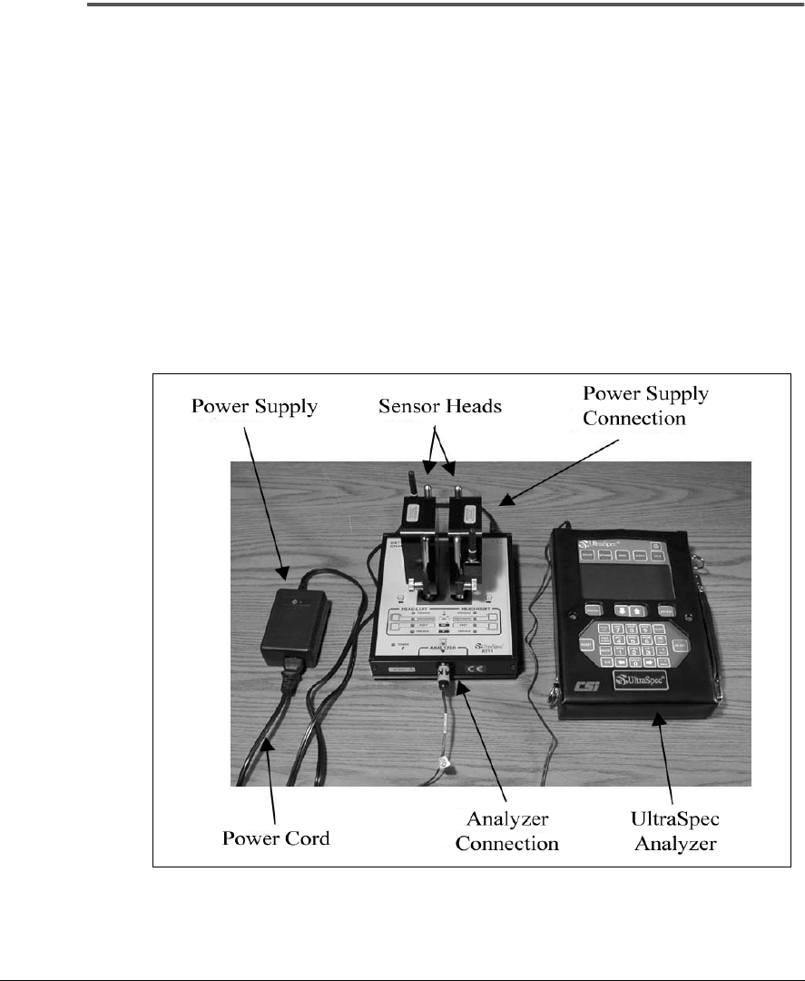
Model 8211 Smart Charger
The Model 8211 provides all battery charging needs and comes with the
system. It is a “smart, drop in” charger for the laser heads; it will also charge
the analyzer when plugged into a cable. The following picture shows both
of the laser heads
and
the UltraSpec analyzer being charged.
Charging the Sensor Heads and Analyzer with Model 8211 Charger

4-10 Setting Up and Using Laser Alignment Fixtures
To set up the 8211, complete these steps:
1. ··· Plug the power cord into the power supply.
2. ··· Plug the power cord into an AC receptacle.
3. ··· Plug the power supply into the 8211 in the top end cap.
At that time, the beeper will sound indicating that power has been applied
to the battery charger. As a test, all LEDs will illuminate for 1.5 seconds.
4. ··· Plug the analyzer charging cable into the bottom end cap.
The sensor heads and analyzer can now be charged either individually or,
all at the same time.
Warning!
Do not plug the 8211 Power Supply directly into the
UltraSpec analyzer. If you do, the equipment may be
severely damaged.
Charging the Sensor Heads with the Model 8211 Charger
Drop them over the posts so that the head faces outward as shown in
“Charging the Sensor Heads and Analyzer with Model 8211 Charger” on
page 4-9. Heads can be charged individually or together.
Indicator Light Charging Status
Pending Waiting for safe voltage and
temperature
Discharge (steady) Batteries discharging
Discharge (flashing Discharge requested, waiting
for safe voltage or temperature
Fast (steady) Batteries in fast charge
Fast (flashing) Fast charge requested, waiting
for safe voltage or temperature
Trickle Batteries in trickle charge,
topping-off, or charge complete