Computational Systems orporated 8000RF Laser Alignment Fixture User Manual Chap 4 pp 11 to 40
Computational Systems Incorporated Laser Alignment Fixture Chap 4 pp 11 to 40
Contents
Chap 4 pp 11 to 40

4-11
General Maintenance
For maximum safety, the battery charger has a “Pending” status LED,
which lights momentarily when the head is first placed on the charger. If a
battery is very low, or is out of a specific temperature range, it cannot be
safely charged. When this condition occurs the “Pending” indicator
remains light. While “Pending,” the charger is actually charging the bat-
teries at a very low rate. This brings the low battery into acceptable voltage
range. Once the battery temperature and voltage are suitable for charging,
the charger automatically begins trickle charging and the “Trickle” indi-
cator light turns on.
To fast charge or discharge the battery the “Fast” button or “Discharge”
button must be pressed. If the “Fast” button or “Discharge” button is
pressed while the battery voltage is too low or temperature is not suitable
for “Fast” or “Discharge” operation, the indicator light will flash on and off.
This response acknowledges the request but indicates that the charger
cannot follow the request at that time. Once voltage and temperature con-
ditions are suitable, the requested “Fast” or “Discharge” operation will
begin and the indicator light will change to a steady light.
Warning!
Note that if the battery is fully charged, a user is able to
initiate fast charge by pressing the “Fast” button. After
about 2 minutes, the charger will stop fast charge in this
case. However, to avoid overcharging batteries, you
should not press the “Fast” button with an already fully
charged battery.
After the “Fast” charging cycle has completed the charger beeper will
sound and automatically begin trickle charging. When this condition
begins the “Trickle” indicator light turns on indicating that the battery is
almost completely charged or is completely charged. For the laser head bat-
teries, the two conditions occur within a few minutes of each other. Charge
time from a fully discharged set of batteries to approximately a 90% voltage
charge is 15 minutes.

4-12 Setting Up and Using Laser Alignment Fixtures
After the “Discharge” cycle has completed the charger automatically begins
fast charging and the “Fast” indicator light turns on. To avoid the battery
memory concern, use the “Discharge” mode when you have more than 20
minutes to charge the sensor head batteries. The typical charge cycle is as
follows:
Note
After power has been applied to the charger and the sensor
head have been placed in it, if none of the LED's for that sensor
head are lit then the contact between the sensor head and
charger may not be sufficient enough to charge the batteries.
No LED's lit indicates a “no battery present” state. If this
occurs, remove the sensor head from the charger and try
reseating it back into the charger.
Note
After a charging cycle has begun, if that charging cycle is inter-
rupted (e.g. disconnecting the power to the charger or
removing the sensor head from the charger) the charging pro-
cess described above begins again from the beginning. There-
fore, if the charger cycle is interrupted while the “Fast” charge
mode is in progress then the charger will then automatically
begin trickle charging after “Pending.”
Action Time
Press DISCHARGE button Start
DISCHARGE complete, FAST starts 7 minutes
FAST complete, TRICKLE starts – charging complete 22 minutes
NOTE:
The heads can be left on TRICKLE indefinitely (until the next time they are
needed).

4-13
General Maintenance
“Pending LED” will light momentarily and switch into FAST charge.
Charge time for a fully discharged set of batteries is 15 minutes. The beeper
will sound when both heads are fully charged and have switched to
TRICKLE charge. To avoid the NiCad battery memory concern, use the
DISCHARGE mode when you have more than 20 minutes to charge the
sensor head batteries.
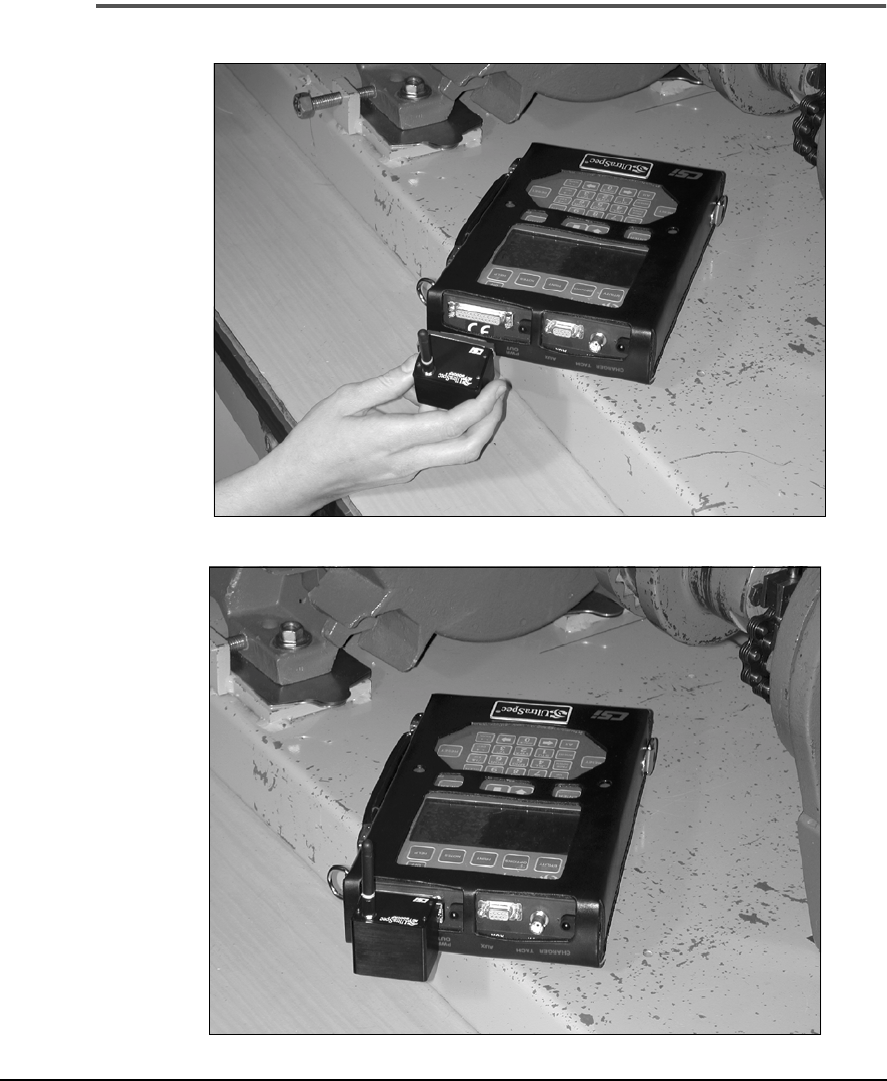
Charging the UltraSpec 8000 Analyzer with the Model 8211 Charger
Plug the charging cable (A821101) from the bottom end cap on the 8211
(earlier than Rev. 4) into the top of the analyzer. TRICKLE mode will start
the charge cycle. To change to FAST mode, press the FAST button in the
Analyzer section. The analyzer battery is not monitored but utilizes a timer
to avoid overcharging. The 8211 will charge the analyzer in FAST mode for
15 hours or until the FAST button is pressed again (whichever comes first).
If the 8211 charger is Rev. 4 or later, it cannot be used to charge an
UltraSpec 8000 analyzer.
Charging the Model 8117 Analyzer with the Model 8211 Charger
Plug the charging cable (A821102) from the bottom end cap on the 8211
into the charger port on the top end cap of the 8117 analyzer. The battery
pack will recharge in 14 to 16 hours. If the batteries are continually allowed
to remain on charge for longer than 16 hours, battery degradation will
occur. Overnight charging is allowable, however, charging over a weekend
is not recommended.
Charging the Model 2120 Analyzer with the Model 8211 Charger
Plug the charging cable (A821102) from the bottom end cap on the 8211
into the charger port on the top end cap of the 2120 analyzer. The battery
pack will recharge in two and one half hours. After the battery pack has
been fully charged, the battery charger will automatically switch to a trickle
charge.
4-14 Setting Up and Using Laser Alignment Fixtures
Model 8212 Trickle Charger
The Model 8212 battery charger is a trickle charger for the laser heads and
the Model 8117 UltraSpec analyzer. It will charge the laser heads and ana-
lyzer in ten hours. This is intended to be an overnight charge. The laser
heads should not be left on charge over 24 hours. Continual overcharging
the batteries will result in a shortened life.
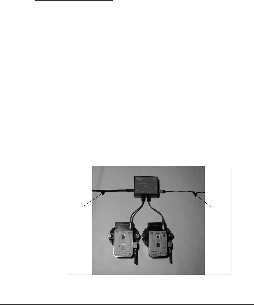
To set up the Model 8212 charger, complete the following steps:
1. ··· Plug the power cord into the power supply that came with the 8117 or
2120 analyzer.
2. ··· Plug the power cord into an AC receptacle.
3. ··· Plug the power supply into the Power connection on the 8212. Ensure
the associated LED illuminates.
4. ··· Plug the laser heads into the A and B pigtails from the 8212. Ensure
the associated LEDs illuminate.
5. ··· To charge the analyzer, plug the 821102 charge cable into the
analyzer connector on the 8212. Ensure the associated LED on the
8212 illuminates.
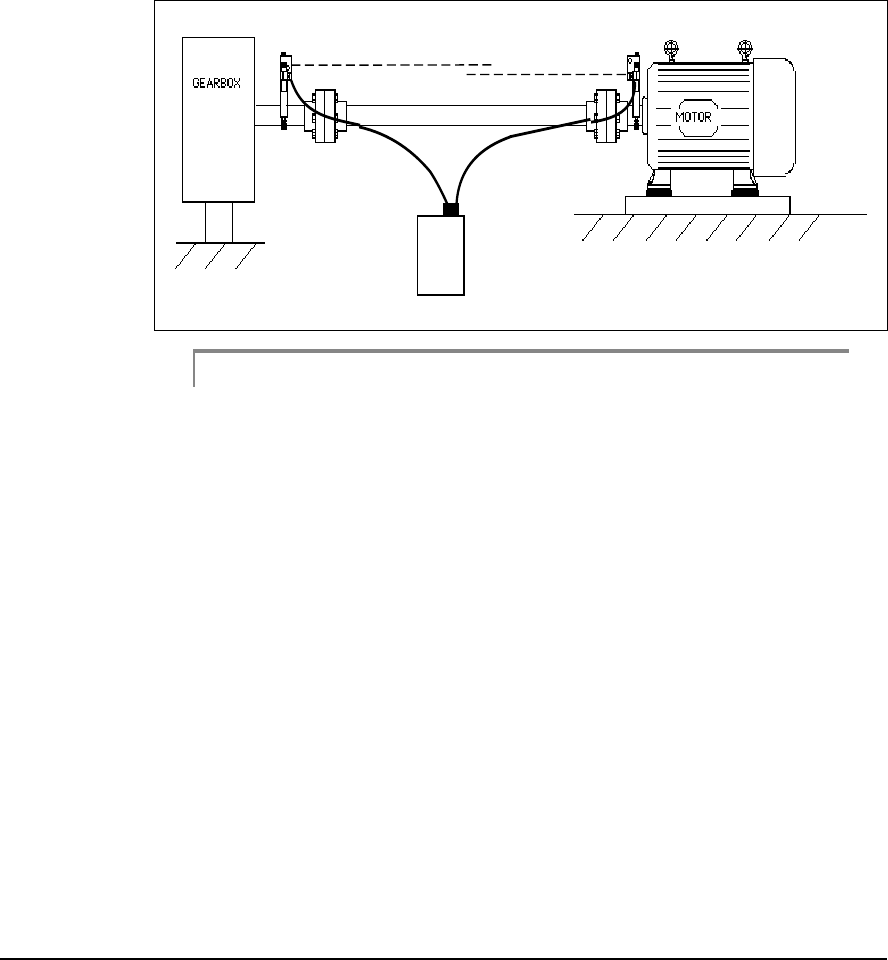
See the photo below that illustrates the 8212 setup with a pair of laser heads
and a Model 8117 UltraSpec analyzer.
Charging the Model 8215 Laser Heads with the Model 8212 Charger
From
Power
Supply
To 8117
Analyzer

4-15
General Maintenance
Charging the Model 8117 and 2120 Analyzers with the Model 8212 Charger
After plugging the charging cable (A821102) into the 8212, plug the other
end of the cable into the charger connection on the top end cap of the
Model 8117 or the Model 2120 analyzer. Ensure the LED on the analyzer
illuminates, if applicable. The Model 8117 battery pack will recharge in 14
to 16 hours. If the batteries are allowed to continually remain on charge for
longer than 16 hours, battery degradation will occur. Overnight charging is
allowable, however, charging over a weekend is not recommended. The
Model 2120 battery pack will recharge in two hours then switch to a trickle
charge that will not damage the battery.
Charging the Model 8000 Analyzer with the Model 8212 Charger
The Model 8212 trickle charger CAN NOT charge an UltraSpec 8000 ana-
lyzer. To charge the 8000 use either a Model 8211 (previously discussed in
this section) or the Model 2115-C-120 wall charger. This includes the safety-
rated UltraSpec 8000 analyzer.
Note
See “UltraSpec 8000 Analyzer Battery Recharge” on page 9-6
and “UltraSpec 8117 Analyzer Battery Recharge” on page 9-9
for information on optional methods of charging the UltraSpec
analyzer.

4-16 Setting Up and Using Laser Alignment Fixtures
Battery Usage - Laser Heads
A rechargeable battery pack is used to power each sensor head. A fully
charged battery pack will give 3 to 4 hours of continuous service while
transmitting data. Longer operation is possible since typical alignments do
not require continuous communication with the analyzer. The battery is
designed to have a long life and is not intended to be replaced by the user.
Replacement should be performed only at CSI. CSI recommends that the
batteries be replaced after 1,000 charges/discharges.
To conserve battery life, the 8215/8225 has a sleep mode and a shutdown
mode. The sleep mode is activated after 5 minutes of no communication
with the analyzer. In the sleep mode, the laser beam and RF communica-
tion are shutdown until communication is reestablished. All data in
memory is saved. In the auto-shutdown mode, the sensor heads are com-
pletely shutdown. The POWER button will start the sensor heads again. All
data in memory is lost, therefore another sweep should be taken.
The sleep and auto-shutdown modes can be disabled. When turning the
sensor heads on, press and hold down the POWER buttons (the LEDs will
turn on when the POWER buttons are first pressed). The LEDs will turn
off when the sleep mode is disabled (approximately 3 seconds). When both
LEDs light again, the shutdown mode will be disabled (approximately 5
seconds). Refer to “Laser Head Status Screen” on page 3-8 for more details.
Note
Please note that this disables the battery conservation (for the
sensor heads) therefore, if the heads are left on, the batteries
will run down.

4-17
Precautions
Precautions
Please follow these precautions carefully. Any product damage due to these
conditions may void the warranty.
•
Do not
change the battery pack with the battery charger connected as
damage may occur to the analyzer.
• Use only CSI-supplied battery chargers that have been approved for
use with UltraSpec analyzers and Model 8215/8225 laser heads. The
use of any other charger will most likely damage the equipment.
• Do not use CSI battery chargers with anything other than what they
are designed for! Do not use the 8211 or 8212 to charge anything else!
• Do not repeatedly overcharge the analyzer batteries. If the batteries
are continually allowed to remain in the “Fast” charge cycle for
periods longer than the recommended 14 to 16 hours, battery degra-
dation will occur.
• Do not use any batteries other than those included and/or specified
for UltraSpec analyzers and 8215/8225 laser heads.
• Do not connect a signal larger than ± 21 volts into the input of the
analyzer.
• Do not connect any signal other than a TTL-level signal to the
tachometer input. Other signals may damage the analyzer.
• Do not connect a printer directly to the RS232 port located on the
top panel of the analyzer.
• Do not connect any adapters or accessories to the RS232 port
located on the top panel of the analyzer while the analyzer is turned
on.
• Do not start the machines being aligned with the laser alignment
system equipment attached. Be sure to remove the laser system
before starting the machinery.

4-18 Setting Up and Using Laser Alignment Fixtures
Introduction to Laser Alignment Fixtures Setup
This section takes you through a step-by-step setup of the UltraSpec 8215/
8225 Laser Alignment Fixtures. Before performing alignment, be sure all
pre-alignment checks have been completed.
Caution!
Prior to mounting the laser alignment fixtures on machine shafts, all
switches operating the machines should be “locked out.” Follow safety
precautions for your facility. Normally, only personnel performing the
alignment should be able to “unlock” any startup switch. After an
alignment has been completed, the work area should be inspected to
ensure that all equipment is clear of rotating shafts/couplings, prior to
removal of the lockout protection.
Caution!
The 8215/8225 Laser Alignment Fixtures use a Class II (CDRH)
laser or Class 2 (IEC) laser. This laser complies with 21 CFR
1040.10 and 1040.11 safety requirements with a power output < 1.0
mW (average) and a pulse repetition of 600 pulses/sec. The pulse
duration is <110 microseconds. However, do not expose the human eye
directly to the laser beam! Warnings are located on each sensor head.
Water vapor or dust can interfere with a target “seeing” its laser. The air
between the sensor heads should be visually clear. Take care to ensure that
the air between the sensor heads is not being heated from steam leaks, unin-
sulated piping, etc. Heated air rising within the span between the sensor
heads can refract the laser beams and cause errors in the alignment read-
ings.
Operate the laser fixtures at ambient temperatures. If the fixtures have been
stored at a different temperature than the ambient temperature, allow the
laser fixtures to reach ambient temperature. Ensure that any heat source
that may be present is not creating a large temperature difference between
the laser fixtures and the ambient temperature. Sunlight itself will not cause
a laser reading problem.
4-19
Attaching the Fixtures
Attaching the Fixtures
This section shows how to attach and secure the mounting base, chains,
align the two mounting bases by leveling, install the sensor heads, turn on
the sensor heads, and center the lasers on their targets.
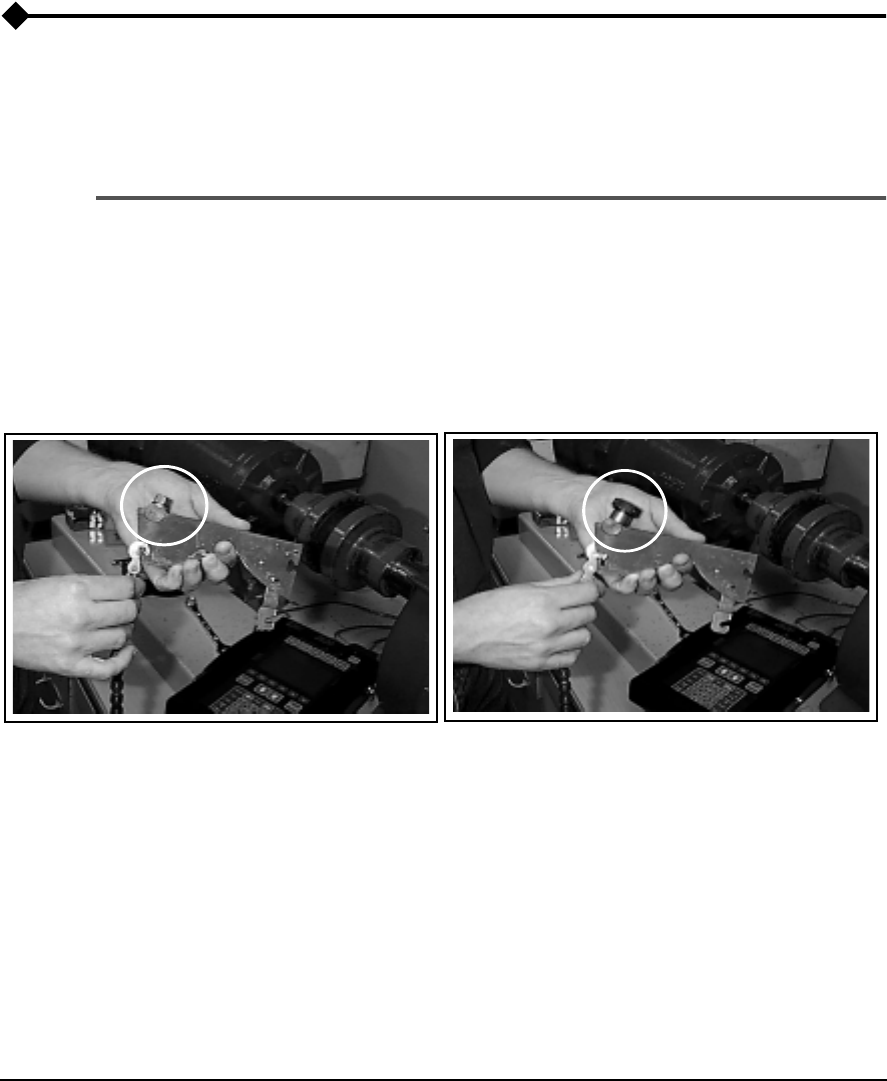
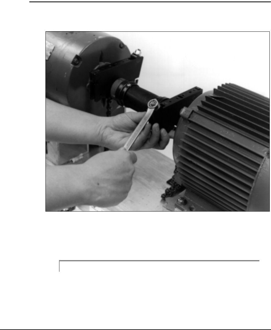
Attaching Chain to the Mounting Base
Select the chain tightener of choice. The left photograph shows a standard
hex nut which should be tightened with a 9/16 inch wrench. The right pho-
tograph shows a knurled nut which can be tightened by hand. The hex nut
mechanism provides a more stable, versatile mounting while the knurled
nut is more convenient. Use each nut as shown.
These photographs show how the chain assembly should be slipped into
the mounting base. Hold the chain out away from the base and slip the cyl-
inder into its cradle. To ensure maximum tightening range, each nut should
be flush with the end of the tightening bolt.
Standard Nut Knurled Nut
4-20 Setting Up and Using Laser Alignment Fixtures
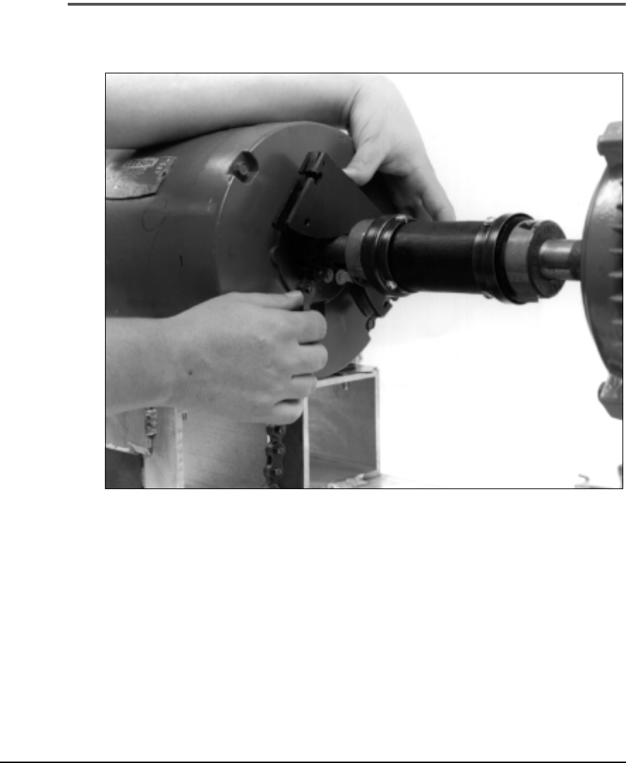
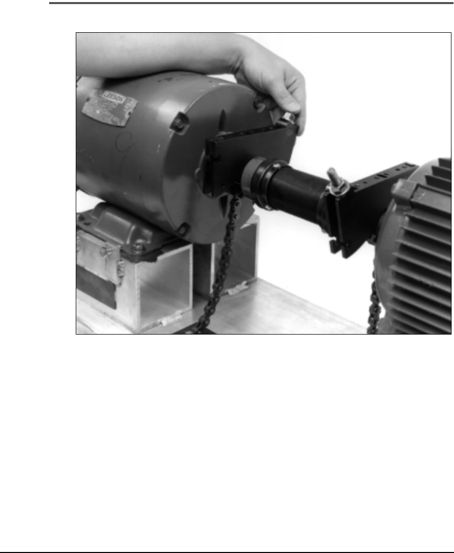
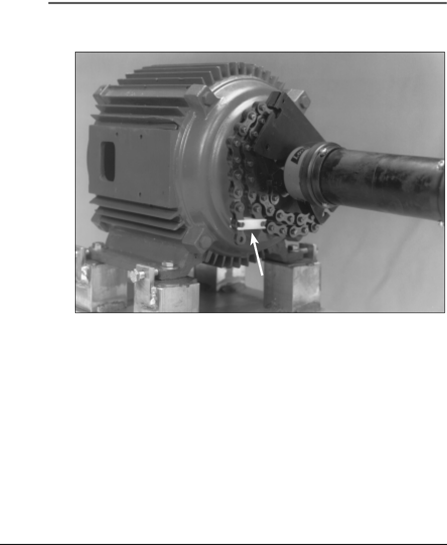
Attaching Chain to the Chain Pickup
This photograph shows how the chain attaches and actually clamps the
shaft. After slipping a chain link into the chain pickup, tighten the bolt at
the end of the chain.
4-21
Attaching the Fixtures
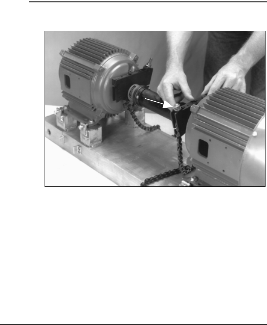
Allowing Maximum Tightening Range
To allow for maximum tightening range, ensure that the chain nut is flush
with the end of the chain bolt (as shown by arrow). Notice that the chain
bolts are on opposite sides. As shown in later sections, each mounting base
can be installed on either end and the chain bolts placed on either side of
the shaft.
4-22 Setting Up and Using Laser Alignment Fixtures
Positioning a Mounting Base
Tighten one of the mounting bases and rotate it (along with the shaft) until
it is somewhat level at the top of the rotation.
To tighten the mounting base, use
a 9/16 inch wrench or your hand, depending on which chain tightener is being used
.
Caution!
Do not overtighten the chain – the maximum tightening torque is 10
ft.-lbs.
4-23
Attaching the Fixtures
Positioning the Other Mounting Base
With the previous mounting base still in its level position, if necessary,
loosen and rotate the other mounting base until it is somewhat level with it.
Tighten this base and recheck the other base to ensure that both bases are
now level with each other.
Although this part of the procedure is not absolutely critical, placing the
mounting bases relatively level with each other allows the laser beam
adjustment to be more or less centered. This ensures that the laser beams
can line up with their targets easily.
Also, there may be times when the top position is not accessible. The objec-
tive of this step is to mount the sensor heads in the same rotational position.
This provides the maximum sensor range during data acquisition.
4-24 Setting Up and Using Laser Alignment Fixtures
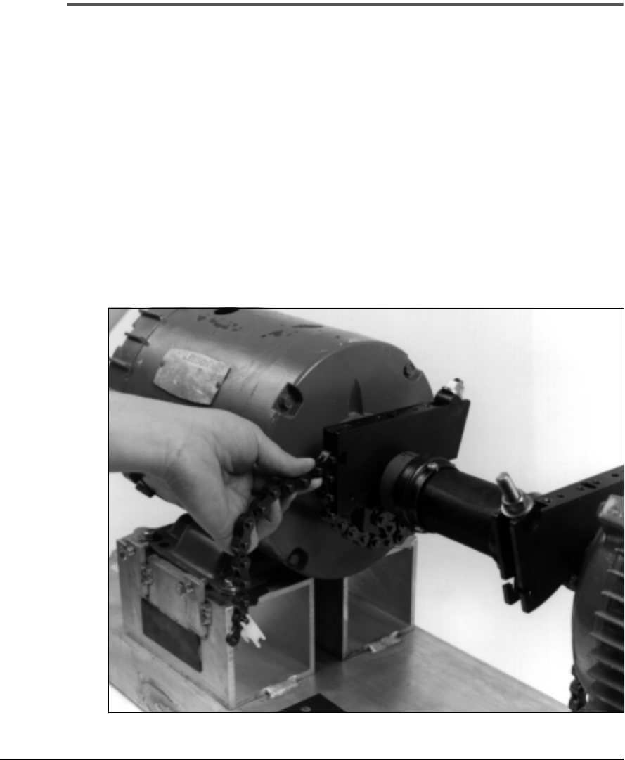
Attaching Excess Chain
One of the problems with using chains as a mounting bracket is that the
excess chain flops and can cause errors. UltraSpec laser alignment fixtures
provide solutions for this problem.
Two slots are provided (one on either side) to take up the slack. As shown
in the following photographs, you can use either or both of the slots as
needed. The order of use is not important. In fact, the L-slot cannot be used
when mounting to shafts (or couplings) greater than 3 inches (76 mm) in
diameter. When fastening the chain into the T-shaped slot, the rubber block
will hold the chain in place.
The photograph below illustrates using the T-shaped slot; use of the L-
shaped slot is shown on the next page.
Using the T-shaped Slot
4-25
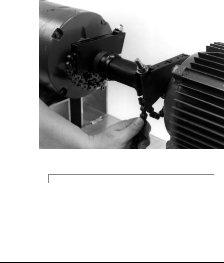
Attaching the Fixtures
Using the L-shaped Slot
Caution!
Do not attach excess chain prior to tightening the mounting base chain
bolts. Doing so may cause damage to the L and T-shaped slots.
4-26 Setting Up and Using Laser Alignment Fixtures
Using the Chain Clip
You will almost always have a little extra chain left over. In that case, use
the chain clip to attach it to the previous chain loop. CSI recommends that
you use this clip to help prevent the chain from sliding out of the L-slot as
the shafts are rotated.
4-27
Attaching the Fixtures
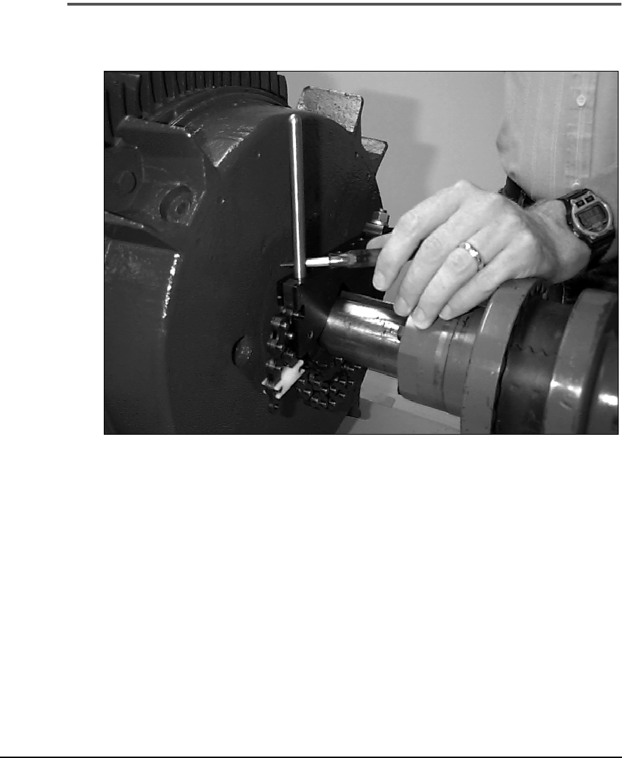
Installing a Post
Screw a post into each of the outer holes in the mounting base. Tighten each
post with the supplied tightener (Phillips screwdriver) or with a 1/8 inch
Allen wrench (not supplied with kit).
4-28 Setting Up and Using Laser Alignment Fixtures
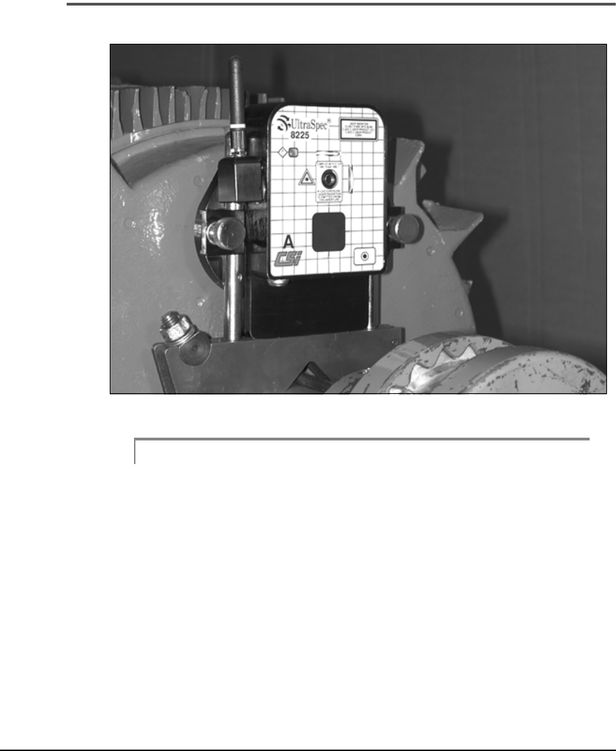
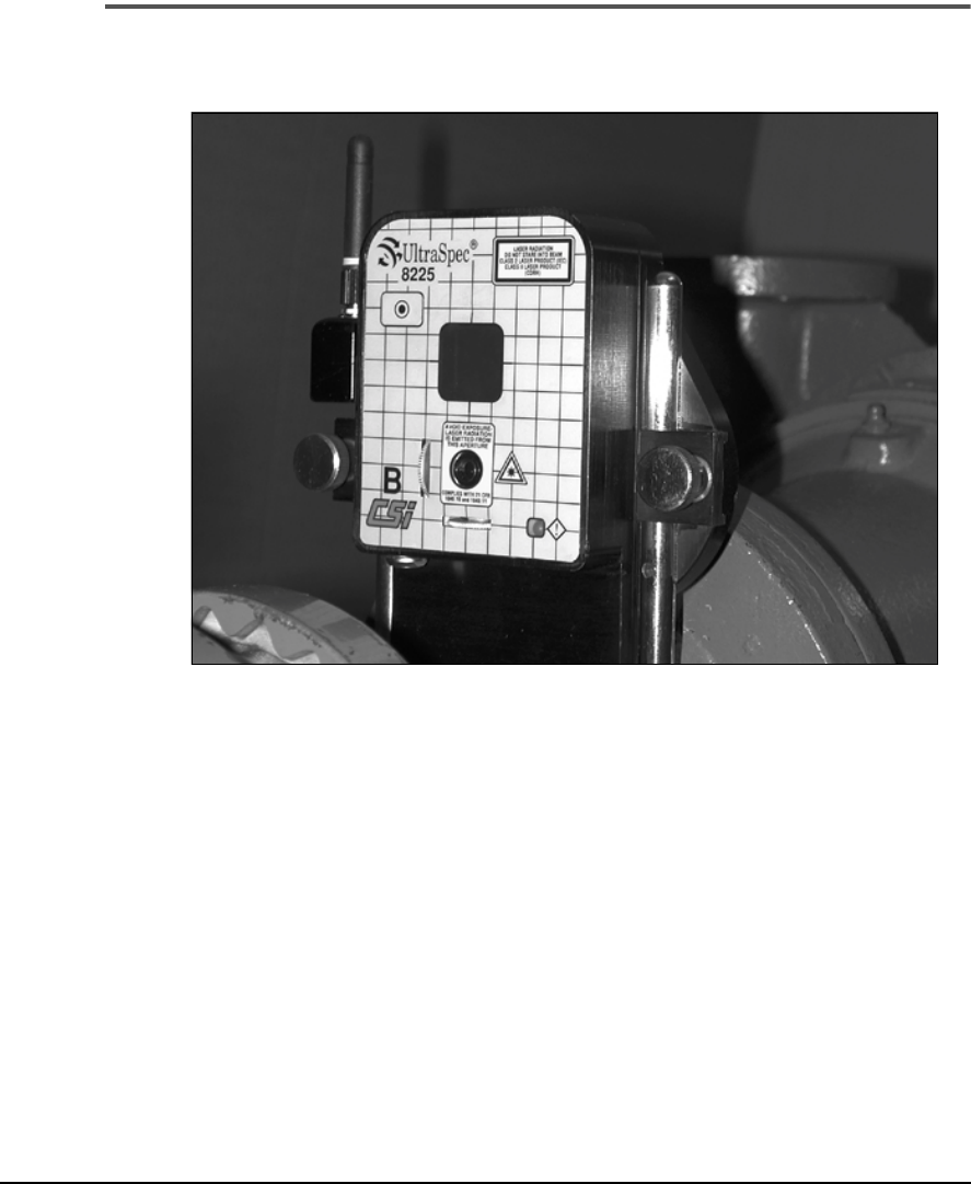
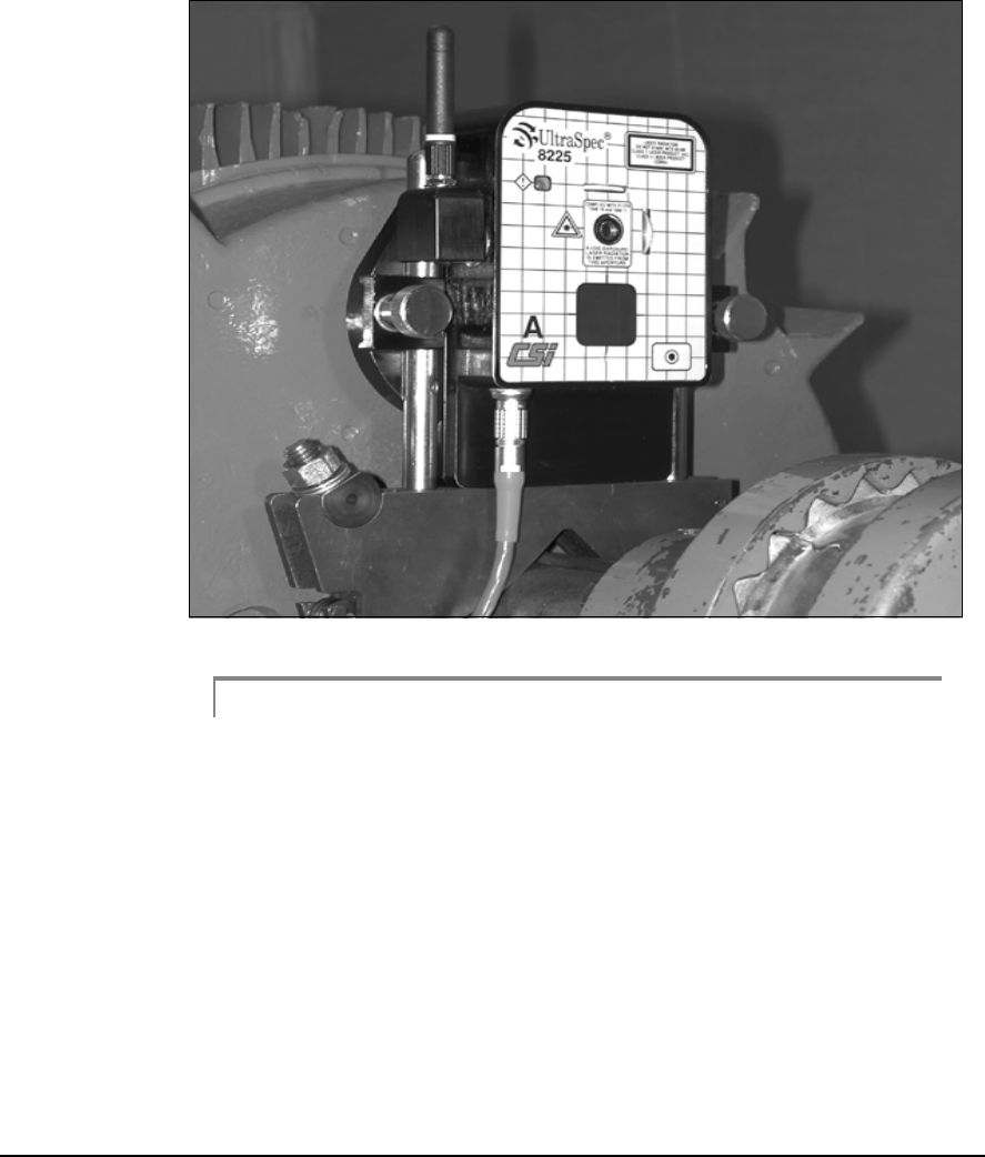
Mounting a Sensor Head
Note
Head A and B are identified with letters on the front panel.
Place a sensor head on the two posts. It does not matter which side of the
coupling Head A or Head B is mounted on – the heads will be configured
in the analyzer. Adjust to desired position and tighten each post clamp
finger tight. The vertical posts allow up to 1.5 inches (38 mm) of vertical
adjustment. If more vertical adjustment is needed, use the vertical exten-
sion blocks. See “Introduction to Special Applications” on page 4-46
through “Adding a 2-inch Block” on page 4-48 for additional information.
4-29
Attaching the Fixtures
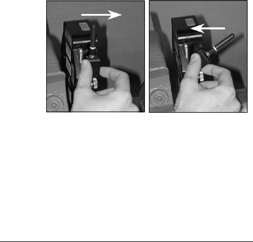
Depending on the clearance around which the laser head will be rotated,
the position of the RF antenna may have to be adjusted. When the antenna
is in its most upright position it extends up above the top of the laser head.
Holding the antenna housing (not the antenna itself), rotate or twist the
antenna down (or up depending on its starting position) to its desired pos-
tion. The antenna’s rotational arc is 30 degrees. When the antenna is in its
most downward position it does not extend up above the top of the laser
head.
1
4-30 Setting Up and Using Laser Alignment Fixtures
Mounting the Other Sensor Head
Install the opposite sensor head in the same manner (Head A or Head B,
depending on which sensor head was mounted on the other side).
4-31
Attaching the Fixtures
Connecting the 8000RF Interface
Attaching 8000RF to RS232 25-pin Serial Port

4-32 Setting Up and Using Laser Alignment Fixtures
Install the 8000RF Interface onto the RS232 serial port of the UltraSpec
analyzer by completing the following steps:
1. ··· Ensure that the UltraSpec analyzer is turned off.
2. ··· Connect the 8000RF Interface to the RS232 25-pin connector to the
UltraSpec analyzer.
3. ··· Turn the UltraSpec analyzer on.
Note
The RF antenna on the 8000RF Interface does not rotate or
twist. Therefore, trying to rotate or twist the antenna will only
result in damaging the 8000RF Interface.
4-33
Attaching the Fixtures
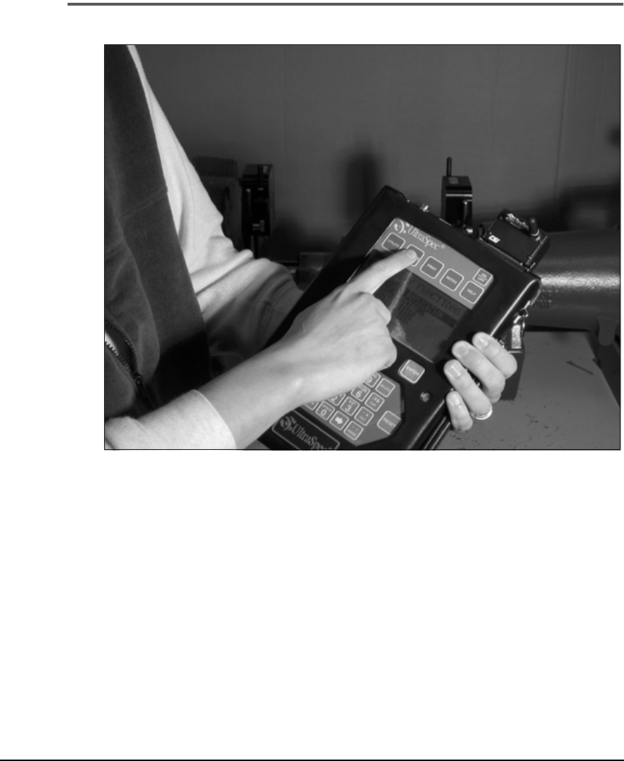
Starting the UltraSpec Analyzer
Turn on the UltraSpec analyzer by pressing the ON/OFF button located at
the top right of the Front Panel. This automatically takes you to the pro-
gram’s main menu. From the main menu, press the Options key. Select (4)
Alignment Setup and press Enter.
From the Alignment Setup menu, configure the alignment parameters.
(Refer to “Alignment Setup” on page 3-6 for details.) The default settings
are:
Method
– Auto Sweep
ACQ Mode
– Standard
Tolerance
– Angle/Offset
Thermal Growth
– No

4-34 Setting Up and Using Laser Alignment Fixtures
Foot Pre-Check
– Soft Foot
Quick Spec
– No
When finished, press Enter to accept any changes made. Finally, press the
Reset/Main key to return to the program’s Main menu.

4-35
Attaching the Fixtures
Communication Between the Fixtures and Analyzer
The UltraSpec analyzer conducts communication with the fixtures via a
short-range, low-power radio frequency (RF) carrier or by cable.
Communication
– With RF, communication occurs in much the same
manner as with other short-range wireless systems (e.g., cordless phones) –
a direct line of sight communication is not required.
A typical operating range of up to 50 feet can be achieved using RF com-
munication, but this range is greatly influenced by building construction
materials and contents, other radio systems operating in the vicinity at or
near the same operating frequency, and noise generated by nearby equip-
ment. It is not unusual to achieve four times the typical operating range in
electrically quiet environment or to achieve less then the typical operating
range in an electrically noisy environment.
Note
The RF operating frequency is 916.5 mHz.
Note
This equipment has been tested and found to comply with the
limits for a Class A digital device, pursuant to Part 15 of the
FCC Rules. These limits are designed to provide a reasonable
protection against harmful interference when the equipment is
operated in a residential environment. This equipment gener-
ates, uses, and can radiate radio frequency energy and, if not
installed and used in accordance with the instruction manual,
may cause harmful interference to radio communications.
Operation of this equipment in a residential area is likely to
cause harmful interference in which case the user will be
required to correct the interference at his own expense.
Caution!
Changes or modifications not expressly approved by CSI could void the
user's authority to operate the equipment.

4-36 Setting Up and Using Laser Alignment Fixtures
There may be times when an RF communication between each sensor
head and the UltraSpec analyzer is not convenient. Moving or keeping the
analyzer closer to the laser heads can minimize this inconvenience.
The sensor heads have memory for saving alignment readings. If commu-
nication with the UltraSpec analyzer is broken during rotation (while using
the Auto Sweep mode), these readings are stored in memory until they can
be transmitted. When the sensor head is turned off, the memory data is
erased.
If the UltraSpec analyzer is out of range of one or both sensor heads or if
some sort of RF interference is occurring, it will repeatedly attempt to com-
municate with the sensor heads. A message will be displayed on the ana-
lyzer until the communication link is established.
When communication using RF becomes difficult, CSI recommends that
you use the Direct Connect link as described in the following section.
4-37
Attaching the Fixtures
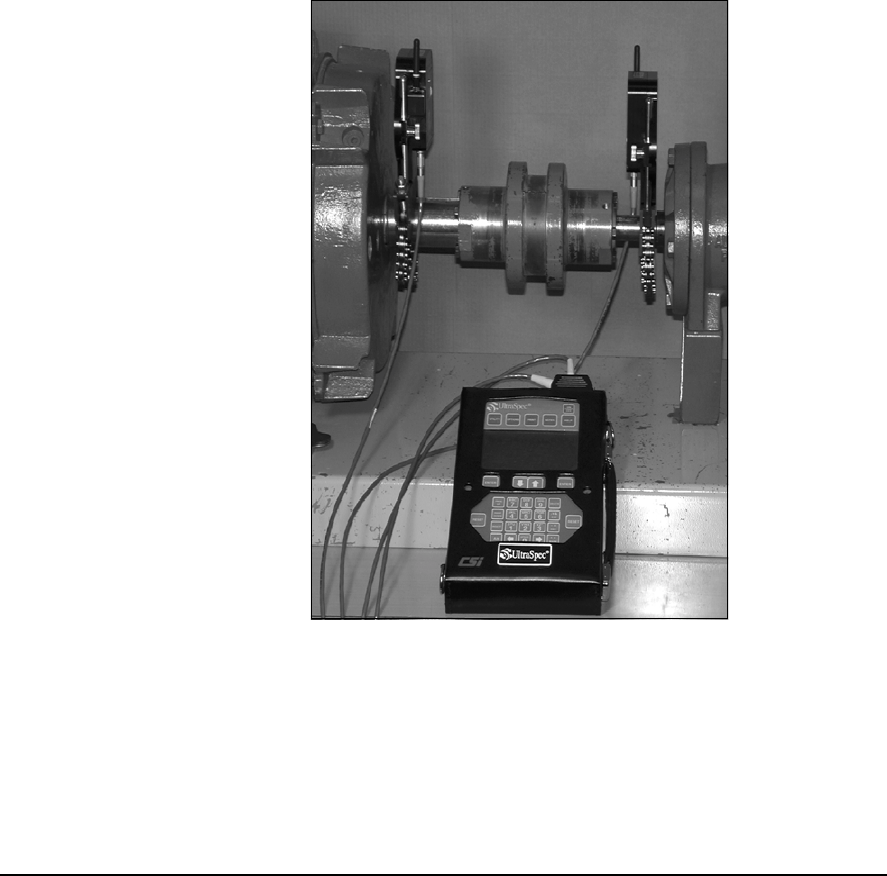
Direct Connect
Direct Connect is designed for those conditions where it is difficult to com-
municate between the analyzer and the sensor heads using RF. Conditions
such as building construction materials and contents, other radio systems
operation in the vicinity at or near the same operation frequency, and noise
generated by nearby equipment may make RF communication unsatisfac-
tory.
To use Direct Connect, complete these steps:
1.···· Make sure the UltraSpec analyzer is turned off.
2. ···Attach the 25-pin connector of the direct connect cable to the RS232
port on top of the analyzer.
3. ···Connect the Lemo connectors to the mating straight Lemo connector
on the extension cables.

4-38 Setting Up and Using Laser Alignment Fixtures
Note
When connecting the Lemo connector to its mating connector,
line up the red dots located on each connector with each other
before completing the connections.**
4. ··· Connect the Lemo connector on the opposite end of the extension
cable to the Lemo port under the nose of each 8215/8225.
Note
When connecting the Lemo connector to its mating connector,
line up the red dots located on each connector with each other
before completing the connections.**
Caution!
**To complete connection, push connecter together. DO NOT TWIST.
5. ··· Turn the UltraSpec analyzer on.
From this point on, Direct Connect is very easy to use. The analyzer deter-
mines that it is connected and disables the RF communication. Cables can
be unplugged and reconnected at any time (and at any connection). You do
not have to remember which cable is plugged to which head. Even if you
switch the orientation of the cables (when reconnecting), the analyzer can
adjust to the change and will still work correctly.
4-39
Attaching the Fixtures
2
Caution!
When using any cable connector inside the sensor head connector, DO
NOT turn or twist the connector. This will shear the cable pins off
(inside the connector) totally disabling the sensor head and cable. Pull
the cable connector completely out of the sensor head connector before
turning the cable.
4-40 Setting Up and Using Laser Alignment Fixtures
The extension cables are 10 feet (3 m) long. With the connection pigtail, the
total length is 12 feet (3.6 m). When standing between the sensor heads, a
20 feet (6 m) span can be aligned. Extension cables are available for longer
spans or, if you cannot stand directly in the middle.
Note
With the 8215, a maximum distance of 30 feet between the
laser heads can be achieved. With the 8225, a maximum dis-
tance of 100 feet between laser heads can be achieved.
UltraSpec
Analyzer