Computational Systems orporated 8000RF Laser Alignment Fixture User Manual Chap 4 pp 41 to 52
Computational Systems Incorporated Laser Alignment Fixture Chap 4 pp 41 to 52
Contents
Chap 4 pp 41 to 52
4-41
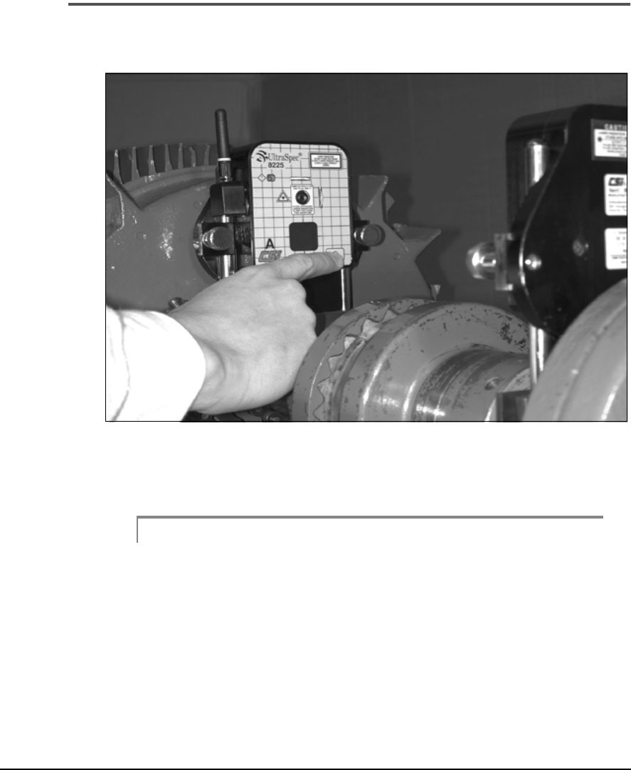
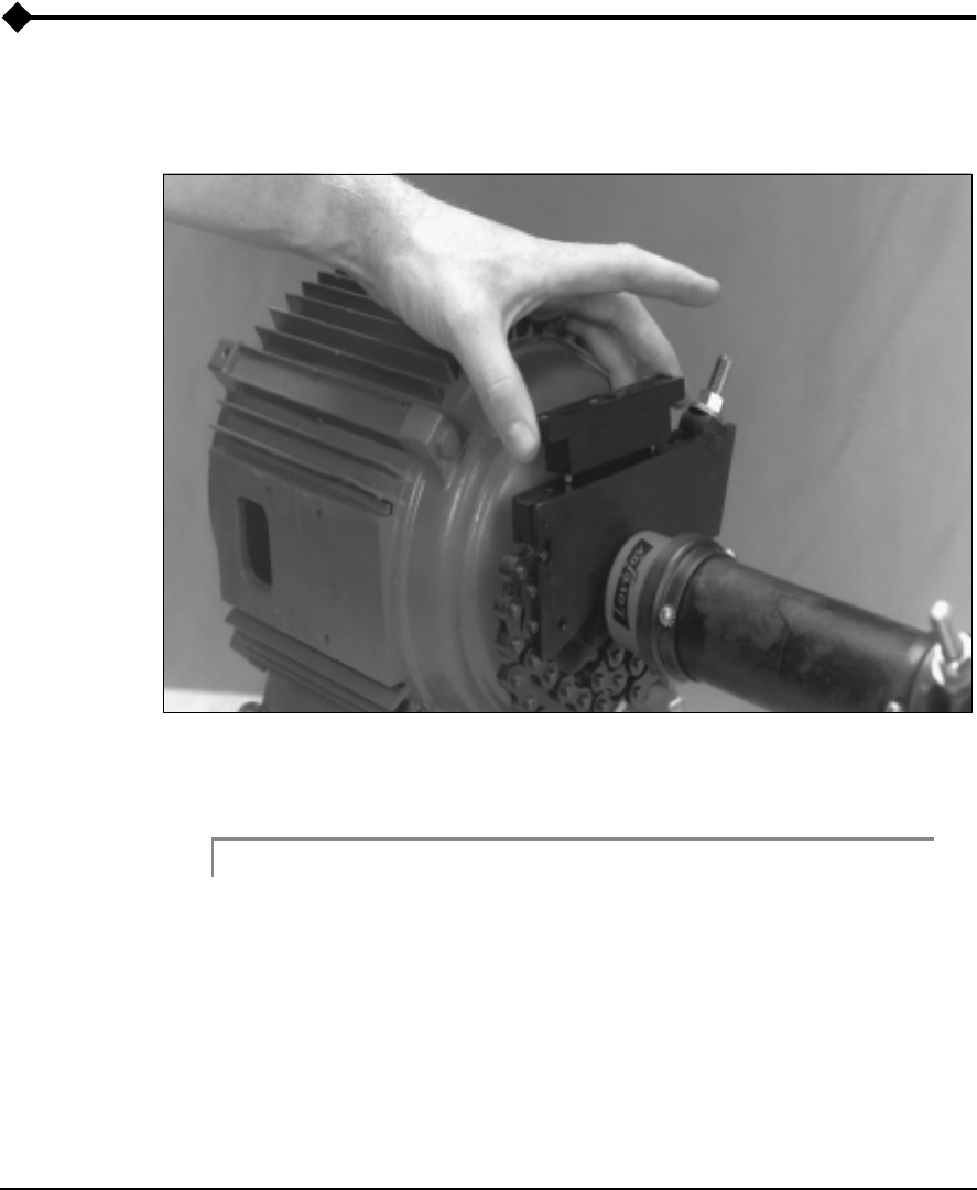
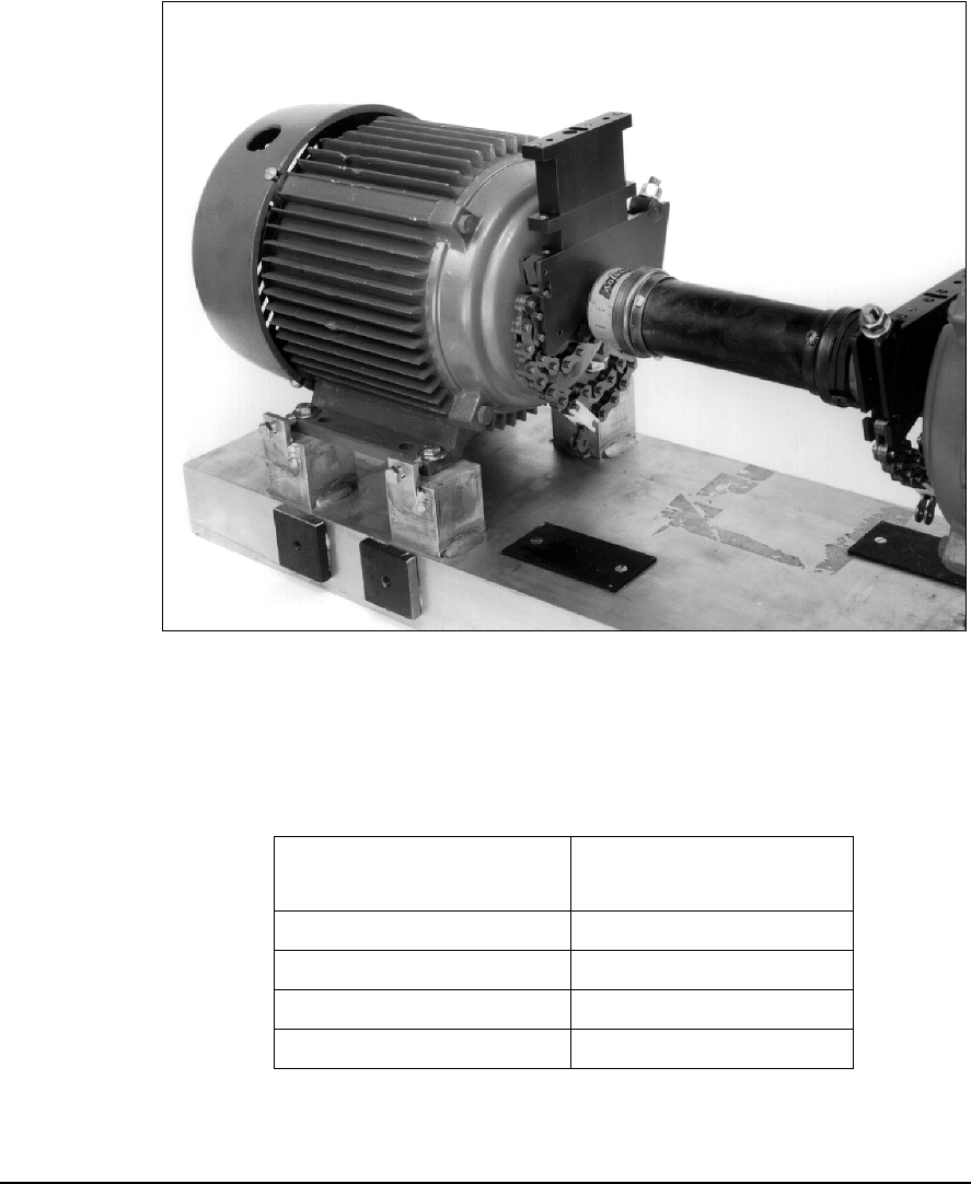
Attaching the Fixtures
Turn the Laser Beams on
To turn the laser beams on, press the power button on each sensor head.
See “Battery Usage - Laser Heads” on page 4-16 for power button options.
Caution!
Although the laser in the 8215/8225 system is low in intensity (
≤
1.0
mW), never direct the beam at a human eye. Use of controls, or adjust-
ments, or performance of procedures other than those specified by CSI
may result in hazardous laser radiation exposure. To do so could result
in serious personal injury. Always ensure that the sensor heads are
mounted securely before turning on the laser beam.
4-42 Setting Up and Using Laser Alignment Fixtures
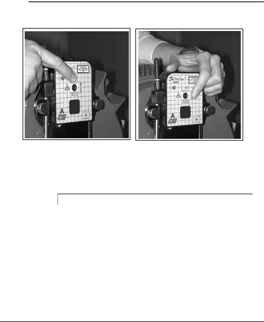
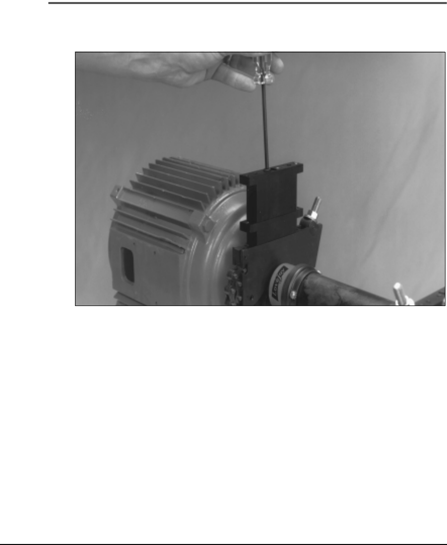
Center the Laser Beams
Vertical Adjustment Horizontal Adjustment
Center both Lasers on their associated target by adjusting the thumb wheels
on the front of each sensor head.
Note
If the movement is near the outer limits of its range in one
direction, you can gain additional movement by adjusting in
the opposite direction.
4-43
Attaching the Fixtures
Rough Alignment of the Laser Beams
Rough alignment may be required to keep the laser beam on the target as
the fixtures are rotated. Either of these methods can be used:
• Visible Beam rough alignment – utilizes the visible laser beams
without the use of the analyzer
• Partial Sweep rough alignment – utilizes the partial sweep capabili-
ties of the analyzer
Visible Beam Rough Alignment
This adjustment must be performed in each of the movement planes (typi-
cally horizontal and vertical, when required). A horizontal adjustment is
shown in the following figure; duplicate the actions for vertical adjustments.
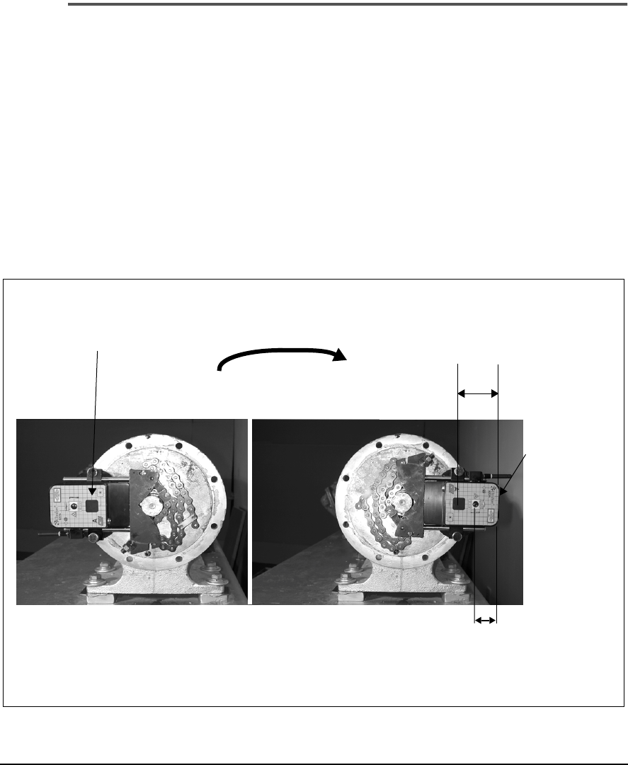
Rough Horizontal Laser Beam Adjustments
1. Center laser beams
in respective targets 3. Estimate distance
moved by laser beam
Laser beam
position after
heads have
been rotated
180°
4. Move machine to position
beams approximately half distance
back toward center of target
2. Rotate laser
heads 180°
.
.
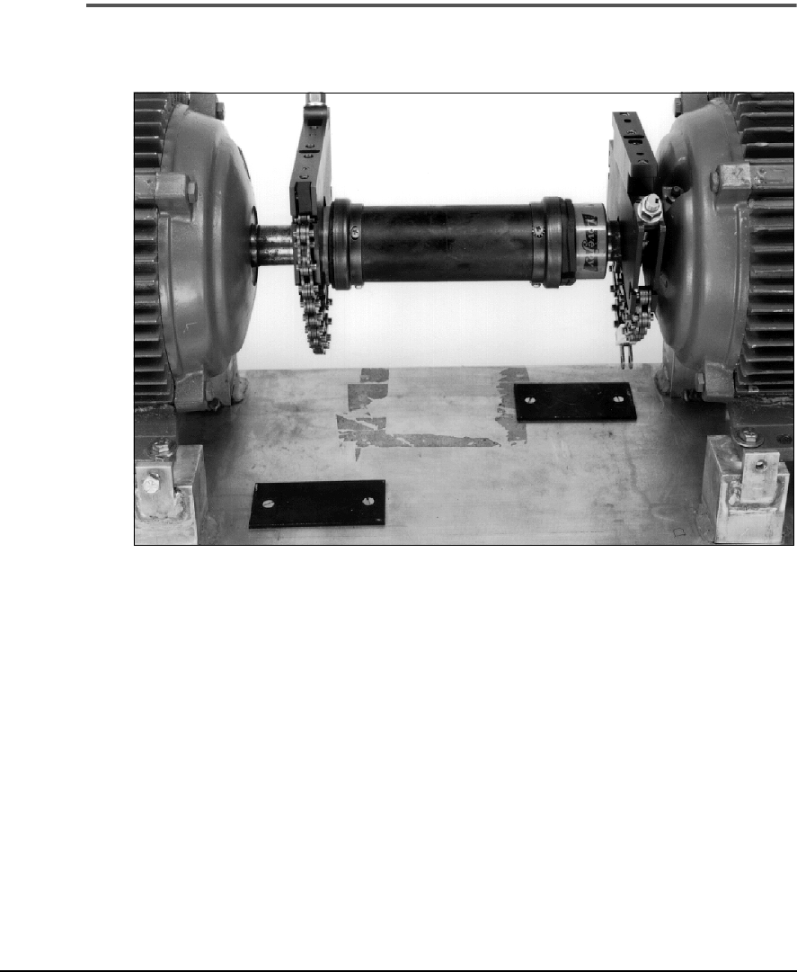
4-44 Setting Up and Using Laser Alignment Fixtures
The gridlines on the front panel should assist you in determining the
approximate movement(s) needed to rough the machines in. Gridline
spacing is 0.3 inches (7.5 mm). The following table shows recommended
moves based upon the gross movement of the laser beam on the sensor
head. Gross movements are discussed in vertical terms for simplicity.
Remember, you are seeing the extended centerline of both machines (see
figure below).
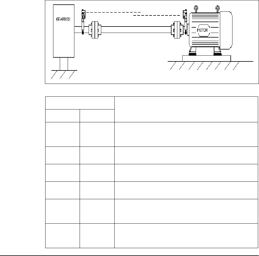
3
Gross Movement
Recommended Machine Move
at Gearbox at Motor
Small Large,
down
Angular & Offset – add shims under the inboard
Gearbox feet or remove shims from the outboard
Gearbox feet.
Large,
down
Small Angular & Offset – add shims under the inboard Motor
feet or remove shims from the outboard Motor feet.
Large, up Large,
down
Offset – add shims to all feet of the Gearbox or remove
shims from all feet of the Motor.
Large,
down
Large, up Offset – add shims to all feet of the Motor or remove
shims from all feet of the Gearbox.
Large, up Large, up Angular – add shims under the outboard feet of both
machines or remove shims from the inboard feet of both
machines.
Large down Large down Angular – remove shims from the outboard feet of both
machines or add shims under the inboard feet of both
machines.

4-45
Attaching the Fixtures
Note
There will, of course, be combinations of the movements
shown in the previous table. However, these recommendations
should provide some general guidelines.
Partial Sweep Rough Alignment
In this method, you must use the fixtures and set the analyzer to Manual
Sweep or Auto Sweep mode. Either method can provide an effective target
area much larger than the 20 mm x 20 mm surface area. If the fixtures can
be rotated and both beams remain on target
greater than 90°
(recom-
mended)
of the sweep, the analyzer can produce an alignment solution from
the data taken. Data gathered from the portion of sweep that laser beams
were off target is rejected. For more information about sweep data collec-
tion modes, see Chapter 6, “Acquiring Alignment Data.”
Note
This procedure will also work when using the Dual Pass mode.

4-46 Setting Up and Using Laser Alignment Fixtures
Introduction to Special Applications
This section covers using additional mounting blocks and mounting on
large diameters (> 8 inches). Normally, additional blocks are used to
achieve greater coupling clearance however, in some cases, you may find
that one (or both) of the mounting blocks must be installed on the coupling
itself. For larger diameter shafts (or mounting on a coupling), additional
lengths of chain may also be needed to mount the base.
4-47
Using Additional Mounting Blocks
Using Additional Mounting Blocks
Mounting a 1-inch Block
This photograph shows a 1-inch block being mounted and tightened onto
the mounting block itself.
Note
CSI recommends that you tighten all vertical mounting block
cap screws to 50 in-lbs (without lubrication).
4-48 Setting Up and Using Laser Alignment Fixtures
Adding a 2-inch Block
This is a picture of a 2-inch block being attached on top of the 1-inch block
(the blocks can be stacked in either order).
4-49
Using Additional Mounting Blocks
This shows the complete 3-inch extension setup. The following table lists
which blocks are to be used for the various vertical extension ranges.
For Vertical Extension
Length (inches) Use These Block(s)
(inches)
00
11
22
3 1, 2
4-50 Setting Up and Using Laser Alignment Fixtures
Mounting One Bracket on a Coupling
If at all possible, CSI recommends that you mount the brackets on the
shafts. However, this is not always possible. Occasionally, you may have to
mount the bracket on a coupling.
This view shows brackets being mounted to the shaft on one side and the
coupling on the other. In order to do this, you may have to use a vertical
extension block(s). In the example shown above, a 1-inch extension block
is being used on the right side; no block is used on the left (coupling) side.

4-51
Using Additional Mounting Blocks
Mounting on Shafts (or Couplings) > 8-inch Diameter
Although the mounting base itself can be used on shaft diameters up to 26
inches (660 mm), additional section(s) of chain must be used for applica-
tions greater than 8 inches (203 mm) in diameter. CSI sells extension
lengths in two feet chain increments (part number D22773). In addition to
the chain itself, extension kits include a clevis pin and a hair pin.
Refer to the following table to determine chains needed with various shaft
diameters.
For Shaft Diameters
Inches (mm) Use These Chain Lengths
Less than 8 (203) Standard Chain Length
8 - 15
1
/
2
(203 – 394) Standard Chain Length +
1 Optional Length
15
1
/
2
– 23
(394 – 584) Standard Chain Length +
2 Optional Lengths
23 – 26
(584 – 660) Standard Chain Length +
3 Optional Lengths

4-52 Setting Up and Using Laser Alignment Fixtures