Computime AAHZT01 Digital ZigBee Thermostat User Manual
Computime Limited Digital ZigBee Thermostat
User Manual
Hardware Requirement Specification
(HRS)
Orion Energy Management Doc.No: 61 8003 011 Valid from
Revision
P5
Approved by: Date:
Orion Energy Management
61 8003 011
HARDWARE REQUIREMENT
SPECIFICATION
HRS

Hardware Requirement Specification
(HRS)
Orion Energy Management Doc.No: 61 8003 011 Valid from
Revision
P7
Author(s): Jan Elfstrom Page 2/25
CONFIDENTIAL ©TIMELOX AB
TABLE OF CONTENTS
TABLE OF CONTENTS.................................................................................................................2
1 DOCUMENT HISTORY..........................................................................................................4
2 INTRODUCTION.....................................................................................................................5
2.1 PROJECT NAME....................................................................................................................5
2.2 PROJECT NUMBER................................................................................................................5
3 REFERENCES ..........................................................................................................................5
4 DEFINITIONS...........................................................................................................................5
5 GENERAL REQUIREMENTS ...............................................................................................5
5.1 USER INTERFACE .................................................................................................................5
5.1.1 Introduction .....................................................................................................................5
5.1.2 Housing............................................................................................................................6
5.1.3 Display.............................................................................................................................7
5.1.4 User Controls ..................................................................................................................7
5.1.5 Electrical interface levels................................................................................................8
5.1.6 Module Communications Interface .................................................................................8
5.1.7 Service Interface..............................................................................................................8
5.1.8 Power supply ...................................................................................................................9
5.1.9 Temperature sensor.........................................................................................................9
5.1.10 Firmware ...................................................................................................................10
5.2 THERMOSTAT CONTROLLER..............................................................................................10
5.2.1 Introduction ...................................................................................................................10
5.2.2 Housing..........................................................................................................................11
5.2.3 Electrical interfaces.......................................................................................................11
5.2.4 I/O Connector................................................................................................................11
5.2.5 Module Communications Interface ...............................................................................12
5.2.6 Power supply .................................................................................................................14
5.2.7 Firmware .......................................................................................................................14
5.2.8 Parameters - CT The following parameters in NV memory is to control the TC. These
values are to be filled in by AAH and used by Computime. ......................................................14
5.2.9 Parameters - AAH .........................................................................................................16
5.2.10 Audit Trail .................................................................................................................16
5.2.11 HVAC Control Chart – Standard Control.................................................................16
5.2.12 Real Time Clock (RTC) .............................................................................................17
5.2.13 Counters ....................................................................................................................17
5.3 MOTION DETECTOR ...........................................................................................................18
5.3.1 Introduction ...................................................................................................................18
5.3.2 Housing..........................................................................................................................19
5.3.3 PIR Detector..................................................................................................................19
5.4 RF DEVICE.........................................................................................................................21
5.4.1 RF Device for User Interface (Phase 2)........................................................................21
5.4.2 RF Device for Motion Detector.....................................................................................21
5.4.3 RF Device for Thermostat Controller ...........................................................................21

Hardware Requirement Specification
(HRS)
Orion Energy Management Doc.No: 61 8003 011 Valid from
Revision
P7
Author(s): Jan Elfstrom Page 3/25
CONFIDENTIAL ©TIMELOX AB
5.5 THERMOSTAT CONTROLLER EXPANDER ...........................................................................21
5.5.1 Introduction ...................................................................................................................21
5.5.2 Housing..........................................................................................................................21
5.5.3 Connectors and interfaces.............................................................................................21
5.5.4 Housing..........................................................................................................................22
6 FIRMWARE REQUIREMENTS ..........................................................................................22
6.1 DESIGN...............................................................................................................................22
6.1.1 Firmware .......................................................................................................................22
7 ELECTRICAL REQUIREMENTS.......................................................................................22
8 MECHANICAL REQUIREMENTS.....................................................................................22
8.1 AESTHETIC DESIGN............................................................................................................22
8.2 FUNCTIONAL DESIGN .........................................................................................................23
9 SOFTWARE REQUIREMENTS ..........................................................................................23
10 ENVIRONMENTAL REQUIREMENTS.............................................................................23
10.1 TEMPERATURES .................................................................................................................23
10.1.1 Storage temperature ..................................................................................................23
10.1.2 Operating temperature ..............................................................................................23
10.2 HUMIDITY ..........................................................................................................................23
10.2.1 Storage humidity........................................................................................................23
10.2.2 Operating humidity....................................................................................................23
10.3 PROTECTION ......................................................................................................................23
10.3.1 User Interface............................................................................................................24
10.3.2 Motion Detector.........................................................................................................24
10.3.3 Thermostat Controller...............................................................................................24
10.4 LIFE CYCLE REQUIREMENT ................................................................................................24
10.4.1 User Interface............................................................................................................24
10.4.2 Motion Detector.........................................................................................................24
10.4.3 Thermostat controller................................................................................................24
10.5 WARRANTIES .....................................................................................................................24
11 SAFETY REQUIREMENTS .................................................................................................24
11.1 FCC ...................................................................................................................................25
11.2 CE......................................................................................................................................25
12 STANDARDS...........................................................................................................................25
12.1 WEEE................................................................................................................................25
12.2 ROHS.................................................................................................................................25
13 DOCUMENTATION ..............................................................................................................25
13.1 TECHNICAL DESCRIPTION..................................................................................................25
13.1.1 Mechanical design.....................................................................................................25
13.1.2 Documentation ..........................................................................................................25
13.1.3 Firmware design........................................................................................................25
Hardware Requirement Specification
(HRS)
Orion Energy Management Doc.No: 61 8003 011 Valid from
Revision
P7
Author(s): Jan Elfstrom Page 4/25
CONFIDENTIAL ©TIMELOX AB
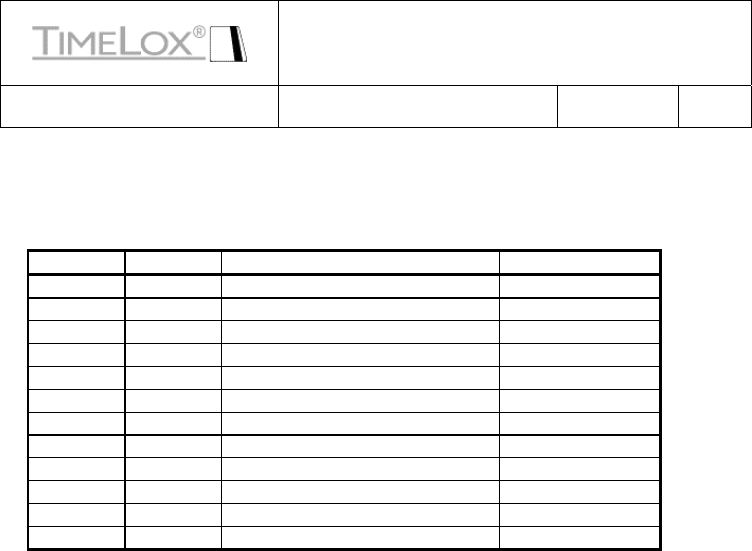
1 DOCUMENT HISTORY
Revision Date Description Author
P1 2009-01-26 Created Jan Elfström
P2 2009-02-12 Computime review Jan Elfström
P3 2009-03-05 Adjustments, Counters added Jan Elfström
P4 2009-03-13 Design Review Jan Elfström
P5 2009-04-28 Adjustments, Parameters Jan Elfström
P6 2009-11-20 Adjustments, parameters Gordon Qian
P7 2010-07-28 Adjustments, parameters Gordon Qian

Hardware Requirement Specification
(HRS)
Orion Energy Management Doc.No: 61 8003 011 Valid from
Revision
P7
Author(s): Jan Elfstrom Page 5/25
CONFIDENTIAL ©TIMELOX AB
2 INTRODUCTION
The purpose of this document is to describe the product requirements in the Orion Energy
Management project.
2.1 Project Name
Orion Energy Management
2.2 Project Number
8003
3 REFERENCES
The following documents are referenced in this document:
61 8003 001 – Orion Project Requirement Specification
61 1100 032-18 - D-032 KOMMUNIKATIONSPROTOKOLL English
Orion Requirement Spec
Aesthetic Design – Bressler Group
4 DEFINITIONS
The following abbreviations are used in this document:
PRS Product Requirement Specification (This document)
MK Market Requirement Specification
TBD To Be Decided
NA Not Applicable
AAH ASSA ABLOY Hospitality
MCU Micro Controller Unit
BDM Background Debug Module
5 GENERAL REQUIREMENTS
The assumption made for the rest of this document is that a third party will supply the actual
hardware and partly FW used for this project. The exception is the use of the RF device described
later where the device supplied by ASSA ABLOY Hospitality shall be used.
It is also assumed the reader is familiar with the document “Orion Project Requirement
Specification” and “Orion Requirement Spec”.
MCU:s shall be of the Freescale HCS08 family (other types/brands can be used after approval).
5.1 User Interface
5.1.1 Introduction
The User Interface (UI) is the device where a local (in-room) user can check status of the energy
management system (e.g. set temperature, fan-speed) and control certain functions (e.g. alter set
temperature).
Hardware Requirement Specification
(HRS)
Orion Energy Management Doc.No: 61 8003 011 Valid from
Revision
P7
Author(s): Jan Elfstrom Page 6/25
CONFIDENTIAL ©TIMELOX AB
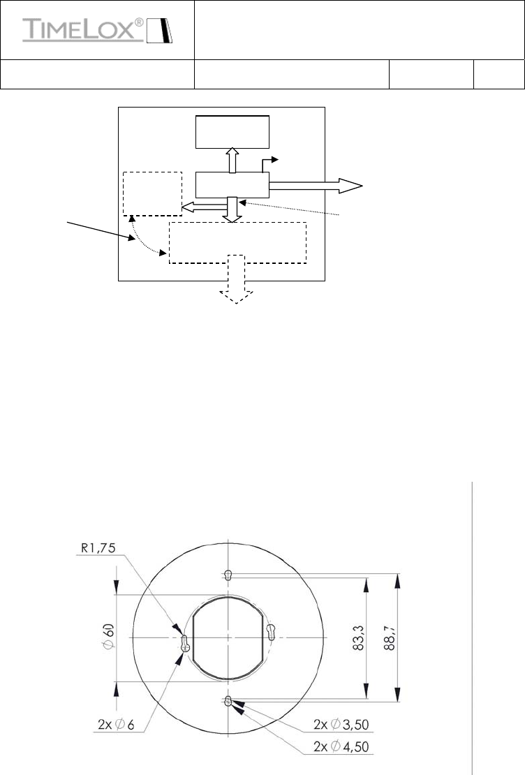
Possible configuration of the UI
5.1.2 Housing
5.1.2.1 The mechanical design shall be based on the information received from
Bressler.
(Computime to give best estimate of box size after receiving 3D-model)
5.1.2.2 The mounting holes shall be such that they fit the following screw-patterns:
• Single gang junction box
• European single gang box
Example of hole pattern
UI MCU
Display +
Keys
5
.1.7
Se
rvi
ce
-
Co
nn
ec
t
o
r
Temp-
Sensor
Optional
Battery +
Radio
Thermostat Controller (TC)
+ Radio
5.2.4 I/O-
Connector
5.1.6 Module Communications Interface
N.B. Shall not be
mounted together!

Hardware Requirement Specification
(HRS)
Orion Energy Management Doc.No: 61 8003 011 Valid from
Revision
P7
Author(s): Jan Elfstrom Page 7/25
CONFIDENTIAL ©TIMELOX AB
5.1.2.3 The mounting holes shall be of the key-hole type or similar to allow easy
mount/dismount and positioning of the UI
5.1.2.4 The UI shall be designed to allow mounting of the TC or a battery pack
(3xAA) with a RF-device
5.1.2.5 The battery pack shall be easily accessed
5.1.2.6 The battery pack can be the standard AAH 3xAA cassette with cable (Art
No 4816065 + 4809763)
5.1.3 Display
5.1.3.1 The display shall have a visible size as defined by the industrial design from
Bressler Group. (Computime to advice on the actual dimension)
5.1.3.2 The display graphics and symbols shall be designed according to the
information received from Bressler.
5.1.3.3 The following symbols shall be possible to control:
• Fan-speed indicator (Three steps)
• Service Indicator (Wrench)
• Error Indicator (E)
• Farenheit/Celsius Indicator
• Locked Indicator (pad-lock symbol)
• Cooling/Heating Indicator (Snow-star/flame)
• Temperature read-out (two digits, seven segments)
• Battery indicator (Battery low only)
• Auto Indicator (AUTO) (This indicator can be an alpha numeric field)
5.1.3.4 The display technology shall be of the transflective LCD type.
5.1.3.5 Viewing angle
:
55o @12:00 clock direction
5.1.3.6 Backlighter shall be LED
5.1.3.7 Backlighter shall be possible to control (on/off)
5.1.3.8 Backlighter colour is to be white
5.1.4 User Controls
5.1.4.1 The following user controls shall be used
• On/Off button (Controls only EMS functions, not system power)
• Fan Control button (Switch steps through settings)

Hardware Requirement Specification
(HRS)
Orion Energy Management Doc.No: 61 8003 011 Valid from
Revision
P7
Author(s): Jan Elfstrom Page 8/25
CONFIDENTIAL ©TIMELOX AB
• “Up” button
• “Down” button
• Celsius/Fahrenheit button (Toggle function)
5.1.5 Electrical interface levels
5.1.5.1 The UI I/O shall tolerate voltages in the range 3 – 5VDC
5.1.5.2 The UI output voltage-levels shall be in the range 0 - 5VDC
5.1.5.3 Logical high level shall be minimum 3.0V
5.1.5.4 Logical low level shall be maximum 0.5V
5.1.6 Module Communications Interface
5.1.6.1 The communication to/from the UI shall be with asynchronous full duplex
communication (38400 8N1)
5.1.6.2 The communication protocol shall be based on the specification D-032
5.1.6.3 The electrical interface between the UI and other modules shall be over a 6-
pin JST PHR-6, tin plated or equivalent connector
5.1.6.4 The wire harness for the PHR-6 connector shall be 50 mm long
5.1.6.5 The following pin-out shall be used:
1- VCC
2- GND
3- Activate (UI)
4- Wakeup (Module)
5- RxD (From UI)
6- TxD (To UI)
5.1.7 Service Interface
5.1.7.1 The UI shall have a service connector of the type 3.5mm stereo-jack
5.1.7.2 The Service connector shall be protected against ESD (8KV for air
discharge )
5.1.7.3 The following signals shall be used
1- Power input 3.5 – 10VDC (tip)
2- Serial communication (middle)
3- GND (inner)

Hardware Requirement Specification
(HRS)
Orion Energy Management Doc.No: 61 8003 011 Valid from
Revision
P7
Author(s): Jan Elfstrom Page 9/25
CONFIDENTIAL ©TIMELOX AB
5.1.7.4 The serial communication to/from the service interface shall be with
asynchronous half duplex communication (38400 8N1)
5.1.7.5 The serial communication shall be initiated with an “ACK” (0x06) from the
UI when external power is detected at the service connector
5.1.7.6 The initiation shall be complete in the interval 50 - 200ms after external
power is detected
5.1.7.7 The service device shall answer with “ACK” in the interval 0 - 200ms after
the “ACK” is transmitted
5.1.7.8 The UI shall accept a command-set implemented by AAH
5.1.7.9 The UI shall handle communication through the service connector to the
thermostat or RF module over the module communications interface
5.1.7.10 The service-connector shall be placed at the bottom of the UI (Not visible
from front)
5.1.7.11 The service-connector shall be placed such that it is easily accessible
5.1.7.12 The service-connector shall tolerate voltages in the range 3 – 10VDC
5.1.7.13 Logical high level shall be minimum 3.0V
5.1.7.14 Logical low level shall be maximum 0.5V
5.1.8 Power supply
5.1.8.1 The UI shall be possible to run off three AA 1.5V alkaline cells (3.2 – 4.5V)
5.1.8.2 The UI shall be possible to run on an external fixed +3.2 - +5V supply
(Supplied through the Module Communications Interface) from the TC
5.1.8.3 The UI shall have a maximum average current consumption of 4mA @4.5V
(not including other modules)
5.1.8.4 The UI shall have a maximum current consumption of 150mA @+4.5V (not
including other modules)
5.1.8.5 The supplied voltage shall be possible to read with a minimum resolution of
0.1V
5.1.9 Temperature sensor
Hardware Requirement Specification
(HRS)
Orion Energy Management Doc.No: 61 8003 011 Valid from
Revision
P7
Author(s): Jan Elfstrom Page 10/25
CONFIDENTIAL ©TIMELOX AB
5.1.9.1 The UI shall have the means of measuring temperature
5.1.9.2 The temperature value shall have a tolerance of +/-0.5°C including drift
5.1.9.3 The temperature sensor shall have a calibrated value of +/-1°C @22°C
5.1.10 Firmware
5.1.10.1 The UI firmware (FW) shall be possible to upgrade through the service
connector using the AAH standard bootloader protocol
5.1.10.2 A callback function called when a key-press or other event occur shall be
implemented for AAH use.
5.1.10.3 A control structure shall be developed for accessing and controlling
resources in the UI (e.g. displayed symbols, temperature display etc)
5.1.10.4 A data structure with information of pressed keys, temperature reading etc
shall be developed
5.2 Thermostat Controller
5.2.1 Introduction
The Thermostat Controller (TC) is the device where the actual logic for energy management is
implemented. It is also the device controlling the other in-room devices connected to the EMS
system and can be connected to a central control system.
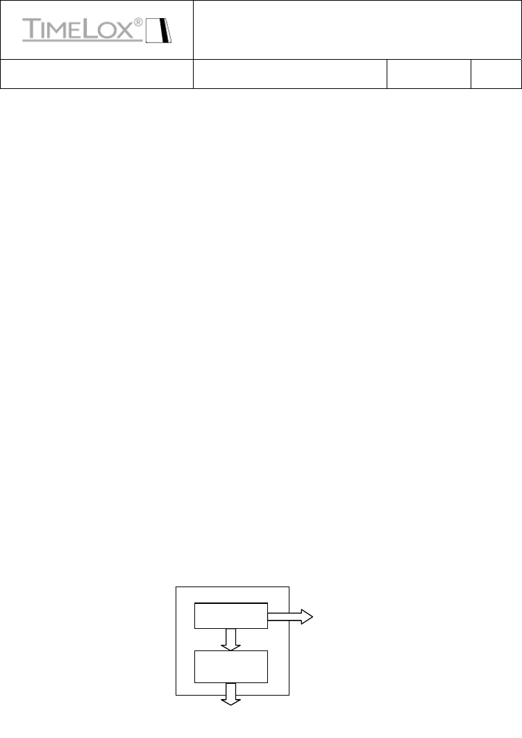
Possible configuration of the TC
TC MCU
5
.2.
5
M
odu
l
e
Co
mm
u
ni
ca
ti
o
n
s
Int
e
rf
ace
5.2.4 I/O-
Connector
Signal
Conditioning

Hardware Requirement Specification
(HRS)
Orion Energy Management Doc.No: 61 8003 011 Valid from
Revision
P7
Author(s): Jan Elfstrom Page 11/25
CONFIDENTIAL ©TIMELOX AB
5.2.2 Housing
5.2.2.1 The TC shall be designed to fit the housing of the UI and the Thermostat
Controller Expander device
5.2.3 Electrical interfaces
5.2.3.1 The electrical interface between the TC and other modules shall be over a
6-pin, tin plated connector suitable for a JST PHR-6 connector plug
5.2.3.2 The TC module I/O shall tolerate voltages in the range 3 – 5VDC
5.2.3.3 The TC module I/O output voltage-levels shall be in the range 0 - 5VDC
5.2.3.4 Logical high level shall be minimum 3.0V
5.2.3.5 Logical low level shall be maximum 0.3V
5.2.3.6 A connector for the MCU BDM shall be included in the design
5.2.4 I/O Connector
5.2.4.1 The TC shall have a I/O connector for controlling external systems, e.g. air-
handlers
5.2.4.2 The TC module I/O shall tolerate voltages up to 30VDC
5.2.4.3 Logical high level shall be minimum 5.0V
5.2.4.4 Logical low level shall be maximum 0.5V
5.2.4.5 The I/O connector shall be of the type Molex KK 2695 2.54mm or
equivalent
5.2.4.6 The I/O connector shall have the following pin-out:
1- W/W2 – Heating (Output)
2- Y/W1 – Cooling / Compressor (Output)
3- G1 – Fan 1 (Output)
4- G2 – Fan 2 (Output)
5- G3 – Fan 3 (Output)
6- RV – Reversing valve (Output)
7- Emergency Heating - Outputs
8- Door Switch – Interior (Intput)
9- Door Switch – Exterior (Intput)
10- Extra Input1 (Intput)
11- Ground
Hardware Requirement Specification
(HRS)
Orion Energy Management Doc.No: 61 8003 011 Valid from
Revision
P7
Author(s): Jan Elfstrom Page 12/25
CONFIDENTIAL
©TIMELOX AB
12- Power out for External Switch
13- Power Supply Common for Thermostat
14- Power Supply for thermostat
5.2.4.7 The I/O connector shall control outputs through potential free switches (e.g.
relay)
5.2.4.8 The I/O connector shall have the same potential for all I/O
5.2.4.9 The TC shall be delivered with a wire-harness fitting the I/O connector with
a wire length of 150mm +/-10mm. (Colors as defined below)
1- W/W2 – White)
2- Y/W1 – Yellow
3- G1 – Green
4- G2 – Orange
5- G3 – Dark Blue
6- RV – Violet
7- Emergency Heating - Brown
8- Door Switch –Interior – Gray (not hard requirement)
9- Door Switch – Exterior – Orange/Blue (not hard requirement)
10- Extra Input1 (Intput) – Pink (not hard requirement)
11- ground –Black
12- Power out for External Switch – White/Black
13- Power Supply Common for Thermostat – Light Blue
14- Power Supply for thermostat – Red
5.2.4.10 The I/O Connector shall be secured with a friction lock or similar
5.2.4.11 Wires with an area of AWG 22 shall be used
5.2.4.12 A visible label shall be included indicating signals in I/O connector
5.2.5 Module Communications Interface
5.2.5.1 The communication to/from the TC shall be with asynchronous full duplex
communication (38400 8N1)
5.2.5.2 The TC shall accept a command-set implemented by AAH
5.2.5.3 The following pin-out shall be used:
1- VCC (Power out to UI)
2- GND
3- Activate (UI)
4- Wakeup (TC)
5- RxD (To TC)

Hardware Requirement Specification
(HRS)
Orion Energy Management Doc.No: 61 8003 011 Valid from
Revision
P7
Author(s): Jan Elfstrom Page 13/25
CONFIDENTIAL ©TIMELOX AB
6- TxD (From TC)
5.2.5.4 The TC firmware (FW) shall be possible to upgrade

Hardware Requirement Specification
(HRS)
Orion Energy Management Doc.No: 61 8003 011 Valid from
Revision
P7
Author(s): Jan Elfstrom Page 14/25
CONFIDENTIAL ©TIMELOX AB
5.2.5.5 There shall be a minimum of 32kByte Flash and 500 byte RAM available
for AAH use
5.2.6 Power supply
5.2.6.1 The TC shall be possible to run on a fixed 12 – 30VAC/DC supply
5.2.6.2 The TC shall have a maximum current consumption of 150mA @24VDC
TBD (not including other modules)
5.2.6.3 The power supply inputs shall be protected against reversed polarity
5.2.6.4 The power supply inputs shall have protection against short circuit (non-
permanent, no change of components)
5.2.7 Firmware
5.2.7.1 The TC firmware (FW) shall be possible to upgrade through the 6-pin
Module Communications Connector using the AAH standard bootloader protocol
5.2.7.2 Test-mode
When the TC is put in test-mode by the service-tool, all outputs shall be disabled. All
output and input-states shall be possible to observe on the test-tool.
5.2.7.3 A callback function called 1/s shall be implemented for AAH use.
5.2.7.4 A control structure shall be developed for accessing and controlling
resources in the TC, including external inputs.
5.2.7.5 The responsibility for the actual implementation of different functionality is
AAH
5.2.8 Parameters - CT
The following parameters in NV memory is to control the TC. These values are to be
filled in by AAH and used by Computime.
5.2.8.1 ActualTemperature – The reported temperature (external sensor or UI
sensor)
5.2.8.2 ManualOverrideBitField – Controls for service purposes
• Fan-on (bit7) – Turn on the fan
• Fan-speed (bit6-5) – Fan speed, 0 - 2
• Heat (bit4) – Turn on heating
• Cool (bit3) – Turn on cooling
• RFU (bit2-0)

Hardware Requirement Specification
(HRS)
Orion Energy Management Doc.No: 61 8003 011 Valid from
Revision
P7
Author(s): Jan Elfstrom Page 15/25
CONFIDENTIAL ©TIMELOX AB
5.2.8.3 ControlBitfield1 – Controls for TC operation
• FanMan (bit7) – Manual Speed (1), Auto (0)
• FanSat (bit6) – Run when satisfied (1), Stop when satisfied (0)
• SetbackEnable (bit5) – Use setback set-point
• Thermostat enable (bit4) – 1: Turn on thermostat
• MaxFan (bit3-2) – Max allowed fan-speed (if less than three steps)
• Fan-speed (bit1-0) – Fan speed 0-2, valid if FanMan = 1
5.2.8.4 ControlBitfield2 – Controls for TC Service
• ServiceEnable (bit7) (Disables all outputs for manual control)
• BacklighterEnable (bit6) (For test of LED)
• REL6Enable (bit5)
• REL5Enable (bit4)
• REL4Enable (bit3)
• REL3Enable (bit2)
• REL2Enable (bit1)
• REL1Enable (bit0)
5.2.8.5 ActualSetpoint – The TC setpoint 0-99°F
5.2.8.6 ActualDeadbands
• Heat/Cool switching (bit7,6,5,4) 2-4°F
• Thermostat deadband (bit3,2,1,0) 1-3°F
Hardware Requirement Specification
(HRS)
Orion Energy Management Doc.No: 61 8003 011 Valid from
Revision
P7
Author(s): Jan Elfstrom Page 16/25
CONFIDENTIAL ©TIMELOX AB
5.2.8.7 ActualSetbackUpper - Setpoint in setback cooling 0-99°F
5.2.8.8 ActualSetbackLower - Setpoint in setback heating 0-99°F
5.2.9 Parameters - AAH
5.2.9.1 AAH Parameters – 84 bytes of NV memory storage shall be reserved for
AAH use
5.2.9.2 AAH RFU Parameters - 20bytes
5.2.10 Audit Trail
5.2.10.1 An audit trail of 100 entries shall be included
5.2.10.2 The audit trail shall be designed in a round-robin fashion such that the
oldest event gets overwritten first
5.2.10.3 The audit trail shall be stored in a non volatile memory, e.g. external
E2PROM
5.2.10.4 Each event shall be ten bytes long
5.2.10.5 Alarms e.g. battery-level shall set a flag that can be reset by EMS-system or
service terminal
5.2.11 HVAC Control Chart – Standard Control
Temperature difference from
Guest Setting Active Outputs
+4 Y, G3 (Cooling)
+3 Y, G2 (Cooling)
+2 Y, G1 (Cooling)
+1 None
0 None
-1 None
-2 W, G1 (Heating)
-3 W, G2 (Heating)
-4 W, G3 (Heating)

Hardware Requirement Specification
(HRS)
Orion Energy Management Doc.No: 61 8003 011 Valid from
Revision
P7
Author(s): Jan Elfstrom Page 17/25
CONFIDENTIAL ©TIMELOX AB
5.2.12 Real Time Clock (RTC)
5.2.12.1 A RTC shall be designed based on a standard low power 32kHz crystal
5.2.12.2 The RTC function can be an internal MCU timer clocked by the low power
crystal
5.2.12.3 Maximum time deviation over a year shall be +/-15 minutes
5.2.12.4 The minimum resolution shall be one minute
5.2.12.5 The real time shall be an incremental number with the length of four bytes
5.2.12.6 The start time for the real-time count (0) shall be 1996-07-20 00:00
5.2.12.7 No support for day-light saving shall exist
5.2.13 Counters
5.2.13.1 Counter for total HVAC run time [32-bit value, minute resolution]
5.2.13.2 Counter for HVAC run time maintaining the guest set-point (starts when
guest set-point is first reached from set-back) [32-bit value, minute resolution]
5.2.13.3 Counter for total HVAC run time in unoccupied and unsold set-back
including recovery time from setback to set point [32-bit value, minute resolution]
5.2.13.4 Counter for total occupancy time [32-bit value, minute resolution]
5.2.13.5 Three maintenance run time parameters [32-bit value, minute resolution]
• tlmMaintenanceCounter1
• tlmMaintenanceCounter2
• tlmMaintenanceCounter3

Hardware Requirement Specification
(HRS)
Orion Energy Management Doc.No: 61 8003 011 Valid from
Revision
P7
Author(s): Jan Elfstrom Page 18/25
CONFIDENTIAL ©TIMELOX AB
5.2.13.6 When one of the three maintenance parameter values match the total
HVAC run time counter, a notification shall be sent to the server indicating which of the
parameters that triggered the event.
5.2.13.7 The three maintenance run time parameters shall be possible to update
using the EMS GUI or the commissioning tool
5.2.13.8 The maintenance run time parameters shall be updated with an offset added
to the total HVAC run time counter
5.2.13.9 The counters and maintenance parameters shall be stored in non-volatile
memory
5.3 Motion Detector
5.3.1 Introduction
The Motion Detector (MD) is used to detect and report movement in the room. It can also be used
in suite configurations. It is a battery operated device.
Hardware Requirement Specification
(HRS)
Orion Energy Management Doc.No: 61 8003 011 Valid from
Revision
P7
Author(s): Jan Elfstrom Page 19/25
CONFIDENTIAL ©TIMELOX AB
5.3.2 Housing
5.3.2.1 The mechanical design shall be based on the industrial design from
Bressler Group and modified when suitable lens design found)
5.3.2.2 The mounting holes shall be of the key-hole type or similar to allow easy
mount/dismount and positioning of the MD
5.3.2.3 The MD shall be designed to allow mounting of a RF-device
5.3.2.4 The battery pack shall be easily accessed
5.3.2.5 The battery pack can be the standard AAH 3xAA cassette with cable (Art
No 4816065 + 4809763)
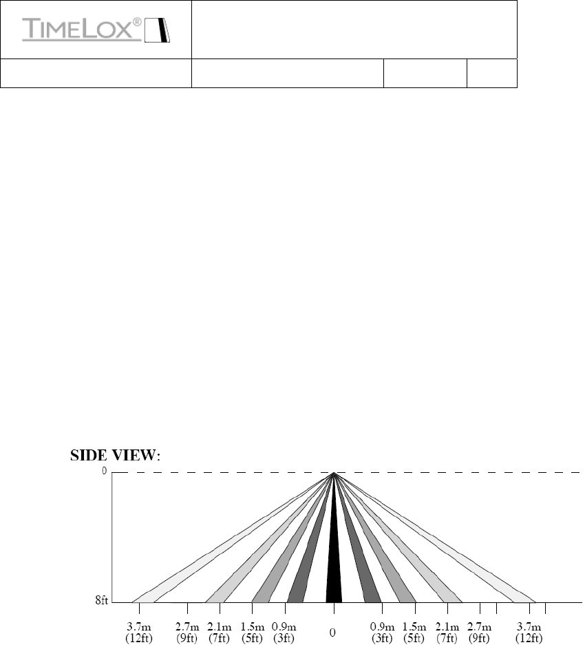
5.3.3 PIR Detector
5.3.3.1 The PIR Detector (PD) shall be powered by three AA alkaline batteries
5.3.3.2 The PIR Detector (PD) Sense range and angle
Hardware Requirement Specification
(HRS)
Orion Energy Management Doc.No: 61 8003 011 Valid from
Revision
P7
Author(s): Jan Elfstrom Page 20/25
CONFIDENTIAL ©TIMELOX AB
5.3.3.3 The PD shall have a maximum current consumption of 15mA @4.5VDC
TBD (not including other modules)
5.3.3.4 The PD shall have a maximum average current consumption of 150uA
@4.5V when PIR is on and 25uA @4.5V when PIR is OFF (not including other modules)
5.3.3.5 The PD shall have a service connector of the type 3.5mm stereo-jack
5.3.3.6 The Service connector shall be protected against ESD (8KVair discharge )
5.3.3.7 The following signals shall be used (J2):
1- Power input 3.5 – 10VDC (tip)
2- Serial communication (middle)
3- GND (inner)
5.3.3.8 The electrical interface between the PD and other modules shall be over a
6-pin JST PHR-6, tin plated or equivalent connector
5.3.3.9 The wire harness for the PHR-6 connector shall be 50 mm long
5.3.3.10 The following pin-out shall be used (J1):
1- VCC (Battery voltage to RF-device)
2- GND
3- Activate
4- Wakeup
5- RxD (Serial connection to service connector)
6- TxD (Not used)
5.3.3.11 The following connection shall be used (including ESD protection etc):
1- Power (J1:1 – J2:1)
2- GND (J1:2 – J2:3)
3- Serial data (J1:5 – J2:2) (N.B. J1:1-2 might need to be externally connected)
Hardware Requirement Specification
(HRS)
Orion Energy Management Doc.No: 61 8003 011 Valid from
Revision
P7
Author(s): Jan Elfstrom Page 21/25
CONFIDENTIAL ©TIMELOX AB
5.4 RF Device
5.4.1 RF Device for User Interface (Phase 2)
5.4.1.1 The RF device 68 3081 055 or similar supplied by AAH shall be used
5.4.1.2 The RF device firmware can be special for this application
5.4.2 RF Device for Motion Detector
5.4.2.1 The RF device 68 3081 055 or similar supplied by AAH shall be used
5.4.2.2 The RF device firmware can be special for this application
5.4.3 RF Device for Thermostat Controller
5.4.3.1 The RF device 68 3081 055 or similar supplied by AAH shall be used
5.4.3.2 The RF device firmware can be special for this application
5.5 Thermostat Controller Expander
5.5.1 Introduction
The Thermostat Controller Expander (TCE) is accepting the TC as a piggy back device. This allows
the use of the TC+TCE as a standalone device with the possibility of e.g. external power and more
rugged connections. It will also form a more rugged housing for the TC.
(TCE will be designed for Phase 2 of this project)
5.5.2 Housing
5.5.2.1 TBD
5.5.3 Connectors and interfaces
5.5.3.1 The TCE shall have a service connector of the type 3.5mm stereo-jack
5.5.3.2 The Service connector shall be protected against ESD (8KV for air
discharge )
5.5.3.3 The following signals for the service connector shall be used
1- Power input 3.5 – 10VDC (tip)
2- Serial communication (middle)
3- GND (inner)

Hardware Requirement Specification
(HRS)
Orion Energy Management Doc.No: 61 8003 011 Valid from
Revision
P7
Author(s): Jan Elfstrom Page 22/25
CONFIDENTIAL ©TIMELOX AB
5.5.3.4 The electrical interface between the TCE and the TC shall be over a 6-pin
JST PHR-6, tin plated or equivalent connector
5.5.3.5 The wire harness for the PHR-6 connector shall be TBD mm long
5.5.3.6 The following pin-out for the PHR-6 shall be used:
1- VCC (Power to TCE logic)
2- GND
3- Activate (TBD)
4- Wakeup (TBD)
5- RxD (Serial connection to service connector)
6- TxD (Not used)
7-
5.5.4 Housing
5.5.4.1 TBD
6 FIRMWARE REQUIREMENTS
6.1 Design
6.1.1 Firmware
6.1.1.1 The firmware shall be stored in a non-volatile memory
6.1.1.2 The firmware shall be possible to change in field
6.1.1.3 A boot-loader shall be used for change of firmware through the service-
interface
6.1.1.4 The bootloader shall function according to the AAH standard bootloader
protocol
7 ELECTRICAL REQUIREMENTS
NA
8 MECHANICAL REQUIREMENTS
8.1 Aesthetic design
The overall aesthetic design shall be according to the Bressler guidelines

Hardware Requirement Specification
(HRS)
Orion Energy Management Doc.No: 61 8003 011 Valid from
Revision
P7
Author(s): Jan Elfstrom Page 23/25
CONFIDENTIAL ©TIMELOX AB
8.2 Functional design
The functional design is left open to best fit the production requirements and the aesthetic design
9 SOFTWARE REQUIREMENTS
NA
10 ENVIRONMENTAL REQUIREMENTS
10.1 Temperatures
10.1.1 Storage temperature
10.1.1.1 The storage temperature for all devices shall be -20 - +85°C
10.1.2 Operating temperature
10.1.2.1 The operating temperature for all devices shall be 0 - +45°C
10.2 Humidity
10.2.1 Storage humidity
10.2.1.1 The storage humidity for all devices shall be 10-98%RH non-condensing
10.2.2 Operating humidity
10.2.2.1 The operating humidity for all devices shall be 15-95%RH non-condensing
10.3 Protection
A general test shall be made with each device to find which components that is sensitive to
condensation. Those areas shall then be protected with conformal coating.

Hardware Requirement Specification
(HRS)
Orion Energy Management Doc.No: 61 8003 011 Valid from
Revision
P7
Author(s): Jan Elfstrom Page 24/25
CONFIDENTIAL ©TIMELOX AB
10.3.1 User Interface
10.3.1.1 The device shall meet IP20 classification
10.3.2 Motion Detector
10.3.2.1 The device shall meet IP20 classification
10.3.3 Thermostat Controller
10.3.3.1 The device shall be part of the User Interface and is covered by that
housing
10.4 Life cycle requirement
10.4.1 User Interface
10.4.1.1 The LED backlighter intensity shall not degrade below 50%of the initial
value before 50000 h
10.4.1.2 The switches shall not fail before 20000 cycles
10.4.1.3 The unit except the LED and switches shall have a life cycle of ten years of
normal use
10.4.2 Motion Detector
10.4.2.1 The unit shall have a life cycle of ten years of normal use
10.4.3 Thermostat controller
10.4.3.1 The relays shall not fail before 100000 cycles
10.4.3.2 The unit shall have a life cycle of ten years of normal use
10.5 Warranties
11 SAFETY REQUIREMENTS
Normal safety precautions shall be made to prevent fire etc.

Hardware Requirement Specification
(HRS)
Orion Energy Management Doc.No: 61 8003 011 Valid from
Revision
P7
Author(s): Jan Elfstrom Page 25/25
CONFIDENTIAL ©TIMELOX AB
11.1 FCC
11.2 CE
12 STANDARDS
12.1 WEEE
12.2 RoHS
13 DOCUMENTATION
13.1 Technical Description
13.1.1 Mechanical design
13.1.1.1 The mechanical design shall be fully documented
13.1.1.2 The IGS/STEP format shall be used for exchanging 3D models
13.1.1.3 The DXF format shall be used for exchanging 2D drawings
13.1.1.4 The native Solid Works format can be used for all documentation
13.1.2 Documentation
13.1.2.1 All final documentation shall be in the Timelox defined form and shape
including document numbers
13.1.3 Firmware design
13.1.3.1 All open interfaces shall be fully documented
13.1.3.2 A general functional description shall be delivered
FCC STATEMENT
1. This device complies with Part 15 of the FCC Rules.Operation is subject to the following two conditions:
(1) This device may not cause harmful interference.
(2) This device must accept any interference received, including interference that may cause undesired operation.
2. Changes or modifications not expressly approved by the party responsible for compliance could
void the user's authority to operate the equipment.
RF warning statement:The device has been evaluated to meet general RF exposure requirement.
The device can be used in portable exposure condition without restriction.