Computime CTL2607 ZigBee-Ready RF Transceiver User Manual CTL2607 Product Specifications R1
Computime Ltd. ZigBee-Ready RF Transceiver CTL2607 Product Specifications R1
User manual

Copyright © 2011 Computime Limited. All rights reserved. Rev. 2
ZigBee- Ready SoC RF Transceiver Modules
CTL2607
The reproduction of this datasheet is NOT allowed without approval of Computime Limited. All information and data contained in
this datasheet are subject to change without notice. This publication supersedes and replaces all information previously supplied.
Computime has no responsibility to the consequence of using the information described in this document.

ZigBee- Ready SoC RF Transceiver Modules CTL2607
Copyright © 2011 Computime Limited. All rights reserved. Rev. 2
Page 1
Table of Contents
1. General Description ...................................................................................................................................... 2
2. Applications .................................................................................................................................................. 2
3. Features ....................................................................................................................................................... 2
4. Absolute Maximum Ratings .......................................................................................................................... 3
5. Recommended Operating Conditions .......................................................................................................... 3
6. Electrical Specifications ................................................................................................................................ 4
7. Pin Assignment ............................................................................................................................................. 5
8. Pin Description ............................................................................................................................................. 5
9. Block Diagram .............................................................................................................................................. 7
10. Circuit Description ........................................................................................................................................ 7
11. SIF Module Programming and Debug Interface ........................................................................................... 8
12. Power Management ..................................................................................................................................... 8
13. RF Frequency Detail..................................................................................................................................... 9
14. Antenna Design Considerations ................................................................................................................. 10
15. PCB Layout Recommendations ................................................................................................................. 11
16. Product Approvals ...................................................................................................................................... 12
17. Typical application block ............................................................................................................................ 15
18. Mechanical Dimensions .............................................................................................................................. 15
19. Ordering Information ................................................................................................................................... 17
20. Moisture Sensitivity Level (MSL) ................................................................................................................ 17
21. Document Revision History ........................................................................................................................ 17
ZigBee- Ready SoC RF Transceiver Modules CTL2607
Copyright © 2011 Computime Limited. All rights reserved. Rev. 2
Page 2
1. General Description
The CTL2607 RF Transceiver Modules is compact surface mounted modules specially designed for Ember
ZigBee™ protocol stack for wireless networks, EmberZNet, based on IEEE 802.15.4 standard in the 2.4GHz
world-wide ISM band. The complete module is only 32.4 x 25.4 x 4.1mm .They both integrate a 2.4GHz,
IEEE 802.15.4-compliant transceiver with a 16-bit network processor (XAP2b core) to run EmberZNet. They
contain embedded Flash and integrated RAM for program and data storage. It utilizes the non-intrusive SIF
module for powerful software debugging and programming of the network processor.
The CTL2607 modules are specially designed for ZigBee application. They provide a fast jump start design
for system integrators or electronic designers wishing to use ZigBee wireless technologies. The module
contains qualified RF hardware and enough processor power to run the EmberZNet stack or other ZigBee
network stack (depending on version), making it a powerful platform for building wireless networking
products. ZigBee Coordinators (ZC), ZigBee Routers (ZR), and ZigBee End Devices (ZED) are all supported
and are programmed onto the module together with a custom application. Minimal RF design experience is
need to use CTL2607 modules.
2. Applications
Home
automation &
building control
Home
appliances &
alarms
Monitoring of
remote systems
Lighting
controls
Sensor data
capturing
3. Features
Complete ZigBee-ready module with or without integrated chip antenna
Integrated IEEE 802.15.4 PHY and MAC layer
12MHz XAP2b 16-bit network processor core
Integrated FEM(Front-End Module)
Non-intrusive debug interface (SIF)
SPI interface for communication and controlled by the Host using the EmberZNet Serial Protocol (EZSP)
Internal RC oscillator for timer
16 channels in the 2.4 GHz ISM band
On-chip regulator for 2.7-3.6V operation , three sleep low power modesǂ
-17dBm------20dBm output power, SW controlled
-19+/-1dBm ------ 18+/-1dBm output power, SW controlled
ZigBee- Ready SoC RF Transceiver Modules CTL2607
Copyright © 2011 Computime Limited. All rights reserved. Rev. 2
Page 3
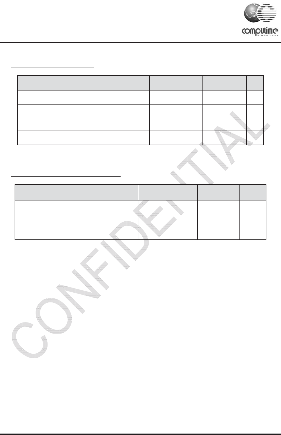
4. Absolute Maximum Ratings
Parameter Test
Conditions
Min. Max. Unit
Regulator voltage (VDD_PADS) - 0.3 3.6 V
Voltage on nSSEL INT, MOSI, MISO, SCLK, nSSEL,
PTI_EN, PTI_DATA, nHOST_INT, SIF_CLK, SIF_MISO,
SIF_MOSI, nSIF_LOAD, SDBG, LINK_ACTIVITY,
nWAKE, nRESET
- 0.3 VDD_PADS+0.3 V
Storage temperature - 40 + 140 °C
Under no circumstances should the absolute maximum ratings given above be violated. Stress exceeding one or more of
the limiting values may cause permanent damage to the device.
5. Recommended Operating Conditions
Parameter Test
Conditions Min. Typ. Max. Unit
Regulator input voltage (VDD_PADS) 2.7 3.6
Temperature range - 40 + 85 °C
ZigBee- Ready SoC RF Transceiver Modules CTL2607
Copyright © 2011 Computime Limited. All rights reserved. Rev. 2
Page 4
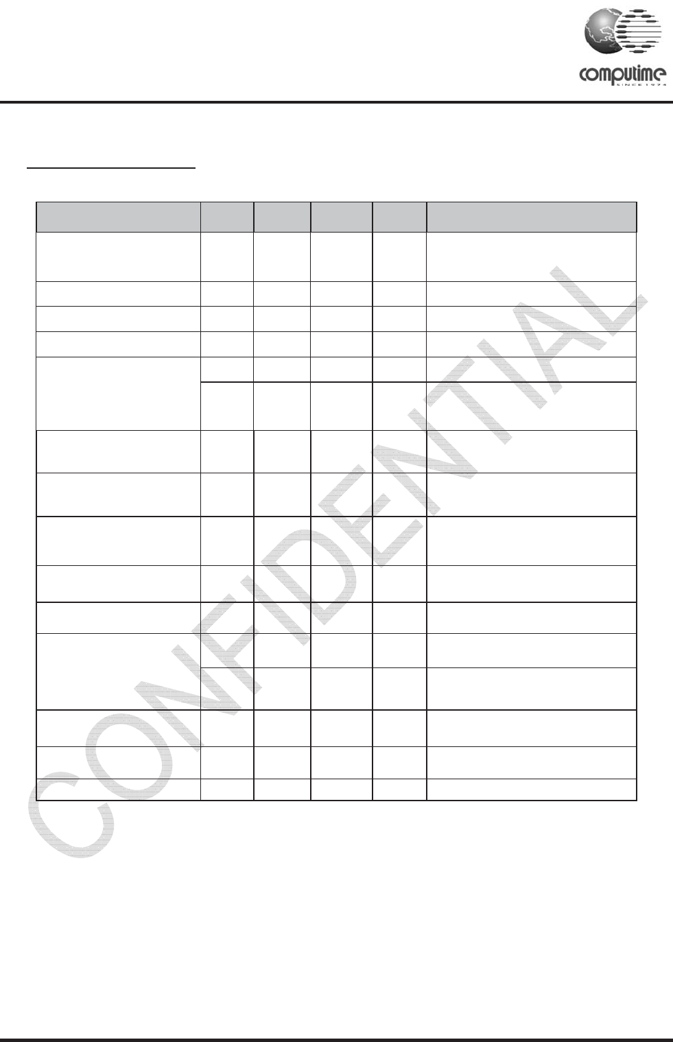
6. Electrical Specifications
T=25ć, VCC = 3.0V, Fo =2450MHZ, if nothing else stated.
Parameter Min Typ. Max Unit Condition / Note
Operating frequency 2.4 2.5 GHz
Programmable in 5MHz steps, 5 MHz
steps for IEEE 802.15.4 compliance
Number of channels 16 For IEEE 802.15.4 compliance
Channel spacing 5 MHz For IEEE 802.15.4 compliance
Input/output impedance 50 Ohm
Frequency stability +/-40 ppm
Transmit power -17 20 dBm Programmable from firmware
Sensitivity -98 dBm PER = 1% PER, 20byte packet defined
by IEEE 802.15.4 Boost mode
Adjacent channel rejection
+/-5 MHz 35/35 dB IEEE 802.15.4 compliance at -82 dBm
Adjacent channel rejection
+/-10 MHz 40/40 dB IEEE 802.15.4 compliance at -82 dBm
Co-channel rejection -6 dB
Supply voltage 2.7 3.6 V
Current consumption,
RX mode
36 mA Max RX sensitivity (normal mode)
38 mA Max RX sensitivity (boost mode)
Current consumption,
TX mode 190 mA
Deep sleep current 5 ȝA
Flash Memory 1 Kbit
2.405 2.480
-19+/-1 18+/-1
ZigBee- Ready SoC RF Transceiver Modules CTL2607
Copyright © 2011 Computime Limited. All rights reserved. Rev. 2
Page 5
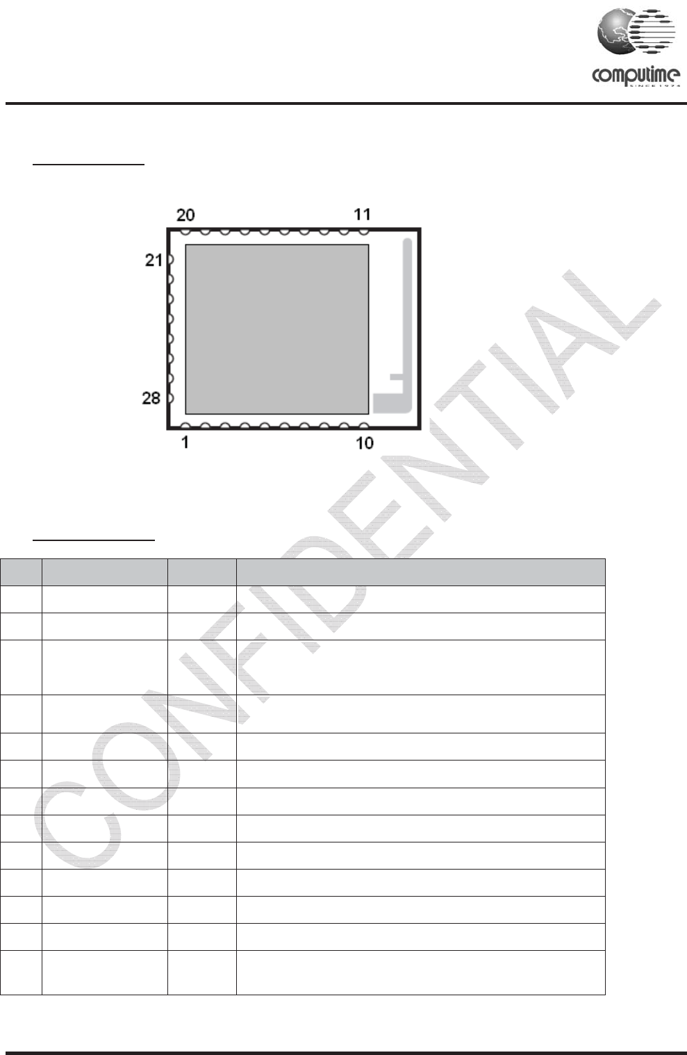
7. Pin Assignment
TOP VIEW
8. Pin Description
Pin# Signal Direction Description
1 SIF_CLK I Programming and debug interface, clock(internal pull down)
2 SIF_MISO O Programming and debug interface, master In/Slave Out
3 SIF_MOSI I
3URJUDPPLQJDQG'HEXJ,QWHUIDFH0DVWHU2XW6ODYH,Q
H[WHUQDOSXOOGRZQUHTXLUHGWRJXDUDQWHHVWDWHLQ'HHS
6OHHS0RGH
4 nSIF_LOAD I/O
3URJUDPPLQJDQG'HEXJ,QWHUIDFHORDGVWUREHRSHQFROOHFWRU
Z
SXOOXS
5 SDBG O Spare Debug Signal
6 LINK_ACTIVITY O Link and Activity signal
7 GROUND GND Ground
8 GROUND GND Ground
9 GROUND GND Ground
10 GROUND GND Ground
11 GROUND GND Ground
12 GROUND GND Ground
13 RX IDLE_EN I Enable the FEM in deep sleep mode , Active high. low level for RX
enable

ZigBee- Ready SoC RF Transceiver Modules CTL2607
Copyright © 2011 Computime Limited. All rights reserved. Rev. 2
Page 6
Pin# Signal Direction Description
14 GROUND GND Ground
15 V
BRD
Power Power Supply Input
16 nRESET I Active low chip reset(internal pull-up)
17 MOSI I
63,'DWD0DVWHU2XW6ODYH,QIURP+RVWWR
(0
N.C. I
When using the UART interface, this signal is left not connected.
18 MISO O SPI Data, Master In/Slave Out (from EM260 to host)
N.C. I When using the UART interface, this signal is left not connected.
19 SCLK I SPI Clock
N.C. I When using the UART interface, this signal is left not connected.
20 NC NC NC
21 nRTS O
UART Request To Send(enables host transmission) When using the
UART interface, this signal should be left unconnected if not used
N.C. I When using the SPI interface, this signal is left not connected.
22
nSSEL_INT I SPI Slave Select interrupt(from Host to EM260)
nCTS I
UART Clear To Send(enables EM260 transmission) When using the
UART interface, this signal should be left unconnected if not used.
nSSEL I SPI Slave Select (from Host to EM260)
N.C I When using the UART interface, this signal is left not connected .
23 PTI_EN O Frame signal of Packet Trace Interface(PTI)
24 PTI_DATA O Data signal of Packet Trace Interface(PTI)
25 TXD O UART Transmitted Date(from EM260 to Host)
N.C. I When using the SPI interface, this signal is left not connected.
26 nHOST_INT O SPI Host Interrupt Signal (from EM260 to Host)
RXD I UART Received Data(from Host to EM260)
27 nWAKE I SPI Wake Interrupt Signal (from Host to EM260)
N.C. I When using the UART interface, this signal is left not connected.
28 GROUND GND Ground
ZigBee- Ready SoC RF Transceiver Modules CTL2607
Copyright © 2011 Computime Limited. All rights reserved. Rev. 2
Page 7
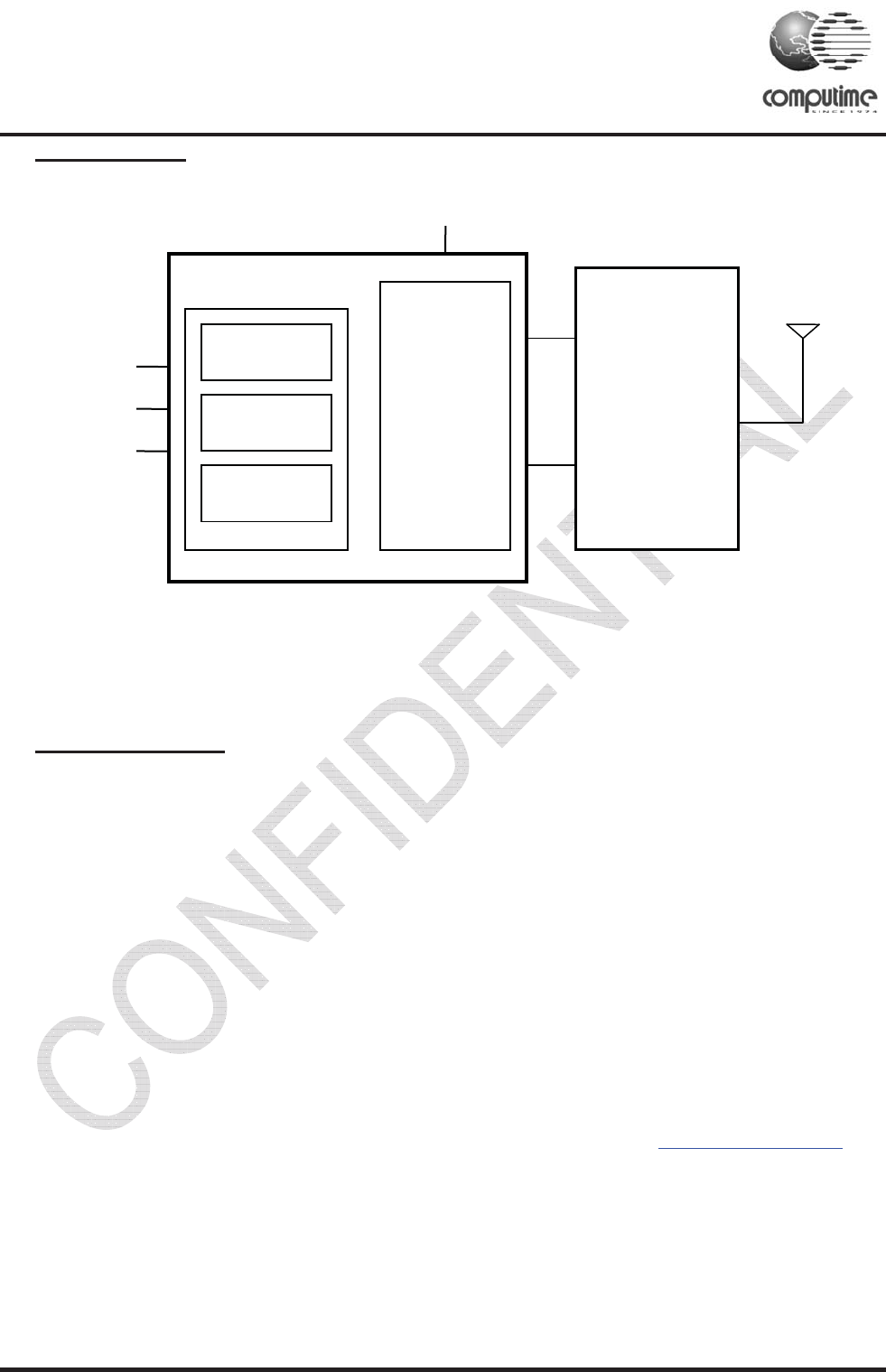
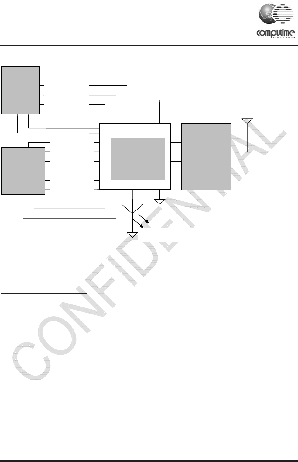
9. Block Diagram
Block Diagram
10. Circuit Description
The module contains an IEEE 802.15.4 compliant RF transceiver, high speed oscillator, RC oscillator and RF
FEM . The module is intended to running the Ember ZigBee software or other ZigBee network
implementation, depending on the specific version.
The application software together with the ZigBee protocol software stack can be programmed in Flash
memory through SIF module, using an evaluation board from Ember InSight Desktop.
To support user-defined applications, the module exposes the Ember Serial API over the SPI, which allows
application development to occur on a Host microcontroller of choice. In addition to the four SPI signals, two
additional signals, nHOST_INT and nWAKE, provide an easy-to-use handshake mechanism between the Host
and the module. Also, an integrated voltage regulator, power-on-reset circuitry, sleep timer, and low-power
sleep modes are available. The deep sleep mode draws less than 5ȝA allowing products to achieve long
battery life.
For further details on the transceiver (Ember EM260), please consult data sheet at http://www.ember.com
Rout
to
HOST
16 Bit Network Processo
r
User
Application
Zigbee
TM
Network
IEEE 802.15.4
MAC
IEEE
802.15.4 RF
Transceiver
2.7 – 3.6V
RF FEM

ZigBee- Ready SoC RF Transceiver Modules CTL2607
Copyright © 2011 Computime Limited. All rights reserved. Rev. 2
Page 8
11. SIF Module Programming and Debug Interface
SIF is a synchronous serial interface developed by Cambridge Consultants Ltd. It is the primary programming
and debug interface of the CTL2607. The SIF module allows external devices to read and write memory-
mapped registers in real-time without changing the functionality or timing of the XAP2b core.
The SIF interface provides the following:
IC production test (especially analog)
PCB production test
Firmware download
Product control and characterization
The pins are:
SIF_LOADB
SIF_CLK
SIF_MOSI
SIF_MISO
The maximum serial shift speed for the SIF interface is 48MHz. SIF interface accesses can be initiated even
when the chip is in idle, deep sleep or power down modes. An edge on nSIF_LOAD wakes the chip to allow
SIF cycles.
12. Power Management
The module supports four different power modes: active, idle, deep sleep, and power down.
Active mode is the normal, operating state of the module.
While in idle mode, code execution halts until any interrupt occurs. All modules including the radio continue
to operate normally. The EmberZNet stack automatically invokes idle as appropriate.
Deep sleep mode and power down mode both power off most of the functions, including the radio, and leave
only the critical chip functions powered. The internal regulator is disabled. All output signals are maintained
in a frozen state. Upon waking from deep sleep or power down mode, the internal regulator is re_enabled.
Deep sleep and power down result in the same sleep current consumption. The two sleep modes differ as
follows: the module can wake on both an internal timer and an external signal from deep sleep mode; power
down mode can only wake on an external signal.
ZigBee- Ready SoC RF Transceiver Modules CTL2607
Copyright © 2011 Computime Limited. All rights reserved. Rev. 2
Page 9
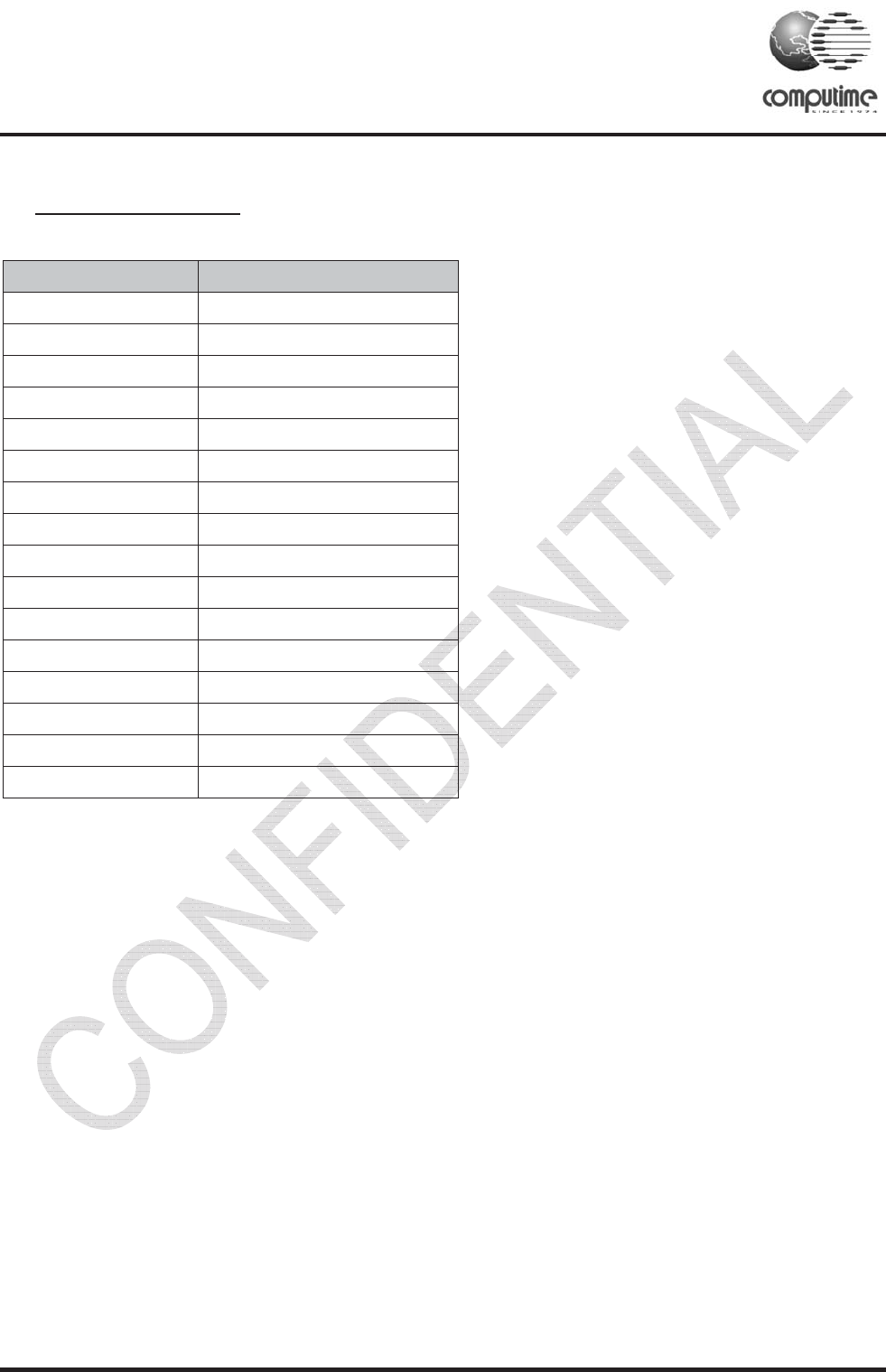
13. RF Frequency Detail
The following table shows the RF channels as defined by the IEEE 802.15.4 standard.
RF channel Frequency
11 2405MHz
12 2410MHz
13 2415MHz
14 2420MHz
15 2425MHz
16 2430MHz
17 2435MHz
18 2440MHz
19 2445MHz
20 2450MHz
21 2455MHz
22 2460MHz
23 2465MHz
24 2470MHz
25 2475MHz
26 2480MHz
The output power level of em250 can be configured in the range -32 to 4.5 dBm and the gain of FEM is 17dB,
So the module output can controlled in range -15 to 20dBm. The RF transceiver uses direct sequence spread
spectrum (DSSS) with 2 Mchip/s chip rate, giving a raw data rate of 250 kbit/s. The modulation format is
Offset – Quadrature Phase Shift Keying (O-QPSK). It is robust even under noisy environments when sharing
the same frequency band with other applications.
Note: the output power of em260 should be configured lower than -15dBm for 2480M channel to
Comply FCC
The use of RF frequencies and maximum allowed RF power should according to different national regulations.
The]CTL2607 is complying with the applicable regulations for the world wide 2.4GHz ISM band.
[Subject to final approval: Specifically it complies with the European Union R&TTE directive meeting EN 300 328 and
EN300 440 class 2. It also meets the FCC CFR47 Part15 regulations for use in the US and the ARIB T-66 for use in
Japan.]
-19dBm
-20 to 19dBm
ZigBee- Ready SoC RF Transceiver Modules CTL2607
Copyright © 2011 Computime Limited. All rights reserved. Rev. 2
Page 10
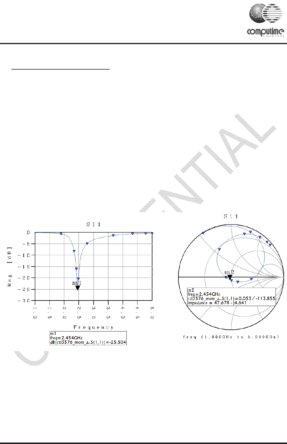
14. Antenna Design Considerations
The CTL2607 module includes an integrated PCB trace antenna. An optional MMCX connector can be
specified, enabling connection to a 50-ohm external antenna of the user’s choice..
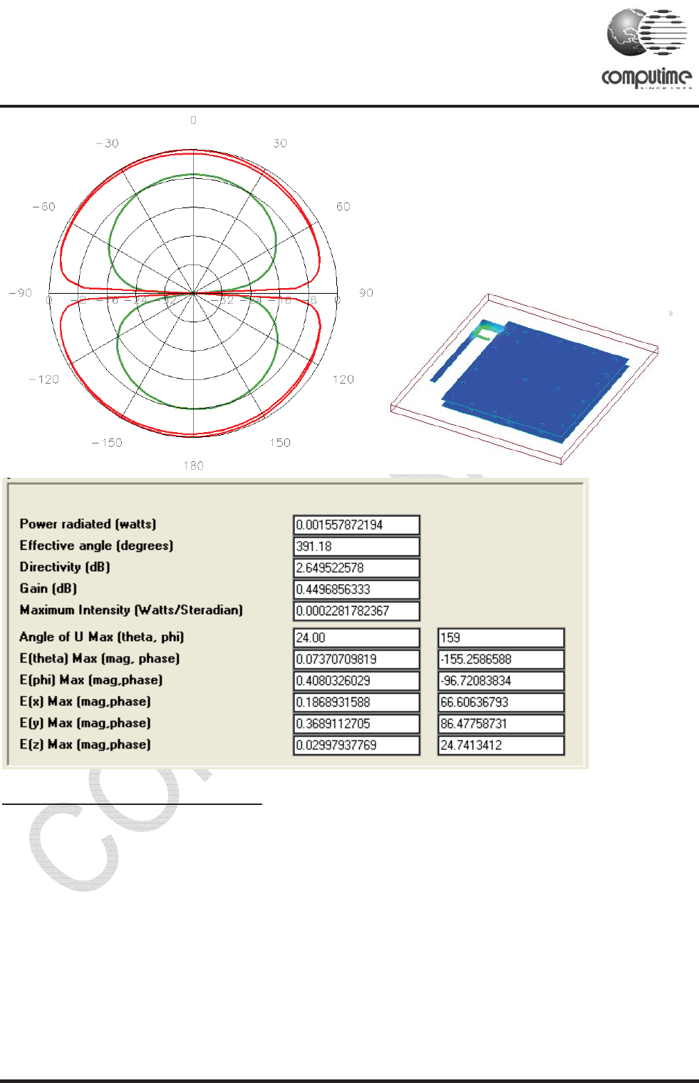
The PCB antenna employs an F-Antenna topology that is compact and supports an omni-directional radiation
pattern. To maximize antenna efficiency, an adequate ground plane must be provided on the host PCB. If
positioned correctly, the ground plane on the host board under the module can contribute significantly to
antenna performance.
The position of the module on the host board and overall design of the product enclosure contribute to antenna
performance. Poor design effects radiation patterns and can result in reflection, diffraction, and/or scattering
of the transmitted signal.
Here are some design guidelines to help ensure antenna performance:
• Never place the ground plane or route copper traces directly underneath the antenna portion of the
module.
• Never place the antenna close to metallic objects.
• In the overall design, ensure that wiring and other components are not placed near the antenna.
• Do not place the antenna in a metallic or metallized plastic enclosure.
• Keep plastic enclosures 1cm or more from the antenna in any direction
ZigBee- Ready SoC RF Transceiver Modules CTL2607
Copyright © 2011 Computime Limited. All rights reserved. Rev. 2
Page 11
15. PCB Layout Recommendations
For recommended layout pads for the module, please reference Mechanical Dimensions.
The area underneath the module should be covered with solder resist in order to prevent short circuiting the
test pads on the back side of the module. A solid ground plane is preferred. Unconnected pins should be
soldered to the pads, and the pads should be left floating. For the module version with integrated antenna, the
RF pad can be soldered, but the pad should not be connected further.
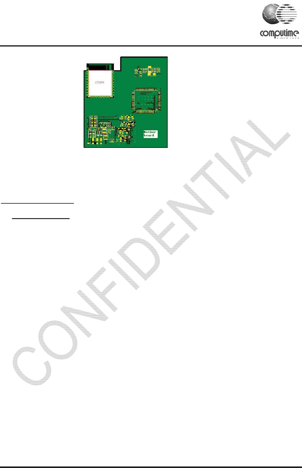
When using the onboard chip antenna, careful attention is required to the layout of the PCB where the module
is mounted. In the following picture a mother PCB is shown with a recommended placement of the module.
ZigBee- Ready SoC RF Transceiver Modules CTL2607
Copyright © 2011 Computime Limited. All rights reserved. Rev. 2
Page 12
A recommended placement of the module on a main PCB
16. Product Approvals
16.1FCC Approvals
The CTL2607 has been designed to meet all national regulations for World-wide use. Using the integrated
antenna it conforms to FCC CFR 47 Part 15 (USA).
This device complies with Part 15 of the FCC rules. Operation is subject to the following two conditions: (1)
this device may not cause harmful interference, and (2) this device must accept any interference received,
including interference that may cause undesired operation.
The device CTL2607 carries FCC authorization and is marked with the FCC ID Number. Whilst any device
into which this authorized module is installed will not normally be required to obtain FCC authorization, this
does not preclude the possibility that some other form of authorization or testing may be required for the
finished device.
When the CTL2607 module is integrated inside another device/product, then the outside surface of that
device/product must display a label referring to the enclosed module. This exterior label can use wording such
as “Contains Transmitter Module FCC ID:DICTCTL2607” or “Contains FCC ID: DICTL2607”
,
although any similar wording that expresses the same meaning may be used.
To meet the Section 15.209 emission requirements in the restricted frequency bands of Section 15.205,
the transceiver transmitter power for the CTL2607 module needs to be reduced from the typical
maximum setting on the upper channels ( 2480 MHz). Maximum values are 0dBm ( Configured the
output power of em260 lower than -15dBm).
FCC statement˖
If this equipment does cause harmful interference to radio or television reception, which can be determined by
turning the equipment off and on, the user is encouraged to try to correct the interference by one or more of
the following measures:
—Reorient or relocate the receiving antenna.
—Increase the separation between the equipment and receiver.
—Connect the equipment into an outlet on a circuit different from that to which the receiver is connected.
—Consult the dealer or an experienced radio/TV technician for help.

ZigBee- Ready SoC RF Transceiver Modules CTL2607
Copyright © 2011 Computime Limited. All rights reserved. Rev. 2
Page 13
Changes or modifications not expressly approved by the party responsible for compliance could void the user's authority
to operate the equipment.

ZigBee- Ready SoC RF Transceiver Modules CTL2607
Copyright © 2011 Computime Limited. All rights reserved. Rev. 2
Page 14
16.2CE Certificate
With the integrated antenna the CTL2607 has been tested and conforms to the following standards:
• Radio: ETSI EN300 328 V1.6.1
• EMC: ETSI EN301 489-17 V1.2.1
• EMC: ETSI EN301 489-1 V1.6.1
• Safety: IEC/EN60950-1
If the CTL2607 module is incorporated into an OEM product, the OEM product manufacturer must ensure
compliance of the final product to the European EMC, and low voltage/safety standards. A Declaration of
Conformity must be issued for each of these standards and kept on file as described in the R&TTE Directive.
The final product must not exceed the specified power ratings, as specified in this specification. If any of these
specifications are exceeded in the final product then a submission must be made to a notified body for
compliance testing to all of the required standards
ZigBee- Ready SoC RF Transceiver Modules CTL2607
Copyright © 2011 Computime Limited. All rights reserved. Rev. 2
Page 15
17. Typical application block
Example of application circuit
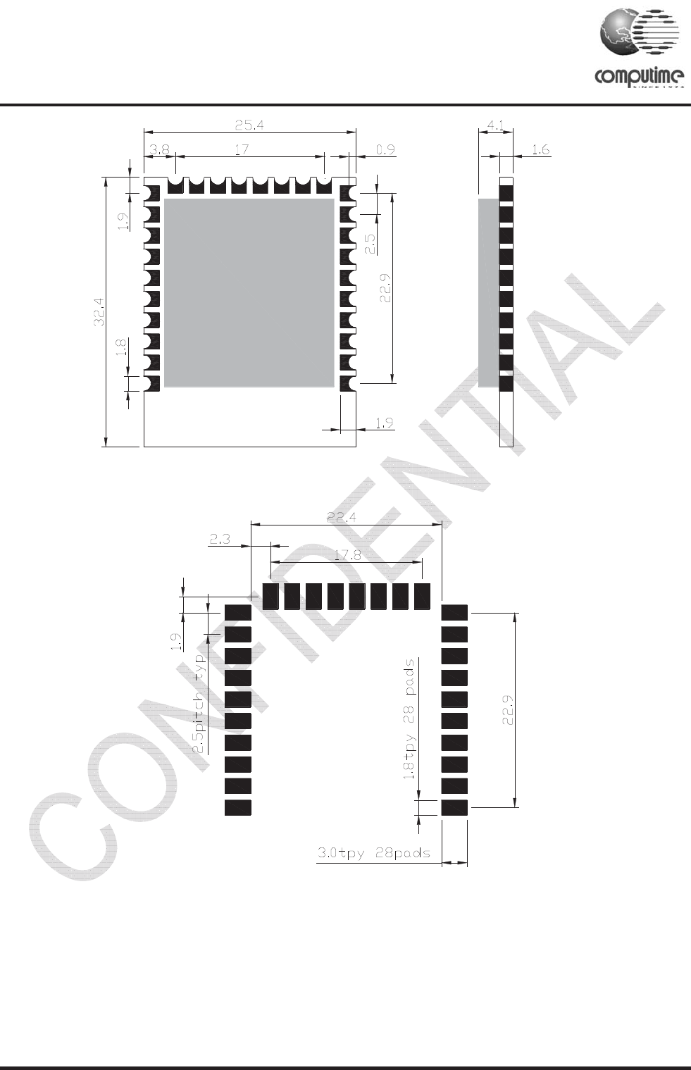
18. Mechanical Dimensions
Ember
EM260
2.7- 3.6V
Debug and
programming
interface
HOST
UP
NREST
PTI_EN
PTI-DATA
SIF_CLK
SIF_MISO
SIF_MOSI
LINK_ACTIVITY
FEM
NWAKE
NHOST_INT
NSSEL
SCLK
MISO
ZigBee- Ready SoC RF Transceiver Modules CTL2607
Copyright © 2011 Computime Limited. All rights reserved. Rev. 2
Page 16
Unit in mm˄
˄˄
˄Top View˅
˅˅
˅
Recommended PCB layout(unit in mm)
ZigBee- Ready SoC RF Transceiver Modules CTL2607
Copyright © 2011 Computime Limited. All rights reserved. Rev. 2
Page 17
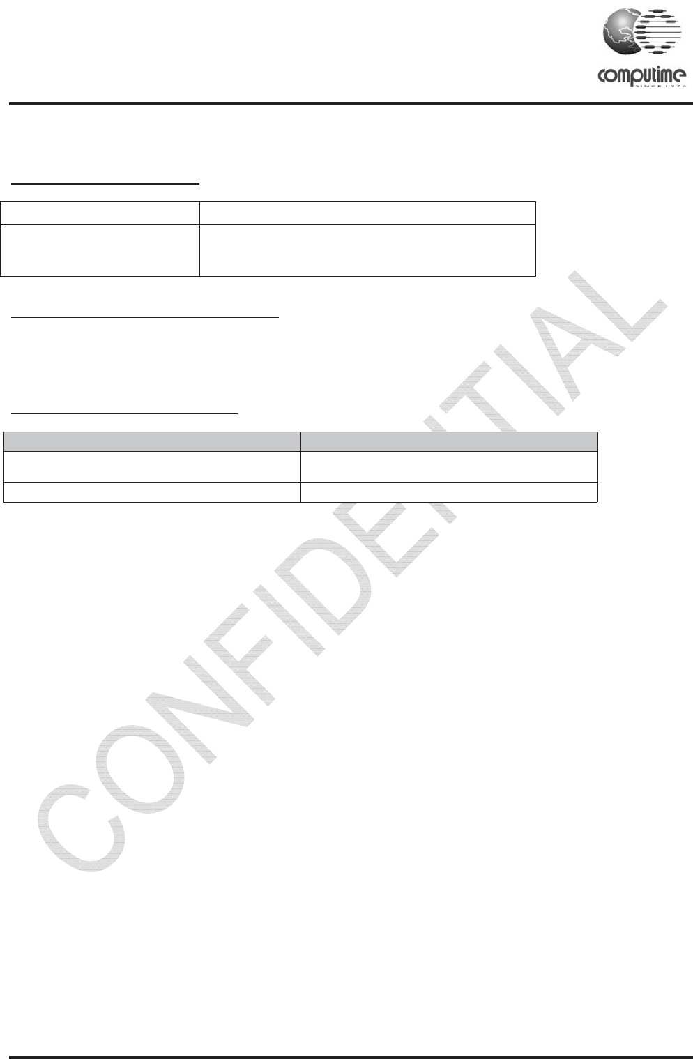
19. Ordering Information
Ordering Part Number Description
CTL2607 ZigBee-ready RF module, 1kB Flash, PCB trace
antenna, 20dBm Version FCC/CE certificate
20. Moisture Sensitivity Level (MSL)
MSL 3, per J-STD-033
21. Document Revision History
Document Revision change
1.0 Draft
1.1 Add MSL

ZigBee- Ready SoC RF Transceiver Modules CTL2506
Copyright © 2011 Computime Limited. All rights reserved. Rev. 2
Contact information
COMPUTIME CORPORATE HQ
17/F, Great Eagle Centre,
23 Harbour Road, Wanchai,
Tel: +852.2260.0300
Fax: +852.2790.3996
e-mail: hq@computime.com
COMPUTIME NORTH AMERICA HQ,
4700 Duke Dr.
Suite 200
Mason OH 45040
USA
Tel: +1(513).398.2579
Fax: +1(513).754.8955
e-mail: na@computime.com
CINCINNATI WIRELESS SOLUTIONS LTD
4700 Duke Dr.
Suite 200
Mason OH 45040
USA
Tel: +1(513).754.8935
Fax: +1(513).754.8955
e-mail: ctws@computime.com
COMPUTIME JAPAN
3-18-9 Roppongi Minatoku,
Tokyo 106-0032,
Japan
Tel: (03).3583.8411
Fax: (03).3583.3799
e-mail: cj@computime.com
About Computime
Founded in 1974, Computime is a global technology, brand and manufacturing company providing
innovative automation and control solutions to customers in commercial, industrial and consumer
markets.
The Company provides technologies and products that save energy and make people's lives more
productive and comfortable.

FCC Statement
Thisdevicecomplieswithpart15oftheFCCRules.Operationissubjecttothefollowingtwoconditions:(1)Thisdevicemaynotcauseharmful
interference,and(2)thisdevicemustacceptanyinterferencereceived,includinginterferencethatmaycauseundesiredoperation.
Changes or modifications not expressly approved by the party responsible for compliance could void the user's authority to operate the
equipment.
NOTE:ThisequipmenthasbeentestedandfoundtocomplywiththelimitsforaClassBdigitaldevice,pursuanttoPart15oftheFCCRules.
Theselimitsaredesignedtoprovidereasonableprotectionagainstharmfulinterferenceinaresidentialinstallation.Thisequipmentgenerates,
usesandcanradiateradiofrequencyenergyand,ifnotinstalledandusedinaccordancewiththeinstructions,maycauseharmfulinterference
toradiocommunications. However,there isno guaranteethatinterferencewill not occurin a particular installation.If this equipment does
cause harmful interference to radio or television reception, which can be determined by turning the equipment off and on, the user is
encouragedtotrytocorrecttheinterferencebyoneormoreofthefollowing
measures:
ͲͲReorientorrelocatethereceivingantenna.
ͲͲIncreasetheseparationbetweentheequipmentandreceiver.
ͲͲConnecttheequipmentintoanoutletonacircuitdifferentfromthattowhichthereceiverisconnected.
ͲͲConsultthedealeroranexperiencedradio/TVtechnicianforhelp.
FCCRadiationExposureStatement
Themodularcanbeinstalledorintegratedinmobileorfixdevicesonly.Thismodularcannotbeinstalledinanyportabledevice,forexample,
USBdongleliketransmittersisforbidden.
ThismodularcomplieswithFCCRFradiationexposurelimitssetforthforanuncontrolledenvironment.ThistransmittermustnotbecoͲlocated
oroperatinginconjunctionwithanyotherantennaortransmitter.Thismodularmustbeinstalledandoperatedwithaminimumdistanceof20
cmbetweentheradiatoranduserbody.
IftheFCCidentificationnumberisnotvisiblewhenthemoduleisinstalledinsideanotherdevice,thentheoutsideofthedeviceintowhichthe
module is installed must also display a label referring to the enclosed module. This exterior label can use wording such as the following:
“ContainsTransmitterModuleFCCID:2AAUQͲCTLB357OrContainsFCCID:2AAUQͲCTLB357 ā
whenthemoduleisinstalledinsideanotherdevice,theusermanualofthisdevicemustcontainbelowwarningstatements;
1.ThisdevicecomplieswithPart15oftheFCCRules.Operationissubjecttothefollowingtwoconditions:
(1)Thisdevicemaynotcauseharmfulinterference.
(2)Thisdevicemustacceptanyinterferencereceived,includinginterferencethatmaycauseundesiredoperation.
2. Changes or modifications not expressly approved by the party responsible for compliance could void the user's authority to operate the
equipment.
Thedevicesmustbeinstalledandusedinstrictaccordancewiththemanufacturer'sinstructionsasdescribedintheuserdocumentationthat
comeswiththeproduct
“Contains Transmitter Module FCC ID: 2AAUQ-CTL2607 Or Contains FCC ID: 2AAUQ-CTL2607 ā

IC STATEMENT
ThisdevicecomplieswithIndustryCanada’slicenceͲexemptRSSs.Operationissubjecttothefollowingtwoconditions:
(1)Thisdevicemaynotcauseinterference;and
(2)Thisdevicemustacceptanyinterference,includinginterferencethatmaycauseundesiredoperationofthedevice.
CetappareilestconformeauxCNRexemptesdelicenced'IndustrieCanada.Sonfonctionnementestsoumisauxdeuxconditionssuivantes:
(1)Cedispositifnepeutcauserd'interférences;et
(2)Cedispositifdoitacceptertouteinterférence,ycomprislesinterférencesquipeuventcauserunmauvaisfonctionnementdel'appareil.
ICRadiationExposureStatement
Themodularcanbeinstalledorintegratedinmobileorfixdevicesonly.Thismodularcannotbeinstalledinanyportabledevice,forexample,
USBdongleliketransmittersisforbidden.
ThismodularcomplieswithICRFradiationexposurelimitssetforthforanuncontrolledenvironment.ThistransmittermustnotbecoͲlocated
oroperatinginconjunctionwithanyotherantennaortransmitter.Thismodularmustbeinstalledandoperatedwithaminimumdistanceof20
cmbetweentheradiatoranduserbody.Cettemodulairedoitêtreinstalléetutiliséàunedistanceminimumde20cmentreleradiateuretle
corpsdel'utilisateur.
If the IC number is not visiblewhen the module is installed inside another device,then the outside of the device into which themodule is
installedmustalsodisplayalabelreferringtotheenclosedmodule.Thisexteriorlabelcanusewordingsuchasthefollowing:
“ContainsIC:1700DͲCTLB357ā
whenthemoduleisinstalledinsideanotherdevice,theusermanualofthisdevicemustcontainbelowwarningstatements;
1.ThisdevicecomplieswithIndustryCanada’slicenceͲexemptRSSs.Operationissubjecttothefollowingtwoconditions:
(1)Thisdevicemaynotcauseinterference;and
(2)Thisdevicemustacceptanyinterference,includinginterferencethatmaycauseundesiredoperationofthedevice.
2.CetappareilestconformeauxCNRexemptesdelicenced'IndustrieCanada.Sonfonctionnementestsoumisauxdeuxconditionssuivantes:
(1)Cedispositifnepeutcauserd'interférences;et
(2)Cedispositifdoitacceptertouteinterférence,ycomprislesinterférencesquipeuventcauserunmauvaisfonctionnementdel'appareil.
Thedevicesmustbeinstalledandusedinstrictaccordancewiththemanufacturer'sinstructionsasdescribedintheuserdocumentationthat
comeswiththeproduct
“Contains IC:1700D-CTL2607ā