Comtech EF Data MTSMUV2MT2011 Satellite Modem User Manual MTS User s Manual
Comtech EF Data Satellite Modem MTS User s Manual
Contents
- 1. manual1 1half
- 2. manual2 2nd half
- 3. manual3 3rd half
- 4. manual4 4th half
- 5. manual5 5th half
manual2 2nd half
Contract No. DAAB15-99-D-0014 MTS Users Manual Revision: 1.9.1a
Page 9-1
9. System Administrator Tasks
9.1 Using MTS Messenger Help
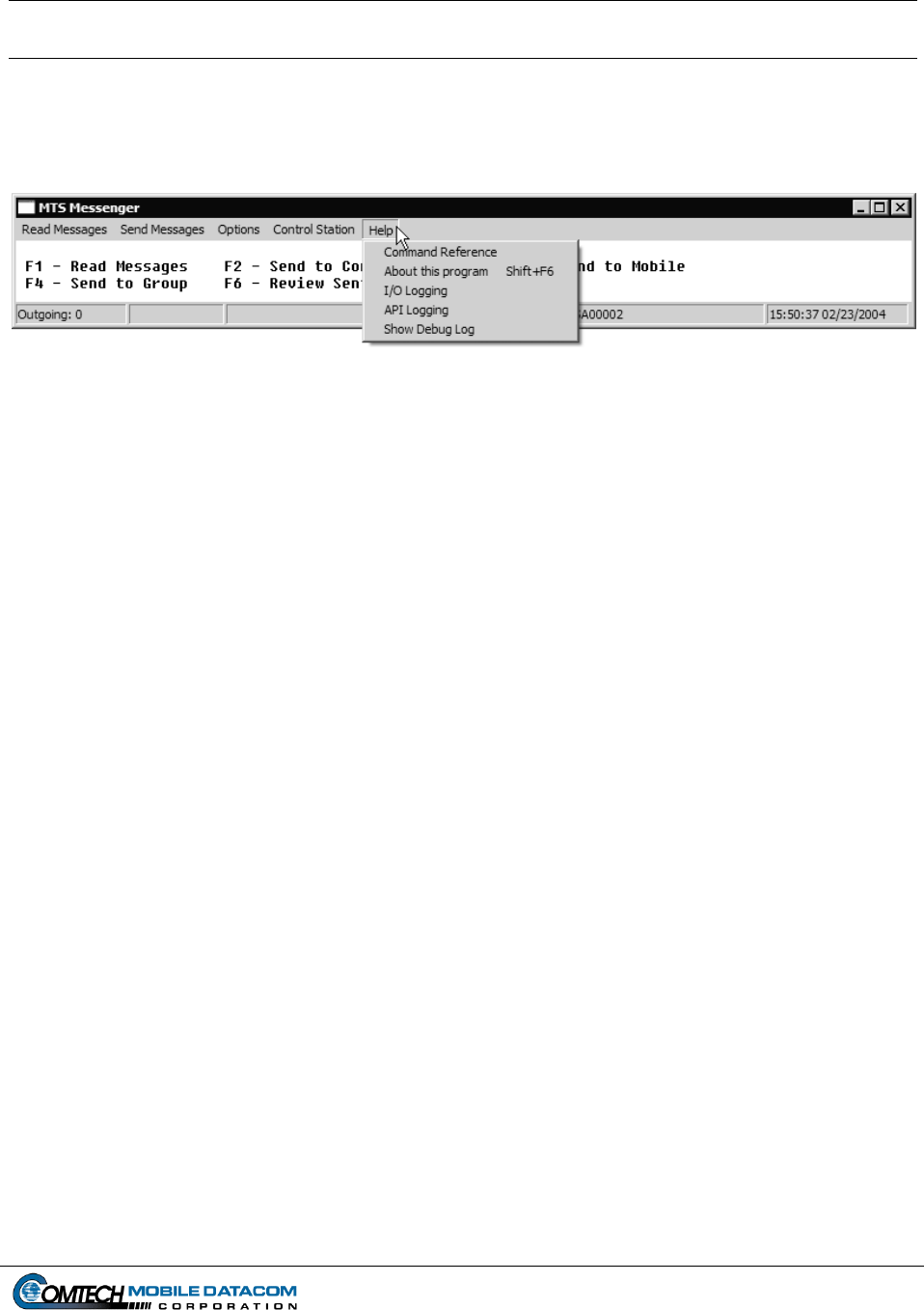
Select the Help menu from the menu bar. Figure 9-1 shows the menu that will appear.
Figure 9-1 Help Menu
Command Reference will display the function key command reference in the display
screen (see Section 5.1.1).
About this Program will display the version number of the MTS Messenger program
(see Section 7.2.1).
I/O Logging, API Logging, and Show Debug Log all show protocol traffic to and from
the satellite transceiver. The Debug Log is the only log that will be used by the System
Administrator.
9.1.1 Debug Log
MTS Messenger has a built-in diagnostic function, the Debug Log that may help in
the event of trouble. Although this function was created for Comtech Mobile
Datacom’s development engineers, a trained Army System Administrator working in
conjunction with Comtech Mobile Datacom’s Support Personnel can determine some
basic status information from the Debug Log.
The diagnostic function displays data between the terminal and MTS Messenger and
between MTS Messenger and Tracerlink. The steps below outline how to activate the
Debug Log and how to interpret some of the data in the log. Again however, it is
recommended that the system administrator not try to interpret this log without
support from Comtech Mobile Datacom.
Steps for Opening and Low-Level Interpretation of the Debug Log:
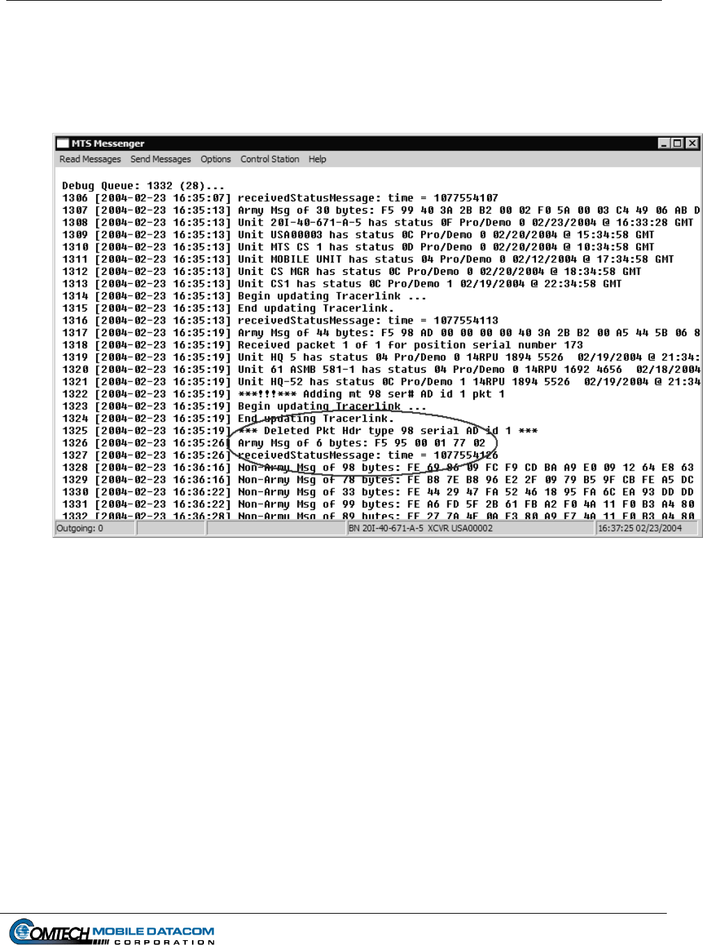
(1) Select Help Show Debug Log from the Help menu. When this is done, the
Command displayed in the main panel will change to display diagnostic
information. The diagnostic information includes all data received from and sent
to the terminal, and all data sent to the Tracerlink map. Lines of the form "Army
Contract No. DAAB15-99-D-0014 MTS Users Manual Revision: 1.9.1a
Page 9-2
Msg of X bytes" indicate a message was received from the satellite terminal (see
the red circled message in Figure 9-2). To verify the terminal is receiving
messages from the satellite, view this screen for several minutes to see that
messages are periodically arriving. If you receive a message, go to step 2. If you
do not receive a message after 10 minutes, go to step 3.
Figure 9-2 Sample Debug Log
(2) To revert back to the Command Reference select Help Command Reference.
The Command Reference screen (also referred to as the standard MTS Messenger
window) should appear as in Figure 5-5.
(3) If no messages containing the string "Army Msg of X bytes:" arrive for a 10-
minute period, the terminal is not receiving messages from the satellite. Check
that the LED lights are illuminated (see Section 9.2). If the LED's are lit, the
terminal may be blocked from satellite view by trees or buildings. Proceed to step
4. If the LED lights are not illuminated follow the procedures outlined in section
9.2.
(4) Move the terminal into a clear area without any obstructions in the direction of the
satellite. If the terminal has power and a view of the satellite, but is still not
communicating, the terminal may be the problem, proceed to step 5.
Contract No. DAAB15-99-D-0014 MTS Users Manual Revision: 1.9.1a
Page 9-3
(5) At this point it will be necessary to look at the terminal directly without MTS
Messenger. You will need assistance from a Comtech Mobile Datacom engineer.
Please call the Comtech Mobile Datacom Support Center at 1-888-428-2101.
(6) To remove the debug messages, select Help Show Debug Log again.
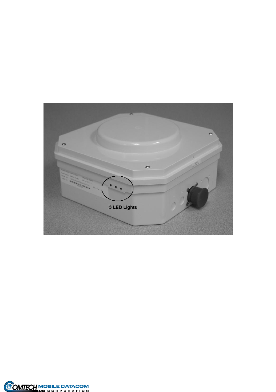
9.2 LEDs (Light Emitting Diodes)
The transceiver is equipped with three colored LEDs (light emitting diodes). The LEDs
are colored Red, Yellow and Green. The LEDs are located on the side of the MT-2011
(shown in Figure 9-3) and MT-2010 terminals.
Figure 9-3 LEDs on Transceiver
The LEDs provide information on:
Whether the terminal is receiving power. If there are no lights, the terminal is
not receiving power.
The transceiver startup process. The LED lights will cycle a number of times
(go from Red to Yellow to Green in what appears to be a random order)
during the initial startup process. Although the lighting process appears
random, it actually shows the boot-up process of the firmware in the
transceiver.
If the terminal is functioning in standard operating mode. After the startup
process, the terminal will go into its standard operating mode. During this
mode the green and yellow lights will illuminate in a semi-constant fashion.

Contract No. DAAB15-99-D-0014 MTS Users Manual Revision: 1.9.1a
Page 9-4
If the terminal is sending a message. The Red LED will flicker for a few
milliseconds when transmitting a message.
9.2.1 No LED Lights on the Transceiver (MT-2010 and MT-2011) & Check Cables
The most important indicator that the LEDs provide is whether the terminal is
receiving power. If the LEDs do not turn on when a user turns on the control box,
there could be one of three problems.
(1) The most obvious problem would that the control box isn’t actually turned on.
Turn on the control box. If this solves the problem skip all the subsequent steps.
If the problem persists proceed to step 2.
(2) Check to see if there are loose cables. Check that the cable to the transceiver is
appropriately fastened. Ensure that the transceiver cable is not damaged at the
control box. If you suspect that a cable from the control box to the transceiver has
been damaged, mount the transceiver on another vehicle. Do not touch the cable
if you see exposed wire. Plug in the transceiver to the other vehicle’s control box,
turn on the control box and see if the transceiver’s LEDs illuminate. If the
transceiver’s LEDs do not illuminate go to step 3.
(3) Check the pins on connector of the transceiver. Are the pins bent or broken? Do
the pins show signs of any other damage? If the answer to either of these
questions is yes, contact your System Administrator, or the unit CSSAMO. If the
pins appear OK, go to step 4.
(4) Check to see that the control boxes you have used in steps 1-3 are functioning
correctly. Try powering up another transceiver on the control boxes you have
been using. If you have checked the control boxes and you think that the control
boxes are working correctly, contact your Control Station operator or the unit
CSSAMO.
9.3 Checking and Troubleshooting TracerLink
If TracerLink Map Viewer is not showing vehicles that you believe it should be
showing follow the steps outlined below. This section assumes that the user
understands how to display and hide vehicles and groups. It assumes that all Control
Groups have been set to show, but the user is still not seeing a known unit (vehicle).
9.3.1 Checking that Vehicle Server COMM is Active
The Vehicle Server window communicates with MTS Messenger. MTS Messenger
passes position data to TracerLink Vehicle Server, so that the Map Viewer can
Contract No. DAAB15-99-D-0014 MTS Users Manual Revision: 1.9.1a
Page 9-5
display the appropriate vehicle icons. To verify that the Vehicle Server is actively
communicating with MTS Messenger, perform the following steps:
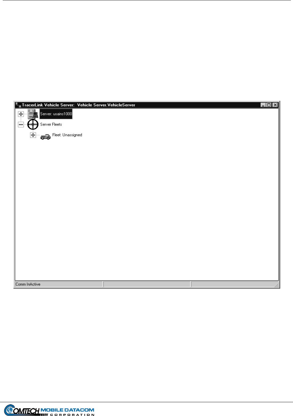
(1) Maximize the Vehicle Server window. Usually this window will be minimized,
however to verify connectivity between MTS Messenger and TracerLink you will
need to maximize the window.
(2) Check that the lower left status bar says COMM Active. This means the
Tracerlink Vehicle Server is connected to MTS Messenger. In Figure 9-4, the
lower left status bar shows COMM InActive.
Figure 9-4 Vehicle Server Window – COMM InActive
(3) Close the Vehicle Server and the Map Viewer. Shut down (close) MTS
Messenger.
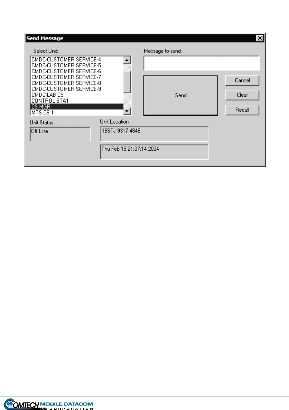
(4) Restart MTS Messenger. Make sure MTS Messenger is functioning
appropriately. Using the send function in MTS Messenger, check that the vehicle
is on-line in MTS Messenger and showing its position, or that it is off-line but that
its last report is available. Figure 9-5 illustrates a unit, CS MGR, that is off-line,
but that its last position report was at MILGRID 18TJ 9317 4846. If position
Contract No. DAAB15-99-D-0014 MTS Users Manual Revision: 1.9.1a
Page 9-6
information is available in MTS Messenger, it should be available in TracerLink,
proceed to Step 5.
Figure 9-5 Check Status of Vehicle via MTS Messenger
(5) Restart Vehicle Server, and then restart the Map Viewer. The map viewer is
different -- it can be shut down and restarted without restarting the vehicle server
or MTS Messenger. If the vehicles that previously were not seen are now in-
view, you can stop troubleshooting. If the vehicles are still not in-view in the
TracerLink Map Viewer you will need to check if the vehicle is Connected in the
Vehicle Server Kit Control window.
9.3.2 Deleting and Connecting Server
There are occasions when you may suspect a problem between the TracerLink Map
Viewer and the vehicle server. In that case, you want to delete and reconnect the
server.
NOTE: Deleting the server will shut down Tracerlink Pro. Tracerlink Pro must
be re-started after deletion.
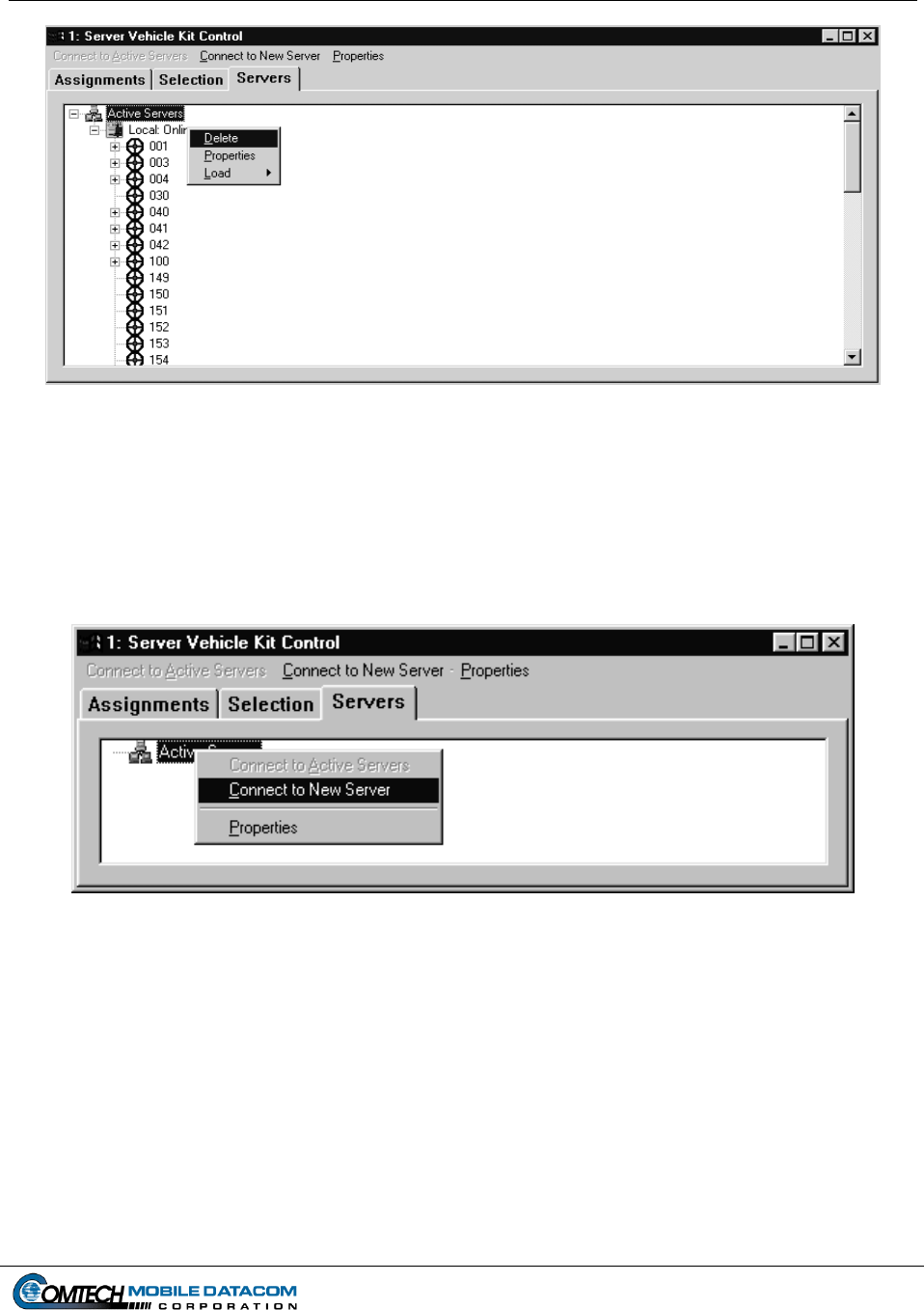
(1) Select vehicle. The Server Vehicle Control window is displayed (see Figure 9-6).
Contract No. DAAB15-99-D-0014 MTS Users Manual Revision: 1.9.1a
Page 9-7
Figure 9-6 Server Vehicle Kit Control – Delete a Server
(2) Right click on local server. Click on delete. The user will be asked to confirm
whether or not the user really wants to delete the server. Click on yes.
(3) To connect a new server, right click on the Active Server icon (see Figure 9-7).
Figure 9-7 Server Vehicle Kit Control – Connect to Server
(4) Select the Connect to Server option (see Figure 9-7)
Contract No. DAAB15-99-D-0014 MTS Users Manual Revision: 1.9.1a
Page 9-8
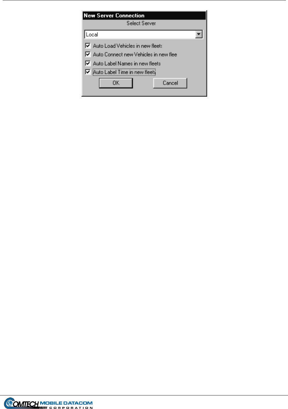
Figure 9-8 Server Vehicle Kit Control –New Server Connection – Local
(5) The New Server Connection window will appear. In this window are a number
of check boxes. If you want the Map Viewer to see vehicles automatically as well
as the vehicle’s corresponding name and time of last position report, click on all
of the appropriate boxes and then click OK.
9.3.3 Connecting & Disconnecting Vehicles / Groups in the Vehicle Server Kit
Control Window
Groups and vehicles can be disconnected (Not Connected) in TracerLink so that a
user can no longer display (show) or hide the group and units. The system
administrator may want to disconnect an entire group for a user or a group of users so
that the user or group does not see the position (icons) of another group, (this assumes
the user is a Control Station and that has been assigned to several groups). For
example, Group 001 users may not want to see Group 002 positions. Group 001’s
TracerLink configurations could be set with Group 002 as Not Connected.
Conversely, if Group 001 wanted to see Group 002 (in other words Connect Group
002), after it was Not Connected, the configuration would need to be changed again.
A potential problem may occur when a user has inadvertently disconnected a vehicle
or a group of vehicles. The System Administrator will need to re-connect the vehicle
or group. The steps needed to re-connect a disconnected group are as follows:
(1) Check to see if the vehicle you want to see has been truly been Not Connected
using the Server Vehicle Kit Control Window.
(2) Once the Server Vehicle Kit Control Window is open, select the Servers tab
(see Figure 9-9).
Contract No. DAAB15-99-D-0014 MTS Users Manual Revision: 1.9.1a
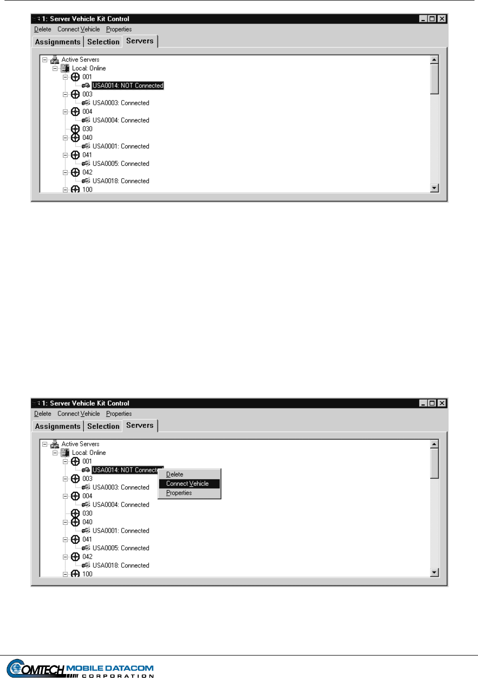
Figure 9-10 Connecting A Vehicle or Group
Page 9-9
Figure 9-9 Server Vehicle Kit Control Window Server Tab
(3) To change a unit which is Not Connected simply select the Not Connected
vehicle, then right click, and finally choose Connect Vehicle as in Figure 9-10.
Once you choose Connect the vehicle will appear as Connected. You can follow
the same procedure to Connect the entire group (fleet). Select the group, then
right click, and finally choose Connect. To disconnect a vehicle or group follows
the same procedures, except instead of choosing a Not Connected vehicle or
group, you choose one that is Connected.

Contract No. DAAB15-99-D-0014 MTS Users Manual Revision: 1.9.1a
Page 9-10
(4) Now you will need to ensure that the connection changes are saved for the next
time the user launches TracerLink Vehicle Server and TracerLink Map Viewer.
Therefore, close the Server Vehicle Kit Control window. Right click on the Map
Viewer and select Save TracerLink. If the user doesn’t want to overwrite the
previous configuration, select Save Tracerlink As. This will allow the user to
save the configuration as a different filename.

Contract No. DAAB15-99-D-0014 MTS Users Manual Revision: 1.9.1a
Page 10-1
10. Warranty
Comtech Mobile Datacom Corporation is obligated, under the provisions of the Warranty
for items delivered pursuant to this contract, to repair or replace or otherwise provide a
remedy for warranted items only if damage or loss results from or is caused by the
warranted item. Comtech is not obligated to provide repair, replacement or other
remedies in the event that damage or loss is the result of or is caused by actions or events
other than the warranted item, to include such causes as (1) misuse or abuse of the item
beyond the use contemplated in the Specification; (2) accidental damage. To include
aircraft crashes; (3) combat damage; (4) natural disasters, to include flood, earthquake,
hurricane, tornado; and (5) fires or explosions not originating on or within the warranted
item.
Comtech will provide a thirty-nine month warranty including parts and labor for all
equipment delivered under the MTS contract. The warranty may include on-site
procedures or mail-in or a combination of both. Comtech will provide no-cost repair for
MTS equipment delivered to Comtech by mail or commercial carrier. Comtech will bear
all shipping and packaging costs both from and to Government sites, and will be
responsible for equipment from time of shipment to safe return to the Government site.
Equipment located in CONUS, Alaska, Hawaii, Germany, Korea and Southwest Asia
(including but not limited to Kuwait, Saudi Arabia, Bahrain, and Qatar), will be returned
to a fully operational status or replaced with a fully operational unit within seventy-two
(72) hours of a bona fide attempt to report the problem to Comtech using the customer
assistance services provided under this contract. Equipment located in all other locations
will be returned to a fully operational status or replaced with a fully operational unit
within two hundred forty (240) hours of a bona fide attempt to report the problem to
Comtech using the customer assistance services provided under this contract. A bona fide
attempt is established once the user has established contact with the staffed telephone
support service or after a user leaves an answering service machine message or receives a
delivery receipt notice to an e-mail, World-Wide Web or satellite message request for
service.
The Precision Lightweight GPS Receiver, PLGR, is not covered under Comtech Mobile
Datacom Corporations warranty for MTS.

Contract No. DAAB15-99-D-0014 MTS Users Manual Revision: 1.9.1a
Page 10-2
PLGR’s requiring warranty replacement will be returned to Rockwell Collins INC.
To return a PLGR to the manufacturer:
1. Remove the main power battery (if installed).
2. Do not remove the 3.6 volt memory battery
3. Package the PLGR to protect from in-transit damage.
4. Use DD Form 1149, include the fault code or written explanation of the fault.
5. Ship to Rockwell Collins INC
ATTN: Service Center MS 134-141
855 35th Street NE
Cedar Rapids, IA 52402-3613
Mark for: AN/PSN-V1 Warranty

Contract No. DAAB15-99-D-0014 MTS Users Manual Revision: 1.9.1a
Page 11-1
11. Spare parts
When Comtech replaces a defective part during the warranty period, the newly installed
part will become Government property. The defective part will become Comtech
property. The effective warranty for all replacement parts installed during the initial
warranty period will be equal to the remaining warranty period on the original item or 90
calendar days, whichever is greater.
The Precision Lightweight GPS Receiver, PLGR, is provided with the MTS. If
replacements parts are required for a defective PLGR, alert your unit supply.
Replacement accessory parts will be ordered IAW your unit supply SOP. The PLGR is
not covered under the Comtech warranty clause.

Contract No. DAAB15-99-D-0014 MTS Users Manual Revision: 1.9.1a
Page 12-1
12. Required Tools
There are no tools necessary to attach the CS or V2 MTS configurations to their pre-
installed mounting brackets.
Contract No. DAAB15-99-D-0014 MTS Users Manual Revision: 1.9.1a
Page 13-1
13. Frequently Asked Questions
13.1 What group am I in?
Mobile (V2) users can only be in one group. Control Station (CS) users can be in one or
many groups. To check which group you are a member of, open the group message
window (F4 of Send Message To Group) in MTS Messenger.
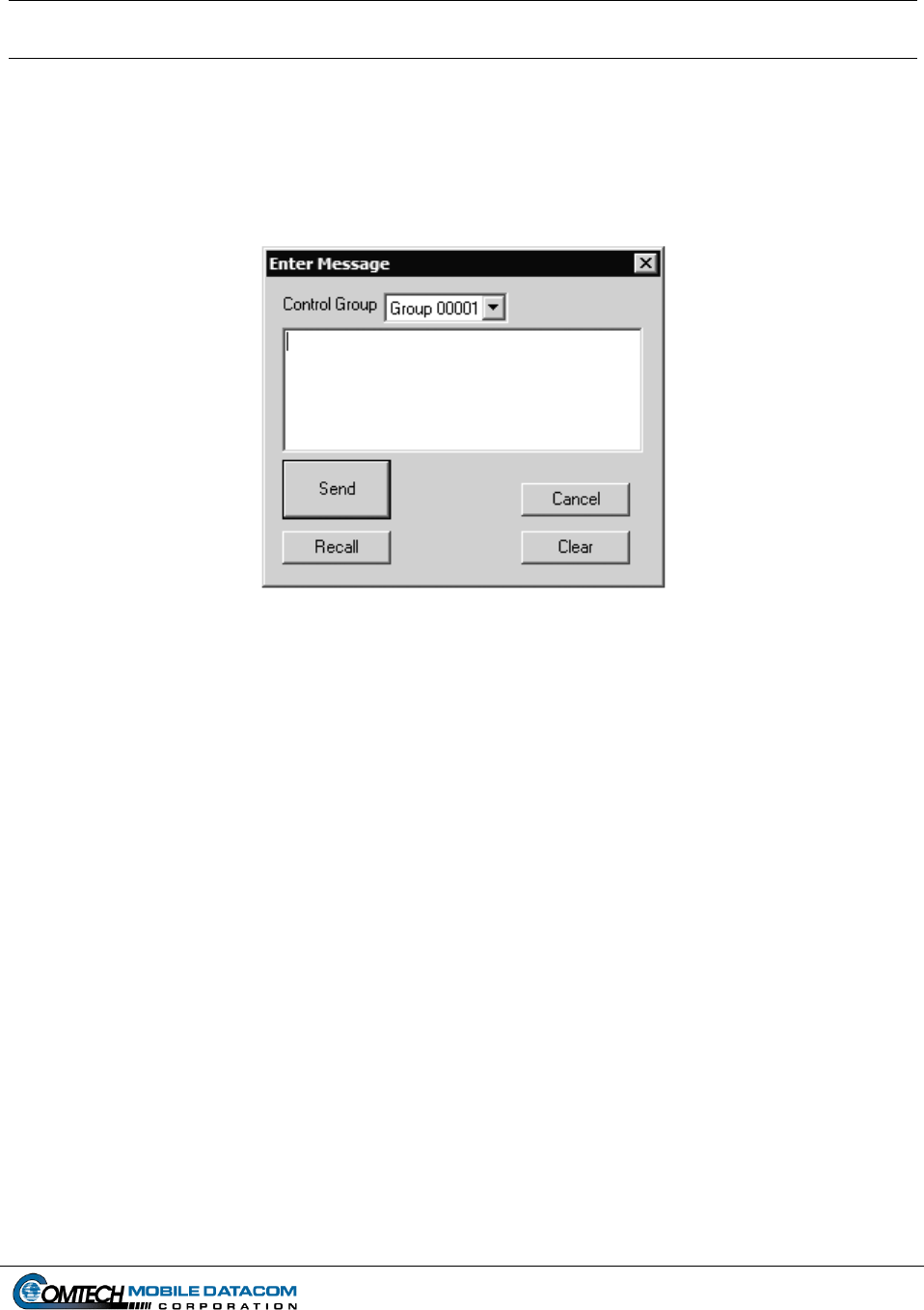
Figure 13-1 Enter Group Message Dialog Box
Notice that in this window, the user is a member of Group 00001. If the user was a
Control Station, the user could use the pull down window to see what other groups the
user was currently a member of.
Note: Groups are assigned numbers in MTS Messenger and letters in TracerLink. See
FAQ 2 for an explanation.
13.2 Why can't I see myself on the map?
If your unit is not appearing on the map, first check to see if you are looking in the right
area of the map. If you still do not see yourself check the following:
(1) Is your transceiver assigned to a group? If you are not assigned to any group, you
will not be able send, receive to any other transceiver. You will also not be able
to see your unit on the map, (see Section 5.4.3).
(2) Is the Vehicle Server window open, and does it show COMM ACTIVE?
(3) If the TracerLink map viewer has been disconnected from the Vehicle Server.

Contract No. DAAB15-99-D-0014 MTS Users Manual Revision: 1.9.1a
Page 13-2
13.3 Why can’t I see other members of my group?
There are three reasons why you might not see any other units in your group.
(1) If you are not assigned to any group, you will not be able send messages to or
receive messages from any other transceiver. You will also not be able to see
your unit on the map.
(2) It can take several minutes to see your group members appear after starting MTS
Messenger.
(3) The other units in your group may be hidden. Follow the steps outlined in
sections 6.6.4 and 6.6.5 to reveal hidden vehicles.
13.4 Can I print my maps in TracerLink?
There is no direct printing function in TracerLink. However, a user may perform a
screen capture, then paste the screen capture in WordPad, or MS Paint. A screen capture,
literally takes a picture of what is on your screen.
(1) To perform a screen capture press the PrtSc button. This button can be found on
the top row of the Control Station laptop keyboard.
(2) Open Word Pad. To open word go to the Start button, select Program Files, then
select Accessories, and finally select WordPad. (StartProgram Files
Accessories WordPad).
(3) Paste the screen capture. To paste the screen capture, choose the Edit menu
option, the select Paste. (Edit Paste). A quicker way to do this would be to
press the Ctrl key and the “V” key simultaneously.
Note: Only Control Station users have printers, mobile (V2) users have no printing
capability.
13.5 Can I send messages via TracerLink?
No.
13.6 I cannot open my MTS transit case, what am I doing wrong?
If the case does not open easily, verify that the four butterfly clips are unfastened. If the
butterfly clips are all unfastened and the case still does not open, depress the pressure
release valve on the side of the transit case.

Contract No. DAAB15-99-D-0014 MTS Users Manual Revision: 1.9.1a
Page 13-3
13.7 I can’t see messages I sent yesterday. Can I save my messages in MTS
Messenger?
No. For security reasons the Army has required that messages never be saved on any of
the MTS computers. Once you log out of MTS Messenger all of your messages will be
erased. Control Stations may print a message log, but that log will not be saved on the
Control Station computer.
13.8 Why can’t I see my vehicle/control station icons?
The unit must be able to see both GPS and Communication Satellites. It must receive
good PLGR information to work properly. First, ensure the Transceiver and PLGR
antenna have a clear view of the sky. Ensure the antenna is not under camouflage nets or
otherwise blocked. The PLGR must be properly configured. The PLGR setup should be
set for continuous reporting, viewing mixed satellites, and the timer must be off.
13.9 Why can’t I use the bumper number that I used yesterday?
Bumper Numbers are assigned to a specific transceiver. If you are using a different
transceiver than yesterday you may not be able to use the same bumper number. To get
the bumper number follow this process:
(1) Ask your Control Station operator to release the bumper number you want.
(2) Use the Options Change Bumper Number option to enter the new bumper
number.
13.10 Why isn’t my bumper number coming up?
Be patient. If you have requested a new bumper number, it may take 10 minutes or more
to get your new bumper number. While you are waiting for your bumper number, you
will be able to send and receive messages and see units on the map.