Comtech EF Data MTSMUV2MT2011 Satellite Modem User Manual MTS User s Manual
Comtech EF Data Satellite Modem MTS User s Manual
Contents
manual1 1half

MTS
Movement Tracking System
User Manual
Contract No. DAAB15-99-D-0014
Revision: 1.9.1a
Date: March 30, 2004
MTS Messenger V5.12
TracerLink V2.0.11

Contract No. DAAB15-99-D-0014 MTS Users Manual Revision: 1.9.1a
Page ii
Version Author Date Comments
1.0 David Berger 08-31-1999 Initial Draft
1.1 Steve Line /
Joe Gentile
11-17-1999 Software Changes
MTS Messenger v. 1.27
TracerLink 1.5
1.2 Frank DeParis 01-31-2000 Configuration Installation Updates
1.3 Frank DeParis /
Steve Line
02-29-2000 Software Changes
MTS Messenger v. 1.32
TracerLink 2.0.2
1.4 Frank DeParis 03-20-2000 A-Kit Installation procedures & diagram updates
Battery Pack Installation
TracerLink documentation enhancements
1.5 Frank DeParis 03-23-2000 Changes per User Manual Training Scenarios Meeting
Safety Section
COM Port Correction
Build Group
PLGR & Printer Views
Index
Readability Test
1.5.1 Frank DeParis 03-24-2000 Fixed Version Header Date
Fixed Index (V1, V2 problem)
1.6 Frank DeParis 03-30-2000 Changes per User Manual Verification at Ft. Hood
3D View of CS Laptop (Figure 3-3)
New Figure 7-1 screen capture
New Vehicle pictures (appendix)
Upgrade Index
Save Message Log Procedures (Windows Explorer instructions)
Delete Message Log Procedures
COM Port correction (5.2.1)
Remove Readability Statistics
NIMA CADRG load and view procedures
Required Tools Section
Transit Case Opening Procedures
MTS Messenger Debug log
Opening Server Vehicle Kit (7.6)
1.7 Frank DeParis 04-10-2000 Warnings Notes
Expanded Index
1.8 Sandra Brown
Frank DeParis
09-20-2000 Software Changes
• MTS Messenger v. 1.5x
• TracerLink 2.0.8
1.8.1 Frank DeParis 09-30-2000 Changes per User Manual review at Ft. Hood:
• Removed references to transceiver battery pack
• Add Print List capability to MTS Messenger Add Group Window
• Security Warning Figure 4-2
• Added FAQs
1.9 Sebastian
Morana
08-13-2001 Software Changes
• MTS Messenger v. 2.0.6
• Tracerlink v. 2.0.11
1.9 Richard Harer 08-13-2001 Changes per User Manual review by CASCOM and Ft. Hood
• Removed chapter (s) pertaining to SatChat v 1.09 and V-1 of MTS
• Updated figures to reflect upgraded software.
• Added PLGR safety warning
• Updated to TOC, TOF, Index
1.9.1 Richard Harer 10-01-2001 Changes per User Manual review by CASCOM and Ft. Hood
• Edited Chapter 6 TOC Numbering
• Updated Figures to reflect current changes
1.9.1a Dan Williamson 03-30-2004 Software Changes
• MTS Messenger v 5.12
• Edited text

Contract No. DAAB15-99-D-0014 MTS Users Manual Revision: 1.9.1a
Page iii
Throughout this manual there are: WARNINGS, CAUTIONS and NOTES.
A WARNING
is a procedure which, if not followed,
may result in personal injury or death.
A CAUTION
is a procedure which, if not followed,
may result in hardware or software damage or failure.
A NOTE
provides the operator with additional information which
provides simplification to a step or an entire procedure.
WARNING
ELECTRICAL SHOCK CAN RESULT IF EQUIPMENT IS OPERATED WITHOUT PROPER
GROUND.
DO NOT PLACE EQUIPMENT DIRECTLY ON WET GROUND, SNOW, OR ICE FOR
OPERATIONS.
EQUIPMENT USES POWER LINE VOLTAGE. SERIOUS INJURY OR DEATH MAY OCCUR
ON CONTACT. OBSERVE SAFETY PRECAUTIONS WHEN CONTACTING POWER
CABLES OR PERFORMING MAINTENANCE.
BEFORE CONNECTING THE EQUIPMENT TO A POWER SOURCE, ENSURE ALL POWER
SWITCHES ARE IN THE OFF POSITION.
IF USING EXTENSION CORDS, ONLY USE APPROVED, HEAVY DUTY CORDS.
THE PLGR WILL USE AN EXTERNAL POWER SOURCE. THE BA-5800 BATTERY WILL
NOT BE USED. IMPROPER USE OF THE INTERNAL BATTERY IN CONJUNCTION WITH
EXTERNAL POWER CAN RESULT IN AN EXPLOSION OF THE PLGR.

Contract No. DAAB15-99-D-0014 MTS Users Manual Revision: 1.9.1a
Page iv
IMPORTANT All safety precautions should be read and understood prior to deploying the
MOVEMENT TRACKING SYSTEM with MT2011 or MT2010.
WARNING FCC Information for Unintentional Radiator Portions as per FCC 15.19,
15.21, and 15.105.
“This equipment has been tested and found to comply with the limits for Class
A digital devices, pursuant to Part 15 of the FCC Rules. Those limits are
designed to provide reasonable protection against harmful interference when
the equipment is operated in a commercial environment. This equipment
generates, uses, and can radiate radio frequency energy and, if not installed
and used and used in accordance with the instruction manual, may cause
harmful interference to radio communications. Operation of this equipment
in a residential area is likely to cause harmful interference in which case the
user will be required to correct the interference at his own expense.”
WARNING Changes or modifications not expressly approved by Comtech Mobile
Datacom (CMDC) could void the user’s authority to operate the equipment.
WARNING FCC RF EXPOSURE INFORMATION
To satisfy FCC RF exposure requirements for mobile transmitting devices, a
separation distance of 40 centimeters (16 inches) or more should be
maintained between the antenna of this device and persons during device
operation. To ensure compliance, operation at closer than this distance is not
recommended.
WARNING FCC FREQUENCY COORDINATION AS PER FCC 25.203©, 25.251
and 101.103
To satisfy FCC frequency coordination requirements, the user must ensure
that they co-ordinate proposed frequency and power usage with other
terrestrial and satellite users prior to transmission.
WARNING MICROWAVE RADIATION: HAZARDS CAUSED BY
ELECTROMAGNETIC FIELDS
When in operation, i.e. “power on”, the area immediately around the MT2011
or MT2010 antenna must be considered an Area of Restricted Occupancy.
Limit human exposure time to the area when the Movement Tracking System
with MT2011 or MT2010 is in operation.

Contract No. DAAB15-99-D-0014 MTS Users Manual Revision: 1.9.1a
SAFETY STEPS TO FOLLOW IF SOMEONE IS THE
VICTIM OF ELECTRICAL SHOCK
1. DO NOT TRY TO PULL OR GRAB THE INDIVIDUAL.
2. IF POSSIBLE, TURN OFF THE ELECTRICAL POWER.
3. IF YOU CANNOT TURN OFF THE ELECTRICAL POWER, PULL, PUSH OR LIFT
THE PERSON TO SAFETY USING A DRY WOODEN POLE, OR DRY ROPE OR
SOME OTHER INSULATED MATERIAL.
4. SEND FOR HELP AS SOON AS POSSIBLE.
5. AFTER THE INJURED PERSON IS FREE OF CONTACT WITH THE SOURCE OF
ELECTRICAL SHOCK, MOVE THE PERSON A SHORT DISTANCE AWAY AND
IMMEDIATELY RENDER FIRST AID, AS APPLICABLE.
WARNING
IF NBC EXPOSURE IS SUSPECTED,
ALL AIR FILTER MEDIA WILL BE
HANDLED BY PERSONNEL WEARING
FULL NBC PROTECTIVE EQUIPMENT.
Page v

Contract No. DAAB15-99-D-0014 MTS Users Manual Revision: 1.9.1a
Page vi
Table of Contents
1. SAFETY ............................................................................................................................................................... 1-1
1.1 GENERAL INSTALLATION INFORMATION ......................................................................................................... 1-1
1.2 HEALTH HAZARDS........................................................................................................................................... 1-1
1.2.1 Driving Operation................................................................................................................................... 1-1
1.2.2 Bumping Injuries..................................................................................................................................... 1-2
1.2.3 Repetitive Stress Injuries......................................................................................................................... 1-2
1.2.4 Electric Shock Injuries ............................................................................................................................ 1-2
1.2.5 Procedures for Treating Victims of Electrical Shock:............................................................................. 1-3
1.2.6 Radio Frequency Energy......................................................................................................................... 1-3
2. CONCEPT OF OPERATIONS.......................................................................................................................... 2-1
2.1 INTRODUCTION ................................................................................................................................................ 2-1
2.1.1 Overview ................................................................................................................................................. 2-1
2.1.2 Message Routing Architecture ................................................................................................................ 2-1
2.1.3 User Systems ........................................................................................................................................... 2-3
2.2 ABOUT THIS MANUAL ..................................................................................................................................... 2-3
3. INSTALLATION AND SETUP ......................................................................................................................... 3-1
3.1 OPENING A TRANSIT CASE............................................................................................................................... 3-1
3.2 INSTALLING THE CONTROL STATION CONFIGURATION.................................................................................... 3-2
3.2.1 Equipment list ......................................................................................................................................... 3-2
3.2.2 Control Station (CS) Component Installation (See Figure 3-3)..............................................................3-4
3.2.2.1 CS Transceiver (MT 2011) installation.............................................................................................................. 3-4
3.2.2.2 CS Laptop installation........................................................................................................................................ 3-4
3.2.2.3 CS Printer installation ........................................................................................................................................ 3-4
3.2.2.4 CS PLGR installation......................................................................................................................................... 3-5
3.3 INSTALLING THE V2 CONFIGURATION ............................................................................................................. 3-6
3.3.1 Equipment list ......................................................................................................................................... 3-6
3.3.2 V2 Component Installation ..................................................................................................................... 3-8
3.3.2.1 V2 Transceiver (MT 2010/MT 2011) installation .............................................................................................. 3-8
3.3.2.2 V2 Ruggedized computer installation to the A-Kit ............................................................................................ 3-8
3.3.2.3 V2 PLGR installation......................................................................................................................................... 3-8
4. POWER ON/POWER OFF PROCEDURES.................................................................................................... 4-1
4.1 CONTROL STATION POWER ON/POWER OFF PROCEDURES .............................................................................. 4-1
4.1.1 Understanding the Control Station Configuration’s Power Source........................................................ 4-1
4.1.2 Control Station Laptop Power On .......................................................................................................... 4-1
4.1.3 Control Station Printer – Power On ....................................................................................................... 4-2
4.1.4 Control Station Laptop Power Off .......................................................................................................... 4-2
4.1.5 Control Station Printer – Power Off ....................................................................................................... 4-3
4.2 V2 CONFIGURATION POWER ON/POWER OFF PROCEDURES............................................................................ 4-4
4.2.1 Understanding the V2 Configuration’s Power Source............................................................................ 4-4
4.2.2 V2 Control Box – Power On ................................................................................................................... 4-4
4.2.3 V2 Ruggedized Computer – Power On.................................................................................................... 4-4
4.2.4 V2 Power Off........................................................................................................................................... 4-5
4.3 POWER ON AND CONFIGURATION OF THE AN/PSN-V1 PLGR ........................................................................ 4-6
4.3.1 Power off the AN/PSN-V1 PLGR ............................................................................................................ 4-6
5. MTS MESSENGER (V2, CONTROL STATION) ........................................................................................... 5-1
5.1 STARTING MTS MESSENGER........................................................................................................................... 5-1
5.1.1 Display Screen (Command Reference).................................................................................................... 5-3
5.1.2 Display Screen – Status Blocks ............................................................................................................... 5-3

Contract No. DAAB15-99-D-0014 MTS Users Manual Revision: 1.9.1a
Page vii
5.2 NETWORK REGISTRATION ............................................................................................................................... 5-4
5.3 THE READ MESSAGES MENU........................................................................................................................... 5-4
5.3.1 Reading Received Messages.................................................................................................................... 5-5
5.3.2 Reviewing a Sent Message ...................................................................................................................... 5-6
5.4 THE SEND MESSAGES MENU ........................................................................................................................... 5-7
5.4.1 Sending a message to an Individual Unit (CS or Mobile)....................................................................... 5-7
5.4.2 Send a Message to All Members of the Control Group........................................................................... 5-9
5.4.3 Sending Messages Outside of Group .................................................................................................... 5-10
5.4.4 Sending messages to the Contractor Hub ............................................................................................. 5-11
5.4.5 Sending a Message to an Offline Unit................................................................................................... 5-11
5.5 THE OPTIONS MENU .......................................................................................................................................5-12
5.5.1 Options
Lat-Long Display................................................................................................................ 5-12
5.5.2 Options
Set GPS Rate....................................................................................................................... 5-14
5.5.3 Options
Print Message Log..............................................................................................................5-14
5.5.4 Options
Review Groups.................................................................................................................... 5-15
5.5.5 Options
Change Bumper Number .................................................................................................... 5-15
5.5.6 Options
Clear All Information ......................................................................................................... 5-16
6. TRACERLINK MAPPING, VERSION 2.0.11 (CONTROL STATION AND V2) ....................................... 6-1
6.1 STARTING TRACERLINK .................................................................................................................................. 6-2
6.2 THE WINDOWS ................................................................................................................................................ 6-2
6.3 THE MAPS ....................................................................................................................................................... 6-4
6.4 SYMBOLS......................................................................................................................................................... 6-4
6.5 RIGHT CLICK POP UP MENU............................................................................................................................ 6-5
6.5.1 Select NIMA Raster Kit ........................................................................................................................... 6-5
6.5.2 Select Vehicle .......................................................................................................................................... 6-5
6.5.3 Zooming the Map .................................................................................................................................... 6-6
6.5.4 Change Center ........................................................................................................................................ 6-6
6.5.5 Pan a Map (Move) .................................................................................................................................. 6-6
6.5.6 Measure Distances on Map..................................................................................................................... 6-6
6.5.7 Reset Map to Initial View........................................................................................................................ 6-7
6.5.8 Configure Map Window .......................................................................................................................... 6-7
6.5.9 Units – Changing Units of Measure........................................................................................................ 6-7
6.5.10 Add Kit .................................................................................................................................................. 6-7
6.5.11 Save TracerLink Window Configuration............................................................................................... 6-8
6.6 SERVER VEHICLE KIT CONTROL WINDOW ...................................................................................................... 6-8
6.6.1 Autotrack............................................................................................................................................... 6-11
6.6.2 Trace ..................................................................................................................................................... 6-12
6.6.3 Hiding and Showing an Individual Vehicle’s Name.............................................................................. 6-13
6.6.4 Hiding and Showing Entire Control Groups......................................................................................... 6-14
6.6.5 Displaying and Hiding Individual Vehicles .......................................................................................... 6-15
6.6.6 Displaying and Hiding Name Labels for an Entire Control Group ...................................................... 6-16
6.6.7 Displaying and Hiding Report Time Labels for an Individual Vehicle ................................................. 6-17
6.6.8 Displaying and Hiding Report Time Labels for an Entire Control Group............................................ 6-18
6.6.9 Center on Vehicle.................................................................................................................................. 6-19
6.7 NIMA CADRG MAPS ...................................................................................................................................6-20
6.7.1 Viewing CADRG Maps from a Compact Disk ...................................................................................... 6-20
6.7.2 Loading NIMA CADRG Maps to the Computer’s Hard Drive.............................................................. 6-24
6.7.3 Viewing CADRG Maps Directly from the Hard Drive.......................................................................... 6-26
6.8 CONFIGURING TRACERLINK TO SHOW SPECIFIC NIMA MAPS.......................................................................6-26
7. CONTROL STATION FUNCTIONS................................................................................................................ 7-1
7.1 THE CONTROL STATION MENU........................................................................................................................ 7-1
7.1.1 Control Station
Add New Group ........................................................................................................ 7-1
7.1.2 Control Station
Modify Group ........................................................................................................... 7-6

Contract No. DAAB15-99-D-0014 MTS Users Manual Revision: 1.9.1a
Page viii
7.1.3 Control Station
Delete Group .......................................................................................................... 7-10
7.1.4 Control Station
Promote Mobile to CS ............................................................................................ 7-13
7.1.5 Control Station
Demote CS to Mobile.............................................................................................. 7-14
7.1.6 Control Station
Release Bumper Number ........................................................................................ 7-16
7.2 THE HELP MENU ............................................................................................................................................7-18
7.2.1 Help
About this program.................................................................................................................. 7-18
7.2.2 Help, Other menu options. .................................................................................................................... 7-18
8. TROUBLESHOOTING...................................................................................................................................... 8-1
8.1 CONTROL STATION .......................................................................................................................................... 8-1
8.1.1 Can’t logon to windows .......................................................................................................................... 8-1
8.2 CONTROL STATION AND V2............................................................................................................................. 8-1
8.2.1 Error message when starting MTS Messenger........................................................................................ 8-1
8.3 CALL SUPPORT ................................................................................................................................................ 8-2
9. SYSTEM ADMINISTRATOR TASKS............................................................................................................. 9-1
9.1 USING MTS MESSENGER HELP ....................................................................................................................... 9-1
9.1.1 Debug Log............................................................................................................................................... 9-1
9.2 LEDS (LIGHT EMITTING DIODES).................................................................................................................... 9-3
9.2.1 No LED Lights on the Transceiver (MT-2010 and MT-2011) & Check Cables...................................... 9-4
9.3 CHECKING AND TROUBLESHOOTING TRACERLINK.......................................................................................... 9-4
9.3.1 Checking that Vehicle Server COMM is Active ...................................................................................... 9-4
9.3.2 Deleting and Connecting Server ............................................................................................................. 9-6
9.3.3 Connecting & Disconnecting Vehicles / Groups in the Vehicle Server Kit Control Window ................. 9-8
10. WARRANTY ................................................................................................................................................... 10-1
11. SPARE PARTS................................................................................................................................................ 11-1
12. REQUIRED TOOLS....................................................................................................................................... 12-1
13. FREQUENTLY ASKED QUESTIONS......................................................................................................... 13-1
13.1 WHAT GROUP AM I IN? .................................................................................................................................13-1
13.2 WHY CAN'T I SEE MYSELF ON THE MAP?.......................................................................................................13-1
13.3 WHY CAN’T I SEE OTHER MEMBERS OF MY GROUP?......................................................................................13-2
13.4 CAN I PRINT MY MAPS IN TRACERLINK?.......................................................................................................13-2
13.5 CAN I SEND MESSAGES VIA TRACERLINK? ...................................................................................................13-2
13.6 I CANNOT OPEN MY MTS TRANSIT CASE, WHAT AM I DOING WRONG? .........................................................13-2
13.7 I CAN’T SEE MESSAGES I SENT YESTERDAY. CAN I SAVE MY MESSAGES IN MTS MESSENGER? ..................13-3
13.8 WHY CAN’T I SEE MY VEHICLE/CONTROL STATION ICONS?...........................................................................13-3
13.9 WHY CAN’T I USE THE BUMPER NUMBER THAT I USED YESTERDAY?............................................................13-3
13.10 WHY ISN’T MY BUMPER NUMBER COMING UP? ...........................................................................................13-3
14. APPENDIX ...................................................................................................................................................... 14-1
14.1 A-KITS – VEHICLE INTERIOR........................................................................................................................14-1
14.1.1 FMTV .................................................................................................................................................. 14-1
14.1.2 FMTV Control Panel........................................................................................................................... 14-1
14.1.3 HEMTT ............................................................................................................................................... 14-2
14.1.4 HET..................................................................................................................................................... 14-2
14.1.5 HMMWV ............................................................................................................................................. 14-3
14.1.6 PLS...................................................................................................................................................... 14-3
14.2 TRANSCEIVER MOUNTS ................................................................................................................................14-4
14.2.1 FMTV Transceiver Mount................................................................................................................... 14-4
14.2.2 HEMTT Transceiver Mount ................................................................................................................ 14-4
14.2.3 HET Transceiver Mount...................................................................................................................... 14-5
14.2.4 HMMWV Transceiver Mount.............................................................................................................. 14-5

Contract No. DAAB15-99-D-0014 MTS Users Manual Revision: 1.9.1a
Page ix
14.2.5 PLS Transceiver Mount....................................................................................................................... 14-6
14.3 MTS COMPONENTS ......................................................................................................................................14-7
14.3.1 MT 2011 Satellite Transceiver ............................................................................................................ 14-7
14.3.2 Control Station Laptop and Port Expander ........................................................................................ 14-7
14.3.3 Printer ................................................................................................................................................. 14-8
14.3.4 V2 Computer (Screen and Keyboard) ................................................................................................. 14-9
14.3.5 V2 MIL Ports....................................................................................................................................... 14-9
14.3.6 V2 Power and Data Cables............................................................................................................... 14-10
15. INDEX .............................................................................................................................................................. 15-1

Contract No. DAAB15-99-D-0014 MTS Users Manual Revision: 1.9.1a
Page x
Table of Figures
Figure 2-1 Concept of Operations ....................................................................................................................... 2-2
Figure 3-1 Transit Case (Top View).................................................................................................................... 3-1
Figure 3-2 Control Station Transit Case Contents............................................................................................... 3-2
Figure 3-3 Installation of Control Station Hardware........................................................................................... 3-3
Figure 3-4 Control Station PLGR Cable Setup ................................................................................................... 3-5
Figure 3-5 V2 Transit Case Contents .................................................................................................................. 3-6
Figure 3-6 Installation of V2 Hardware............................................................................................................... 3-7
Figure 3-7 V2 PLGR Adapter connection to Standard PLGR Cable .................................................................. 3-9
Figure 4-1 Security Warning ............................................................................................................................... 4-1
Figure 4-2 Windows Start Button........................................................................................................................ 4-2
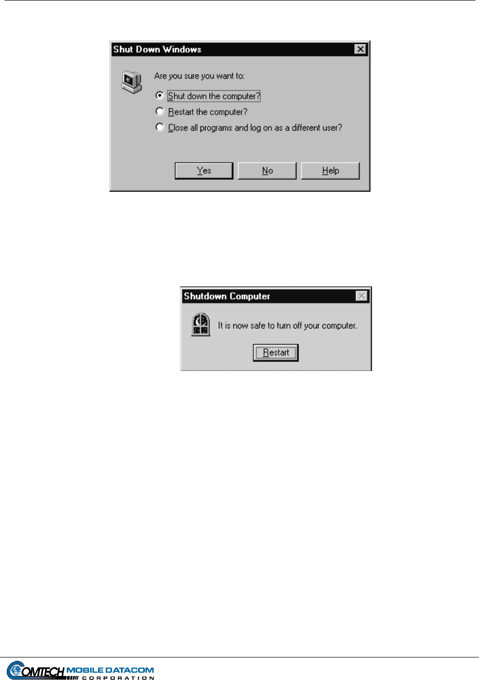
Figure 4-3 Shut Down Window........................................................................................................................... 4-3
Figure 4-4 Shut Down Computer ........................................................................................................................ 4-3
Figure 4-5 V2 A-Kit Control Box ....................................................................................................................... 4-4
Figure 4-6 Security Warning ............................................................................................................................... 4-5
Figure 5-1 The MTS Messenger Icon.................................................................................................................. 5-1
Figure 5-2 Logon Dialog ..................................................................................................................................... 5-1
Figure 5-3 COM Port Select Window ................................................................................................................. 5-2
Figure 5-4 No Response from Terminal.............................................................................................................. 5-2
Figure 5-5 Select PLGR Com Port...................................................................................................................... 5-2
Figure 5-6 Main MTS Messenger Window (Command Reference).................................................................... 5-3
Figure 5-7 Bumper Number in use warning........................................................................................................ 5-4
Figure 5-8 Read Messages Pull Down Menu ...................................................................................................... 5-4
Figure 5-9 New Message..................................................................................................................................... 5-5
Figure 5-10 Read Current Messages ..................................................................................................................... 5-5
Figure 5-11 Read Messages Error Window........................................................................................................... 5-6
Figure 5-12 Review Sent Messages....................................................................................................................... 5-6
Figure 5-13 Send Messages Pull Down Menu ...................................................................................................... 5-7
Figure 5-14 Send Message to a Control Station .................................................................................................... 5-8
Figure 5-15 Send Message to Control Group Window ......................................................................................... 5-9
Figure 5-16 No Control Station Known Message Window..................................................................................5-10
Figure 5-17 No Mobile Known Message Window...............................................................................................5-10
Figure 5-18 No Groups Known Message Window ..............................................................................................5-10
Figure 5-19 Enter Message to Contractor Hub.....................................................................................................5-11
Figure 5-20 Confirm Message to Offline Unit dialog box ...................................................................................5-11
Figure 5-21 Options Pull Down Menu .................................................................................................................5-12
Figure 5-22 Checked Lat-Long Display Menu Option.........................................................................................5-12
Figure 5-23 Lat-Long Display..............................................................................................................................5-13
Figure 5-24 MILGRID Display............................................................................................................................5-13
Figure 5-25 Position Report Rate .........................................................................................................................5-14
Figure 5-26 Print Messages Window ...................................................................................................................5-14
Figure 5-27 Print Error .........................................................................................................................................5-14
Figure 5-28 Print Error Message Window............................................................................................................5-15
Figure 5-29 Review Control Groups ....................................................................................................................5-15
Figure 5-30 Change Bumper Number ..................................................................................................................5-15
Figure 5-31 Clear All Information Warning.........................................................................................................5-16
Figure 6-1 MTS Messenger and Tracerlink Startup ............................................................................................6-1
Figure 6-2 Tracerlink Launcher Icon................................................................................................................... 6-2
Figure 6-3 Tracerlink Vehicle Server Icon.......................................................................................................... 6-2
Figure 6-4 Tracerlink Map Viewer Icon.............................................................................................................. 6-2
Figure 6-5 Tracerlink Vehicle Server Window ................................................................................................... 6-3
Figure 6-6 Tracerlink Map Viewer...................................................................................................................... 6-3

Contract No. DAAB15-99-D-0014 MTS Users Manual Revision: 1.9.1a
Page xi
Figure 6-7 Symbols Representing Mobile Units and Control Stations................................................................ 6-4
Figure 6-8 Right Click Pop Up Menu ................................................................................................................. 6-5
Figure 6-9 Map Showing Measure Distances Function....................................................................................... 6-7
Figure 6-10 Server Vehicle Kit Control Window.................................................................................................. 6-8
Figure 6-11 Kit Bar ............................................................................................................................................... 6-9
Figure 6-12 Selection Tab (Compare with Figure 6-13) ......................................................................................6-10
Figure 6-13 Assignments Tab (Compare with Figure 6-12).................................................................................6-10
Figure 6-14 Autotrack ..........................................................................................................................................6-11
Figure 6-15 Tracing a Vehicle..............................................................................................................................6-12
Figure 6-16 Display Vehicle’s Name ...................................................................................................................6-13
Figure 6-17 Hiding and Showing a Group of Vehicles ........................................................................................6-14
Figure 6-18 Hiding and Showing an Individual Vehicle......................................................................................6-15
Figure 6-19 Hiding and Showing the Names of All Vehicles in a Fleet ..............................................................6-16
Figure 6-20 Hiding and Showing the Position Report Time for a Vehicle...........................................................6-17
Figure 6-21 Hiding and Showing the Position Report for a Fleet of Vehicles .....................................................6-18
Figure 6-22 Centering the Map on a Vehicle .......................................................................................................6-19
Figure 6-23 NIMA Raster Kit Control Window...................................................................................................6-20
Figure 6-24 My Computer Icon............................................................................................................................6-21
Figure 6-25 My Computer Window .....................................................................................................................6-21
Figure 6-26 NIMA CADRG Map Files................................................................................................................6-22
Figure 6-27 TracerLink Map Viewer open with the CADRG Map Files Folder Open ........................................6-23
Figure 6-28 NIMA Raster Kit Control Window Showing the Maps Loading......................................................6-24
Figure 6-29 TracerLink CADRG Map Folder Location in Windows Explorer....................................................6-25
Figure 6-30 Creating a Destination Folder ...........................................................................................................6-27
Figure 6-31 Remove Map Files............................................................................................................................6-28
Figure 7-1 Control Station Menu......................................................................................................................... 7-1
Figure 7-2 Add Control Group Dialog ................................................................................................................ 7-1
Figure 7-3 Selecting several units ....................................................................................................................... 7-2
Figure 7-4 Several units added to the new group ................................................................................................ 7-2
Figure 7-5 Selecting a range of units................................................................................................................... 7-3
Figure 7-6 Range of units added to new group.................................................................................................... 7-3
Figure 7-7 Sent Create Group Request Message................................................................................................. 7-4
Figure 7-8 Added to Group Message .................................................................................................................. 7-4
Figure 7-9 Create Group Failed - Too many groups ...........................................................................................7-4
Figure 7-10 Create Group Not Authorized............................................................................................................ 7-5
Figure 7-11 Modify Control Group Dialog ........................................................................................................... 7-6
Figure 7-12 Select a Control Group to Modify ..................................................................................................... 7-7
Figure 7-13 Sent Modify Group Request Message ...............................................................................................7-8
Figure 7-14 Added to Group Message .................................................................................................................. 7-8
Figure 7-15 Group Not Modified Message ........................................................................................................... 7-8
Figure 7-16 Modification of Group Not Authorized ............................................................................................. 7-9
Figure 7-17 Delete Control Group........................................................................................................................7-10
Figure 7-18 Confirm Group Deletion...................................................................................................................7-10
Figure 7-19 Group Successfully Deleted..............................................................................................................7-11
Figure 7-20 Delete Request Failed .......................................................................................................................7-11
Figure 7-21 Delete Request Denied......................................................................................................................7-11
Figure 7-22 Delete Group Restricted....................................................................................................................7-12
Figure 7-23 Delete Group Not Authorized...........................................................................................................7-12
Figure 7-24 Promote Mobile to CS Dialog Box...................................................................................................7-13
Figure 7-25 Promotion Confirmation ...................................................................................................................7-13
Figure 7-26 Promotion Request Failed.................................................................................................................7-14
Figure 7-27 Demote CS to Mobile Dialog Box....................................................................................................7-14
Figure 7-28 Demotion Confirmation....................................................................................................................7-15
Figure 7-29 Demotion Request Failed..................................................................................................................7-15

Contract No. DAAB15-99-D-0014 MTS Users Manual Revision: 1.9.1a
Page xii
Figure 7-30 Release Bumper Number Dialog ......................................................................................................7-16
Figure 7-31 Release Bumper Number Request Sent ............................................................................................7-16
Figure 7-32 Unit not in Group Warning...............................................................................................................7-17
Figure 7-33 Bumper Number Successfully Released ...........................................................................................7-17
Figure 7-34 The Help Menu .................................................................................................................................7-18
Figure 7-35 About MTS Messenger.....................................................................................................................7-18
Figure 8-1 No Response from Terminal Error Message...................................................................................... 8-1
Figure 9-1 Help Menu ......................................................................................................................................... 9-1
Figure 9-2 Sample Debug Log ............................................................................................................................ 9-2
Figure 9-3 LEDs on Transceiver ......................................................................................................................... 9-3
Figure 9-4 Vehicle Server Window – COMM InActive ..................................................................................... 9-5
Figure 9-5 Check Status of Vehicle via MTS Messenger.................................................................................... 9-6
Figure 9-6 Server Vehicle Kit Control – Delete a Server....................................................................................9-7
Figure 9-7 Server Vehicle Kit Control – Connect to Server................................................................................ 9-7
Figure 9-8 Server Vehicle Kit Control –New Server Connection – Local .......................................................... 9-8
Figure 9-9 Server Vehicle Kit Control Window Server Tab .......................................................................... 9-9
Figure 9-10 Connecting A Vehicle or Group ........................................................................................................ 9-9
Figure 13-1 Enter Group Message Dialog Box ....................................................................................................13-1
Figure 14-1 V2 computer mount (with V2 Computer installed) inside FMTV cab .............................................14-1
Figure 14-2 V2 Control Box mounted inside FMTV cab.....................................................................................14-1
Figure 14-3 V2 computer mount (without V2 Computer) inside HEMTT cab ....................................................14-2
Figure 14-4 V2 computer mount (without V2 Computer installed) inside HET cab............................................14-2
Figure 14-5 V2 Computer Mount inside HMMWV.............................................................................................14-3
Figure 14-6 V2 Computer Mount (without V2 Computer installed) inside PLS..................................................14-3
Figure 14-7 Transceiver mount (without MT2011 transceiver installed) on top of the FMTV cab .....................14-4
Figure 14-8 Transceiver mount (without MT 2010 transceiver installed) on top of the HEMTT cab .................14-4
Figure 14-9 Transceiver mount (without MT 2010 transceiver installed) on top of the HET cab .......................14-5
Figure 14-10 Transceiver mount (with MT 2011 transceiver installed) on the back of the HMMWV cab.......14-5
Figure 14-11 Transceiver mount (with MT 2011 transceiver installed) on top of the PLS cab.........................14-6

Contract No. DAAB15-99-D-0014 MTS Users Manual Revision: 1.9.1a
Page 1-1
1. Safety
1.1 General Installation Information
The Movement Tracking System (MTS) described in this document will be installed in
many standard Army vehicles including:
FMTV (Appendix 14.1)
HEMTT (Appendix 14-2)
HET (Appendix 14-3)
HMMWV (Appendix 14-4)
PLS (Appendix 14-5)
900 series 5-ton trucks
There are two parts to the MTS installation:
(1) The A-Kit, which is permanently installed in the vehicle. The A-Kit has three
primary parts:
(a) The control box and ruggedized computer mount inside the vehicle, (see
Appendix 15.1.1 – 15.1.7);
(b) The transceiver mount which sits outside the vehicle (see Appendix 15.2.1 –
15.2.5);
(c) The cabling that connects 1.a and 1.b.
(2) The B-Kit is the equipment the user (operator) installs into the A-Kit.
Both kits can pose safety issues if they are not handled properly.
NOTE: In this section of the manual a ““ signifies a warning.
1.2 Health Hazards
MTS is designed to function without injuring the soldier. However proper installation
and operation are necessary to prevent soldier injuries.
1.2.1 Driving Operation
MTS will be operated in a vehicle. MTS provides improved visibility and
communications for transporters.

Contract No. DAAB15-99-D-0014 MTS Users Manual Revision: 1.9.1a
Page 1-2
WARNING: The driver should never operate the MTS computer while the
vehicle is moving. Only a passenger should operate the MTS computer in a
moving vehicle. Driver operation of the MTS computer in a moving vehicle
could cause an accident injuring the driver and passenger(s) as well as
damaging the vehicle.
1.2.2 Bumping Injuries
The MTS A-Kits are installed so that they do not interface with normal vehicle
operation. Where possible, MTS hardware has been placed where soldiers will not
bang, bump, or otherwise run into the equipment. However soldiers should heed the
following warnings:
WARNING: Use of engineer tape (or some other medium) to mark the
equipment’s location is advised if the equipment appears to affect a soldier’s
normal interaction with the vehicle.
WARNING: Soldiers should look and proceed with caution when entering
all tactical vehicles.
1.2.3 Repetitive Stress Injuries
Repetitive stress injuries are caused by frequent and near constant use of a piece of
equipment. Repetitive stress injuries are possible when working with computer
equipment.
WARNING: The ruggedized computer (V2) has a small 6.5” screen and a
small keyboard. The screen can cause eyestrain if used for extended periods
without breaks. It is recommended that soldiers only use the computer when
necessary to prevent repetitive stress injuries. Soldiers should use the
computer when sending operational messages and to view the map and not
for playing games or sending personal messages.
1.2.4 Electric Shock Injuries
MTS is a low voltage, low amperage system which under normal conditions should
pose very little threat of electric shock. However, soldiers should take necessary
precautions when working with electrical equipment:
WARNING: Do not be misled by the term “low voltage.” Potentials as low
as 50 volts may cause death under certain conditions.

Contract No. DAAB15-99-D-0014 MTS Users Manual Revision: 1.9.1a
Page 1-3
WARNING: Failure to power the Control Station from a grounded 110/220
AC outlet may result in serious injury (see section on Control Station
Installation).
WARNING: Never touch an exposed wire. If a piece of equipment
appears damaged do not touch it.
1.2.5 Procedures for Treating Victims of Electrical Shock:
(1) Do not try to pull or grab the individual.
(2) If possible, turn off the electrical power.
(3) If you cannot turn off the electrical power, pull, push or lift the person to
safety using a dry wooden pole, or dry rope or some other insulated material.
(4) Notify your COC or send request for assistance ASAP.
(5) After the injured person is free of contact with the source of electrical shock,
move the person a short distance away and immediately begin appropriate
buddy aid (as required).
(6) Monitor and comfort casualty until help arrives or evacuate to nearest aid
station as needed.
1.2.6 Radio Frequency Energy
The Movement Tracking System incorporates a radio transmitter, receiver, and
antenna (the MT2011 or MT2010) that receive and send radio frequency (RF) energy.
This energy is transmitted and received using satellites orbiting the earth.
The design of the MT2011 and MT2010 units complies with the updated (1992)
ANSI standard for safe levels of human exposure to RF energy. This is published
under the auspices of the American National Standards Institute and the Institute of
Electrical and Electronics Engineers, and is called “ANSI/IEEE C95.1-1992, Safety
Levels with Respect to Human Exposure to Radio Frequency Electromagnetic Fields,
3kHz to 300GHz.
The minimum separation distance between the MT2011 or MT2010 antenna and the
user or bystander is 40cm (16 inches). The antenna is designed to mount on the top
surface of a land vehicle, ship, or aircraft. It is inherent in the mounting configuration
and use of the MT2011 or MT2010 antenna that the minimum separation distance be
maintained or exceeded under all operational conditions.

Contract No. DAAB15-99-D-0014 MTS Users Manual Revision: 1.9.1a
Page 1-4
WARNING: Soldiers must maintain the minimum safe distance from
Functioning Antenna at all times!

Contract No. DAAB15-99-D-0014 MTS Users Manual Revision: 1.9.1a
Page 2-1
2. Concept of Operations
2.1 Introduction
2.1.1 Overview
Movement Tracking System (MTS) is a global satellite communications system that
provides text messaging and vehicle tracking capabilities for the U.S. Army. It
allows a commander to determine where his vehicles are, what their status is, and to
communicate with them in near real-time.
Because the system is satellite-based, telephone lines are not required for in-theater
operations, and unlike line-of-sight radios, repeater stations are never necessary. As
long as the MTS satellite transceiver has an unhindered view of the satellite, it will be
able to communicate with other on-line MTS systems.
The three key features of the Movement Tracking System developed by Comtech
Mobile Datacom (CMDC) are its ability to use a variety of in-orbit commercial
satellites, it’s near real-time communications speed, and its security features.
(1) Compatibility with Multiple Commercial Satellites
The MTS system can use many different types of commercial satellites. As a
result it can interact with a satellite and operate in any region of the world.
(2) Real-time Messaging Speeds
A message is typically transmitted from one MTS-equipped vehicle to another in
under 10 seconds.
(3) Information Security
The waveform used by Comtech Mobile Datacom’s MTS is spread spectrum and
exhibits a low probability of detection by unauthorized listening devices. In
addition, the data is triple encrypted end-to-end to further prevent eavesdropping.
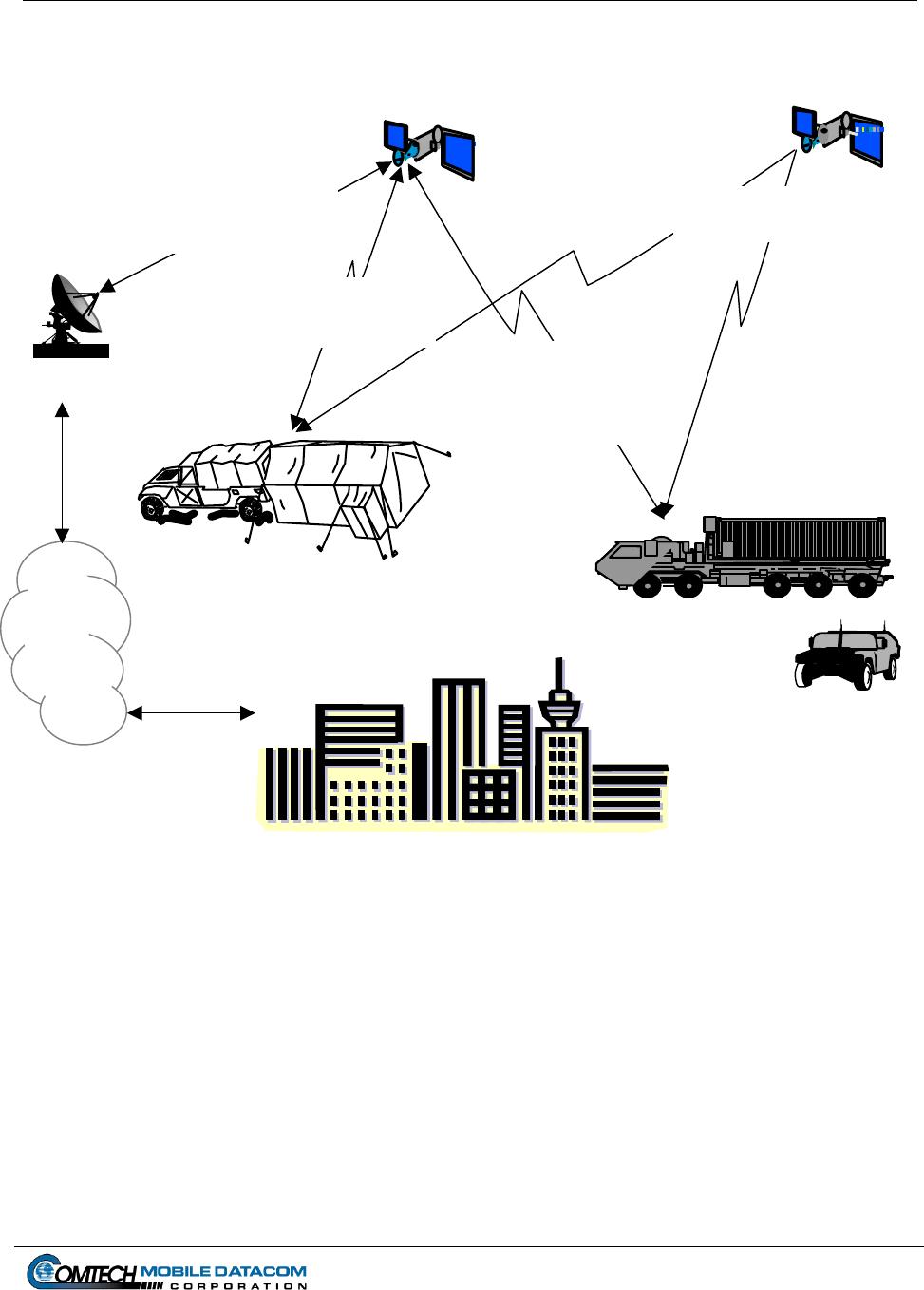
2.1.2 Message Routing Architecture
In normal operations, when an MTS user sends a message, the data packet is
transmitted to the satellite, which relays it back down to the Comtech Mobile
Datacom ground station switch. The switch sends the data packet back over the
satellite to its intended destination. When the message is received, the destination
returns an acknowledgement over the satellite to the switch, which forwards it to the
message sender, verifying message delivery.
Contract No. DAAB15-99-D-0014 MTS Users Manual Revision: 1.9.1a
GPS Satellite
Constellation
Page 2-2
Communication
Satellite
Gateway/Network
Management Center
routes messages sent via
communications
satellites
GPS Position is sent to
all units
TOC sends / receives
messages to / from
Mobile Units
GPS Position &
Messages are sent
/received to/from
mobiles, the TOC & fixed
sites
Gateway
Theater Operations Center
with MTS Control Station Mobile Units
Internet
Fixed Sites
Figure 2-1 Concept of Operations

Contract No. DAAB15-99-D-0014 MTS Users Manual Revision: 1.9.1a
Page 2-3
2.1.3 User Systems
The Movement Tracking System is made up of two configurations – the Control
Station, and the V2 Mobile Unit.
(1) The Control Station provides command functionality for the MTS, and is
typically operated from a mobile headquarters, such as a TOC. The Control
Station operates independent of phone lines or Internet connections. A Control
Station operator is responsible for coordinating vehicle movements using text
messaging and theater map displays of MTS-equipped vehicles. The Control
Station configuration consists of a laptop computer with CD-ROM drive for
loading maps, a satellite transceiver with 100-foot cable, a Precision Lightweight
GPS Receiver (PLGR) and a portable printer.
(2) The V2 Mobile Unit is designated for permanent installation in a vehicle and
consists of a satellite transceiver and ruggedized computer with appropriate
cabling and a Precision Lightweight GPS Receiver (PLGR). It provides text
messaging and maps of MTS-equipped vehicles including itself.
Each configuration comes pre-loaded with MTS Software to include the MTS Messager
and TracerLink Mapping application.
2.2 About This Manual
This manual describes the installation and operation of the two MTS configurations. It
also provides training information for MTS operators. The MTS configurations
described in this manual are called B-Kits. The mounting hardware and wiring needed to
install the B-Kits in each type of vehicle is called an A-Kit. A-Kits are unique to each
type of vehicle. This manual does not cover the A-Kit installation. A diagram of the A-
Kits is available in the Appendix of this document. This manual describes how to
connect the B-Kit to the A-Kit and provides rough sketches of portions of the A-Kit to
assist in basic hookup.
Contract No. DAAB15-99-D-0014 MTS Users Manual Revision: 1.9.1a
Page 3-1
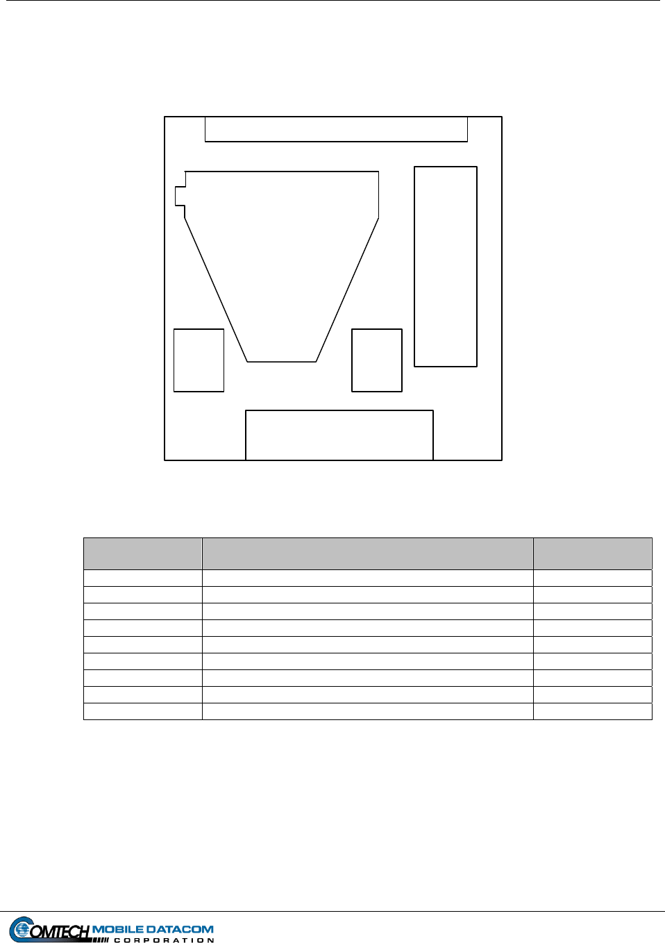
3. Installation and Setup
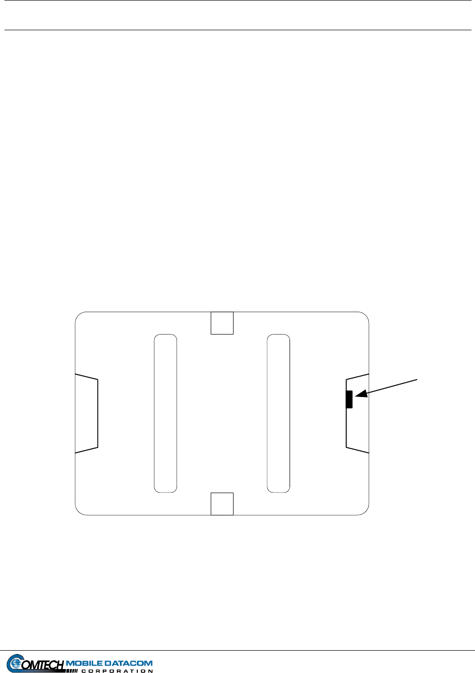
3.1 Opening a Transit Case
All MTS components when not in use should be stored within the system transit case.
The transit case protects MTS components during shipment and storage. To open the
transit case:
(1) Place the case with the handles down.
(2) Unfasten the butterfly clips on the outside of the case.
(3) Open the case.
NOTE: If the case does not open easily, verify that the four butterfly clips are
unfastened. If the butterfly clips are all unfastened and the case still does not open,
depress the pressure release valve on the side of the transit case.
Transit Case (Top View)
Pressure
Release
Valve
Figure 3-1 Transit Case (Top View)
Contract No. DAAB15-99-D-0014 MTS Users Manual Revision: 1.9.1a
Page 3-2
3.2 Installing the Control Station Configuration
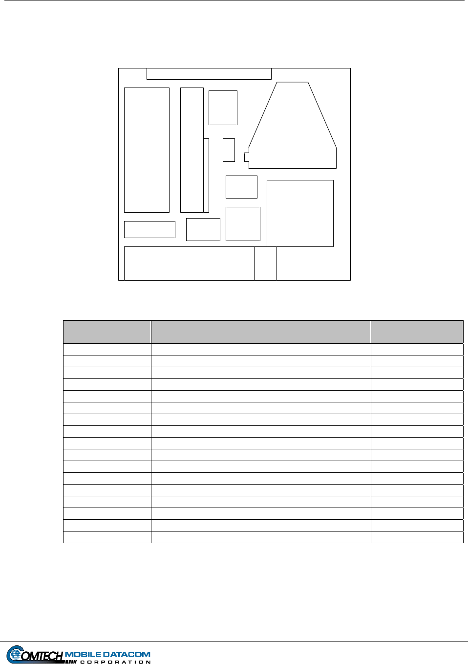
3.2.1 Equipment list
12
10
4 5
3
6
7
9
11
2
8
1
Figure 3-2 Control Station Transit Case Contents
MTS Part No Item Description Transit Case
Location
MTS-TERM-002 Transceiver (Satellite Modem) 1
MTS-COV-01 Camouflage Cover 1
MTS-MAN-01 MTS Manual 2
PLGR 3
MTS-CS-06 Printer 4
MTS-CS-01 Laptop Computer 5
MTS-CS-05A Port Expander 5
MTS-CS-09A Power Adapter, Printer 6
MTS-CS-10 Color Cartridge, Printer 8
MTS-CS-03 Power Adapter, Laptop 9
MTS-CS-02 Battery, Spare, Laptop 10
MTS-CS-04A 100’ Cable, Data, Power 11
MTS-CS-05B Port Expander Cable 12
MTS-CS-11 Cable, Data, (Control Box to Computer) 12
MTS-CS-08 10’ Cable, Data, Printer 12
MTS-CS-09B Power Cable, Printer 12
PLGR External Antenna 12
Contract No. DAAB15-99-D-0014 MTS Users Manual Revision: 1.9.1a
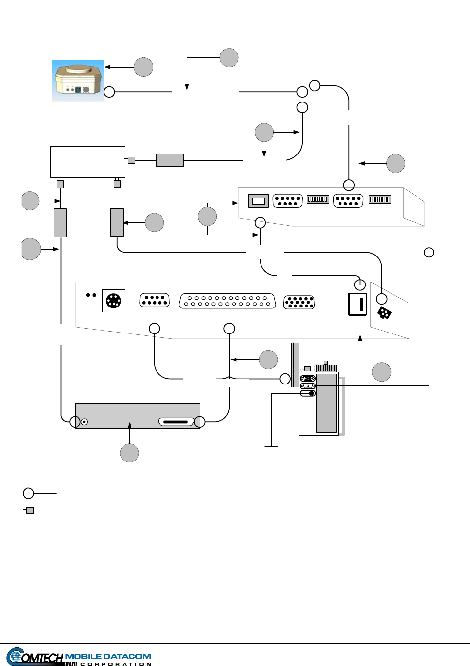
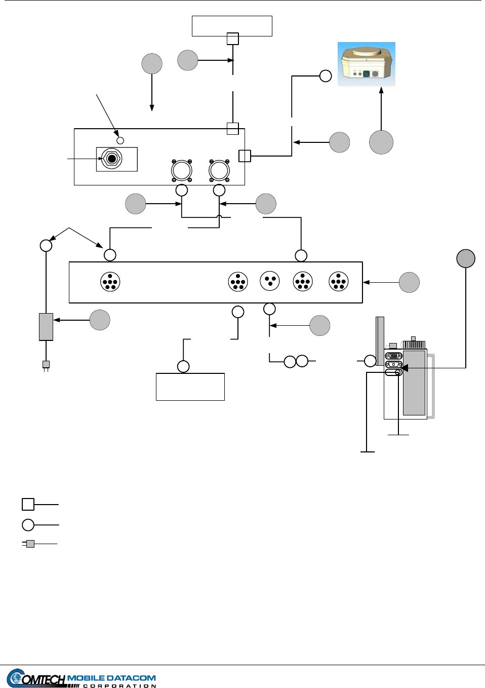
Page 3-3
Laptop (Rear View)
15 Pin Male
USB
External
Mouse Port
COM 1
9 Pin Male
RS232
Printer Port
DB25
25 Pin Female
Printer
(Rear View) PLGR Cable connects to
the top port of the PLGR
NOTE: This diagram is not to scale.
External Power
AC
RS422
Data Cable
CS-
01
CS-
04B
CS-
03
AC Power Cable
100' Cable (Power & Data)
CS-
06
CS-
09A
CS-
11
CS-
08
Key to Understanding Connections
TERM
-001
CS-
05
CS-
09B
PLGR Cable
USB
Cable
Power Adapter
Laptop
Power
Adapter
Printer
Printer Cable
PLGR
(Rear View)
Port Expander
(Rear View)
Dip Switch Dip Switch
9 Pin Male 9 Pin MaleUSB
Power
Laptop
(Side View)
External
Antenna
V a/c
CS-
04A
Cable end has two
connectors for power
and data.
Cable with circle end represents
operator made connections
Cable with a standard U.S. wall plug
MT-2011
Figure 3-3 Installation of Control Station Hardware

Contract No. DAAB15-99-D-0014 MTS Users Manual Revision: 1.9.1a
Page 3-4
3.2.2 Control Station (CS) Component Installation (See Figure 3-3)
NOTE: Numbers in square brackets [#] denote part numbers in Figure 3-3.
CAUTION: Do not force any connectors. Doing so may damage pins.
3.2.2.1 CS Transceiver (MT 2011) installation
(1) Place the MT 2011 [TERM-001] in a location with a clear view of the
sky, avoiding blockage or shadowing from trees and buildings.
(2) Connect the 100-foot power/data cable [CS-04B] from the side of the
transceiver to the RS-422 cable [CS-11] and the power cable [CS-4A].
3.2.2.2 CS Laptop installation
(1) Using the USB Cable [CS-05B] connect the USB port on the laptop
[CS-01] to the USB port on the port expander [CS-05A]. The Port
Expander should already be fastened to the laptop with Velcro. If it
has become detached, refasten the port expander to the laptop.
(2) Using the RS422 data cable [CS-11], connect the port expander [CS-
05A] to the 100’ cable [CS-04B]. Connect one end of the cable to the
9 Pin Male port labeled COM3 on the port expander device [CS-05A]
and connect the other end to the RS422 port on the 100’ cable [CS-
04B].
(3) Connect the laptop power adapter [CS-03] to an AC power source.
The power port on the laptop can be found on left side rear of the
laptop. It does not need to be connected to the same AC power source
as the Transceiver.
NOTE: The laptop can work on internal batteries for up to four hours per
battery.
3.2.2.3 CS Printer installation
(1) Using the printer cable [CS-08] connect the printer to the laptop. One
end of the cable will have a connector with a set of 25 pins; connect
this end to the DB25 port (the large 25 pin port) on the rear of the
laptop. Connect the other end of the cable to the printer.
(2) Using the printer power adapter [CS-09A & CS-09B] and printer cable
connect the printer to an AC power supply.
Contract No. DAAB15-99-D-0014 MTS Users Manual Revision: 1.9.1a
Page 3-5
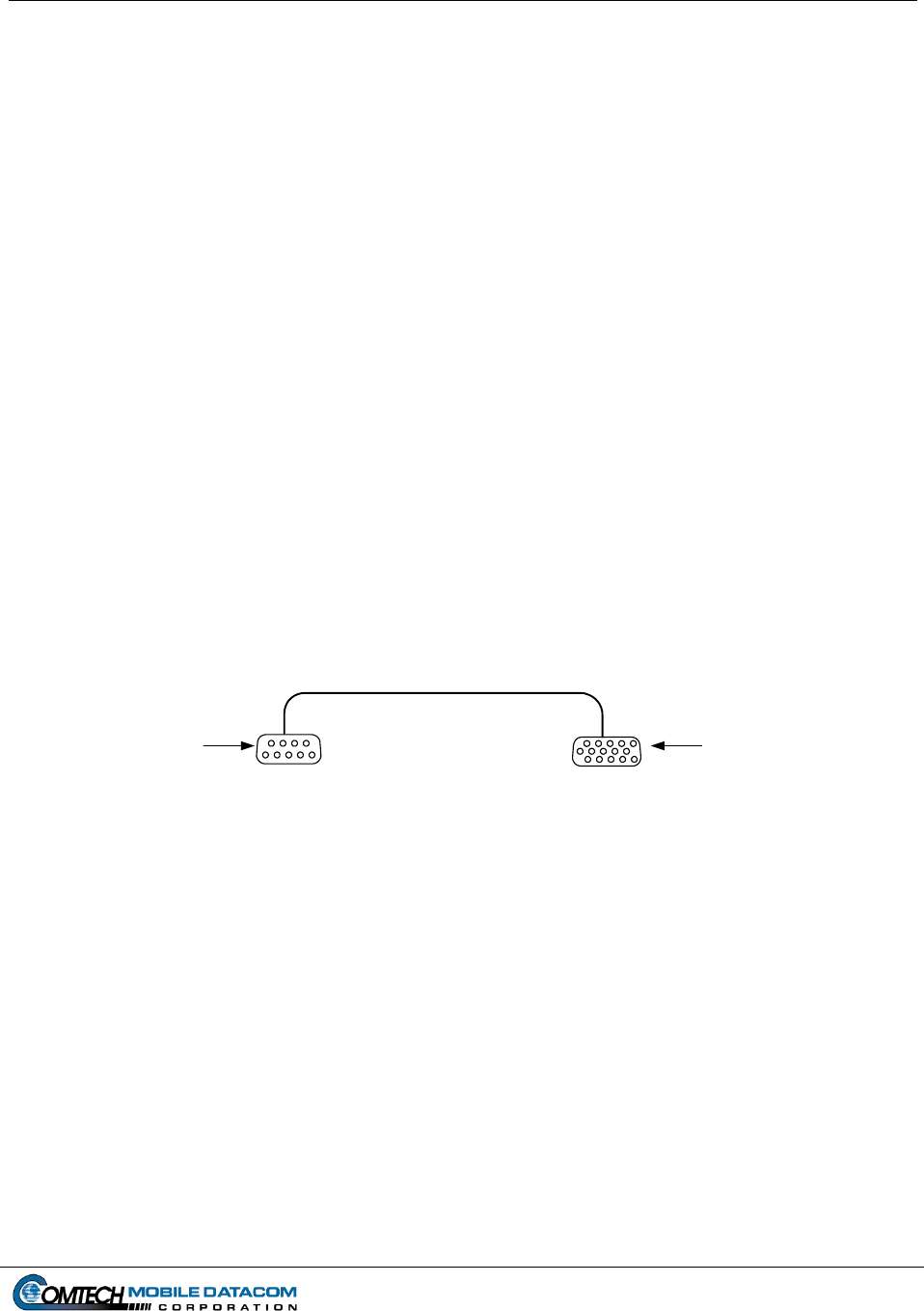
3.2.2.4 CS PLGR installation
(1) Connect the 9 pin female RS232 port connector of the PLGR cable to
COM1 port on the laptop computer. COM1 is the only RS232 on the
laptop. Figure 3-4 shows the two connectors on a standard PLGR
cable.
(2) Connect the 15 pin female connector of the PLGR cable to the top port
of the PLGR. All ports on the PLGR can be found on the back of the
device.
(3) Connect the remote PLGR antenna cable to the second port of the
PLGR. Connect the remote PLGR “hockey puck” antenna to the
antenna cable.
(4) Connect PLGR AC power adapter cable to the third PLGR port. Plug
the PLGR power supply into the wall outlet making sure the voltage
selector is in the proper position (110/220).
NOTE: The PLGR cable and PLGR are not included in the standard Control
Station package.
15 Pin
Female
9 Pin
Female
RS232
Standard PLGR Cable
Connects to
COM1 port (9 pin)
of Control Station
Laptop
Connects to top port
(15 pin) of PLGR
Figure 3-4 Control Station PLGR Cable Setup
Contract No. DAAB15-99-D-0014 MTS Users Manual Revision: 1.9.1a
Page 3-6
3.3 Installing the V2 Configuration
3.3.1 Equipment list
1
4
3
6
5
2
Figure 3-5 V2 Transit Case Contents
MTS Part No Item Description Transit Case
Location
MTS-TERM-002 Transceiver (Satellite Modem) 1
MTS-COV-01 Camouflage Cover 1
MTS-MAN-01 MTS Manual 2
PLGR 3
MTS-V2-01 Ruggedized Computer 4
MTS-V2-06 Cable, Data, PLGR 5
PLGR External Antenna 5
MTS-V2-02 Cable, Data 6
MTS-V2-03 Cable, Power 6
Contract No. DAAB15-99-D-0014 MTS Users Manual Revision: 1.9.1a
A-Kit Items
A-Kit items correspond to circled numbers in diagram, and are pre-
installed in the vehicle. They do not reflect actual part numbers.
A-1. Control Box
A-2. MT-2011 Power and Data Cable
A-3. Vehicle Power Cable (Operators should not touch this cable).
Universal AC Power
Adapter
Allows user to plug
computer into a standard
wall jack when the
computer is not installed in
a vehicle
Connector
Computer
Power
Connector
Computer
RS422
Indicator - Backup Power
Power in User LED "Green"
MTS Control
On/Off Switch
Vehicle Power
Connects to back
of Control Box
A-Kit Control Box
Power Cable
Data Cable
Power/ Data Cable
Connects to
J1 Port on
the Laptop
Ruggedized Computer
Bottom View
Power Keyboard
COM 1
RS232
COM 2
RS422
COM 3
RS422
Keyboard
& Mouse
NOTE: This diagram is not to scale.
Cable with square end represents fixed
connections
Cable with circle end represents
operator made connections
Key to Understanding Connections
Cable with a standard U.S. wall plug
Keyboard
Cable
(Pre-Installed) PLGR
Adapter
V2-
01
TERM
-001
V2-
02
V2-
03
V2-
04 V2-
06
A-1 A-3
A-2
Page 3-7
PLGR
(Rear View)
PLGR
Cable
(Note included
in transit case)
The PLGR cable connects to the ruggedized
computer via the PLGR adapter (V2-06).
V bat
Ground Strap
MT-2011
External
A
ntenna
Figure 3-6 Installation of V2 Hardware

Contract No. DAAB15-99-D-0014 MTS Users Manual Revision: 1.9.1a
Page 3-8
3.3.2 V2 Component Installation
NOTE: These installation instructions assume that the vehicle has already been
configured with an A-Kit. Numbers in square brackets [#] denote part numbers in
Figure 3-6.
CAUTION: Do not force connections. Doing so may damage pins.
3.3.2.1 V2 Transceiver (MT 2010/MT 2011) installation
(1) Attach the transceiver [TERM-001] to the A-Kit mounting bracket on
the roof of the vehicle.
(2) Attach the security lanyard found on the mounting bracket to the
transceiver [TERM-001].
(3) Connect the A-Kit power/data cable [A-2] to the transceiver. The
power/data cable is part of the A-Kit. It starts at the Control Box [A-
1] and ends with a connector that attaches to the transceiver. When the
transceiver is not mounted on the vehicle, the power/data cable
connector should be securely stowed on the A-Kit mounting bracket to
protect the cable connector.
3.3.2.2 V2 Ruggedized computer installation to the A-Kit
(1) Attach the ruggedized computer [V2-01] to the A-Kit mounting
bracket located inside vehicle.
(2) Connect the data cable [V2-03] to COM 2 that is on the bottom side of
the computer to the RS422 port on the A-Kit’s Control Box [A-1].
(3) Using the computer power cable [V2-02] connect the power port on
the computer to the power port on the A-Kit’s Control Box [A-1].
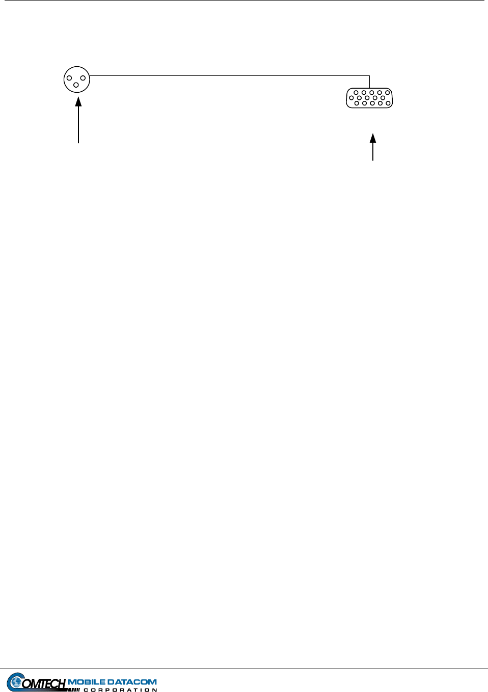
3.3.2.3 V2 PLGR installation
(1) Connect the military connector on the PLGR adapter cable [V2-06] to
the ruggedized computer’s [V2-01] serial port COM 1. Figure 3-7
shows the connectors on the PLGR adapter cable [V2-06].
(2) Connect the 9 pin male connector on the PLGR adapter cable [V2-06]
to the 9 pin female connector on the PLGR cable.
(3) Connect the 15 pin female connector of the PLGR cable to the top port
of the PLGR. All ports on the PLGR can be found on the back of the
device.
Contract No. DAAB15-99-D-0014 MTS Users Manual Revision: 1.9.1a
Page 3-9
Connects to top port
(15 pin) of PLGR
15 Pin
Female
Standard PLGR Cable
PLGR Adapter (V2-06)
Connects to J3
port on bottom of
the ruggedized
computer
Figure 3-7 V2 PLGR Adapter connection to Standard PLGR Cable

Contract No. DAAB15-99-D-0014 MTS Users Manual Revision: 1.9.1a
Page 4-1
4. Power On/Power Off Procedures
4.1 Control Station Power On/Power Off Procedures
4.1.1 Understanding the Control Station Configuration’s Power Source
(1) The Control Station is designed to operate in a fixed location or in a contingency
location such as a Tactical Operations Center (TOC). The Control Station laptop
and the transceiver (MT2011) use external power and must be plugged into a
power socket. The transceiver is powered on when it is plugged in, and its LEDs
will light up.
4.1.2 Control Station Laptop Power On
(2) Press the power switch on the laptop computer. Wait for the computer to
load/initialize software.
(3) When prompted, press CTRL-ALT-DEL to login.
(4) Eventually you will see a security window similar to the one in Figure 4-1. Read
over the text in the window, and click OK if you agree to the terms.
Attention
THIS IS A DOD COMPUTER SYSTEM. BEFORE PROCESSING CLASSIFIED
INFORMATION, CHECK THE SECURITY ACCREDITATION LEVEL OF THIS SYSTEM. DO
NOT PROCESS, STORE OR TRANSMIT INFORMATION CLASSIFIED ABOVE THE
ACCREDITATION LEVEL OF THIS SYSTEM. THIS COMPUTER SYSTEM, INCLUDING
ALL RELATED EQUIPMENT, NETWORKS AND NETWORK DEVICES (INCLUDING
INTERNET ACCESS) ARE PROVIDED ONLY FOR AUTHORIZED U.S. GOVERNMENT
USE. DOD COMPUTER SYSTEMS MAY MONITORED FOR ALL LAWFUL PURPOSES,
INCLUDING TO ENSURE THEIR USE IS AUTHORIZED, FOR MANAGEMENT OF THE
SYSTEM, TO FACILITATE PROTECTION AGAINST UNAUTHORIZED ACCESS, AND TO
VERIFY SECURITY PROCEDURES, SURVIVABILITY, AND OPERATIONAL SECURITY.
MONITORING INCLUDES BUT IS NOT LIMITED TO, ACTIVE ATTACKS BY AUTHORIZED
DOD ENTITIES OT TEST OR VERIFY SECURITY OF THIS SYSTEM. DURING
MONITORING, INFORMATION MAY BE EXAMINED, RECORDED, COPIED AND USED
FOR AUTHORIZED PURPOSES. ALL INFORMATION, INCLUDING PERSONAL
INFORMATION, PLACED ON OR SENT OVER THIS SYSTEM MAY BE MONITORED. USE
OF THIS DOD COMPUTER SYSTEM, AUTHORIZED OR UNAUTHORIZED, CONSTITUTES
CONSENT TO MONITORING. UNAUTHORIZED USE OF THIS DOD COMPUTER SYSTEM
MAY SUBJECT YOU TO CRIMINAL PROSECUTION. EVIDENCE OF UNAUTHORIZED
USE COLLECTED DURING MONITORING MAY BE USED FOR ADMINISTRATIVE,
CRIMINAL, OR OTHER ADVERSE ACTION. USE OF THIS SYSTEM CONSTITUTES
CONSENT TO MONITORING FOR ALL LAWFUL PURPOSES.
OK
Figure 4-1 Security Warning
Contract No. DAAB15-99-D-0014 MTS Users Manual Revision: 1.9.1a
Page 4-2
(5) Enter username and password, and then click OK. The Windows desktop should
contain the MTS Messenger and Tracerlink icons. Start the MTS Messenger
software to see if the cables to the computer are correctly attached. Go to Section
5 of this manual to learn how to start the software.
4.1.3 Control Station Printer – Power On
The Control Station Printer can draw power from two sources, an internal battery or
an AC wall outlet. Printer will power on when the top cover is opened, if it does not,
press the power button. To turn the printer off, press the power button located on top
of the printer. It is the button in the center, of the three available buttons.
(1) To turn the printer on, simply lift up the top cover or push the power button once.
The small indicator light (in the center of the top of the printer) will illuminate if
the printer is on.
4.1.4 Control Station Laptop Power Off
CAUTION: Improper shut down of system may result in data loss.
(1) Close all open applications (MTS Messenger, Tracerlink Vehicle Server,
Tracerlink Map Viewer).
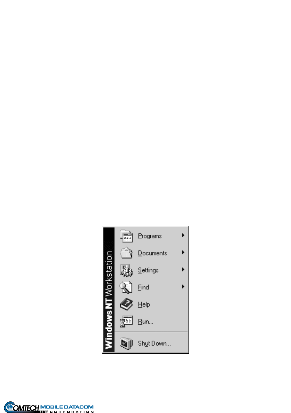
(2) Click the Start button in bottom left corner of the screen (see Figure 4-2).
Figure 4-2 Windows Start Button
Contract No. DAAB15-99-D-0014 MTS Users Manual Revision: 1.9.1a
Page 4-3
(3) Select the Shut Down option. A window as in Figure 4-3 should pop-up.
Figure 4-3 Shut Down Window
(4) Select Shut Down and then click the Yes button (see Figure 4-3).
(5) When the following window appears (see Figure 4-4):
Figure 4-4 Shut Down Computer
(6) Press the Power ON/OFF button on the laptop.
4.1.5 Control Station Printer – Power Off
To turn the printer off, simply push the power button again. The small indicator light
(above the power button) will go out.
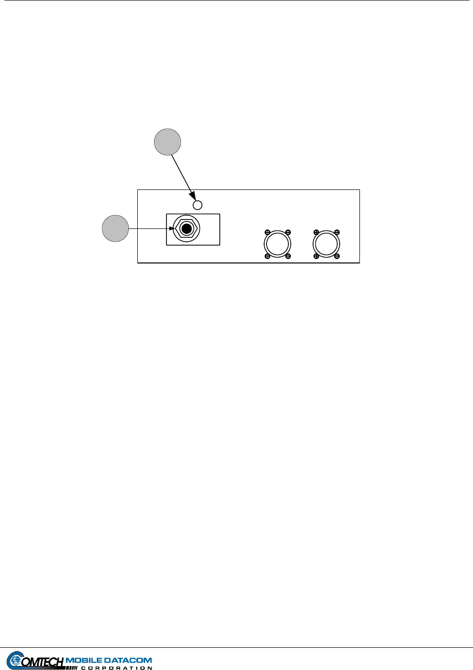
Contract No. DAAB15-99-D-0014 MTS Users Manual Revision: 1.9.1a
Page 4-4
4.2 V2 Configuration Power On/Power Off Procedures
4.2.1 Understanding the V2 Configuration’s Power Source
The V2 is designed to operate in a vehicle. The V2 is designed to operate with
vehicle power. The transceiver and the ruggedized computer use a control box to
draw power from the vehicle (see Figure 4-5).
Connector
Computer
Power
Connector
Computer
RS422
V2 A-Kit Control Box
1
2
1. Control Box Power Switch
2. Green LED Indicator
Figure 4-5 V2 A-Kit Control Box
If the vehicle is on, the V2 Configuration will draw power from the vehicle. If the
Unit is drawing power the green LED will light up.
4.2.2 V2 Control Box – Power On
To turn on the V2 Control Box, first make sure that the vehicle is at least running on
battery power. Flip the Power Switch (item 1 on Figure 4-5) to ON. If connected
correctly, the LED lights on the transceiver (MT 2010/MT 2011) will illuminate.
4.2.3 V2 Ruggedized Computer – Power On
(1) The computer will power on automatically when the Control Box is turned on.
Wait for the computer to load/initialize software.
(2) When prompted, press CTRL-ALT-DEL to login.
(3) Eventually you will see a security window similar to the one in Figure 4-6. Read
over the text in the window, and click OK if you agree to the terms.
Contract No. DAAB15-99-D-0014 MTS Users Manual Revision: 1.9.1a
Page 4-5
Attention
THIS IS A DOD COMPUTER SYSTEM. BEFORE PROCESSING CLASSIFIED
INFORMATION, CHECK THE SECURITY ACCREDITATION LEVEL OF THIS SYSTEM. DO
NOT PROCESS, STORE OR TRANSMIT INFORMATION CLASSIFIED ABOVE THE
ACCREDITATION LEVEL OF THIS SYSTEM. THIS COMPUTER SYSTEM, INCLUDING
ALL RELATED EQUIPMENT, NETWORKS AND NETWORK DEVICES (INCLUDING
INTERNET ACCESS) ARE PROVIDED ONLY FOR AUTHORIZED U.S. GOVERNMENT
USE. DOD COMPUTER SYSTEMS MAY MONITORED FOR ALL LAWFUL PURPOSES,
INCLUDING TO ENSURE THEIR USE IS AUTHORIZED, FOR MANAGEMENT OF THE
SYSTEM, TO FACILITATE PROTECTION AGAINST UNAUTHORIZED ACCESS, AND TO
VERIFY SECURITY PROCEDURES, SURVIVABILITY, AND OPERATIONAL SECURITY.
MONITORING INCLUDES BUT IS NOT LIMITED TO, ACTIVE ATTACKS BY AUTHORIZED
DOD ENTITIES OT TEST OR VERIFY SECURITY OF THIS SYSTEM. DURING
MONITORING, INFORMATION MAY BE EXAMINED, RECORDED, COPIED AND USED
FOR AUTHORIZED PURPOSES. ALL INFORMATION, INCLUDING PERSONAL
INFORMATION, PLACED ON OR SENT OVER THIS SYSTEM MAY BE MONITORED. USE
OF THIS DOD COMPUTER SYSTEM, AUTHORIZED OR UNAUTHORIZED, CONSTITUTES
CONSENT TO MONITORING. UNAUTHORIZED USE OF THIS DOD COMPUTER SYSTEM
MAY SUBJECT YOU TO CRIMINAL PROSECUTION. EVIDENCE OF UNAUTHORIZED
USE COLLECTED DURING MONITORING MAY BE USED FOR ADMINISTRATIVE,
CRIMINAL, OR OTHER ADVERSE ACTION. USE OF THIS SYSTEM CONSTITUTES
CONSENT TO MONITORING FOR ALL LAWFUL PURPOSES.
OK
Figure 4-6 Security Warning
(4) Enter username and password, and then click OK. The Windows desktop should
contain the MTS Messenger and Tracerlink icons. Start the MTS Messenger
software to see if the cables to the computer are correctly attached. Go to Section
5 of this manual to learn how to start the software.
4.2.4 V2 Power Off
CAUTION: Improper shut down of system may result in data loss.
(1) Close all open applications (MTS Messenger, Tracerlink Vehicle Server,
Tracerlink Map Viewer).
(2) Click the Start button in bottom left corner of the screen.
(3) Select the Shut Down option.
(4) Select Shut Down and then click the OK button.
(5) When It Is Now Safe To Turn Off the Computer appears on the screen, press
the Power ON/OFF button on the Control Box. Failure to turn off the Power
ON/OFF button on the Control Box will allow the terminal to continue operation
and drain the emergency battery.

Contract No. DAAB15-99-D-0014 MTS Users Manual Revision: 1.9.1a
Page 4-6
4.3 Power On and configuration of the AN/PSN-V1 PLGR
(1) Press the ON button.
(2) Press the Menu Button.
(3) Press the right arrow until SETUP is flashing.
(4) Press up arrow until you see SETUP MODE
(5) Press the right arrow until FIX is flashing.
(6) Press the up arrow until CONT appears.
(7) Press the right arrow until you see an up and down arrow to the left of the letter P
in the lower right of the screen.
(8) Press the up arrow until the Timer function appears in the lower part of the screen.
(9) Press the right arrow until the time value is flashing.
(10) Press the up arrow until OFF appears.
(11) Press POS.
The AN/PSN-V1 PLGR is configured correctly for use with MTS.
4.3.1 Power off the AN/PSN-V1 PLGR
Press OFF and wait for the timer, or press the OFF button two times to power down
immediately.
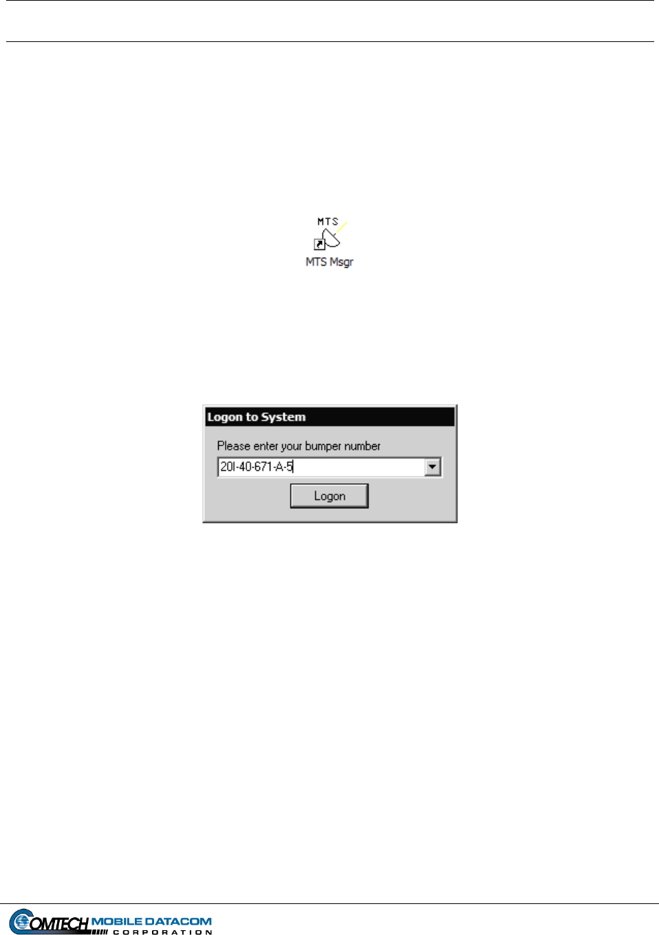
Contract No. DAAB15-99-D-0014 MTS Users Manual Revision: 1.9.1a
Page 5-1
5. MTS Messenger (V2, CONTROL STATION)
5.1 Starting MTS Messenger
NOTE: Your computer will be configured to open MTS Messenger automatically.
If this function is not enabled, follow the steps listed below.
(1) To start MTS Messenger, double-click the MTS Messenger Icon located on the
desktop.
Figure 5-1 The MTS Messenger Icon
(2) Users will be prompted to enter their bumper number as in Figure 5-2.
(a) Users can enter up to 32 characters including letters, number, spaces and
dashes (-). Only the final 9 characters will be displayed on the map.
Figure 5-2 Logon Dialog
(b) The previous three entered bumper numbers are saved in the drop down box.
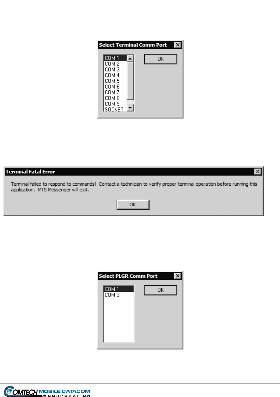
Contract No. DAAB15-99-D-0014 MTS Users Manual Revision: 1.9.1a
Page 5-2
(3) Users may be prompted to select the COM Port as in Figure 5-3.
(a) Control Station users will select COM 3 on startup.
(b) V2 users will select COM 3 (J4) on startup.
Figure 5-3 COM Port Select Window
If you receive the following error message indicating that the terminal failed to respond,
go to section 8, Troubleshooting (see Figure 5-4).
Figure 5-4 No Response from Terminal
(4) Users may be prompted to select the PLGR Com Port (Figure 5-5).
(a) Control Stations users will select COM 1.
(b) V2 users will select COM 1 (J3).
Figure 5-5 Select PLGR Com Port
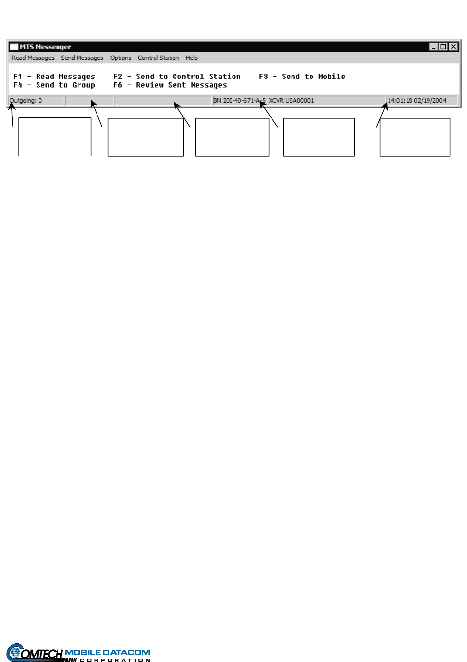
Contract No. DAAB15-99-D-0014 MTS Users Manual Revision: 1.9.1a
5.1.1 Display Screen (Command Reference)
Status Block 3
GPS Fix
Status Block 1
Outgoing
Message Queue
Status Block 2
Incoming
Message Queue
Status Block 4
N
etwork
Identification
Status Block 5
Time and Date
Quality
Figure 5-6 Main MTS Messenger Window (Command Reference)
After selecting the COM ports for the terminal and the PLGR, the standard display
screen also known as the command reference, will appear (see Figure 5-6). The main
window consists of a menu bar, a display screen, and a status bar broken into 5
blocks. If certain help menu functions are enabled, the display screen will show
diagnostics information. Only system administrators will use those functions.
5.1.2 Display Screen – Status Blocks
The MTS Messenger Status Blocks can be found on the bottom of the display screen
(command reference). The Status Blocks are numbered from left or outbox right
starting with Block 1.
(1) Status Block 1 contains the outgoing messages queue. This should always be
0, unless a message has just been sent, then it will be 1 for an instant.
(2) Status Block 2 contains the incoming messages queue. It displays the number
of unread messages.
(3) Status Block 3 contains the status of the PLGR. When the PLGR receives a
valid GPS Fix, it will be displayed in the form of a FOM (Figure of Merit)
number. A figure of merit of 5 or below will allow the MTS to report the
unit’s position. MTS positions will not be displayed with a FOM above 5.
(4) Status Block 4 contains the Bumper number (BN) and the transceiver ID
(XCVR). The BN will appear after the network registration response has been
received from the ground station.
(5) Status Block 5 contains the time in UTC. The time is retrieved from the GPS
receiver inside the PLGR.
Page 5-3
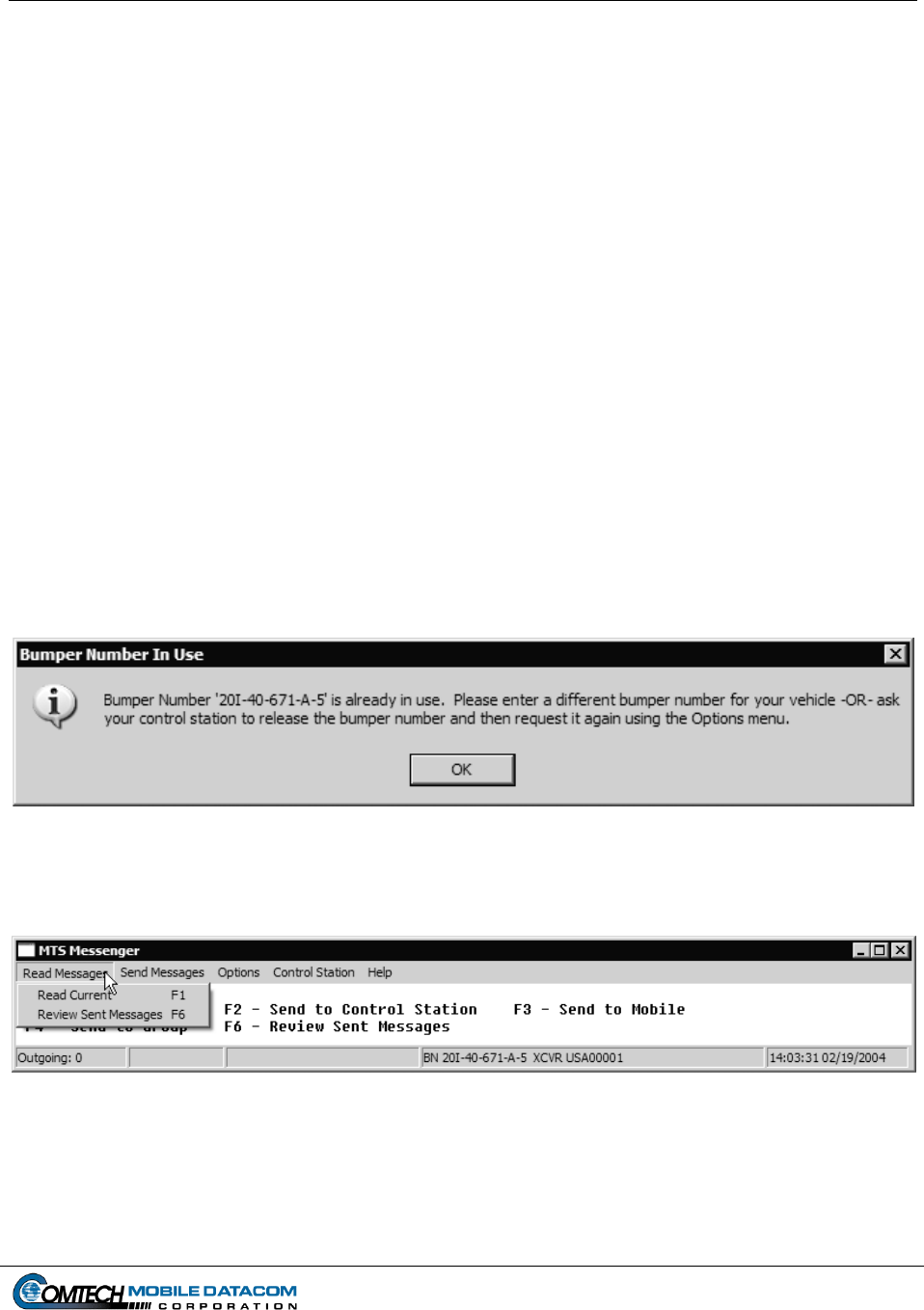
Contract No. DAAB15-99-D-0014 MTS Users Manual Revision: 1.9.1a
Page 5-4
5.2 Network Registration
Once the main window (command reference) appears, wait for network registration.
The bumper number and transceiver ID will appear in Status Block 4 at the bottom
when network registration completes (see Figure 5-6). Network registration is the
process in which a transceiver is recognized as an authorized node within the MTS
network. During network registration, MTS Messenger sends a request message to
the network every 2 minutes until a response is received. Until the initial network
response comes back, you cannot send and receive messages to and from other units.
If the transceiver is under trees, inside a building, or shadowed by a large object, it
may not be able to communicate with the satellite, and therefore never receive a
registration response. In that case, move the blockage or vehicle so the unit can
communicate.
If the bumper number that you entered is already assigned to another transceiver, you
will receive a warning message that the bumper number entered is not available (see
Figure 5-7). You will then be assigned a default bumper number consisting of USA
and a number (e.g. USA01234). To request a different bumper number take the
Change Bumper Number option on the Options menu (see Section 5.5.5). Alternately
you can request that a control station release the bumper number using the Release
Bumper Number option on the Control Station menu (see Section 7.1.6) and then use
the Change Bumper Number option on the Options menu (see Section 5.5.5).
Figure 5-7 Bumper Number in use warning
5.3 The Read Messages Menu
Figure 5-8 Read Messages Pull Down Menu
To read messages you have received and messages you have sent to other units you can
either use the Read Messages pull-down menu (see Figure 5-8) with the mouse or the
function keys on the keyboard (F1 and F6).
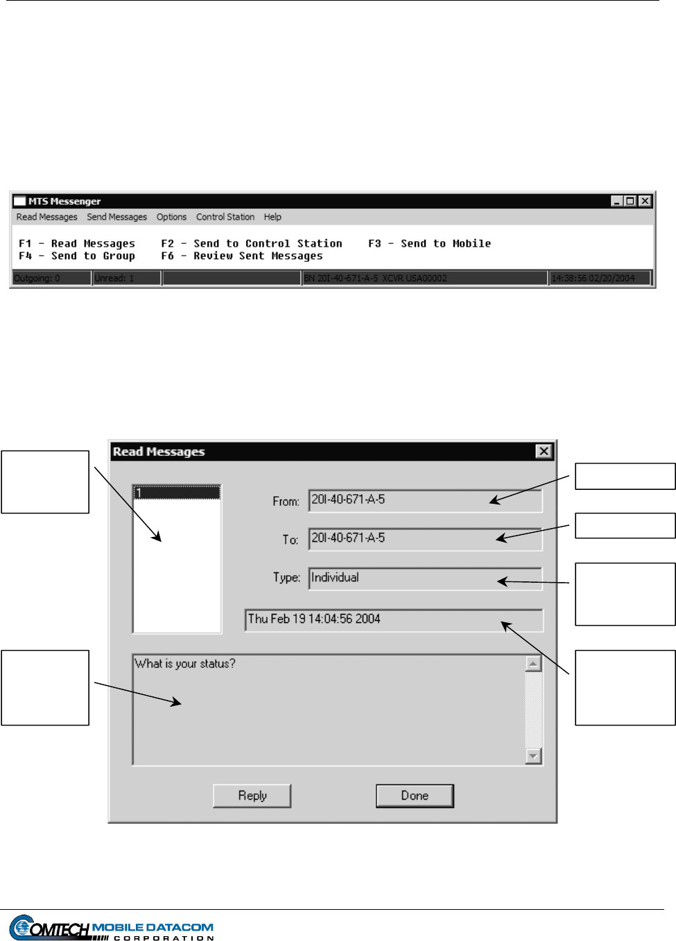
Contract No. DAAB15-99-D-0014 MTS Users Manual Revision: 1.9.1a
TIP: Using keyboard shortcuts such as the function keys (F1 and F6) and the tab key are
easier and faster to use than the mouse once you are familiar with them.
5.3.1 Reading Received Messages
If the incoming messages queue indicator in Status Block 2 shows unread messages
all of the Status Blocks will be red (see Figure 5-9).
Figure 5-9 New Message
To read a message:
(1) Select Read Messages Read Current, or press F1, to read messages. Figure
5-10 shows the window that will appear.
Message
Received
List
Sender
Receive
r
Group or
Individual
Message
Message
Text Field
GMT
Date/Time
Message
Received
Figure 5-10 Read Current Messages
Page 5-5
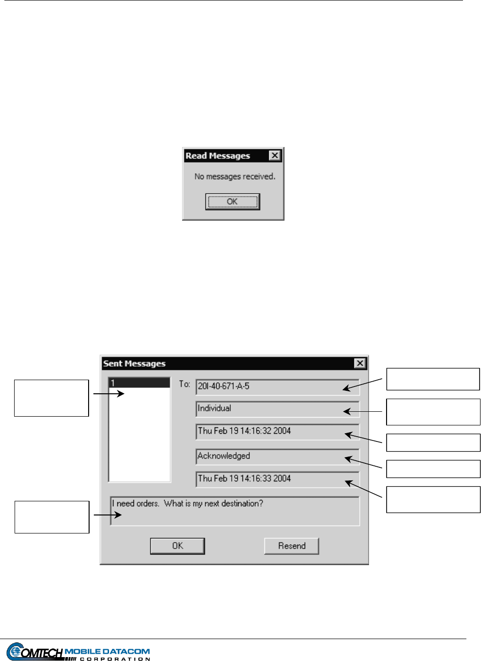
Contract No. DAAB15-99-D-0014 MTS Users Manual Revision: 1.9.1a
(2) In the Message Received List, click the message number you wish to read. It
will default to the most recent message received. The text of the message will
appear in the Message Text Field. Click the Reply button to return a message to
the sender, or the Done button to go back to the main window. Use the up and
down arrow keys to move between messages.
If you have not received any messages (for example right after you started MTS
Messenger) and you selected Read Messages Read Current via the pull down
menu or by pressing F1, you will receive an error message as seen Figure 5-11.
Figure 5-11 Read Messages Error Window
5.3.2 Reviewing a Sent Message
To review the messages that you have sent:
(1) Select Read Messages Review Sent Messages or press F6. Figure 5-12 shows
the window that will appear. The Message Sent List contains all messages sent.
Receiver Field
Message Sent
List
Individual or Group
Fiel
d
Date/Time Sent Fiel
d
Messa
g
e Status Fiel
d
Message Status Time
Fiel
d
Message Text
Field
Figure 5-12 Review Sent Messages
Page 5-6
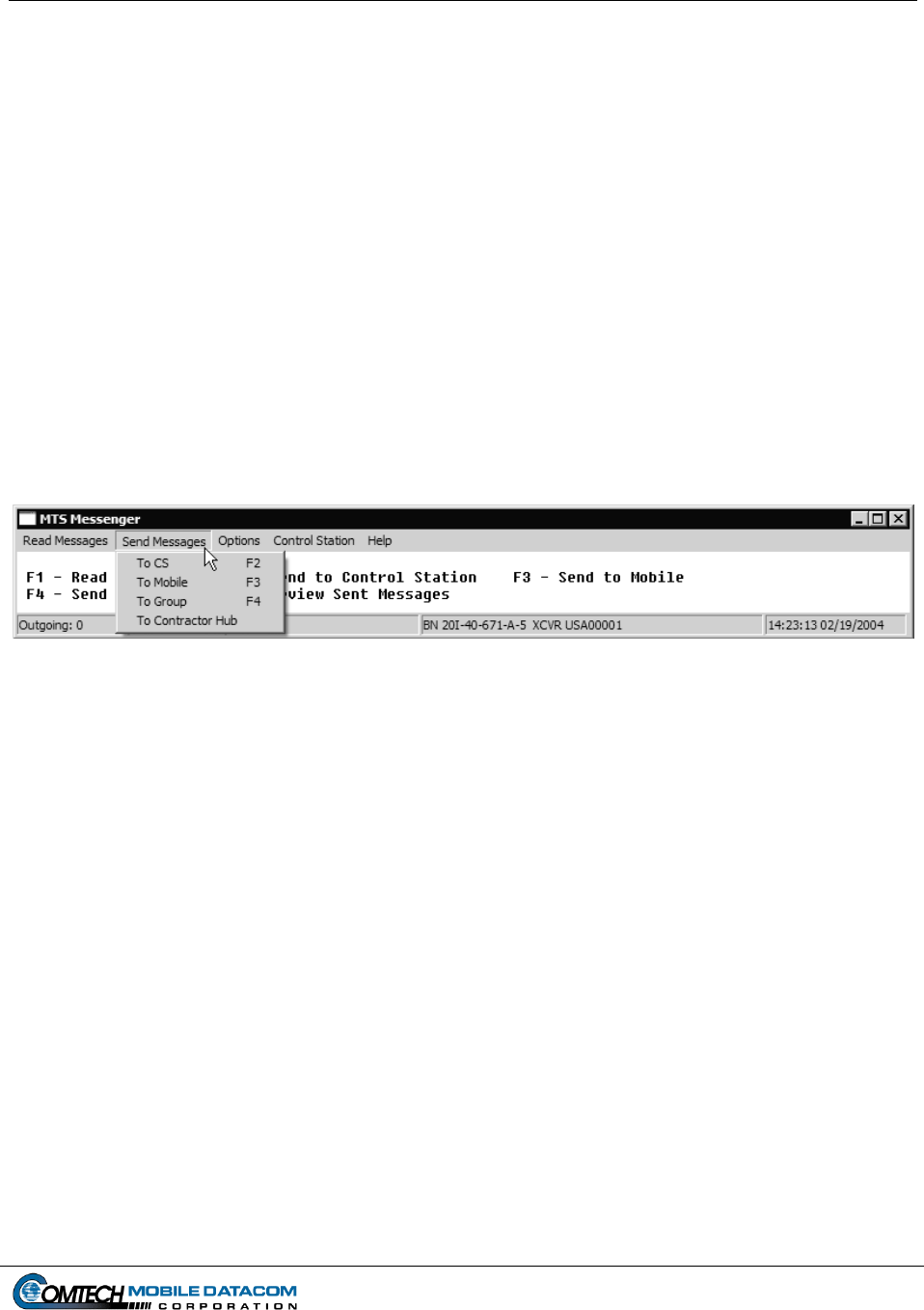
Contract No. DAAB15-99-D-0014 MTS Users Manual Revision: 1.9.1a
Page 5-7
(2) Select a message number by using the up and down arrows to move between
messages in the Message Sent List. The text and status of the sent message will
populate the other fields in the window. The Message Status Field indicates
whether the message was received at its destination. A status of Sent means it was
recently sent and there has been no response yet. A status of “Acknowledged”
means the message was received. A status of “Negative Acknowledged” means
it was not received because the destination was offline or not in view of the
satellite. A status of “Timed Out” means the sending unit (you) was blocked and
cannot communicate with the satellite. In the case of a message to the entire
Control Group (see section 5.4.2), the “Acknowledged” status will contain a list
of the units that actually received the message.
(3) Note: Once MTS Messenger is shut down all messages sent and received are
deleted; they are not saved on the system.
5.4 The Send Messages Menu
Figure 5-13 Send Messages Pull Down Menu
5.4.1 Sending a message to an Individual Unit (CS or Mobile)
To send messages to other units:
(1) Select the Send Messages pull-down menu (see Figure 5-13); or use one of the
function keys on the keyboard (F2, F3 and F4).
TIP: Using keyboard shortcuts such as the function keys (F2, F3, and F4) and the tab
key are easier and faster to use than the mouse once you are familiar with them.
(2) To send a message to a Control Station; select Send Messages To CS or press
F2. To send a message to a Mobile Unit select Send Messages To Mobile or
press F3. Figure 5-14 shows the window that will appear.
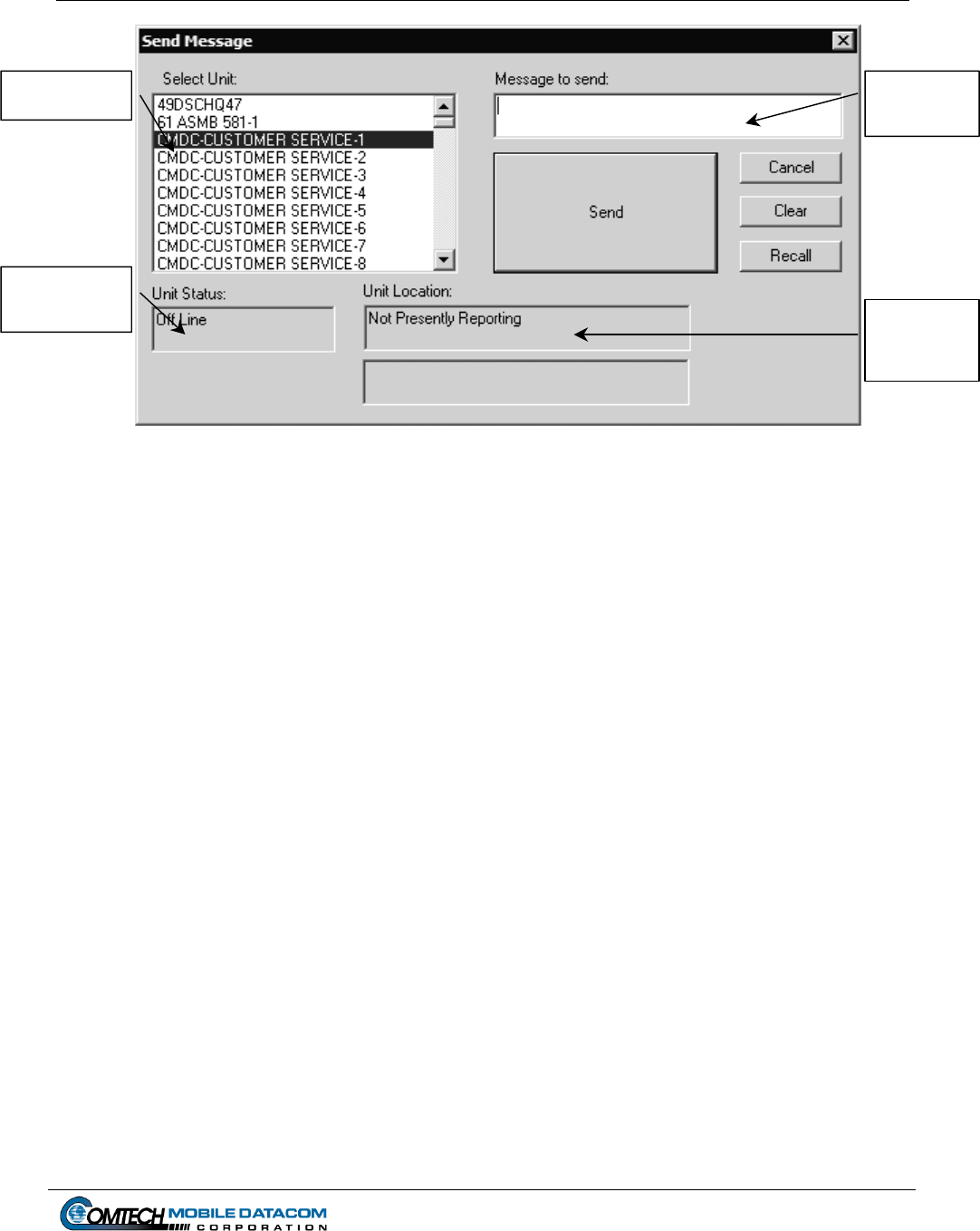
Contract No. DAAB15-99-D-0014 MTS Users Manual Revision: 1.9.1a
Message
Text Field
Select Unit List
Unit Status
Field Unit
Location
Field
Figure 5-14 Send Message to a Control Station
(3) To choose a recipient for your message, choose a unit from Select Unit List.
Before you type a message, check the Unit Status Field. This field will let you
know if the intended recipient is on line or off line. The Unit Location Field will
indicate the position of unit.
(4) Type your message into Message Text Field.
(5) Once satisfied that your message is complete press the Send button. Press the
Cancel button to return to the main window without sending the message. Push
the Recall button to load the last sent message into the Message Box. Press the
Clear button to clear the message text field.
(6) Go to Read Messages Review Sent Messages to see if the recipient received
the message. See Reviewing a Sent Message in section 5.3.2.
Page 5-8
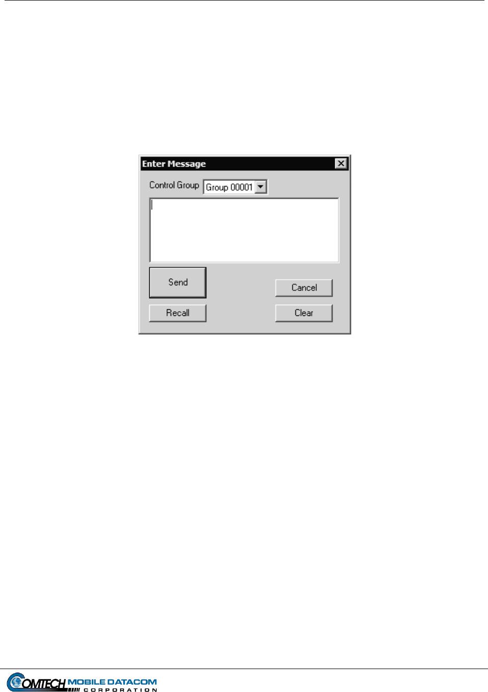
Contract No. DAAB15-99-D-0014 MTS Users Manual Revision: 1.9.1a
Page 5-9
5.4.2 Send a Message to All Members of the Control Group
To send a message to your entire group:
(1) Select Send Messages To Group, or press F4, to send a message to all
members of the Control Group except the sender. Figure 5-15 shows the window
that will appear. Mobile units will only see one Control Group, while Control
Stations might be members of several Control Groups. Control Stations will have
to use the pull down menu to select the appropriate group.
Figure 5-15 Send Message to Control Group Window
(2) Enter the text in the Message Text Field and press the Send button. Pressing the
Recall button will load the message box with the text from the last message sent.
To close the window without sending a message, press the Cancel button. To
erase any text in the Message Text Field press the Clear button.
(3) After sending a message, go to Read Messages Review Sent Messages to see
if any group members received the message. See Reviewing a Sent Message in
section 5.3.2.
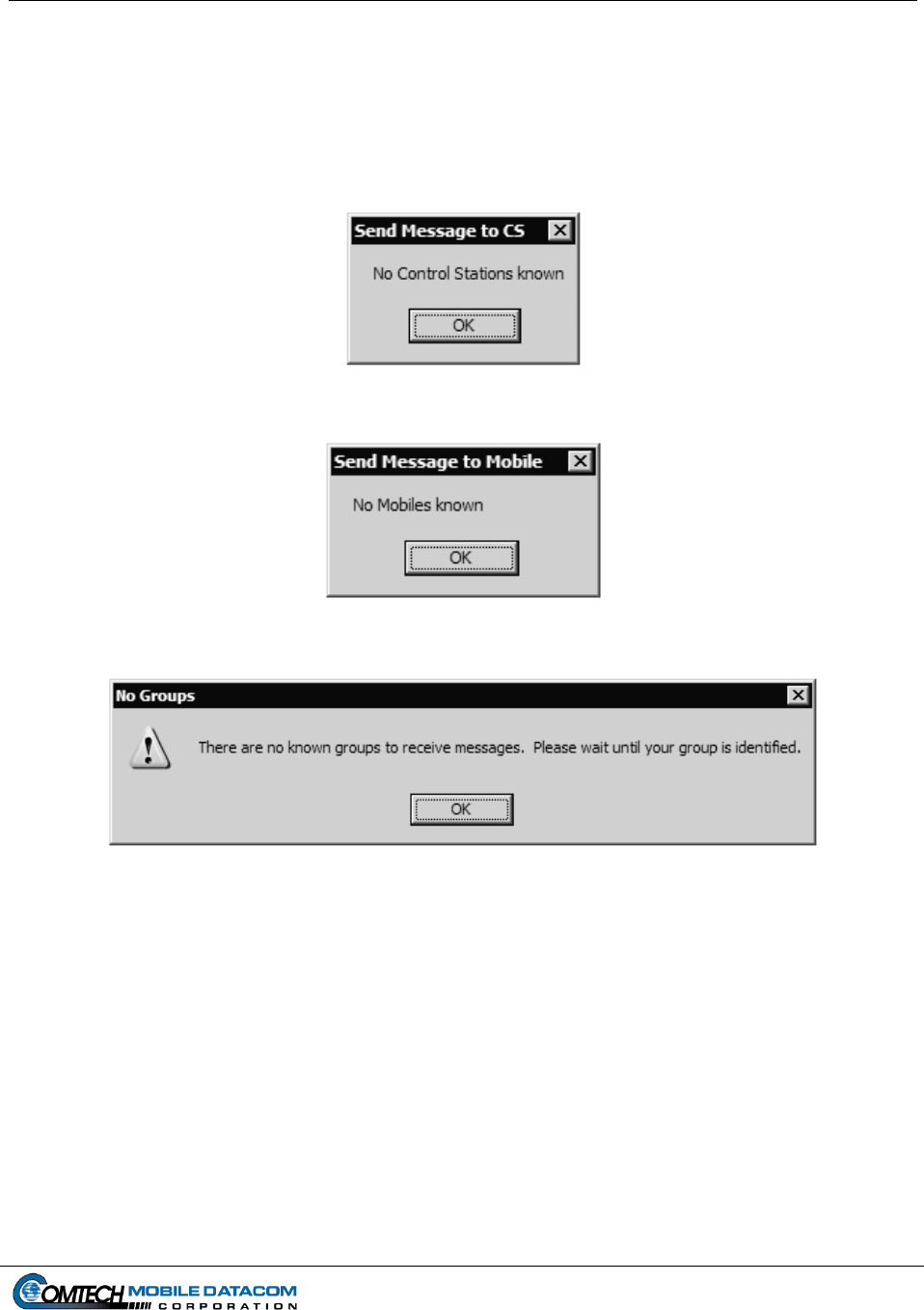
Contract No. DAAB15-99-D-0014 MTS Users Manual Revision: 1.9.1a
Page 5-10
5.4.3 Sending Messages Outside of Group
A unit can exist outside any Control Group. If a unit has not been assigned a Control
Group the user will not be able to send a message to any other unit. If the user does
attempt to send a message, the user will see one of the following messages (Figures 5-
16, 5-17, 5-18):
Figure 5-16 No Control Station Known Message Window
Figure 5-17 No Mobile Known Message Window
Figure 5-18 No Groups Known Message Window
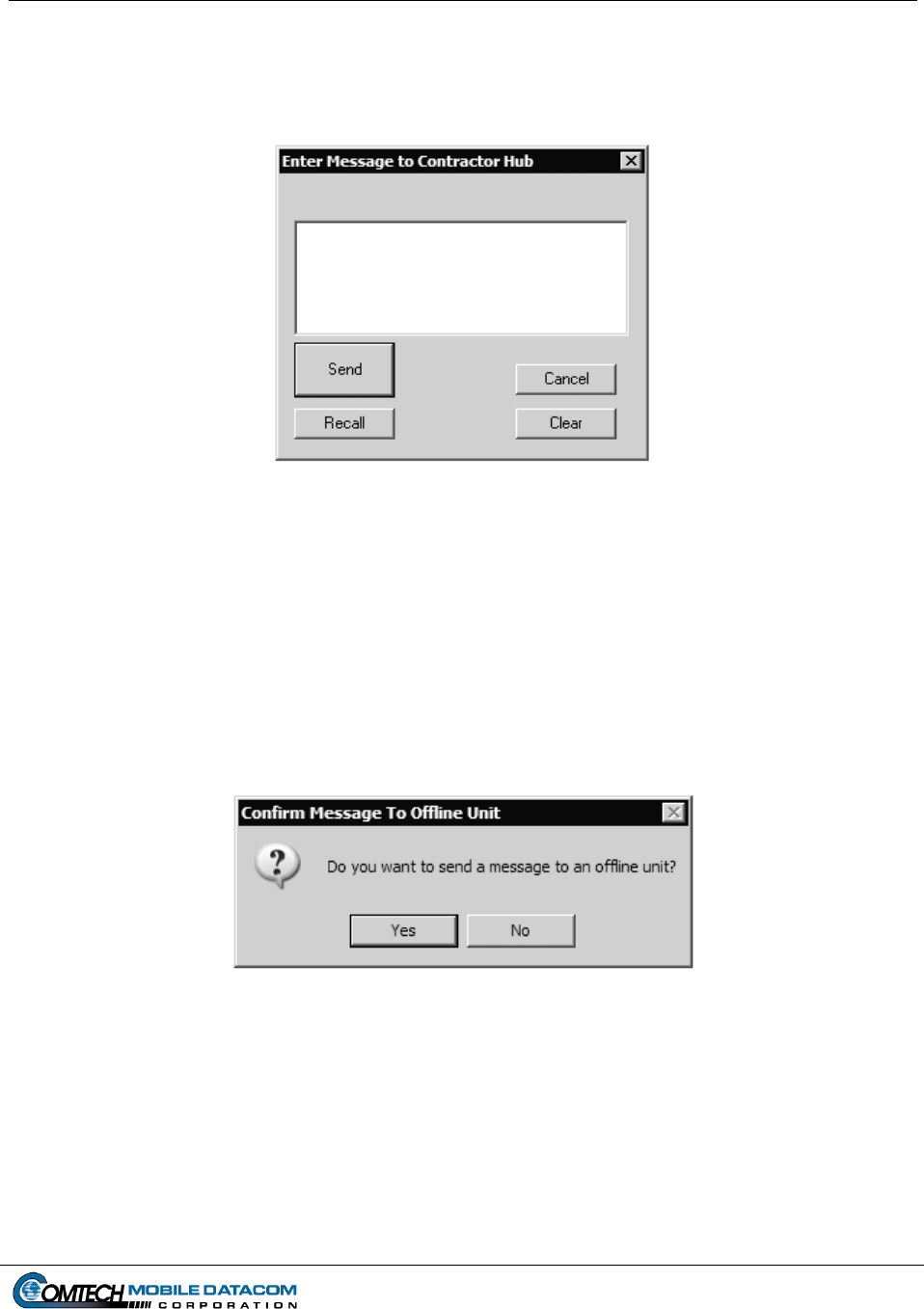
Contract No. DAAB15-99-D-0014 MTS Users Manual Revision: 1.9.1a
Page 5-11
5.4.4 Sending messages to the Contractor Hub
To send a message to the Contractor Hub, Select Send Messages from the MTS
Messenger menu, then select To Contractor Hub (see Figure 5.19).
Figure 5-19 Enter Message to Contractor Hub
5.4.5 Sending a Message to an Offline Unit
When sending a MTS message to a unit that is Offline, a dialog box will appear
asking for confirmation before sending the message (See Figure 5-20). Units that are
offline cannot receive messages and will not receive messages that were sent to them
while they were offline. Units that have just signed on to the system will appear as
offline until they send a position report to the server, however they can still receive
messages. In general, sending messages to an offline unit is not recommended.
Figure 5-20 Confirm Message to Offline Unit dialog box
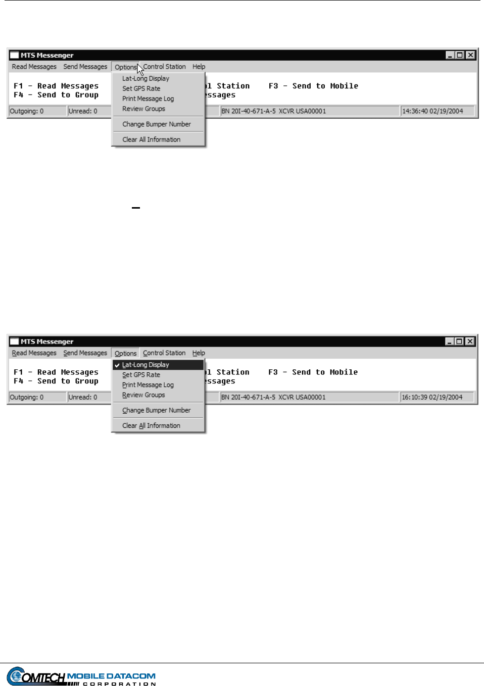
Contract No. DAAB15-99-D-0014 MTS Users Manual Revision: 1.9.1a
Page 5-12
5.5 The Options Menu
Figure 5-21 Options Pull Down Menu
5.5.1 Options Lat-Long Display
The Lat-Long Display function changes the format of the position data displayed in
the Unit Location Field of the Send Message windows. When Lat-Long is not
selected, the Unit Location Field shows the data in MILGRID format (Figure 5-24).
The default format is in MILGRID format. When Lat-Long is selected, the location
of the unit is displayed in standard civilian Latitude and Longitude coordinates
(Figure 5-23) and the option will have a check mark next to it on the menu (Figure 5-
22).
Figure 5-22 Checked Lat-Long Display Menu Option
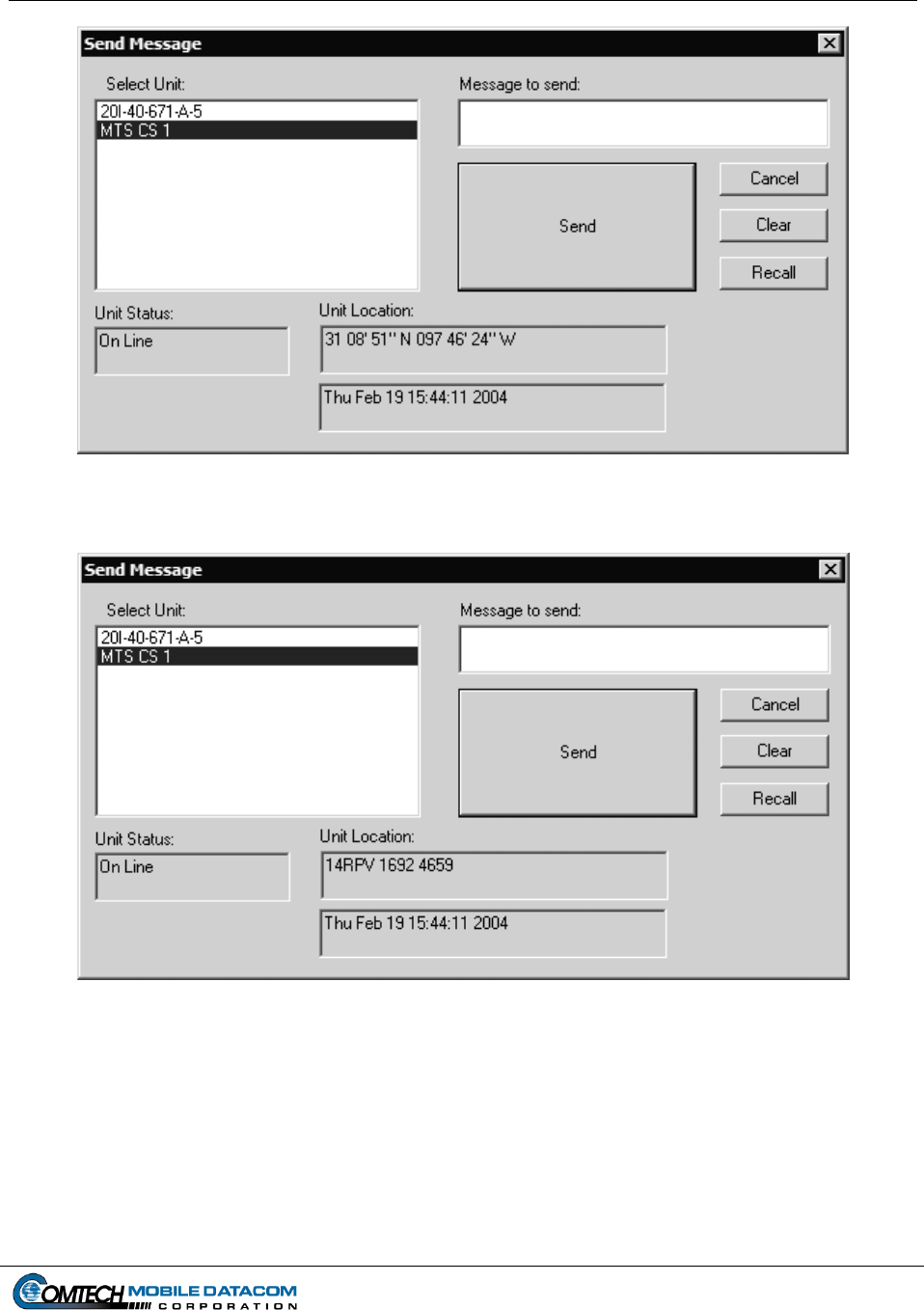
Contract No. DAAB15-99-D-0014 MTS Users Manual Revision: 1.9.1a
Page 5-13
Figure 5-23 Lat-Long Display
Figure 5-24 MILGRID Display
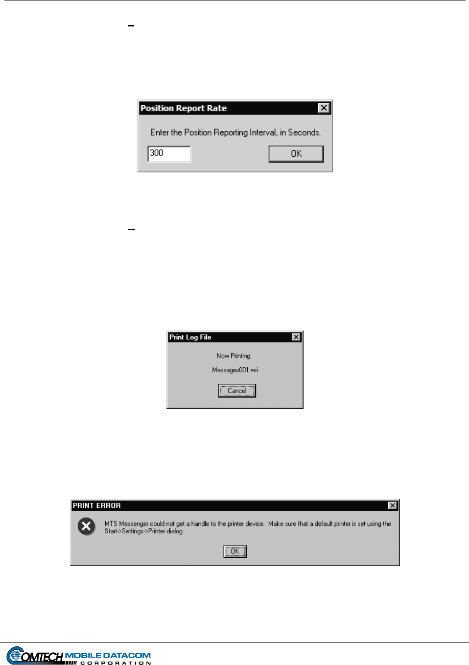
Contract No. DAAB15-99-D-0014 MTS Users Manual Revision: 1.9.1a
Page 5-14
5.5.2 Options Set GPS Rate
Set GPS Rate allows the user to increase the GPS reporting that the terminal sends
back to the Control Station (see Figure 5-25). The default rate for MTS is five
minutes (300 seconds). The minimum rate is also five minutes.
Figure 5-25 Position Report Rate
5.5.3 Options Print Message Log
The Print Message Log is only available to Control Station computers that are
connected to a printer. The Print Message Log option creates a message log file,
spools it to the default printer and then disappears. Pressing the Cancel button will
stop the printing of the file. A Print Log File Message window (Figure 5-26) will
pop-up to confirm that the file is printing.
Figure 5-26 Print Messages Window
If there is no printer attached to the computer, the following two messages will be
displayed (Figures 5-27 and 5-28):
Figure 5-27 Print Error
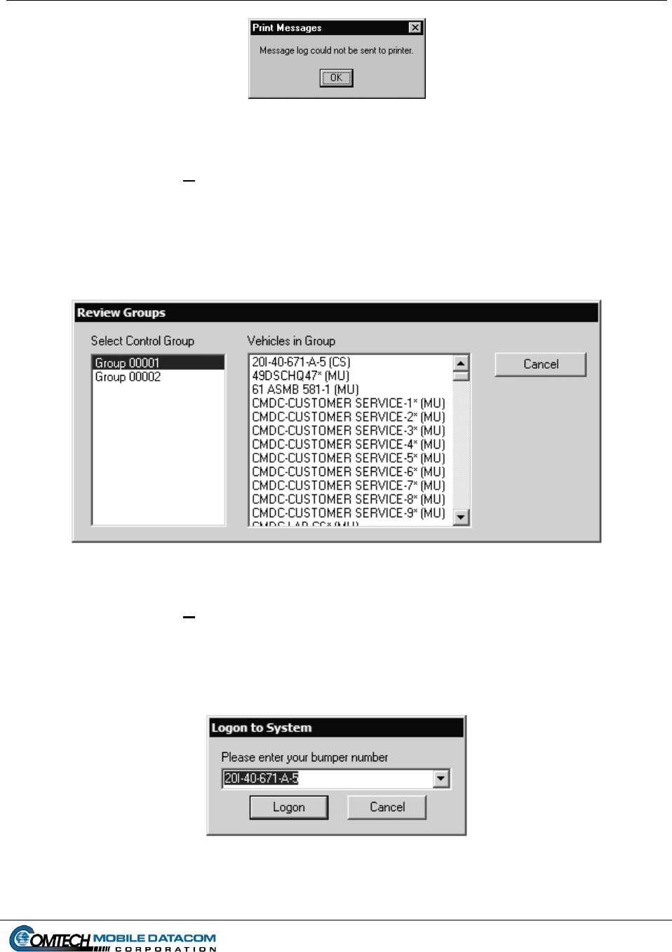
Contract No. DAAB15-99-D-0014 MTS Users Manual Revision: 1.9.1a
Page 5-15
Figure 5-28 Print Error Message Window
5.5.4 Options Review Groups
To Review the vehicles assigned to various groups, select Review Groups from the
Options Menu of MTS Messenger. The Review Control Groups window will
appear (Figure 5-29). Select a group from the Select Control Group. The vehicles
assigned within the selected group will be displayed in the Vehicles in Group box.
Figure 5-29 Review Control Groups
5.5.5 Options Change Bumper Number
To change your bumper number, select Change Bumper Number from the Options
Menu of MTS Messenger. The logon dialog will be displayed as if MTS Messenger
was just started (see Figure 5-30 and Section 5.1 (2)).
Figure 5-30 Change Bumper Number
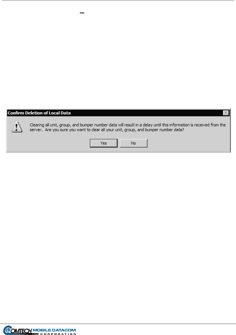
Contract No. DAAB15-99-D-0014 MTS Users Manual Revision: 1.9.1a
Page 5-16
5.5.6 Options Clear All Information
DO NOT USE THIS OPTION UNLESS DIRECTED TO BY COMTECH
CUSTOMER SERVICE.
To delete all locally stored group and bumper number information, select the Clear
All Information option from the Options Menu on MTS Messenger. Selecting this
option will cause a warning to appear (see Figure 5-31). If Yes is selected at the
warning message, all locally stored information (except messages) will be
immediately deleted. This information will then be downloaded again from the
server, while the information is being downloaded you will not be able to see any
groups, units, or bumper numbers and may make MTS Messenger unusable for 45
minutes or more.
Figure 5-31 Clear All Information Warning
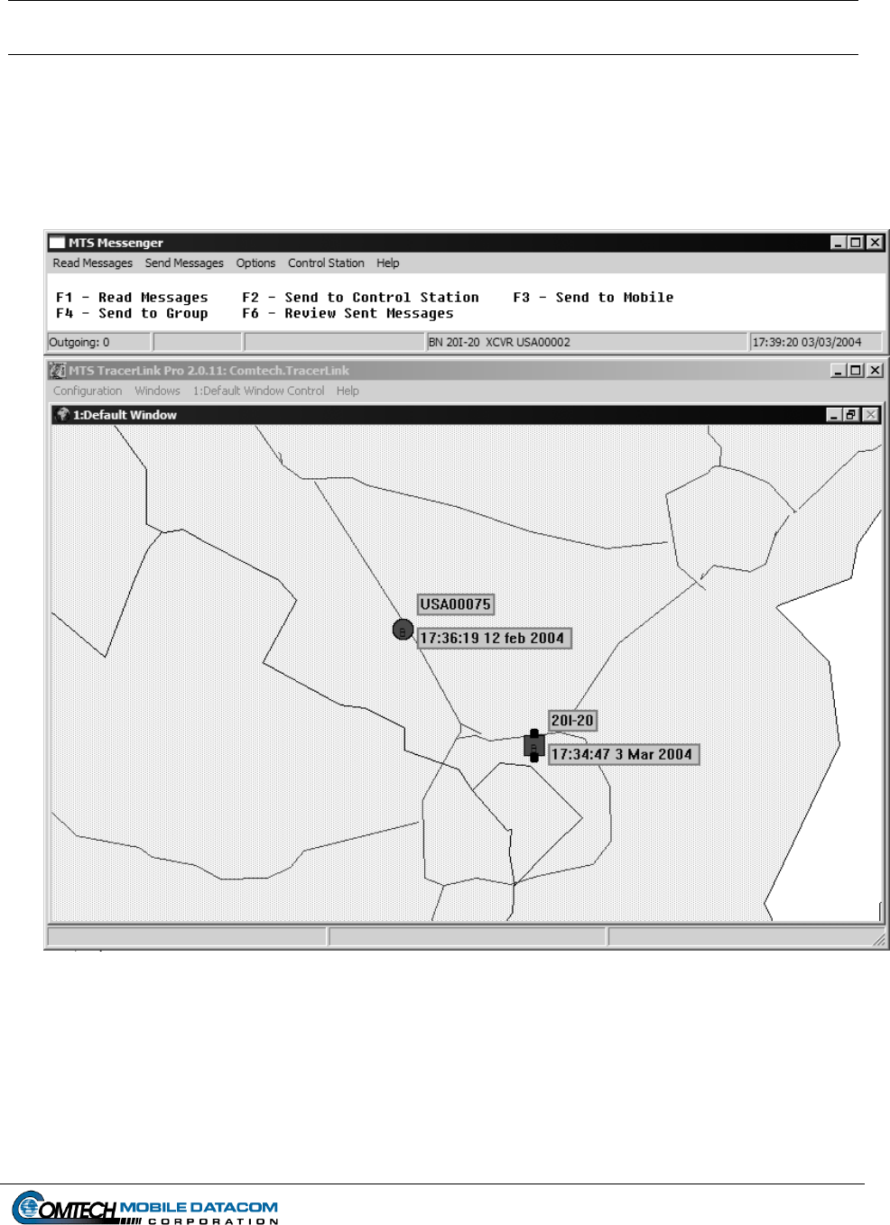
Contract No. DAAB15-99-D-0014 MTS Users Manual Revision: 1.9.1a
Page 6-1
6. TracerLink Mapping, Version 2.0.11 (Control Station and V2)
TracerLink is the Commercial-Off-The-Shelf (COTS) mapping software package that comes
standard with every Control Station and V2 configuration. TracerLink and MTS Messenger
work simultaneously so that users can send messages and view their position (and the
position of others in their group) at the same time. Figure 6-1 shows TracerLink and MTS
Messenger on a user’s screen.
Figure 6-1 MTS Messenger and Tracerlink Startup
Contained within this section is a condensed version of the TracerLink Pro user and
configuration manual explaining key functions and actions. This description assumes all map
configuring has been done. The TracerLink Pro Manual is available upon request from
Comtech Mobile Datacom, but is not included in the transit case.
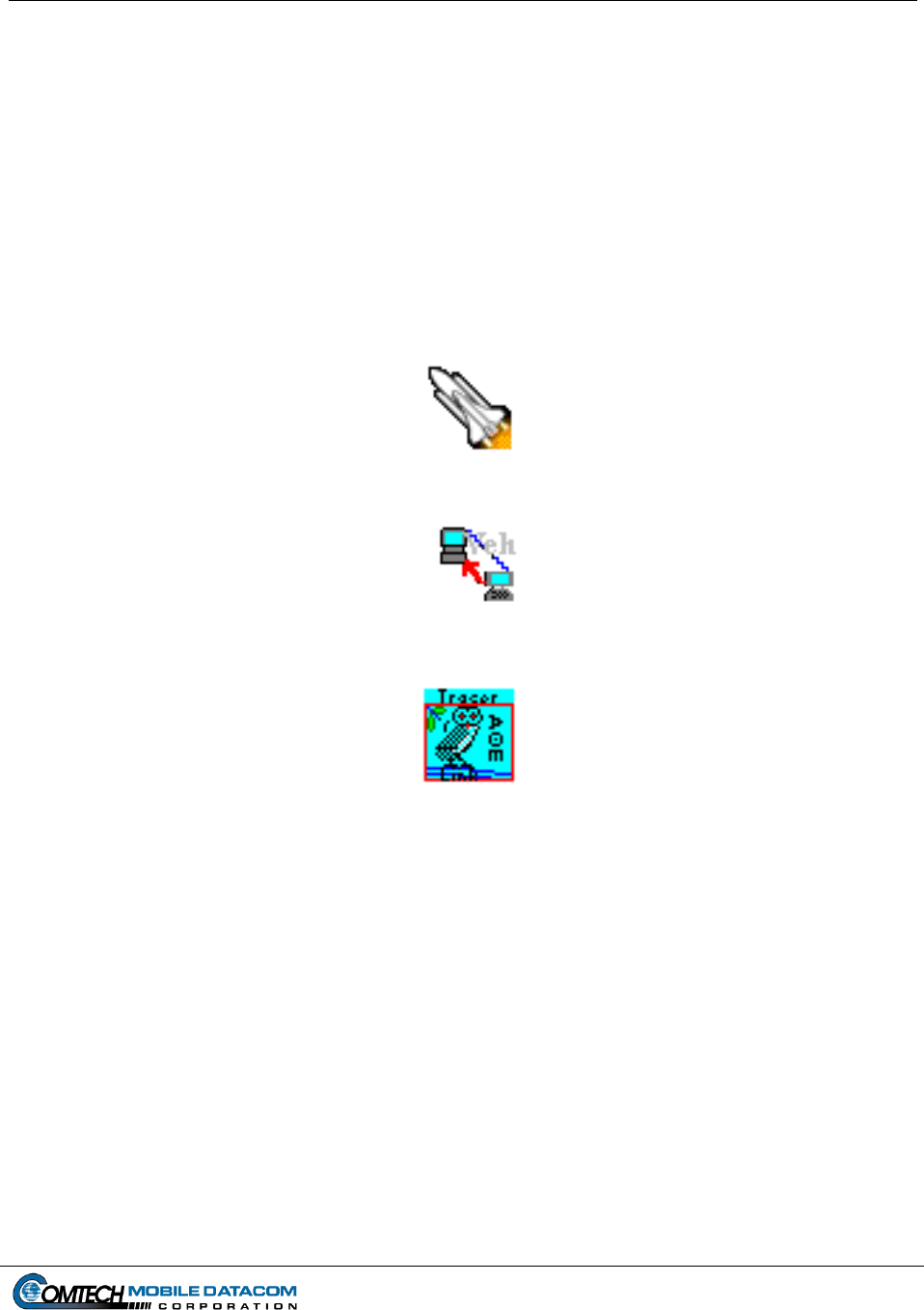
Contract No. DAAB15-99-D-0014 MTS Users Manual Revision: 1.9.1a
Page 6-2
6.1 Starting TracerLink
Double-click the Tracerlink Launcher icon (see Figure 6-2) located on the desktop to
start the TracerLink application. Tracerlink connects to the MTS Messenger program
over a TCP/IP socket to receive position data. In order for TracerLink to function,
MTS Messenger must be running.
An alternative but slightly more complicated method to start TracerLink requires the user
to double click the TracerLink Vehicle Server icon (see Figure 6-3) and the
TracerLink Map Viewer (see Figure 6-4) icon. The user should first startup the
Vehicle Server. After the Tracerlink Vehicle Server window opens, the user should
minimize it. Next double-click on the Tracerlink Map Viewer icon.
Figure 6-2 Tracerlink Launcher Icon
Figure 6-3 Tracerlink Vehicle Server Icon
Figure 6-4 Tracerlink Map Viewer Icon
6.2 The Windows
When Tracerlink starts, it runs two processes, each with its respective window. They are
the Vehicle Server, and the Map Viewer. Figure 6-5 shows the Vehicle Server window.
If started automatically by the Tracerlink Launcher icon, the window starts in the
minimized view. If a user decides to start Vehicle Server directly, rather than using the
TracerLink Launcher Icon, the Vehicle Server window will not automatically open
minimized. When open, the window will appear as in Figure 6-5. The status bar in the
lower left of the window will say “COMM ACTIVE” when the Vehicle Server has
successfully connected to MTS Messenger. If this is not visible the map will not receive
any position reports and will not display any vehicles. The center status bar at the bottom
displays the last position report received from MTS Messenger.
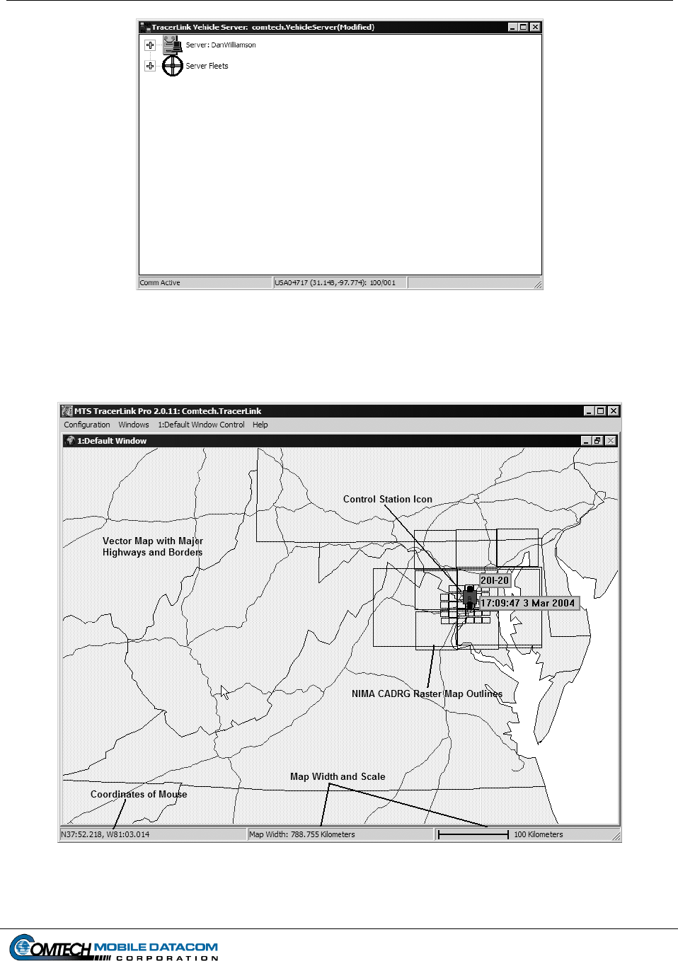
Contract No. DAAB15-99-D-0014 MTS Users Manual Revision: 1.9.1a
Page 6-3
Figure 6-5 Tracerlink Vehicle Server Window
The second Tracerlink process is the Map Viewer (see Figure 6-6).
Figure 6-6 Tracerlink Map Viewer
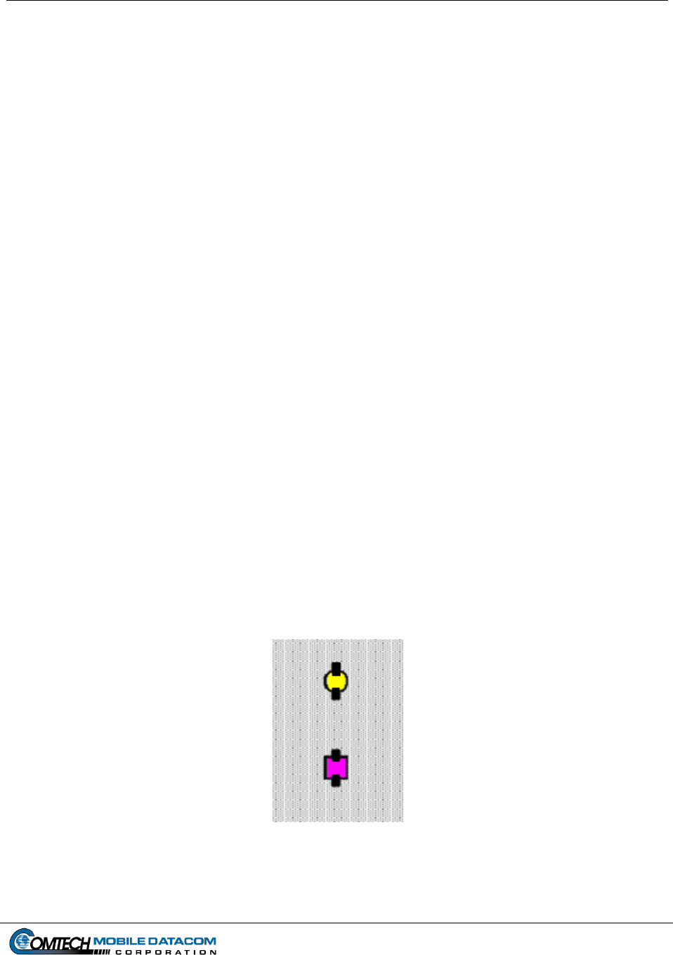
Contract No. DAAB15-99-D-0014 MTS Users Manual Revision: 1.9.1a
Page 6-4
6.3 The Maps
The Tracerlink software can display several popular map formats. MTS supports local
area NIMA CADRG (Compressed Arc Digitized Raster Graphics) maps and world
coverage vector maps. The world vector maps give the user large-scale perspective, and
the CADRG raster maps give high detail when the user zooms in. When zoomed out to a
large scale, the CADRG maps are not visible, only black rectangular outlines are visible.
As the user zooms in, the CADRG maps will load and be visible.
Tracerlink also supports reading NIMA CADRG raster maps directly off a NIMA CD-
ROM.
6.4 Symbols
Tracerlink displays various symbol shapes and colors to convey information to the user;
square symbols represent Control Stations, while round symbols represent Mobile Units.
A square lug on top of the symbol indicates the unit is turned on and transmitting. No lug
on top indicates the unit is turned off, and the position on the map is the last known
position of that vehicle. When turned on, MTS units send a position report every five
minutes to the satellite ground station. The MTS system will display an icon as off if the
ground station has not received a position report in over ten minutes from a particular
vehicle.
The color of the symbol indicates the Control Group the vehicle belongs to. All vehicles
in the same Control Group will be the same color.
A square lug on the bottom of a symbol indicates the vehicle is reporting valid GPS. If a
unit is powered on, but is not reporting valid GPS, then the location of the icon on the
screen reflects the last known position of the vehicle, and may not reflect the current
position of the vehicle. See Figure 6-7 for an example of the symbols.
Figure 6-7 Symbols Representing Mobile Units and Control Stations
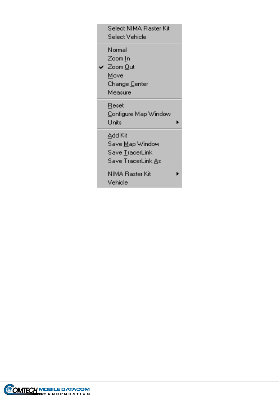
Contract No. DAAB15-99-D-0014 MTS Users Manual Revision: 1.9.1a
Page 6-5
6.5 Right Click Pop Up Menu
Figure 6-8 Right Click Pop Up Menu
The fastest and easiest way to use many of the functions in TracerLink is to activate the
Right Click Pop Up Menu (see Figure 6-8). To activate this menu, simply right click
your mouse on the Map Viewer.
6.5.1 Select NIMA Raster Kit
Go to Section 6.7 NIMA CADGR Maps for more details on this function.
6.5.2 Select Vehicle
Go to Section 6.6 Server Vehicle Kit Control Window for more details on this
function.

Contract No. DAAB15-99-D-0014 MTS Users Manual Revision: 1.9.1a
Page 6-6
6.5.3 Zooming the Map
Zooming in provides more detail for a specific area, while zooming out is a way to
show less detail, but more geographic area. The zoom function, works a bit like a
camera’s zoom lens. A user can zoom in multiple times to get very close to a specific
location. Or the user can zoom out and get very far from the same location.
To zoom, right click on the map to show the pop up menu, (see Figure 6-8). Select
Zoom In or Zoom Out. Click on the map at the point you wish to become the center
of the map. The map will zoom with the point clicked becoming the new center of the
map.
Zoom In also supports window zooming. Click the left mouse button and drag it to
form a box around the area you wish to see enlarged.
TIP: While zooming in or out, the user can click the mouse several times and the
software will skip the intermediate redraws. So instead of clicking, waiting, clicking,
and waiting, just click several times and wait once.
6.5.4 Change Center
Panning is a way to move north, south, east, or west while staying at the same zoom
level. Right click the mouse over the map to pop up the menu (see Figure 6-8), select
Change Center. Click on the map and the map will move with the point clicked
becoming the new center of the map.
6.5.5 Pan a Map (Move)
An alternate method of panning the map is to use the Move function. Right click the
mouse over the map to pop up the menu (Figure 6-8), select Move. The cursor
becomes a hand. Click on the map and hold down the left mouse button, then drag the
map to the desired position. When you release the mouse, the map will redraw in the
new position.
6.5.6 Measure Distances on Map
Distances on the map can be measured as the crow flies. Right click on the map to
pop up the menu (Figure 6-8), and then select Measure. Click and drag the cursor
from point A to point B on the map. Before releasing the mouse button, look at the
scale display at the bottom of the map window (see Figure 6-9). It displays the
distance in kilometers, nautical miles, or statute miles. Once you release the mouse,
the distance measurement will disappear.
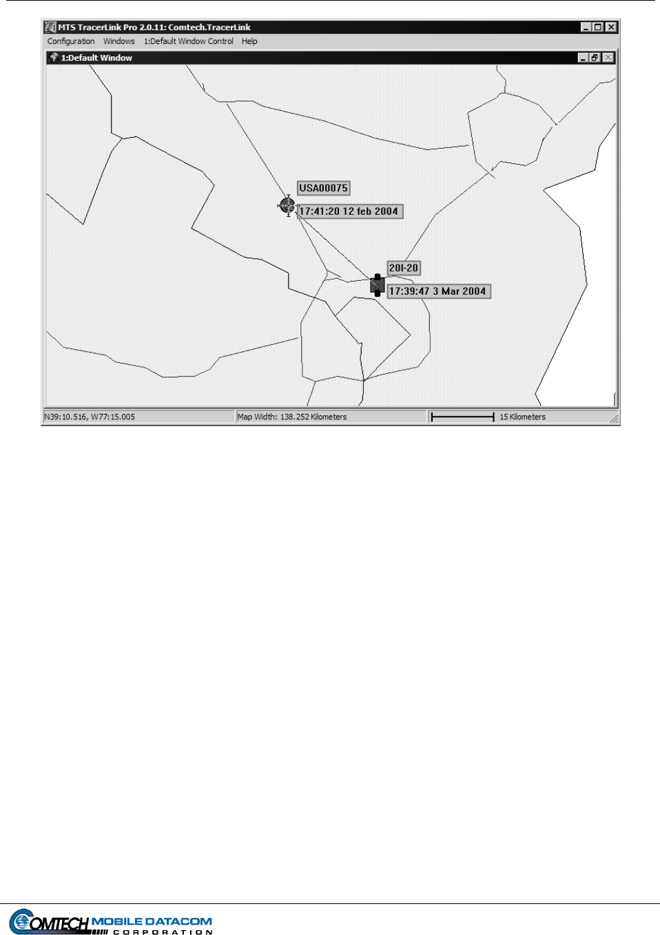
Contract No. DAAB15-99-D-0014 MTS Users Manual Revision: 1.9.1a
Page 6-7
Figure 6-9 Map Showing Measure Distances Function
6.5.7 Reset Map to Initial View
Sometimes it is possible to zoom so far out or so far in the user becomes disoriented.
Do a map Reset to return the map to the view seen at startup. Right click on the map
(Figure 6-8) and select Reset.
6.5.8 Configure Map Window
NOTE: Only experienced users should use this function. More details about this
function are available in the TracerLink Pro Installation and Operation manual.
6.5.9 Units – Changing Units of Measure
Right click on the map (Figure 6-8) and select Unit. Select whether you want the
map in Kilometers, Nautical Miles or Statue Miles.
6.5.10 Add Kit
NOTE: Only experienced users should use this function. More details about this
function are available in the TracerLink Pro Installation and Operation manual.
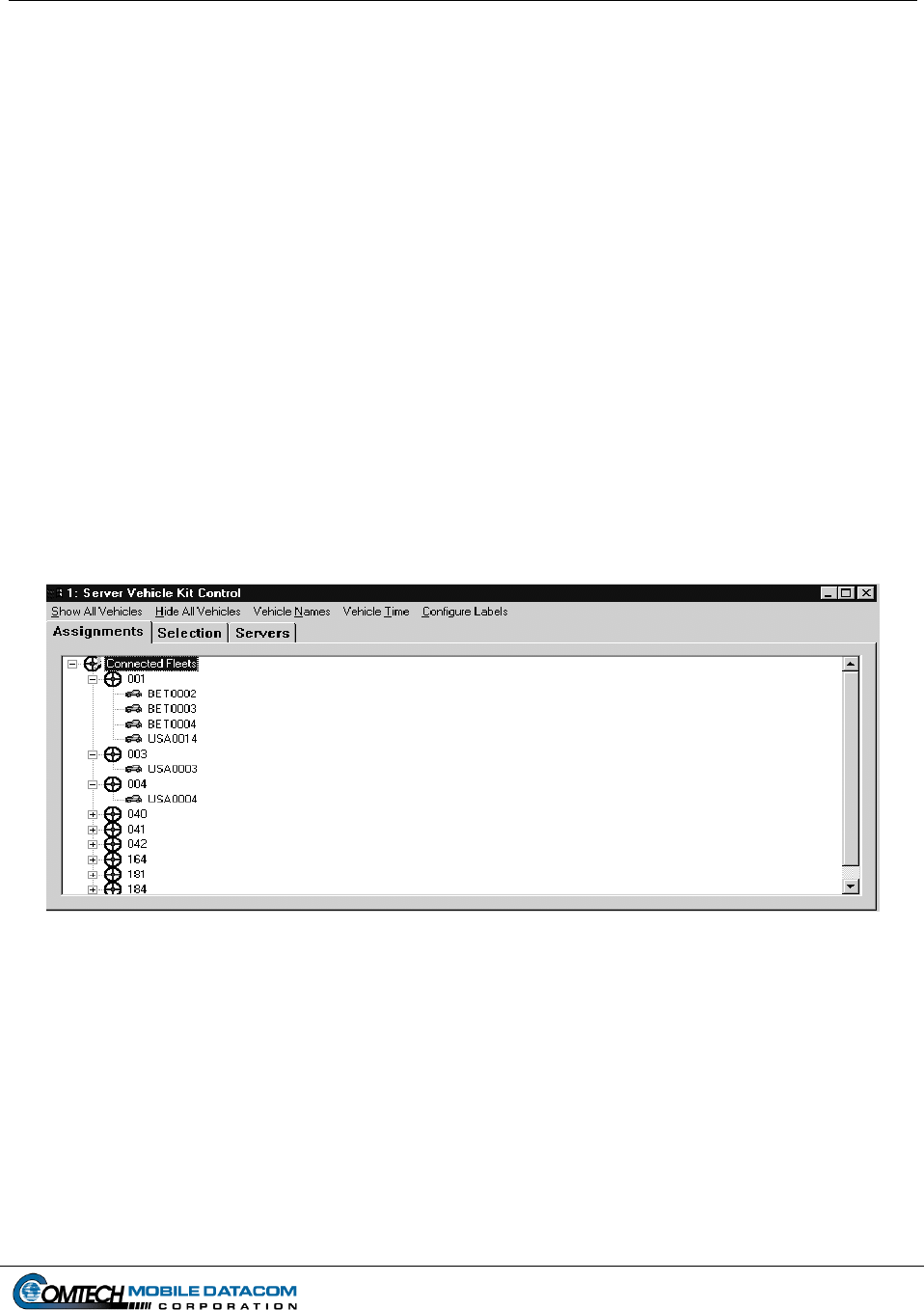
Contract No. DAAB15-99-D-0014 MTS Users Manual Revision: 1.9.1a
Page 6-8
6.5.11 Save TracerLink Window Configuration
NOTE: Only experienced users should use this function. More details about this
function are available in the TracerLink Pro Installation and Operation manual.
The user can save the map window configuration. This will save the size and location
of the window on the screen, the maps loaded, and the zoom level and center of the
map. Right click on the map (Figure 6-8), and select Save Tracerlink. If the user
doesn’t want to overwrite the previous configuration, select Save Tracerlink As.
This will allow the user to save to a different filename.
6.6 Server Vehicle Kit Control Window
The Server Vehicle Kit Control Window is a powerful tool that lets the user change
the icons (and thus the vehicles) s/he can see on the screen. Using the Server Vehicle
Kit Control tools, the user can perform some of the following functions:
Trace a vehicle’s route.
Hide a vehicle, or display a vehicle that was previously hidden.
Hide / display a vehicles name and last position report time.
Figure 6-10 Server Vehicle Kit Control Window
These functions require that the user bring up the Server Vehicle Kit Control
window (Figure 6-10), also known as the vehicle kit window. There are two ways to
bring the window up.
Right click the mouse and choose Select Vehicle on the pop up menu. This will
change your cursor into a hand with a pointed finger. Left click on the map (with the
hand) either over a vehicle’s icon or over a bare spot. If you clicked over a vehicle’s
icon, the vehicle kit window will display the clicked vehicle(s) in the pane. If you
clicked over a bare spot on the map, the vehicle kit window will be empty. Figure 6-
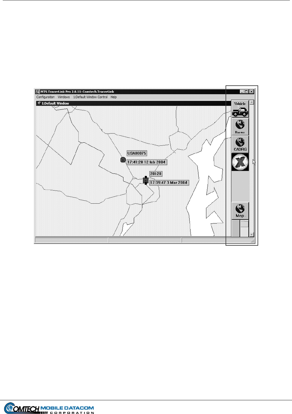
Contract No. DAAB15-99-D-0014 MTS Users Manual Revision: 1.9.1a
Page 6-9
10 shows an example where the user clicked on Comtech Mobile Datacom’s
headquarters in Germantown, Maryland. There were six icons at the location where
the user clicked.
The second method to open the Server Vehicle Kit Control window is to slowly
slide the cursor off the right side of the map. When you approach the edge of the map
the Kit Bar (Figure 6-11, highlighted) will appear. Select the Vehicle image at the
top.
Figure 6-11 Kit Bar
Once the Server Vehicle Kit Control window is up (Figure 6-10), you will see a
number of tabs within the window.
Assignments
Selection
Server
The Assignments tab and the Selection tab show the same data but in different view
formats. The Assignments tab shows all the vehicles in a hierarchical fleet view
while the Selection tab only shows the vehicles that were clicked upon by the mouse.
For example, Figure 6-12 shows one vehicle in the Selection tab because there was
one vehicle (icon) in the location that the user clicked upon. Alternatively the
Assignments tab shows several more vehicles, not just the vehicle selected.
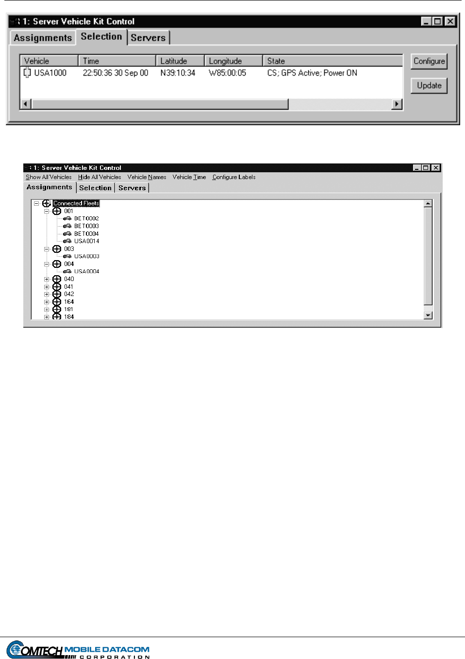
Contract No. DAAB15-99-D-0014 MTS Users Manual Revision: 1.9.1a
Page 6-10
Figure 6-12 Selection Tab (Compare with Figure 6-13)
Figure 6-13 Assignments Tab (Compare with Figure 6-12)
In many cases it is easier to select a vehicle by clicking on it on the map, and when
the Selection tab of the ‘Server Vehicle Kit Control’ window appears, operate on the
vehicle in that pane. In cases where the icon is not on the map, due to it being hidden
or off the edge of the map, it is necessary to go to the Assignments tab, open the fleet
containing the vehicle and operate on the vehicle there.
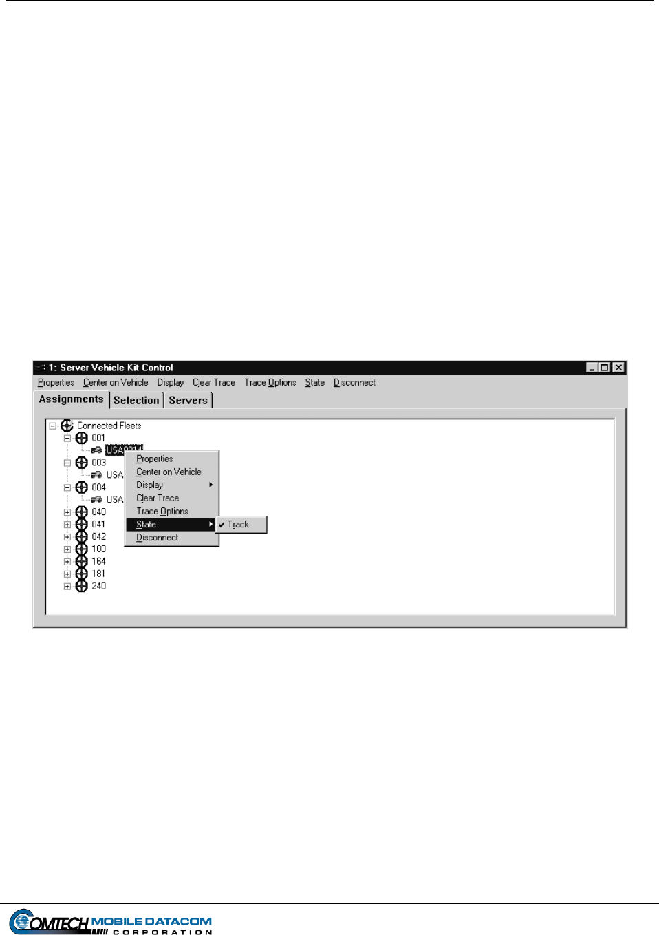
Contract No. DAAB15-99-D-0014 MTS Users Manual Revision: 1.9.1a
Page 6-11
6.6.1 Autotrack
The map can automatically pan to keep a moving vehicle within the map view.
Whenever the vehicle moves off the edge of the map, the map will automatically
shift. To enable Autotrack:
(1) Right click on the map to get the pop up menu.
(2) Choose the Select Vehicle option from the pop up menu.
(3) Click on the vehicle you wish to track. The Server Vehicle Kit Control
window will open with the Selections tab containing a list of vehicles.
(4) Right click on the vehicle you wish to track, and select State Track.
If the vehicle you wish to track is off the map, use the Assignments tab instead of the
Selections tab to make the change.
Figure 6-14 Autotrack
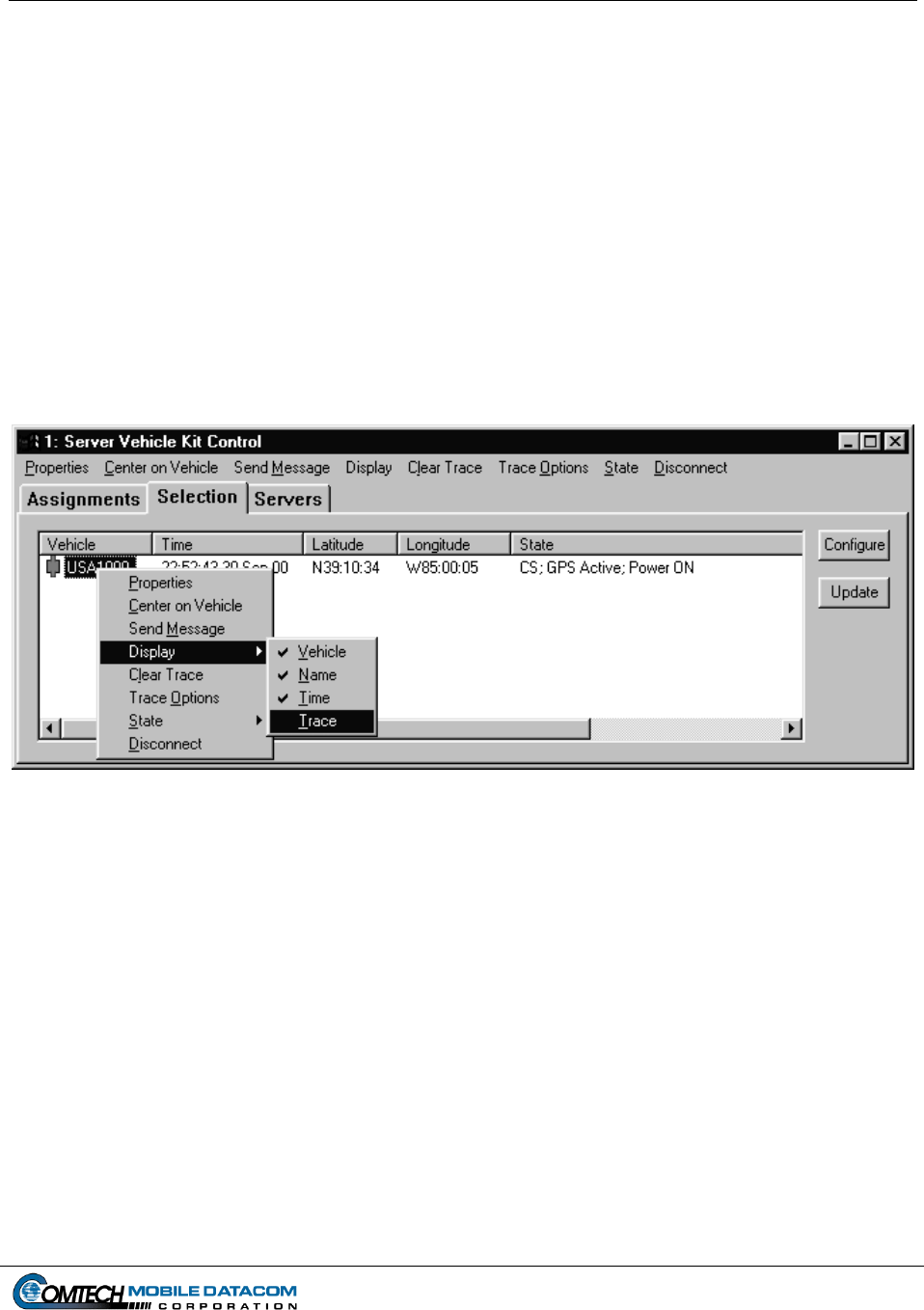
Contract No. DAAB15-99-D-0014 MTS Users Manual Revision: 1.9.1a
Page 6-12
6.6.2 Trace
The map can draw trace lines that show the history of a vehicle’s travels. To enable
the Trace function:
(1) Right click on the map to get the pop up menu (Figure 6-8).
(2) Choose the Select Vehicle option from the pop up menu.
(3) Click on the vehicle you wish to trace. The Server Vehicle Kit Control
window will open with the Selections tab containing a list of vehicles.
(4) Right click on the vehicle you wish to Trace, and then select Display
Trace (see Figure 6-15).
Figure 6-15 Tracing a Vehicle
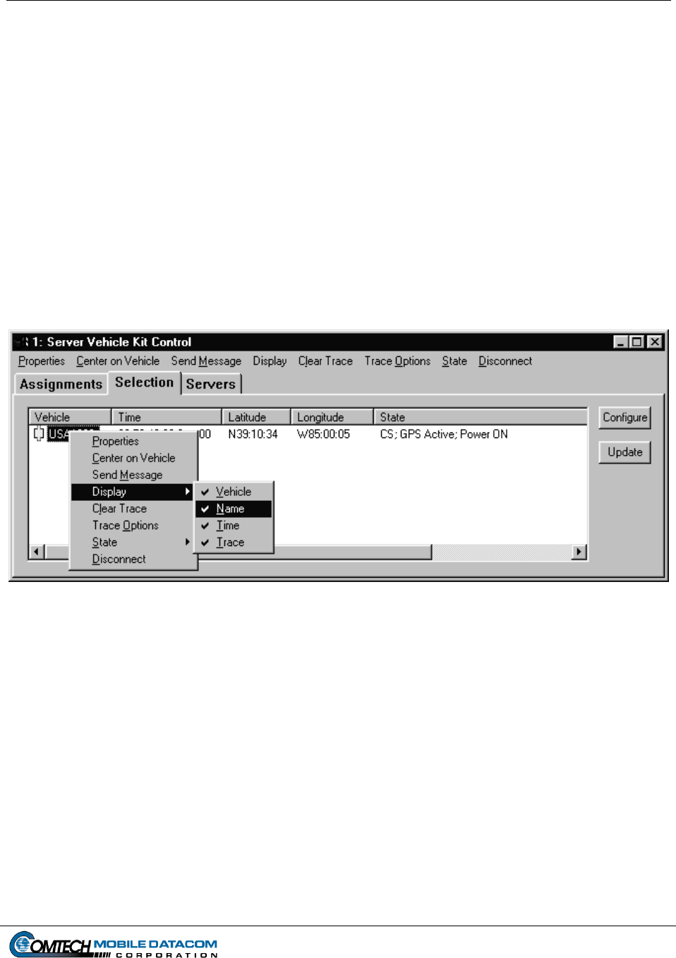
Contract No. DAAB15-99-D-0014 MTS Users Manual Revision: 1.9.1a
Page 6-13
6.6.3 Hiding and Showing an Individual Vehicle’s Name
The map can display a tag next to the symbol on the map showing a vehicle’s name.
In order to show/hide a vehicle’s name follow the steps below:
(1) Right click on the map to get the pop up menu (Figure 6-8).
(2) Choose Select Vehicle.
(3) Click on the vehicle that you wish to name (un-name). When the Server
Vehicle Kit Control window pops up it will list the vehicles.
(4) At this point you can turn the vehicle’s name on (or off). To turn the name
on, right click on the vehicle name in the Server Vehicle Kit Control
window and select Display Name (see Figure 6-16).
Figure 6-16 Display Vehicle’s Name
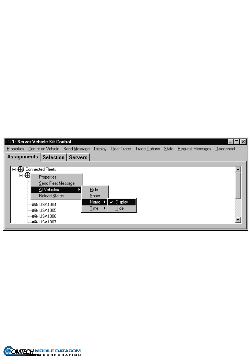
Contract No. DAAB15-99-D-0014 MTS Users Manual Revision: 1.9.1a
Page 6-14
6.6.4 Hiding and Showing Entire Control Groups
There are times when a user may want to show or hide an entire group (fleet) of
vehicles. To hide a visible group of vehicles or show a hidden group of vehicles:
(1) Right click on the map to get the pop up menu (Figure 6-8).
(2) Choose Select Vehicle.
(3) Click on the map so that the Server Vehicle Kit Control window pops up.
(4) Next, select the Assignments tab. The various Control Groups will be listed
with expandable plus boxes next to each one.
(5) Right click on a Control Group (e.g. 001,002,003, etc.), and select All
Vehicles Hide (see Figure 6-17). If a Control Group is already hidden, to
show it, simply select All Vehicles Show.
Figure 6-17 Hiding and Showing a Group of Vehicles
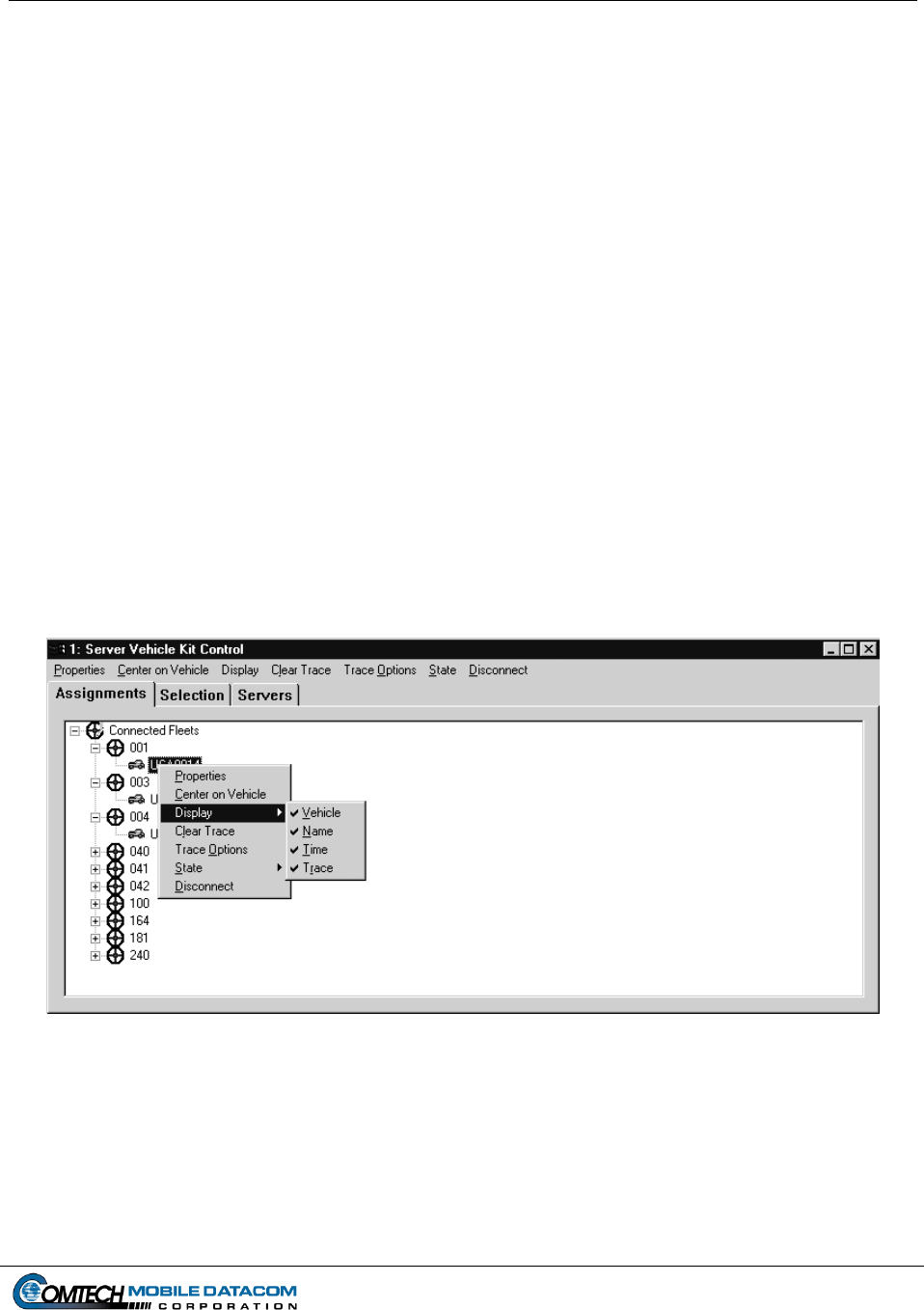
Contract No. DAAB15-99-D-0014 MTS Users Manual Revision: 1.9.1a
Page 6-15
6.6.5 Displaying and Hiding Individual Vehicles
There are times when a user may want to show or hide a single vehicle. To hide a
visible vehicle or show a hidden vehicle, follow the steps below:
(1) Right click on the map to get the pop up menu (Figure 6-8).
(2) Choose Select Vehicle.
(3) Click on the map with the mouse so that the Server Vehicle Kit Control
window pops up.
(4) Next, select the Assignments tab (see Figure 6-18).
(5) Once you see the Control Groups listed under the Assignments tab (Figure 6-
18), open a Control Group (e.g. 001,002,003, etc.) by clicking on the plus sign
(+) next to the group.
(6) Next, right click on the individual vehicle, and select Display Vehicle. If
the vehicle was already displayed it will be hidden. If it was hidden it will be
displayed. A hidden vehicle will have a on it indicating that it is hidden or
not displayed on the map.
Figure 6-18 Hiding and Showing an Individual Vehicle
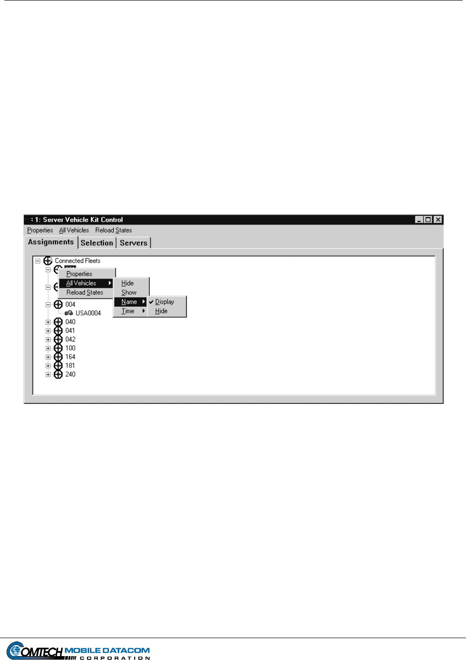
Contract No. DAAB15-99-D-0014 MTS Users Manual Revision: 1.9.1a
Page 6-16
6.6.6 Displaying and Hiding Name Labels for an Entire Control Group
(1) Right click on the map to get the pop up menu (Figure 6-8).
(2) Choose Select Vehicle.
(3) Click on the map with the mouse so that the Server Vehicle Kit Control
window pops up.
(4) Next, select the Assignments tab.
(5) Once you see the Control Groups listed under the Assignments tab, right click
on the fleet and select All Vehicles Name Display or All Vehicles
Name Hide (see Figure 6-19).
Figure 6-19 Hiding and Showing the Names of All Vehicles in a Fleet
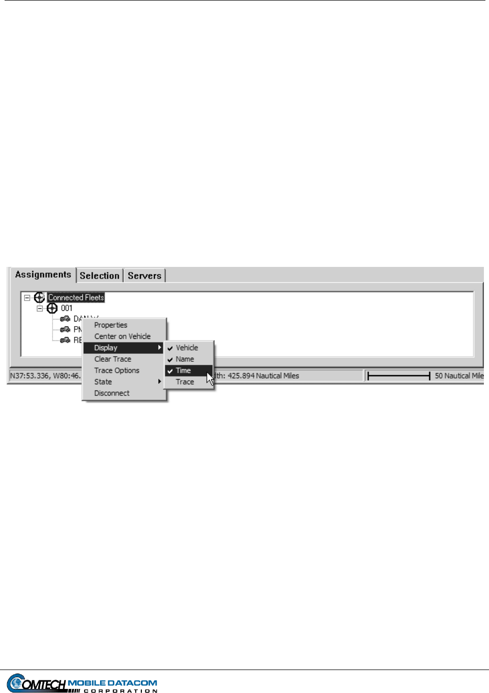
Contract No. DAAB15-99-D-0014 MTS Users Manual Revision: 1.9.1a
Page 6-17
6.6.7 Displaying and Hiding Report Time Labels for an Individual Vehicle
The map can display a tag next to the symbol on the map showing the time of the last
position and status report from that vehicle.
(1) Right click on the map to get the pop up menu (Figure 6-8).
(2) Choose Select Vehicle.
(3) Click on the map with the mouse so that the Server Vehicle Kit Control
window pops up.
(4) Next, select the Assignments tab (see Figure 6-20).
(5) Right click on a vehicle, and select Display Time, (see Figure 6-20). If the
time was not previously displayed, it will be. If the time was previously
displayed, it will be turned off.
Figure 6-20 Hiding and Showing the Position Report Time for a Vehicle
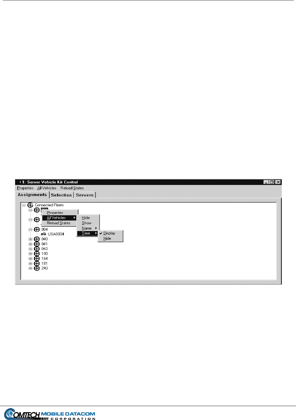
Contract No. DAAB15-99-D-0014 MTS Users Manual Revision: 1.9.1a
Page 6-18
6.6.8 Displaying and Hiding Report Time Labels for an Entire Control Group
The last report time for all vehicles in a Control Group can be displayed and hidden
via a single command in the Assignments tab of the Server Vehicle Kit Control
window. This saves the user from performing the command on each individual
vehicle in the fleet.
(1) Right click on the map to get the pop up menu (Figure 6-8).
(2) Choose Select Vehicle.
(3) Click on the map with the mouse so that the Server Vehicle Kit Control
window pops up.
(4) Next, select the Assignments tab (see Figure 6-21).
(5) Once you see the Control Groups listed under the Assignments tab right click
on the fleet name, and select All Vehicles Time Display or All
Vehicles Time Hide, (see Figure 6-21).
Figure 6-21 Hiding and Showing the Position Report for a Fleet of Vehicles
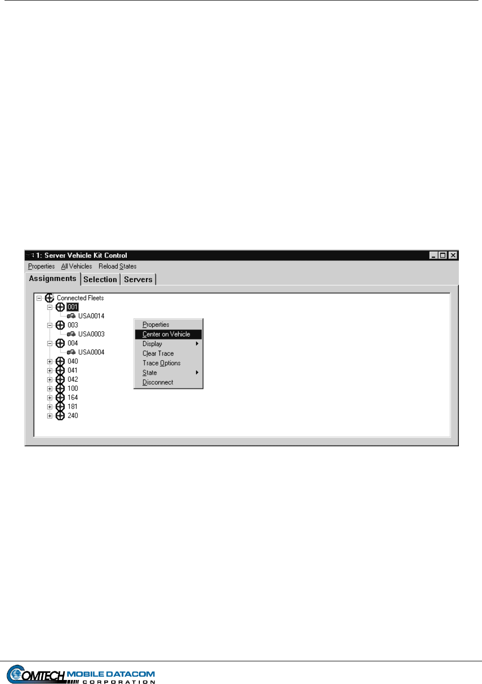
Contract No. DAAB15-99-D-0014 MTS Users Manual Revision: 1.9.1a
Page 6-19
6.6.9 Center on Vehicle
If a vehicle is not shown on the map, the Center on Vehicle function can be invoked
to find the vehicle. This will move the map to show the vehicle in the center.
(1) Right click on the map to get the pop up menu (Figure 6-8).
(2) Choose Select Vehicle.
(3) Click on the map with the mouse so that the Server Vehicle Kit Control
window pops up.
(4) Next, select the Assignments tab.
(5) Open the Control Group, right click on the vehicle you wish to find, and select
Center on Vehicle (see Figure 6-22).
Figure 6-22 Centering the Map on a Vehicle
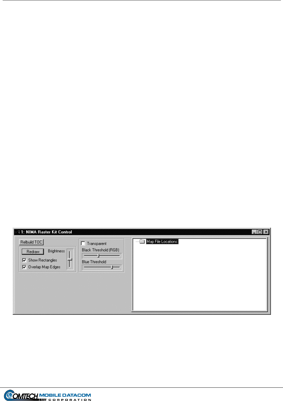
Contract No. DAAB15-99-D-0014 MTS Users Manual Revision: 1.9.1a
Page 6-20
6.7 NIMA CADRG Maps
Tracerlink includes the capability to view CADRG (Compressed ARC Digitized Raster
Graphics) maps. There are two ways in which CADRG maps can be viewed, directly
from a CD that has CADRG maps on it, or via the computer’s hard drive. Viewing from
a CD is recommended when a user only needs to see CADRG maps for a short period of
time, or if the CD will be permanently available to the user. Viewing CADRG maps
from the hard drive require the user to load (or copy) the CADRG maps to the hard drive.
Viewing the maps from the hard drive is recommended for users who need to see
CADRG maps of an area but will not have permanent/constant access to a CD with the
CADRG maps.
6.7.1 Viewing CADRG Maps from a Compact Disk
To configure your TracerLink Configuration to read NIMA CADRG maps directly
from a compact disk follow the steps below:
(1) Insert a CD (which has NIMA CADRG maps on it) into the Control Station
laptop’s CD player.
(2) Open the NIMA Raster Kit Control window by using the Kit Bar. To open the
Kit Bar slowly slide the cursor off the right side of the map. When you approach
the edge of the map the Kit Bar will appear. Select the CADRG button on the Kit
Bar. After you have selected this button, NIMA Raster Kit Control will open (see
Figure 6-23).
Figure 6-23 NIMA Raster Kit Control Window
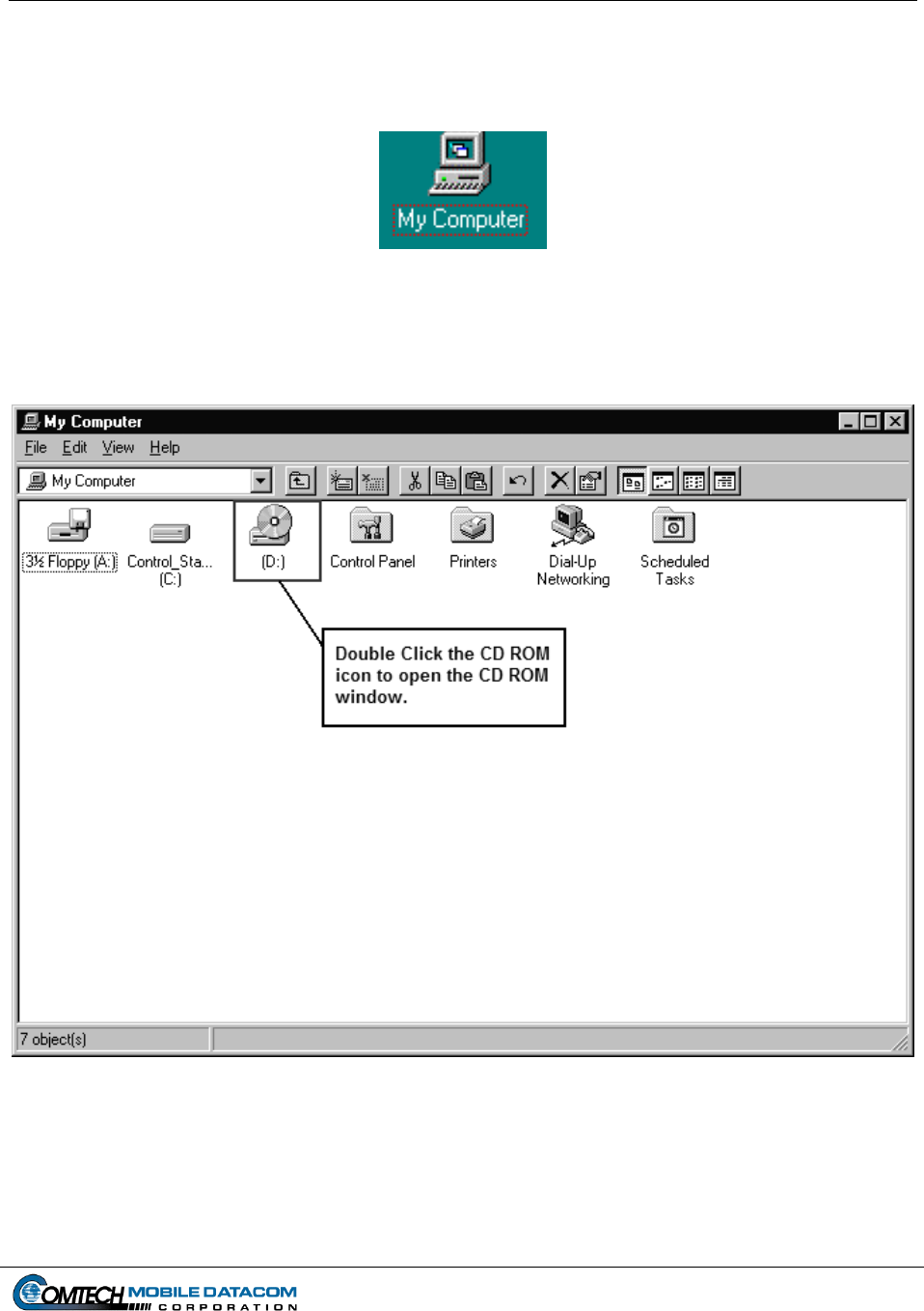
Contract No. DAAB15-99-D-0014 MTS Users Manual Revision: 1.9.1a
Page 6-21
(3) Once you have the NIMA Raster Kit Control window, you will need to go to the
appropriate folder on the CD where the NIMA CADRG maps are stored. To view
what is on the CD double click on the My Computer icon, (see Figure 6-24).
Figure 6-24 My Computer Icon
(4) The My Computer window should open, (see Figure 6-25).
Figure 6-25 My Computer Window
(5) Double click on the CD ROM icon (see Figure 6-25). The CD ROM drive on the
Control Station laptop will typically be labeled with the letter “D”.
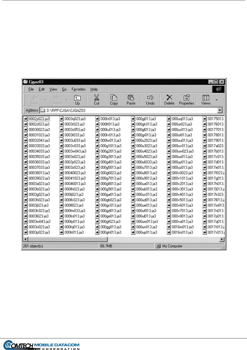
Contract No. DAAB15-99-D-0014 MTS Users Manual Revision: 1.9.1a
Page 6-22
(6) Once you have opened the CD ROM, you will need to find the maps. Every CD
ROM may have a slightly different filing method of storing the maps. Therefore
you will need to be able to recognize when you have found the CADRG map
files. Individual CADRG map files will be saved as a group into one folder. The
folder containing the map files may be located several levels within the file
structure. In other words you may need to double click on several folders before
you find the map files. An example of a folder of CADRG files is included in
Figure 6-26. As Figure 6-26 illustrates there can be hundreds of CADRG maps
files in one folder.
Figure 6-26 NIMA CADRG Map Files
(7) Once you have found the individual map files, go to the Edit menu option.
Choose the Select All option. This will highlight all the files in the window.
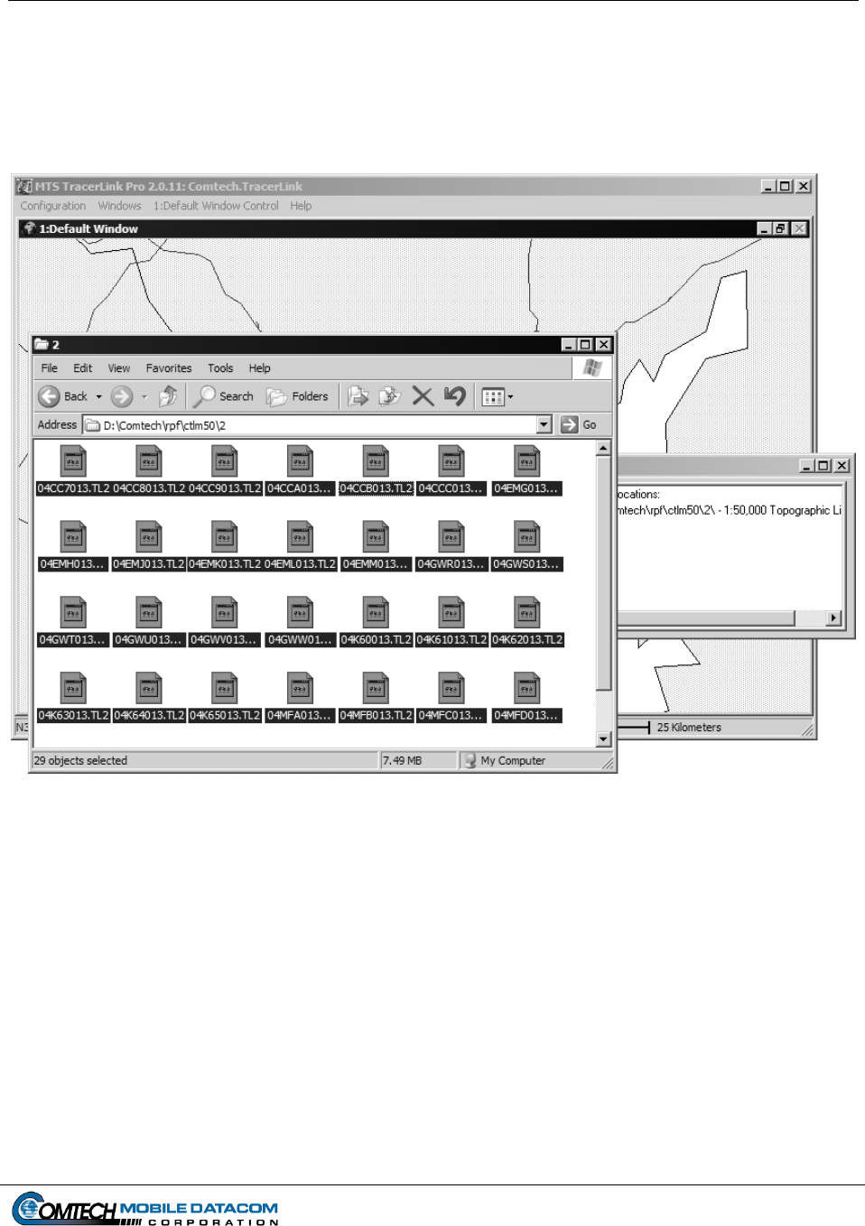
Contract No. DAAB15-99-D-0014 MTS Users Manual Revision: 1.9.1a
Page 6-23
(8) Maximize your TracerLink Map Viewer window if it was minimized. Now you
should have at least three windows open and maximized (visible) simultaneously,
the Map Viewer, the CADRG Map files, and the NIMA Raster Control Kit
window (see Figure 6-27).
Figure 6-27 TracerLink Map Viewer open with the CADRG Map Files Folder Open
(9) Click your mouse on the selected files. Then drag the files on to the map. A
cross or plus sign (+) will appear next to your arrow (cursor) indicating that you
are about to add maps to the configuration. Let go of the mouse.
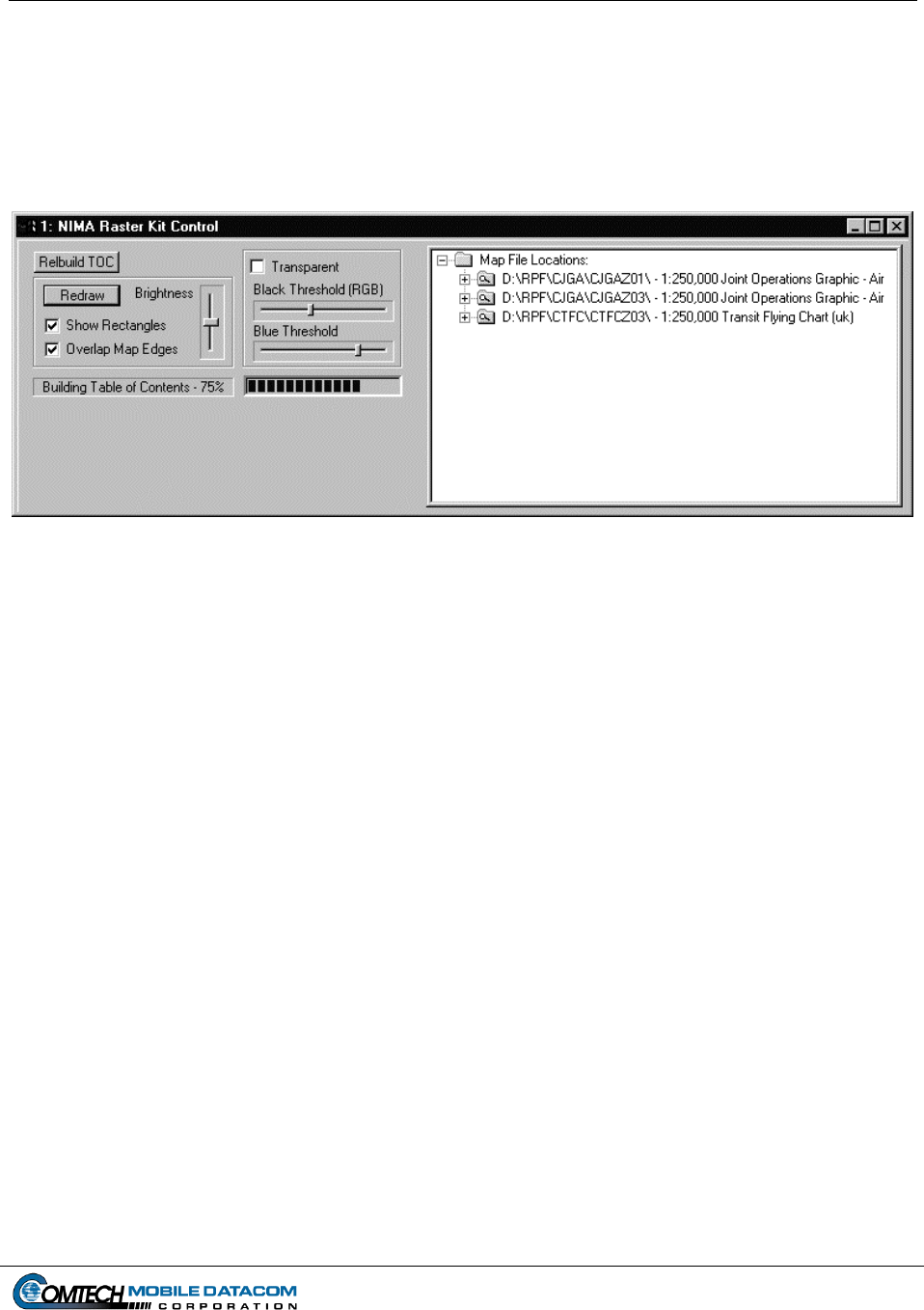
Contract No. DAAB15-99-D-0014 MTS Users Manual Revision: 1.9.1a
Page 6-24
(10) The maps should begin loading into the NIMA Raster Control Kit window. If
you want to verify that it is loading correctly, check the NIMA Raster Control
Kit. You should see a blue bar next to the words “Building a Table of Contents,”
(see Figure 6-28). If this blue bar does not appear you are not loading the maps
correctly.
Figure 6-28 NIMA Raster Kit Control Window Showing the Maps Loading
(11) It is now possible to close the CADRG Map folder and the NIMA Raster Kit
Control window (unless you want to load more maps from the CD).
NOTE: When reading directly from a CD the maps are not saved to the hard drive.
Before exiting TracerLink, you will be asked if you want to save the configuration. If
you do save the configuration, you will need the CD to view the CADRG maps in
your subsequent sessions of TracerLink. If you want to save the configuration and
not use the CD in the future, you will need to load the maps on the computer (see next
section).
6.7.2 Loading NIMA CADRG Maps to the Computer’s Hard Drive
The section above described how to view NIMA CADRG maps from a CD. Viewing
maps directly from a CD is good for temporary situations where you will not need the
maps for a long period of time. If you believe that you will need the NIMA CADRG
maps for a long time, you should load the maps to the appropriate map folder on the
hard drive. In order to do this you will need a CD with NIMA CADRG maps on it.
To load the maps to the hard drive follow steps below:
(1) Double click the My Computer icon, (see Figure 6-24).
(2) Double click on the CD ROM icon (see Figure 6-25). The CD ROM drive on the
Control Station laptop will typically be labeled with the letter “E.”
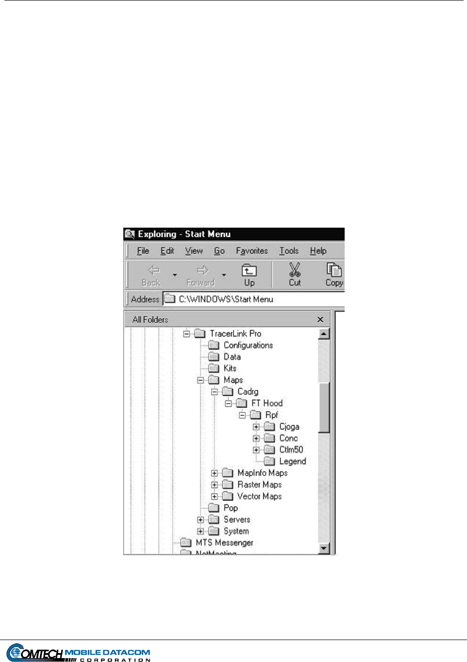
Contract No. DAAB15-99-D-0014 MTS Users Manual Revision: 1.9.1a
Page 6-25
(3) Once you have opened the CD ROM, you will need to find the maps. Every CD
ROM may have a slightly different filing method of storing the maps. Therefore
you will need to be able to recognize when you have found the CADRG map
files. Individual CADRG map files will be saved as a group into one folder. The
folder containing the map files may be located several levels within the file
structure. In other words you may need to double click on several folders before
you find the map files. An example of a folder of CADRG files is included in
Figure 6-26.
(4) Open Microsoft Windows Explorer, and then find the CADRG Maps folder of
TracerLink Pro. The Maps folder can be found in the following directory path
(see Figure 6-29):
C:\Program Files\Miletus Associates\TracerLink Pro\Maps\CADRG
Figure 6-29 TracerLink CADRG Map Folder Location in Windows Explorer
(5) Drag the CADRG Maps folder on the CD into the TracerLink Pro Maps CADRG
folder. This will copy the maps from the CD onto the hard drive.

Contract No. DAAB15-99-D-0014 MTS Users Manual Revision: 1.9.1a
Page 6-26
6.7.3 Viewing CADRG Maps Directly from the Hard Drive
Once the maps are copied over to the hard drive, you can configure the TracerLink to
view the NIMA CADRG maps from your hard drive rather than the CD. The steps
that follow are the same as reading the maps from the CD.
(1) Find the CADRG Maps folder (on your hard drive) that you want to see in your
TracerLink Map Viewer. Once you have opened the folder and you can see the
CADRG map files (see Figure 6-26) go to the Edit menu option. Choose the
Select All option. This will highlight all the files in the window.
(2) Open the NIMA Raster Kit Control window by using the Kit Bar as seen in
Figure 6-11. To open the Kit Bar slowly slide the cursor off the right side of the
map. When you approach the edge of the map the Kit Bar (Figure 6-11) will
appear. Select the CADRG button on the Kit Bar. After you have selected this
button, NIMA Raster Kit Control will open, (see Figure 6-23).
(3) Maximize your TracerLink Map Viewer window if it was minimized. Now you
should have at least three windows open and maximized (visible) simultaneously,
the Map Viewer, the CADRG Map files, and the NIMA Raster Control Kit
window (see Figure 6-27).
(4) Click your mouse on the selected NIMA CADRG files. Then drag the files on to
the map. A cross or plus sign (+) will appear next to your arrow (cursor)
indicating that you are about to add maps to the configuration. Let go of the
mouse.
(5) The maps should begin loading into the NIMA Raster Control Kit window. If
you want to verify that it is loading correctly, check the NIMA Raster Control Kit.
You should see a blue bar next to the words “Building a Table of Contents,” (see
Figure 6-28). If this blue bar does not appear you are not loading the maps
correctly.
(6) Save the TracerLink configuration.
6.8 Configuring TracerLink to Show Specific NIMA Maps
The Select NIMA Raster Kit allows the user to select specific maps from a group of
NIMA maps. The user views only the maps selected from the CD-ROM or Hard Drive.
To enable the Select NIMA Raster Kit function:
(1) Load maps from a CD-ROM or the Hard Drive.
(2) Create a destination folder. See example below for instructions on how to create a
destination folder.
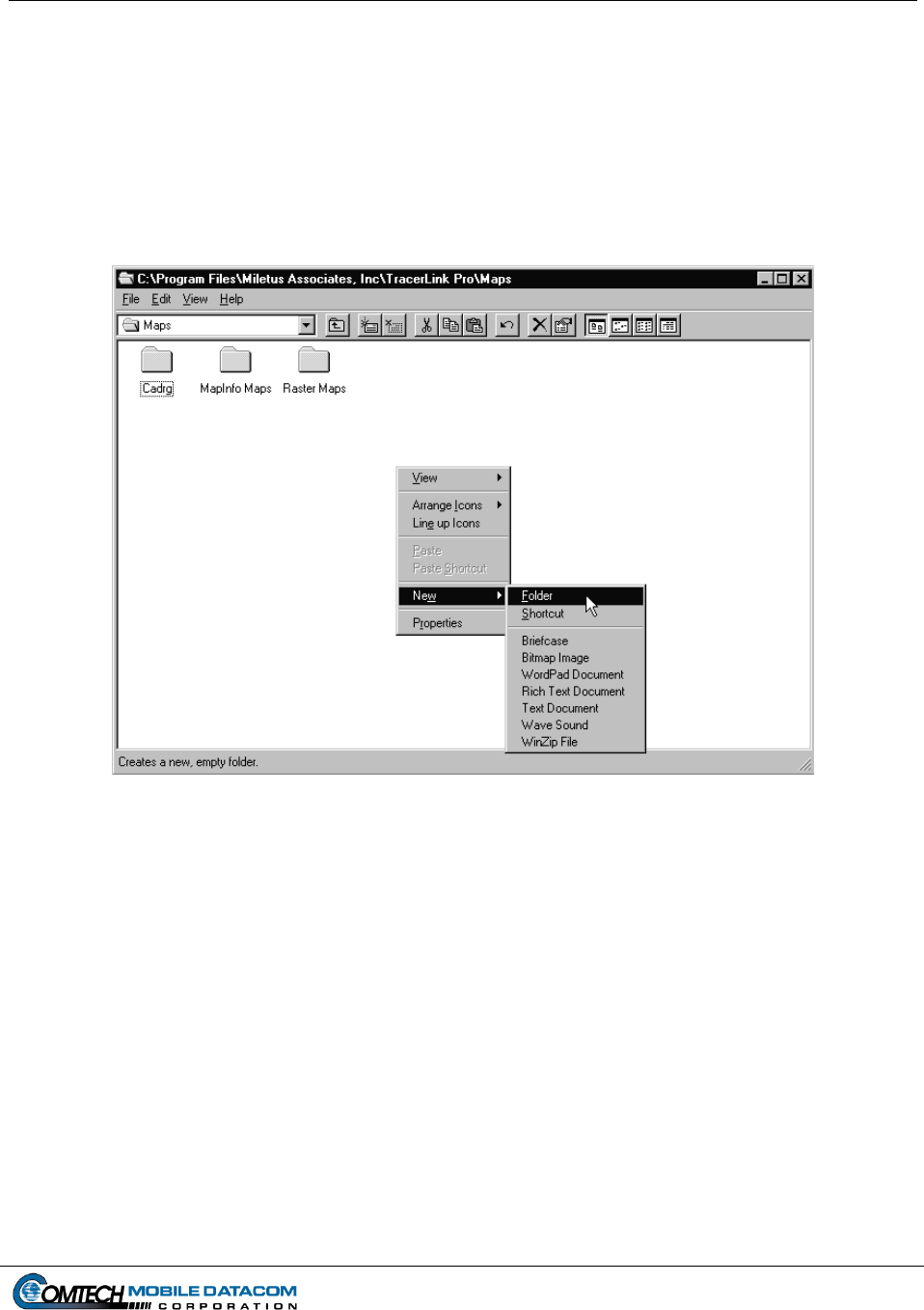
Contract No. DAAB15-99-D-0014 MTS Users Manual Revision: 1.9.1a
Page 6-27
(a) Open Microsoft Windows Explorer (see Figure 6-30).
(b) Double click on the icon for the hard drive “C” to view contents.
(c) Double click on the Program Files folder icon to view contents.
(d) Double click on the Miletus Associates folder icon to view contents.
(e) Double click on the TracerLink folder icon to view contents.
(f) Double click on the Maps folder to view its contents. Your Windows
Explorer should look similar to Figure 6-30.
Figure 6-30 Creating a Destination Folder
(g) Right click your mouse on the right pane of Windows Explorer.
(h) Select New, then Folder. A New Folder will be created. Type a name for the
new folder.
(3) Select the TracerLink Pro window and right click on the map, choose the Select
NIMA Raster Kit option from the Pop-Up menu. The Cursor will change to a
globe with an arrow.
(4) Use this cursor to select map area.
(5) Open the NIMA Raster Kit Control window (see Figure 6-28).
(6) Press Copy Selection button on the NIMA Raster Kit Control window. The user
will be prompted to copy to the destination folder.
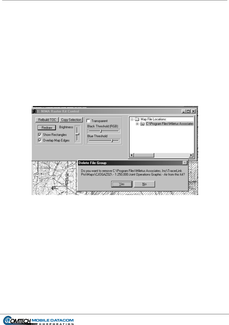
Contract No. DAAB15-99-D-0014 MTS Users Manual Revision: 1.9.1a
Page 6-28
(7) Find the destination folder created in Step 2.G above.
(8) Remove map file group from the NIMA Raster Kit Control window (see Figure 6-
31). On the NIMA Raster Kit Control window, select the map file group to be
removed. Right click on the map file group folder. Click on Remove File Group.
The Delete File Group window will open. Click Yes.
NOTE: The method of loading new map configurations to the MTS systems are
as follows:
• Control Stations will be loaded by using a pre-configured CD Rom
inserted into the Control Stations internal CD slot.
• V2 computers will be loaded by using a PCMCIA hard drive with the pre
-configured map files loaded.
Figure 6-31 Remove Map Files
(9) Open the newly created destination folder.
(10) Select and drag the files in the destination folder to the Map Viewer until you see
a cross (+) symbol. Release the mouse and the maps will load into the Map
Viewer.
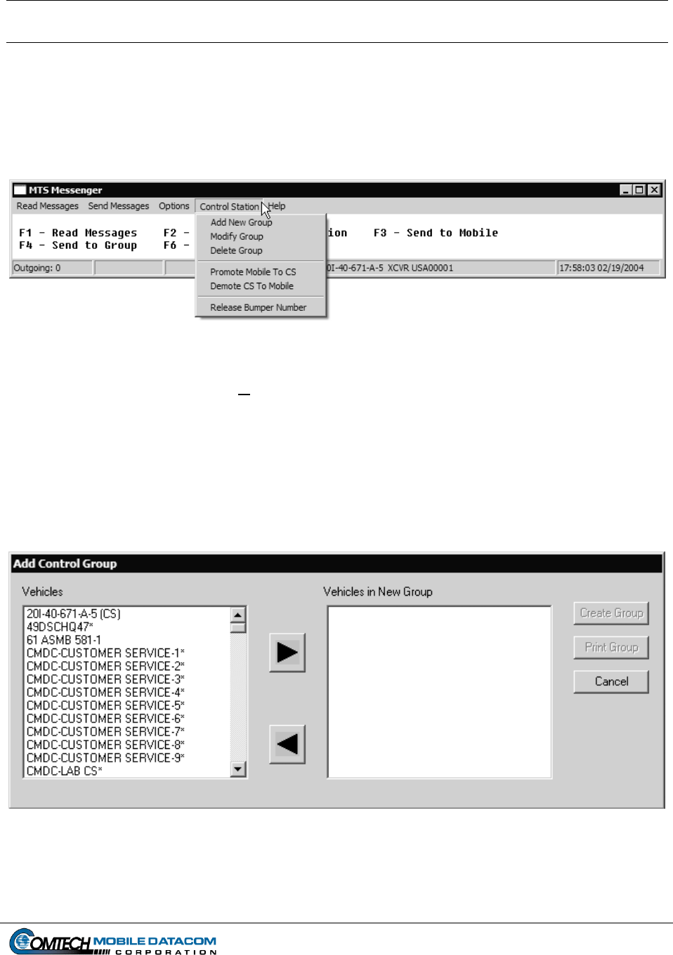
Contract No. DAAB15-99-D-0014 MTS Users Manual Revision: 1.9.1a
Page 7-1
7. Control Station Functions
7.1 The Control Station Menu
The Control Station menu (Figure 7-1) gives the user of a Control Station the ability to
create, modify, and delete control groups. Each control group consists of one or more
vehicles and is assigned a unique numeric identifier.
Figure 7-1 Control Station Menu
7.1.1 Control Station Add New Group
To create a new Control Group, select Add New Group from the MTS Messenger
Control Station menu. MTS units can be added to the new group. Mobile units will
be removed from their existing group and added to the new group while Control
Stations will be added to the new group and remain in their existing group. This
allows the Control Station operator, System Administrator, or CSSAMO the ability to
customize control groups to suit the mission (see Figure 7-2).
Figure 7-2 Add Control Group Dialog
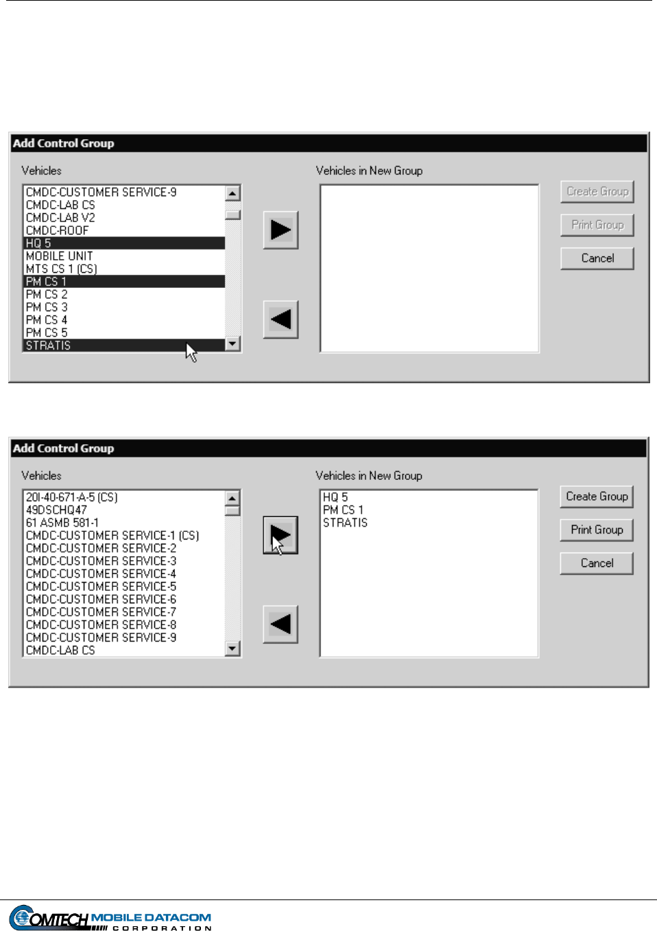
Contract No. DAAB15-99-D-0014 MTS Users Manual Revision: 1.9.1a
Page 7-2
(1) Select Control Station Add New Group menu option.
(2) To add a vehicle, the Control Station operator should select one or more vehicles
from the list on the left. To select more than one vehicle the operator can hold
down the Ctrl key and click on individual units (see Figures 7-3 and 7-4).
Figure 7-3 Selecting several units
Figure 7-4 Several units added to the new group
The operator may also select one unit, hold down the Shift key and select another unit, all
units between the two selected units in the list will then be selected (see Figures 7-5 and 7-6).
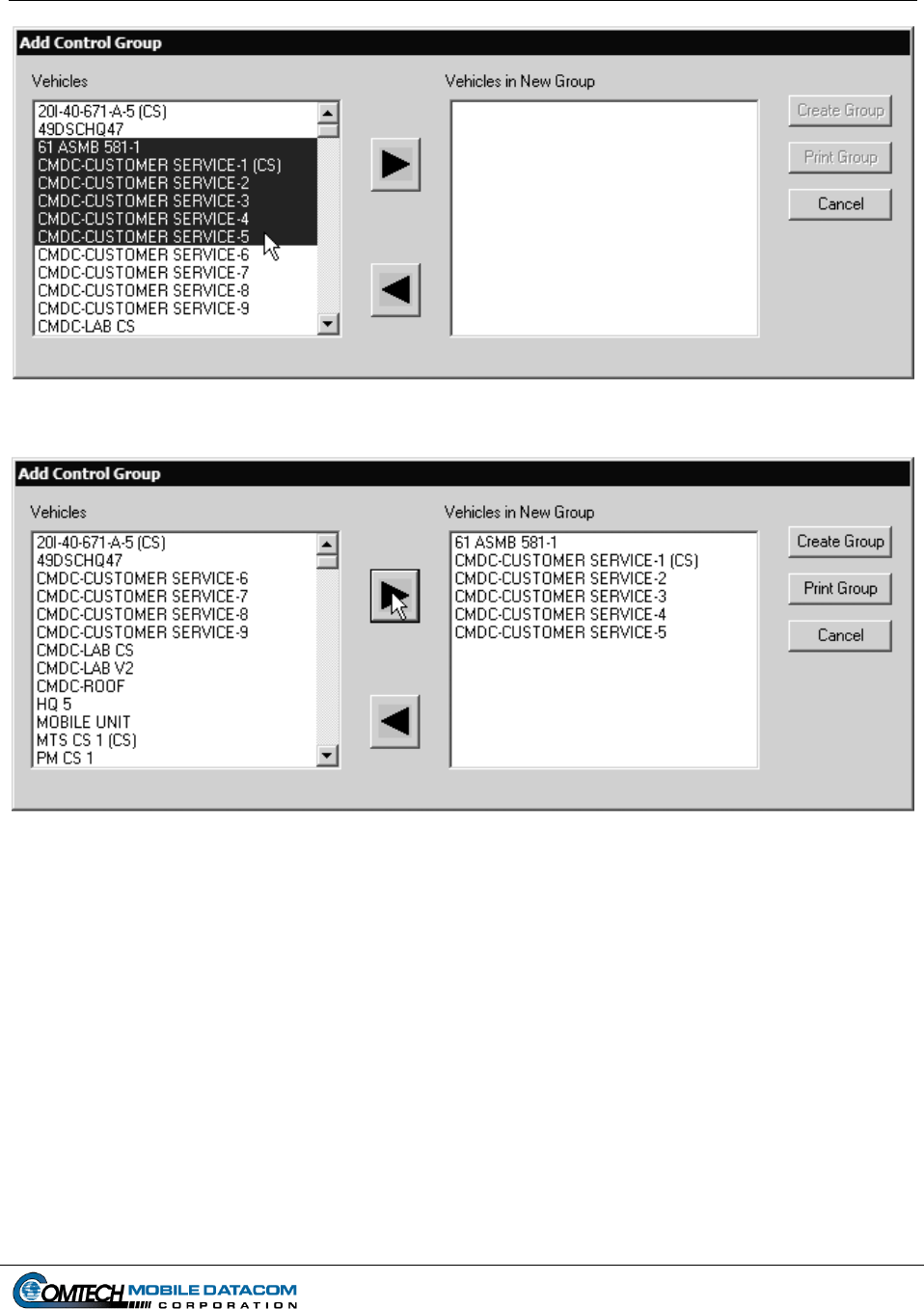
Contract No. DAAB15-99-D-0014 MTS Users Manual Revision: 1.9.1a
Page 7-3
Figure 7-5 Selecting a range of units
Figure 7-6 Range of units added to new group
(3) Once one or more vehicles have been selected press the ► button to move the
vehicles to the new group. The ◄ button can be used to remove vehicles from
the new group.
(4) Before creating the Control Group, the Control Station operator can print the
pending Control Group, by pressing the Print Group button.
(5) Once all vehicles have been specified for the pending group, the user presses the
Create Group button. The user can cancel creation of a group by pressing the
Cancel button.
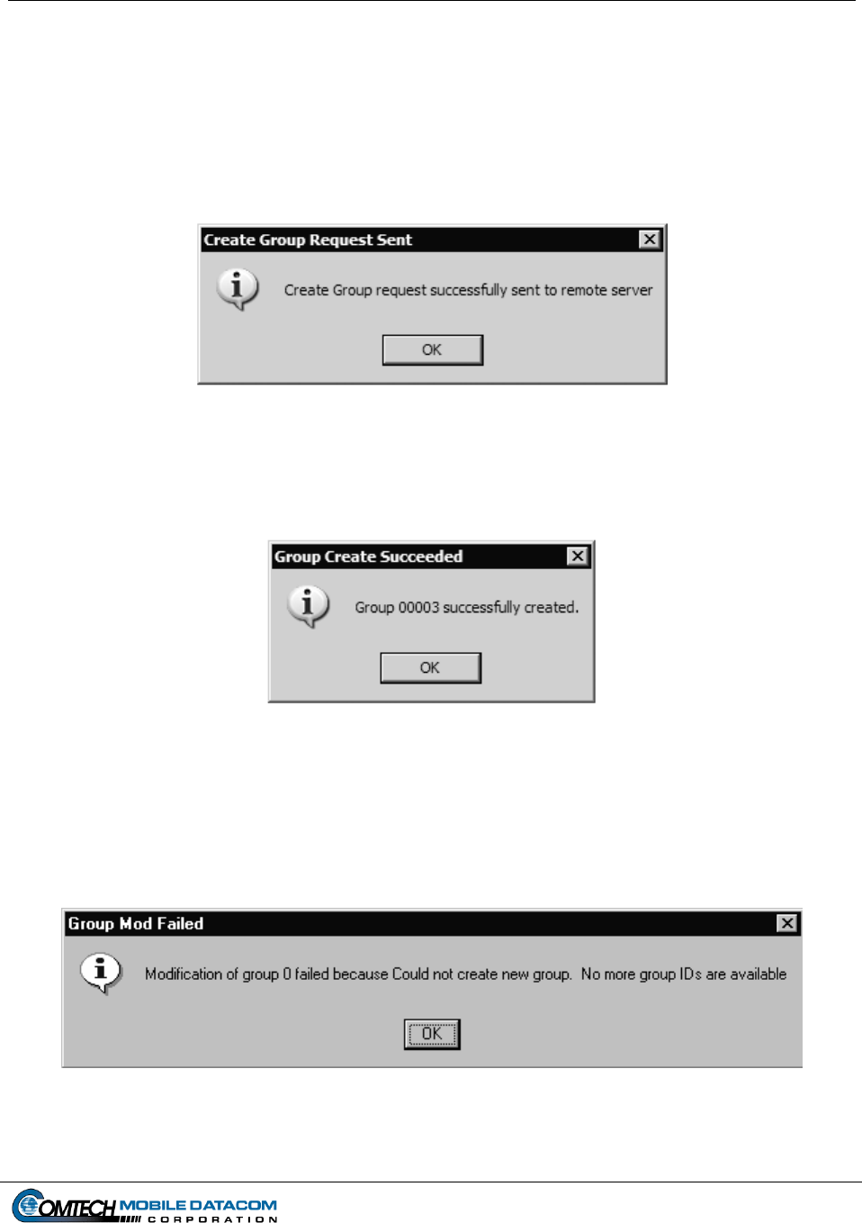
Contract No. DAAB15-99-D-0014 MTS Users Manual Revision: 1.9.1a
Page 7-4
NOTE: The maximum size for a Control Group is 11,000 vehicles. If a user
attempts to create a group that exceeds 11,000 vehicles, MTS Messenger will
issue an error message. The maximum number of simultaneous Control
Groups is 255. Units not in service should not be assigned a Control Group.
(6) After the user presses the Create Group button, the following messages are
displayed:
Figure 7-7 Sent Create Group Request Message
When the group is successfully created the user will receive the following message (Figure 7-
8).
Figure 7-8 Added to Group Message
If MTS Messenger is unable to create a group because there are already the maximum
number of groups create, the following message box (Figure 7-9) will be displayed and the
user will have to delete an existing group before the new group can be created (see Section
7.1.3).
Figure 7-9 Create Group Failed - Too many groups
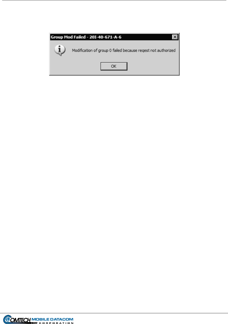
Contract No. DAAB15-99-D-0014 MTS Users Manual Revision: 1.9.1a
Page 7-5
Finally, if the user has been demoted to a mobile unit (see Section 7.1.5) while creating the
group the user will receive a message indicating that the request was not authorized (see
Figure 7-10).
Figure 7-10 Create Group Not Authorized
NOTE: MTS Messenger learns of vehicles, their positions, and any new groups
through the various messages. Because of this, there will be a lag of about five
minutes between the time a unit is added to a group and the time a unit can see and
send messages to other units in its group. MTS Messenger will only allow a unit to
see units in its Control Group(s). Mobile units can only be in a single Control Group;
therefore, if multiple requests for Control Groups are received and the same unit is in
the requests, the unit is actually added to the Control Group of the last received
request. Control Stations can be in more than one group.
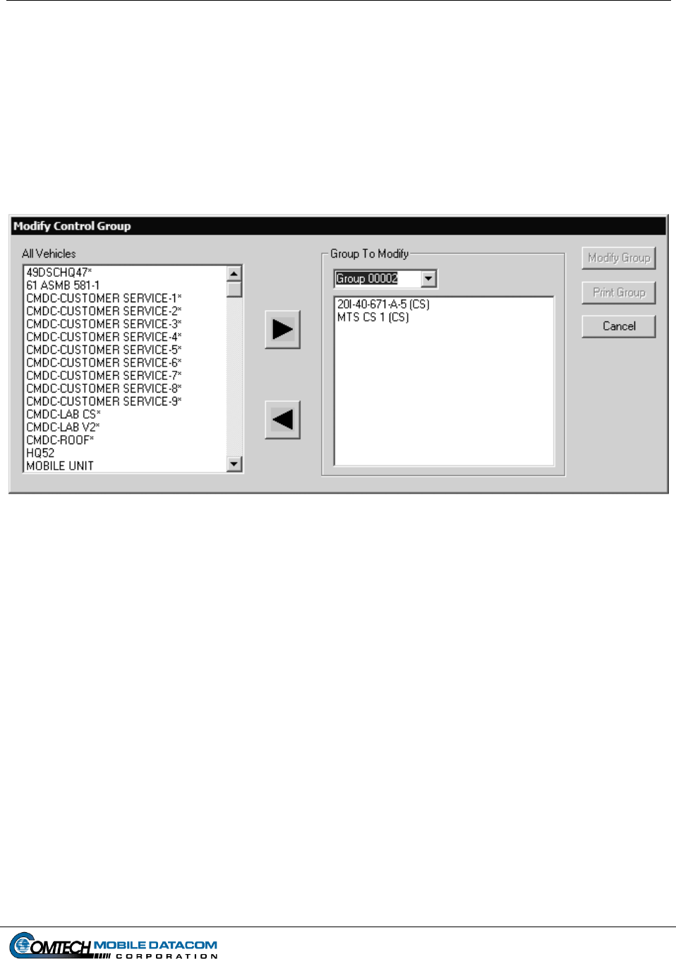
Contract No. DAAB15-99-D-0014 MTS Users Manual Revision: 1.9.1a
Page 7-6
7.1.2 Control Station Modify Group
To modify an existing group, select Modify Groups from the MTS Messenger
Control Station menu. MTS units can be moved from one group to another. This
allows the Control Station operator, System Administrator, or CSSAMO the ability to
customize control groups to suit the mission.
(1) Select Control Station Modify Group, the Modify Control Group dialog box
will appear (see Figure 7-11).
Figure 7-11 Modify Control Group Dialog
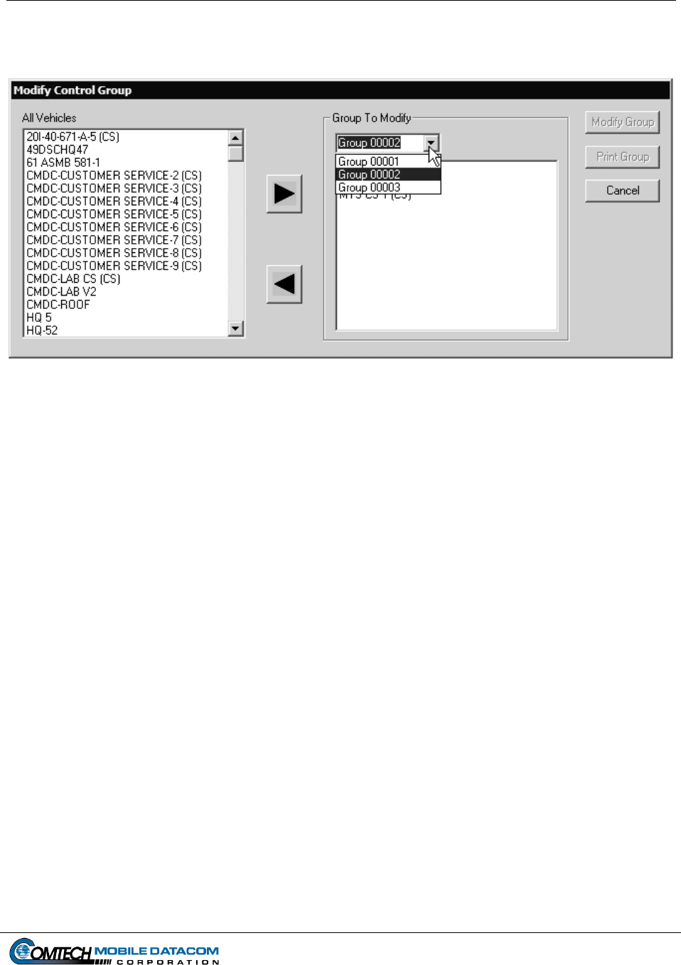
Contract No. DAAB15-99-D-0014 MTS Users Manual Revision: 1.9.1a
Page 7-7
(2) Select the control group to be modified from the drop down box on the right (see
Figure 7-12).
Figure 7-12 Select a Control Group to Modify
(3) Select vehicles and press the ► and ◄ buttons to add and remove vehicles from
the selected group. The shift and Ctrl key can be used to select multiple vehicles
as described in 7.1.1.
(4) Before modifying the Control Group, the Control Station operator can print the
pending Control Group, by pressing the Print Group button.
(5) Once all vehicles have been specified for the pending group, the user presses the
Modify Group button. The user can cancel modification of a group by pressing
the Cancel button.
NOTE: The maximum size for a Control Group is 11,000 vehicles. If a user
attempts to create a group that exceeds 11,000 vehicles, MTS Messenger will
issue an error message. Units not in service should not be assigned a Control
Group.
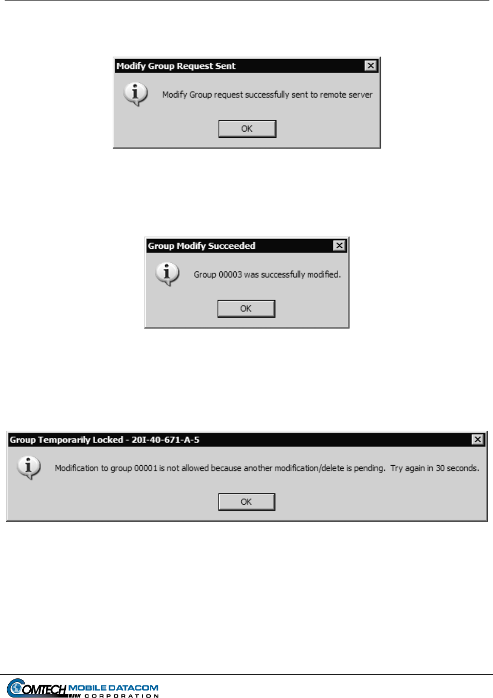
Contract No. DAAB15-99-D-0014 MTS Users Manual Revision: 1.9.1a
Page 7-8
(6) After the user presses the Modify Group button, the following messages are
displayed (see Figure 7-13):
Figure 7-13 Sent Modify Group Request Message
When the group is successfully modified the user will receive the following message (Figure
7-14).
Figure 7-14 Added to Group Message
If MTS Messenger is unable to modify the group because the group is currently being
modified the following message box (Figure 7-15) will be displayed and the user can begin
the process of creating the group again.
Figure 7-15 Group Not Modified Message
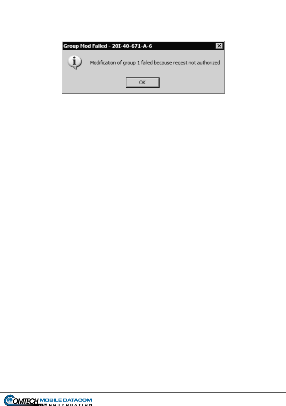
Contract No. DAAB15-99-D-0014 MTS Users Manual Revision: 1.9.1a
Page 7-9
Finally, if the user has been demoted to a mobile unit (see Section 7.1.5) while modifying the
group the user will receive a message indicating that the request was not authorized (see
Figure 7-16).
Figure 7-16 Modification of Group Not Authorized
NOTE: MTS Messenger learns of vehicles, their positions, and any new groups
through the various messages. Because of this, there will be a lag of about five
minutes between the time a unit is added to a group and the time a unit can see and
send messages to other units in its group. MTS Messenger will only allow a unit to
see units in its Control Group(s). Mobile units can only be in a single Control Group;
therefore, if multiple requests for Control Groups are received and the same unit is in
the requests, the unit is actually added to the Control Group of the last received
request. Control Stations can be in more than one group.
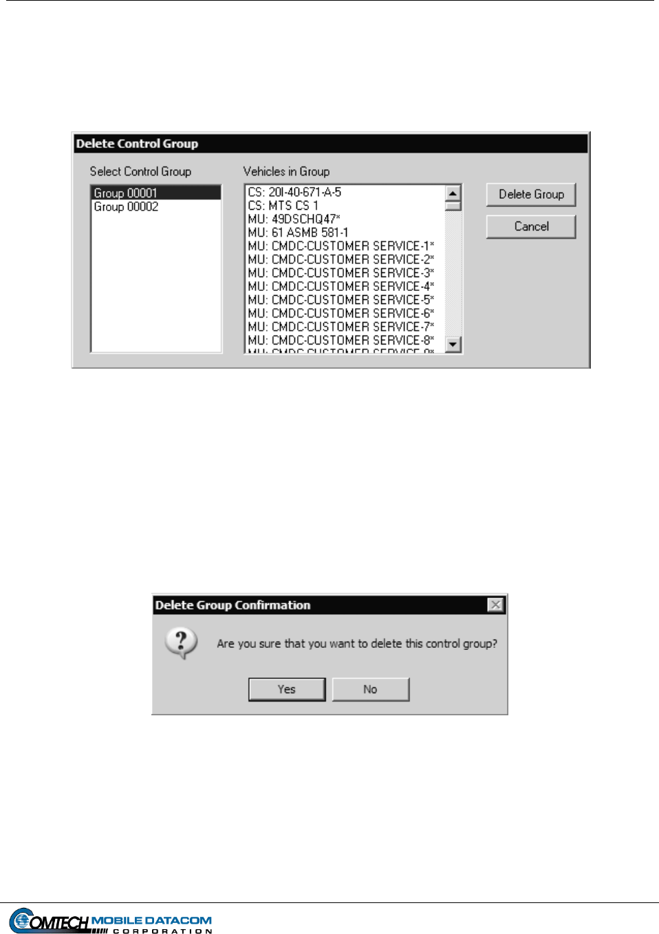
Contract No. DAAB15-99-D-0014 MTS Users Manual Revision: 1.9.1a
Page 7-10
7.1.3 Control Station Delete Group
To delete an existing group, select Delete Group from the MTS Messenger Control
Station menu. This allows the Control Station operator, System Administrator, or
CSSAMO the ability to delete a group that is no longer needed.
Figure 7-17 Delete Control Group
The Select Control Group list box shows all of the groups. For a selected Control
Group, the Vehicles in Group list box identifies all the vehicles in a selected group.
(1) If the Control Station user wishes to delete a Control Group, select a group in the
Select Control Group list box (Figure 7-17) and press the Delete Group button.
(2) The operator will be asked to confirm that they wish the group to be deleted (see
Figure 7-18).
Figure 7-18 Confirm Group Deletion
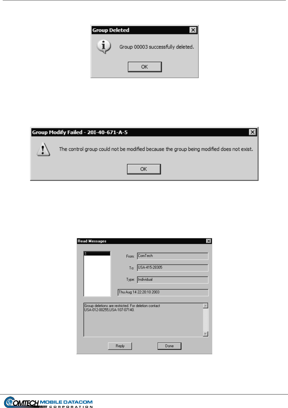
Contract No. DAAB15-99-D-0014 MTS Users Manual Revision: 1.9.1a
Page 7-11
If the group is successfully deleted a window will be displayed (see Figure 7-19).
Figure 7-19 Group Successfully Deleted
Otherwise a message will be displayed indicating that the delete request failed (see Figure 7-
20).
Figure 7-20 Delete Request Failed
Also, if delete group requests have been restricted the user will receive a message from the
server indicating that the group delete request was denied and what unit to contact to delete
the group (see Figures 7-21 and 7-22).
Figure 7-21 Delete Request Denied
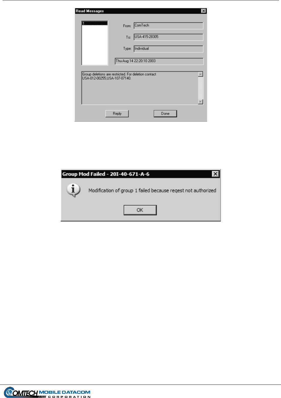
Contract No. DAAB15-99-D-0014 MTS Users Manual Revision: 1.9.1a
Page 7-12
Figure 7-22 Delete Group Restricted
Finally, if the user has been demoted to a mobile unit (see Section 7.1.5) while selecting what
group to delete the user will receive a message indicating that the request was not authorized
(see Figure 7-23).
Figure 7-23 Delete Group Not Authorized
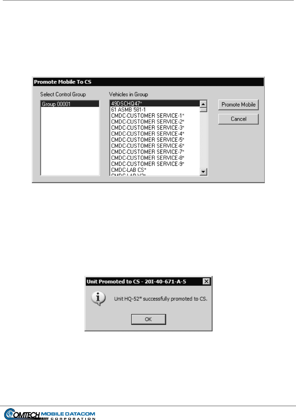
Contract No. DAAB15-99-D-0014 MTS Users Manual Revision: 1.9.1a
Page 7-13
7.1.4 Control Station Promote Mobile to CS
Under certain situations a Mobile Unit may need to be promoted to Control Station
status. To promote a unit follow these steps:
(1) Select Control Station Promote Mobile to CS on the MTS Messenger menu
bar (see Figure 7-24).
Figure 7-24 Promote Mobile to CS Dialog Box
(2) Select a Control Group.
(3) Identify and select the unit within the Control Group that should be promoted.
Press the Promote Mobile button.
(4) A window will be displayed that confirms that the mobile unit was promoted to a
control station (see Figure 7-25). The mobile unit will be notified of its new
status in about five minutes.
Figure 7-25 Promotion Confirmation
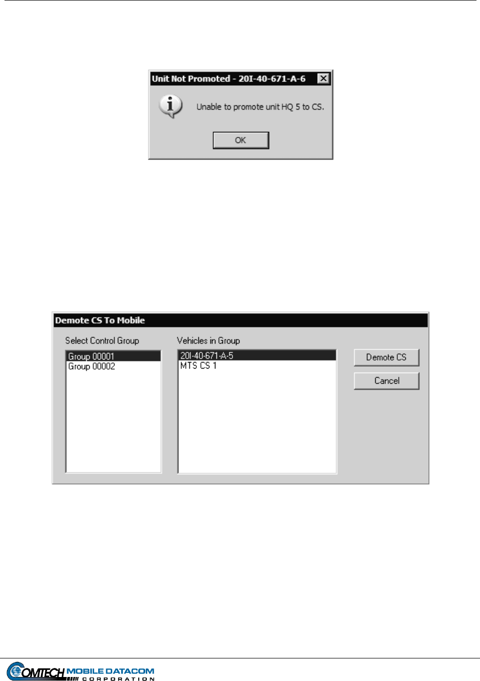
Contract No. DAAB15-99-D-0014 MTS Users Manual Revision: 1.9.1a
Page 7-14
If the user attempts to promote a unit that has already been promoted or if the user has been
demoted to a mobile unit while choosing what unit to promote a message will be displayed
indicating that the promotion request failed (see Figure 7-26).
Figure 7-26 Promotion Request Failed
7.1.5 Control Station Demote CS to Mobile
Under certain situations a Control Station may need to be demoted to Mobile Unit
status. To demote a unit follow these steps:
(1) Select Control Station Demote CS to Mobile on the MTS Messenger menu
bar. (See Figure 7-27).
Figure 7-27 Demote CS to Mobile Dialog Box
(2) Select a Control Group.
(3) Identify and select the unit within the Control Group that should be demoted.
Press the Demote CS button (Figure 7-27)
NOTE: If the Control Station is assigned to more that one group, it cannot be demoted.
The unit MUST be deleted from all groups. The Modify Control Groups function
allows the Administrator to delete the unit from its group.
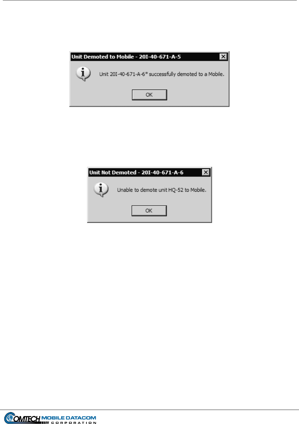
Contract No. DAAB15-99-D-0014 MTS Users Manual Revision: 1.9.1a
Page 7-15
(4) A window will be displayed that confirms that the mobile unit was demoted to a
mobile unit (see Figure 7-28). The mobile unit will be notified of its new status in
about five minutes.
Figure 7-28 Demotion Confirmation
If the user attempts to demote a unit that has already been demoted or if the user has been
demoted to a mobile unit while choosing what unit to demote a message will be displayed
indicating that the demotion request failed (see Figure 7-29).
Figure 7-29 Demotion Request Failed
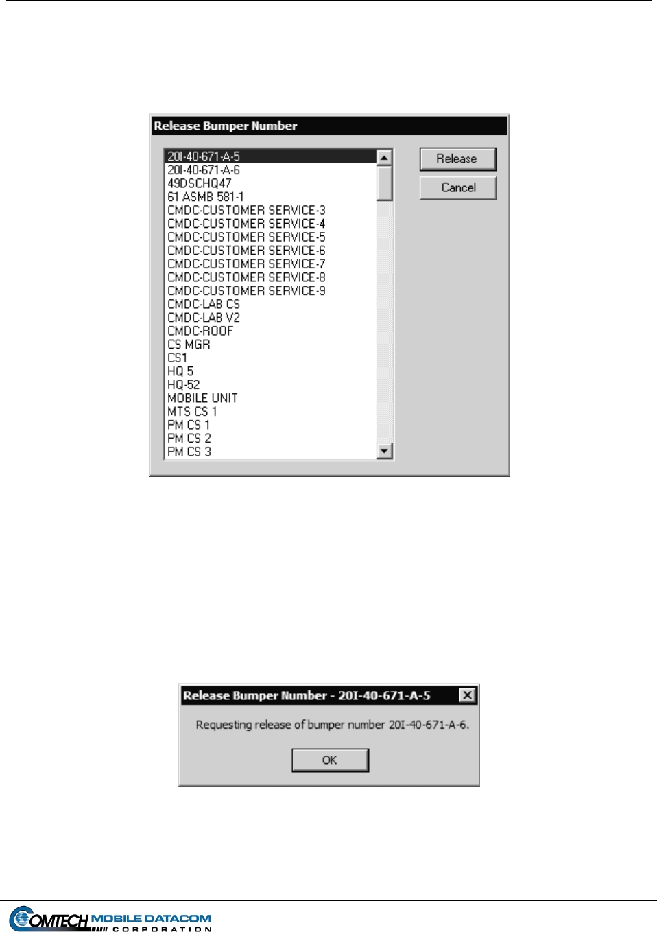
Contract No. DAAB15-99-D-0014 MTS Users Manual Revision: 1.9.1a
Page 7-16
7.1.6 Control Station Release Bumper Number
(1) To release a bumper number that is assigned to a unit select the Release Bumper
Number option on the Control Station menu (see Figure 7-30).
Figure 7-30 Release Bumper Number Dialog
(2) Select the Bumper Number that you wish to delete.
(3) Press the Cancel button to exit the dialog.
(4) Press the OK button.
(5) You will see a confirmation message that the request was sent (see Figure 7-31).
Figure 7-31 Release Bumper Number Request Sent
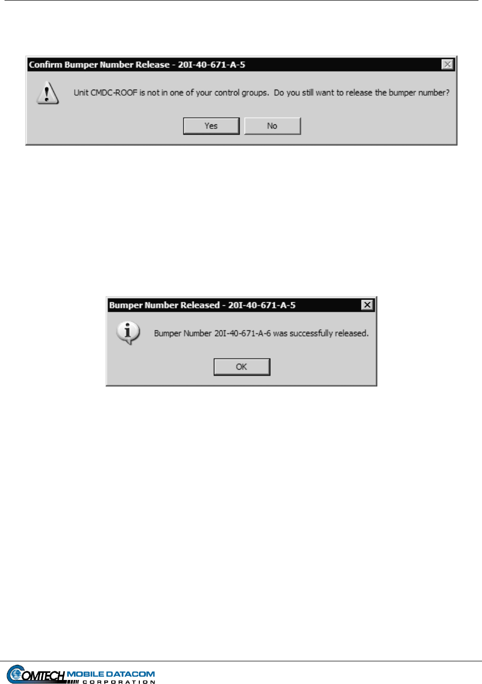
Contract No. DAAB15-99-D-0014 MTS Users Manual Revision: 1.9.1a
Page 7-17
(6) If you have selected a Bumper Number that belongs to a vehicle that is not in one
of your control groups you will be asked to confirm the request (see Figure 7-32).
Figure 7-32 Unit not in Group Warning
(7) Press the Yes button if you still want to release the bumper number.
(8) If you press the No button the dialog will remain and you will be able to select a
different bumper number to release.
(9) If the Bumper Number is successfully released you will receive a confirmation
message (see Figure 7-33).
Figure 7-33 Bumper Number Successfully Released
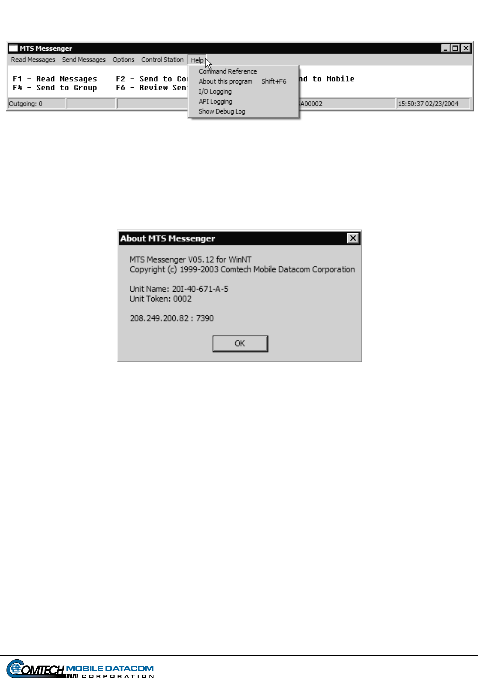
Contract No. DAAB15-99-D-0014 MTS Users Manual Revision: 1.9.1a
Page 7-18
7.2 The Help Menu
Figure 7-34 The Help Menu
7.2.1 Help About this program
To determine the MTS version loaded on your computer, select Help from the MTS
Messenger menu. Select About this program (see Figure 7-35).
Figure 7-35 About MTS Messenger
7.2.2 Help, Other menu options.
Other help menu options are System Administrator tasks and are described in section
9.
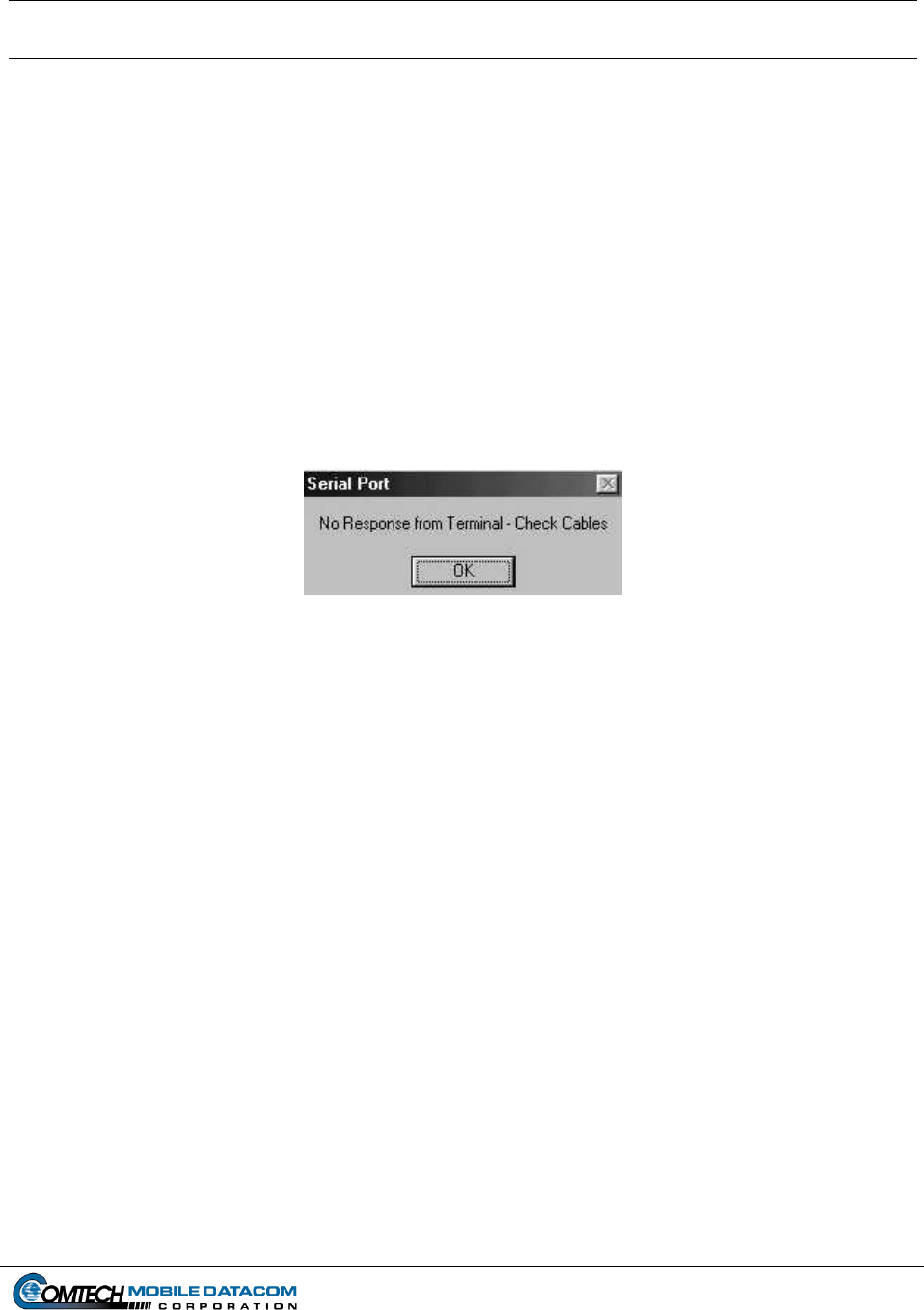
Contract No. DAAB15-99-D-0014 MTS Users Manual Revision: 1.9.1a
Page 8-1
8. Troubleshooting
8.1 Control Station
8.1.1 Can’t logon to windows
Be sure that you have correctly typed your username and password. Passwords are
case sensitive, so ensure that the Caps Lock key is not depressed. If you are still
unable to log on, contact your Control Station Operator or the unit CSSAMO. If they
are not able to resolve the issue, they will contact the Comtech Mobile Datacom
Support Center.
8.2 Control Station and V2
8.2.1 Error message when starting MTS Messenger
Figure 8-1 No Response from Terminal Error Message
(1) Close MTS Messenger.
(2) Restart MTS Messenger. When starting MTS messenger, be sure that the correct
COM port has been selected. If you select the incorrect COM port MTS
Messenger will not start. Power down the transceiver, and power it back up (per
the instructions in this manual).
Control Station configurations should use COM3
V2 configurations refer to Errata Sheet for COM port configuration.
If you still see the error message in Figure 8-1, go to step 3.
(3) Restart MTS Messenger (per the instructions in this manual). If you still see the
error message in Figure 8-1, contact your Control Station Operator or the unit
CSSAMO. If they are not able to resolve the issue, they will contact the Comtech
Mobile Datacom Support Center.

Contract No. DAAB15-99-D-0014 MTS Users Manual Revision: 1.9.1a
Page 8-2
8.3 Call Support
Should you encounter other problems please contact your Control Station Operator,
System Administrator, or the unit CSSAMO. If they are not able to resolve the issue,
they will contact the Comtech Mobile Datacom Support Center.