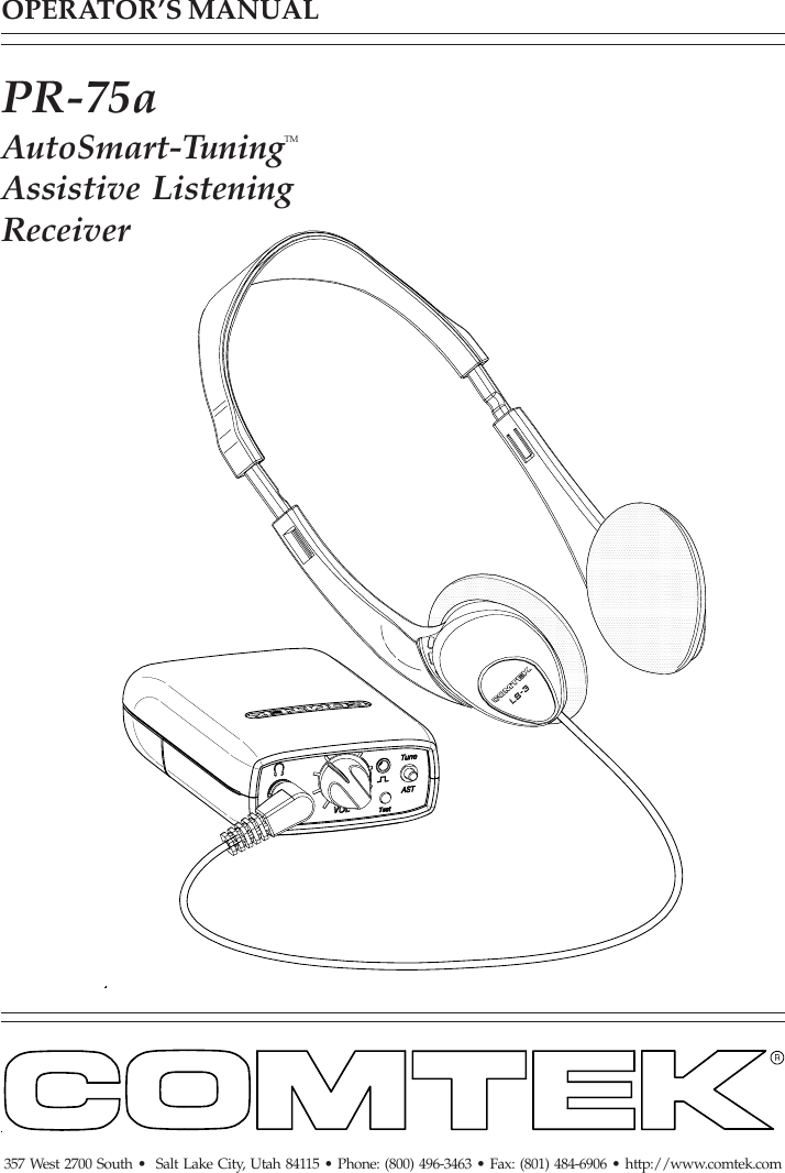
Comtek Communications Technology PR75A Scanning Receiver in upper 72 MHz to 76 MHz range. User Manual pr75Amanualsingle

Comtek Communications Technology Inc Scanning Receiver in upper 72 MHz to 76 MHz range. pr75Amanualsingle

Users Manual

OPERATOR’S MANUAL357 West 2700 South •  Salt Lake City, Utah 84115 • Phone: (800) 496-3463 • Fax: (801) 484-6906 • http://www.comtek.comPR-75aAutoSmart-TuningTMAssistive ListeningReceiver
TABLE OF CONTENTSIntroduction  ..........................................................Controls and Indicators  ..................................Setup and Operation   .....................................................Optional Accessories  ........................................Frequency Information  .....................................Battery Information  ...............................................Belt Clip Installation and Removal  ........................Specifications  ....................................................Warranty and Service  .......................................© 2004 COMTEK® All rights reserved.Print Release Date 02-20-2004123-456-78-9101112WARNING:  MODIFICATION OF THIS DEVICETO RECEIVE CELLULAR RADIOTELEPHONESERVICE SIGNALS IS PROHIBITED UNDERFCC RULES AND FEDERAL LAW.
INTRODUCTIONPage 1The PR-75a personal receiver isthe newest generation of user-friendly,high fidelity monitor receivers forauditory assistance and other personalcommunication applications.  Whenturned on, this unique receiver willautomatically tune itself to the closesttransmitter.  If other transmissionsneed to be monitored, a manual,AutoSmart-TuningTM (AST) controlwill cause the receiver to seek anyon-channel group frequencytransmission in the 72-76 MHz band.PR-75aAutoSmart-TuningTMAssistive ListeningReceiver
PR-75a CONTROLS AND INDICATORSPage 2PR-75a Controls! BATTERY COMPARTMENT:The battery compartmentfeatures a hinged battery coverand a polarity protection designto ensure that only properbattery polarity can occur." AUDIO OUTPUT JACK:This stereo/mono audiooutput jack accommodatesany low impedance headphone;also functions as automatic on/offpower switch when headphone isplugged in and as rechargeable batterycharging access.# VOLUME CONTROL:This control has 50 dB of range to adjust the audiooutput for a comfortable listening level(clockwise for maximum level).$ POWER / RECEIVER STATUS INDICATOR:LED indicator will display these four functions:a.  Fast blinking ----- Seeking channelb.  Continuous ------- Receiving signalc.  Steady slow flash -------- No signald.  Rapid flash ------ Low battery      Additionally there is an audible      beeping to indicate a low battery.% AutoSmart-TuningTM  PUSH BUTTON:This one-button tuning control (AST)allows the receiver to seek other channelswithin the frequency group to which it is tuned.&  DATA I/O PORT:For channel programming of specialty channel sequencing.
Setupa.  Open the battery door on the receiver (see page 8) and insert two 1.5 V AAalkaline batteries (Eveready E91 or equivalent).  This type of battery will offerup to 100 hours of operation.  If a rechargeable battery is to be used, ensurethat it has been allowed to charge at least twelve hours to bring it to fullcharge  (see page 9 for battery charger instructions).  Replace the battery beforeevery use if the demand for fail-safe operation outweighs battery cost.  The use ofcarbon batteries is not recommended.b.  Ensure that there is a signal on the air on a channel from A-J(see frequency chart page 6).  The PR-75a receiver must be within 150 feetof the transmitter for best reception.c.  Plugging the earphone into the “Auto-On” output jack on the top of thePR-75a receiver will automatically turn on the receiver and initiate theAutoSmart-TuningTM  process.  (The LED will blink very rapidly during thisprocess.)  The receiver will then tune itself to the closest on-air transmitter inits vicinity.  Based on the first channel found, the receiver will then determinethe channel group to which it belongs for multiple channel operation.(The LED will illuminate continuously when a signal is being received.)Pushing the  AutoSmart-TuningTM  button (AST) will cause the receiver toseek another compatible channel being transmitted in the frequency groupbeing used.NOTE:  The headphone cord also functions as part of the receiver’santenna system.  For optimum performance, this cord should be fullyextended.  Coiling or bunching the headphone cord may reduce the rangeof the receiver.  Also, coil-cord type headphone cords are notrecommended.  The receiver should be carried by the snap-on belt clip(included) or in a pocket or belt-clip pouch.d.  Set the audio output level control to a comfortable listening volume.  Thiscontrol is turned clockwise for maximum output level.PR-75a SETUP AND OPERATIONPage 3
Page 4PR-75a SETUP AND OPERATIONMonitoring CapabilitiesBecause each monitoring application requires a differentheadphone or transducer to best satisfy each listeningneed, the PR-75a can source a strong audio signal(200 mW) to either stereo or mono headphoneswith an impedance as low as 16 ohm.A hearing aid type button receiver maybe used with an impedance as high as2k ohm and still produce a strongaudio signal.The PR-75a is ideal for use with theCOMTEK  NTC-102 necklooptransductor and wireless IR-230miniature universal-fit ear canalinductor receiver or with hearingaids having a “T” switch.Can be used with consumer orprofessional headphones.Can be used withhearing aid buttonreceivers for assistivelistening or acousticear tube for IFBapplication. Can be used todrive neckloop foruse with IR-230inductor receiver orhearing  aids.
Page 5PR-75a OPTIONAL  ACCESSORIESOptional Accessories1.    NBC 3-1   3 volt 12 hour battery charger2.    NH 1600   Rechargeable  Ni-MH battery       (1.2 volt 1600 mAh)3.    P-1   Universal pouch4.    BC-216   Snap-on belt clip       (supplied with PR-75a)5.    ET-4 SM-N   Button receiver with acoustic ear tube6.    LS-3   High efficiency headphones7.    SM-N   Button receiver earphone assembly8.    NTC-102   Neckloop transductor       (for use with hearing aids or IR230)9.    NBC 9-3-12   Digital 12 station fast charger10.  FP-75   Channel programmer
PR-75a FREQUENCY INFORMATIONPage 6CHANNEL FREQUENCYABCDEFGHIJ72.100 MHz72.300 MHz72.500 MHz72.700 MHz72.900 MHz75.500 MHz75.700 MHz75.900 MHz74.700 MHz75.300 MHz72 MHz WIDE-BANDCHANNELSCHANNEL FREQUENCYAEHJ72.100 MHz72.900 MHz75.900 MHz75.300 MHzGROUP FREQUENCYCHARTGROUP 1CHANNEL FREQUENCYBGI72.300 MHz75.700 MHz74.700 MHzCHANNEL FREQUENCYCF72.500 MHz75.500 MHzCustom ProgrammingThe Data I/O port allowscustom channel programmingwith the FP-75 programmer tocreate new dedicated frequencygroups.  These frequencies canthen operate in sequence for“roundabout” type channelselection with the AST pushbutton.  A dedicated singlechannel can also be programmed.GROUP FREQUENCYCHARTGROUP 2GROUP FREQUENCYCHARTGROUP 3
Page 7Multiple Channel OperationWhen multiple transmitters (more than two) are used in the same proximity,intermodulation interference often occurs.  This condition is common to allradio receivers to some extent when multiple transmitters are used in thesame operating area.  The RF signals will “MIX” together generatingadditional signals.  If these product frequencies are too close to a frequencywhich the receiver can also respond to, you will experience intermodulationinterference which may cause undesirable operation.To avoid this type of interference when multiple transmitters are used in thesame proximity, transmitting frequencies must be coordinated  by selectingfrom frequencies in the same group.  (See group frequency chart on page 6.)When programming new customized frequency groups with the FP-75channel programmer, COMTEK’s Frequency Selection Guide Software canbe used to determine appropriate frequencies.  Contact COMTEK to obtain afree copy of the frequency selection software or download it from COMTEK’sweb site at www.comtek.com/software.htmltransmitterstransmitterstransmittersGroup 1operating areaGroup 2operating area Group 3operating areaTransmitterseparationTransmitterseparationTransmitter ProximitiesFor Multiple ChannelOperationFrequency groups being transmittedshould be separated by 2Xthe operating area; and forbest performance, thegroup operating areasshould have a 100 ft.minimum separation.
PR-75a BATTERY INFORMATIONPage 8Low Battery IndicatorThe LED indicator on the PR-75a is a multi-function indicator whichincludes low battery detection.  When the receiver is operating normally,the LED indicator illuminates continuously indicating that the receiver isreceiving a signal on the tuned channel.  Ifthe battery is low, the LED will show asteady fast flash indicating the batteryis low.  Additionally, if the user ismonitoring, an audible beeping soundwill be heard warning that the batterywill be dead soon.  Replace a lowbattery immediately as performance ofthe receiver will be unpredictable andmay vary from audio distortion tocomplete failure to operate.Battery Removal / ReplacementBattery indicator LEDPull back battery door latch and allowbattery cover door to spring open.  Toremove batteries, simply manipulatethe negative (-) end of battery out ofthe compartment and remove.To insert batteries, manipulate thepositive (+) end into place with correctpolarity as shown.  Press batteries intocompartment and close battery door untilit snaps shut.  Note:  Battery polaritymust be correct for unit to operate.
IMPORTANTPage 9Battery Charging1.  Make sure that two AA size 1.2 volt Ni-MH rechargeable      cells are used with a minimum of 1400 mAh capacity.      (Alkaline batteries must not be charged.)2.  Note that the red charging indicator on the charger is “ON” when the      PR-75a is plugged into the charger through the audio output jack.3.  When using the NBC -3 charger allow the battery to charge for 12 hours      for a full charge.  The unit must then be unplugged.  When using the      NBC 9-3-12 digital fast charger, the charger will automatically end the      charge cycle and the red LED will change to green.  With this charger,      the unit may be left in the charger until the unit is used.4.  Periodically open the battery compartment on stored COMTEK units to     check for battery leakage.  If a battery is leaking, it must be discarded,      and the battery compartment must be cleaned or returned to COMTEK’s      service department for repairs.NBC-3NBC 9-3-12
Belt clip installationPR-75a SNAP-ON BELT CLIPPage 10Belt clip removalHook belt clipretaining lip overfront case ridge.Rotate belt clip down onto case.Apply pressure on both sidesof clip, snapping clip retainersinto slots.Clip retainerRetainer slotBelt clip removal indentFlex out and pull down withyour thumb or a large coin(quarter) to unsnap belt clipfrom case.STEP 2:STEP 1:
PR-75a SPECIFICATIONSPage 11Audio Output:Headset output 200 mW average(Impedance as low as 16 ohm)Connectors:Stereo/mono 3.5 mm audio outputconnector and charging input.2.5 mm stereo connector for I/Odata programming.Indicators:Multi-function LEDa. Channel-seekingb. Received signalc.  No signald. Low batteryControls:Volume control (50 dB range)Automatic turn-on when headphoneis plugged in and turn-off whenheadphone is removed.One-button tuning control (AST)Audio Frequency Response:100 Hz to 10 kHz ±3 dBHarmonic Distortion:Less than 1% (1kHz tone 30 kHzdeviation)Operating Radio Frequency:72 to 76 MHzFrequency synthesized 10-channel,AutoSmart-TuningTM (AST)•••••Frequency Stability:0.002% frequency synthesizedcrystal controlledRF Sensitivity:2 µV for 38 dB of quieting(average)Ultimate Quieting:Better than 75 dB relatedto outputDeviation Acceptance:Up to ±75 kHzAntenna:Integral with headphone cable(no external antenna)Battery Life:100 hours with alkaline batteriesPower Requirements:2 AA 1.5 volt alkaline batteriesor rechargeable Ni-MH(NH 1600)FCC Compliance:Complies with Part 15of FCC rulesDimensions:1 1/16" x 2 1/2" x 3 1/4" (27 mm x 57 mm x 83 mm)NOTE:  Specifications subject to              change without notice••
357 West 2700 South • Salt Lake City, Utah  84115Phone: (800) 496-3463 • Fax: (801) 484-6906Web Page:  http://www.comtek.comPR-75a WARRANTY AND SERVICEWarrantyCOMTEK warrants this product to be free from defects in workmanship andmaterial under normal use and conditions for a period of one year from dateof original purchase. Items such as batteries, neckloops, and cords are notcovered by the warranty. Damage due to misuse, ill treatment andunauthorized modification and repairs are not covered by this warranty.  COMTEK isnot liable for consequential damages arising out of any failureof the equipment to perform as intended. COMTEK shall bear no responsibility orobligation with respect to the manner of use of any equipment sold by it.COMTEK SPECIFICALLY DISCLAIMS AND NEGATES ANY WARRANTY OFMERCHANTABILITY OR FITNESS FOR A PARTICULAR PURPOSEOF SUCH EQUIPMENT INCLUDING, WITHOUT LIMITATION, ANYWARRANTY THAT THE USE OF SUCH EQUIPMENT FOR ANY PURPOSEWILL COMPLY WITH APPLICABLE LAWS AND REGULATIONS.Service PoliciesWarranty repairs must be done by COMTEK.  Only factory technicians areauthorized to perform warranty service on the PR-75a receiver. Beforereturning the PR-75a for service, a Return Authorization Number shouldbe obtained from the service department by calling 1-800-496-3463 or1-801-466-3463. Return the unit to the factory with the original or comparablepacking.  COMTEK will pay for insurance and ground return shipping costs inthe United States for all warranty service.Page 12© 2004 COMTEK® All rights reserved.
357 West 2700 South •  Salt Lake City, Utah 84115 • Phone: (800) 496-3463 • Fax: (801) 484-6906 • http://www.comtek.com

Navigation menu