Comtek Communications Technology PR75A Scanning Receiver in upper 72 MHz to 76 MHz range. User Manual pr75Amanualsingle
Comtek Communications Technology Inc Scanning Receiver in upper 72 MHz to 76 MHz range. pr75Amanualsingle
Users Manual
OPERATOR’S MANUAL
357 West 2700 South • Salt Lake City, Utah 84115 • Phone: (800) 496-3463 • Fax: (801) 484-6906 • http://www.comtek.com
PR-75a
AutoSmart-TuningTM
Assistive Listening
Receiver

TABLE OF CONTENTS
Introduction ..........................................................
Controls and Indicators ..................................
Setup and Operation .....................................................
Optional Accessories ........................................
Frequency Information .....................................
Battery Information ...............................................
Belt Clip Installation and Removal ........................
Specifications ....................................................
Warranty and Service .......................................
© 2004 COMTEK® All rights reserved.
Print Release Date 02-20-2004
1
2
3-4
5
6-7
8-9
10
11
12
WARNING: MODIFICATION OF THIS DEVICE
TO RECEIVE CELLULAR RADIOTELEPHONE
SERVICE SIGNALS IS PROHIBITED UNDER
FCC RULES AND FEDERAL LAW.
INTRODUCTION
Page 1
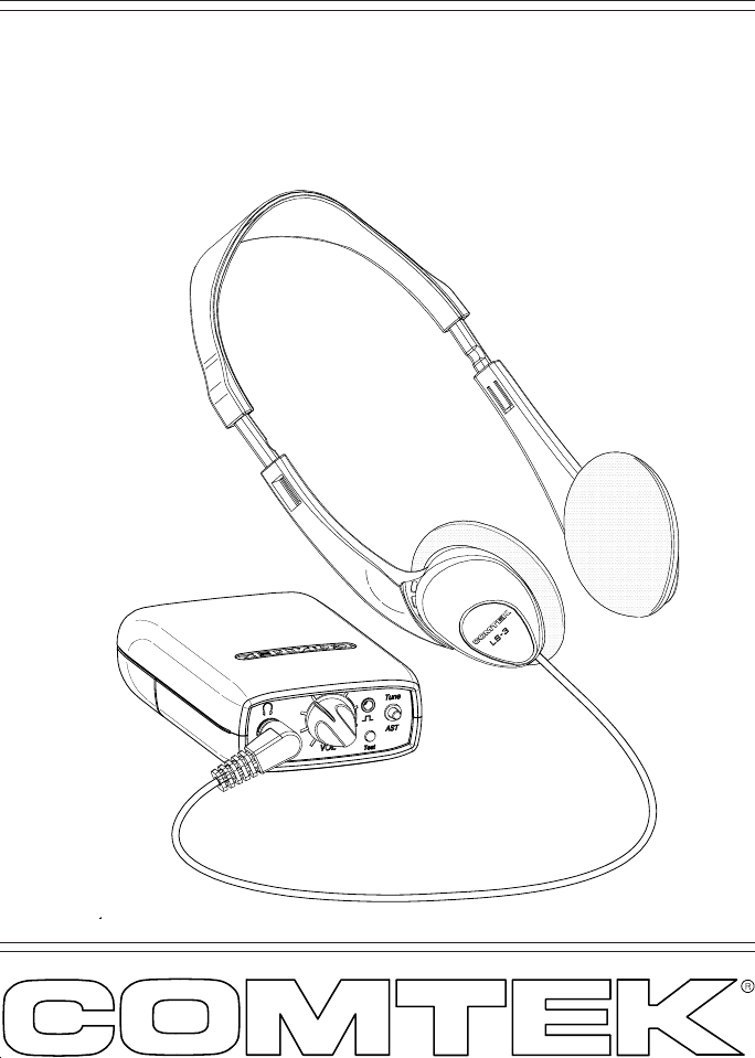
The PR-75a personal receiver is
the newest generation of user-friendly,
high fidelity monitor receivers for
auditory assistance and other personal
communication applications. When
turned on, this unique receiver will
automatically tune itself to the closest
transmitter. If other transmissions
need to be monitored, a manual,
AutoSmart-TuningTM (AST) control
will cause the receiver to seek any
on-channel group frequency
transmission in the 72-76 MHz band.
PR-75a
AutoSmart-TuningTM
Assistive Listening
Receiver
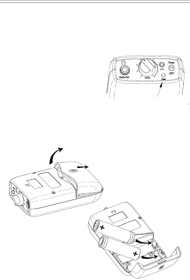
PR-75a CONTROLS AND INDICATORS
Page 2
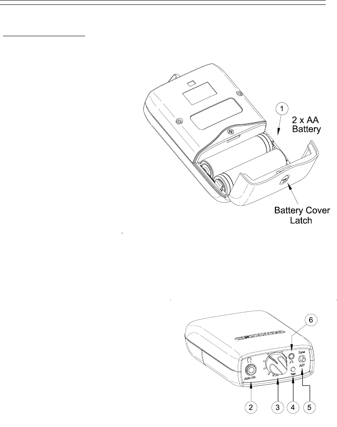
PR-75a Controls
! BATTERY COMPARTMENT:
The battery compartment
features a hinged battery cover
and a polarity protection design
to ensure that only proper
battery polarity can occur.
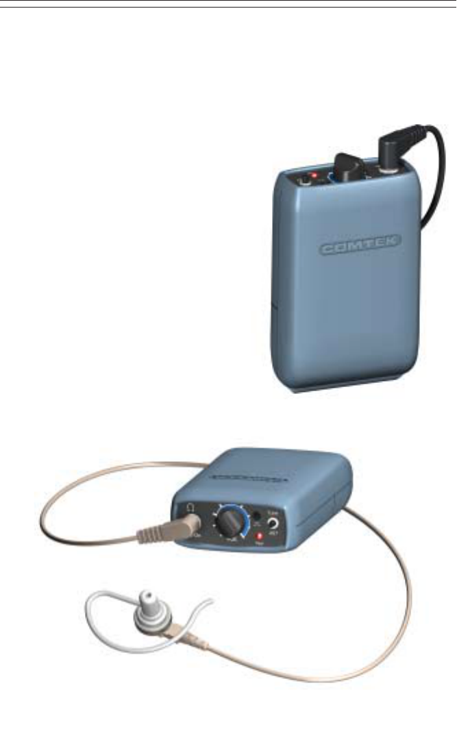
" AUDIO OUTPUT JACK:
This stereo/mono audio
output jack accommodates
any low impedance headphone;
also functions as automatic on/off
power switch when headphone is
plugged in and as rechargeable battery
charging access.
# VOLUME CONTROL:
This control has 50 dB of range to adjust the audio
output for a comfortable listening level
(clockwise for maximum level).
$ POWER / RECEIVER STATUS INDICATOR:
LED indicator will display these four functions:
a. Fast blinking ----- Seeking channel
b. Continuous ------- Receiving signal
c. Steady slow flash -------- No signal
d. Rapid flash ------ Low battery
Additionally there is an audible
beeping to indicate a low battery.
% AutoSmart-TuningTM PUSH BUTTON:
This one-button tuning control (AST)
allows the receiver to seek other channels
within the frequency group to which it is tuned.
& DATA I/O PORT:
For channel programming of specialty channel sequencing.

Setup
a. Open the battery door on the receiver (see page 8) and insert two 1.5 V AA
alkaline batteries (Eveready E91 or equivalent). This type of battery will offer
up to 100 hours of operation. If a rechargeable battery is to be used, ensure
that it has been allowed to charge at least twelve hours to bring it to full
charge (see page 9 for battery charger instructions). Replace the battery before
every use if the demand for fail-safe operation outweighs battery cost. The use of
carbon batteries is not recommended.
b. Ensure that there is a signal on the air on a channel from A-J
(see frequency chart page 6). The PR-75a receiver must be within 150 feet
of the transmitter for best reception.
c. Plugging the earphone into the “Auto-On” output jack on the top of the
PR-75a receiver will automatically turn on the receiver and initiate the
AutoSmart-TuningTM process. (The LED will blink very rapidly during this
process.) The receiver will then tune itself to the closest on-air transmitter in
its vicinity. Based on the first channel found, the receiver will then determine
the channel group to which it belongs for multiple channel operation.
(The LED will illuminate continuously when a signal is being received.)
Pushing the AutoSmart-TuningTM button (AST) will cause the receiver to
seek another compatible channel being transmitted in the frequency group
being used.
NOTE: The headphone cord also functions as part of the receiver’s
antenna system. For optimum performance, this cord should be fully
extended. Coiling or bunching the headphone cord may reduce the range
of the receiver. Also, coil-cord type headphone cords are not
recommended. The receiver should be carried by the snap-on belt clip
(included) or in a pocket or belt-clip pouch.
d. Set the audio output level control to a comfortable listening volume. This
control is turned clockwise for maximum output level.
PR-75a SETUP AND OPERATION
Page 3
Page 4
PR-75a SETUP AND OPERATION
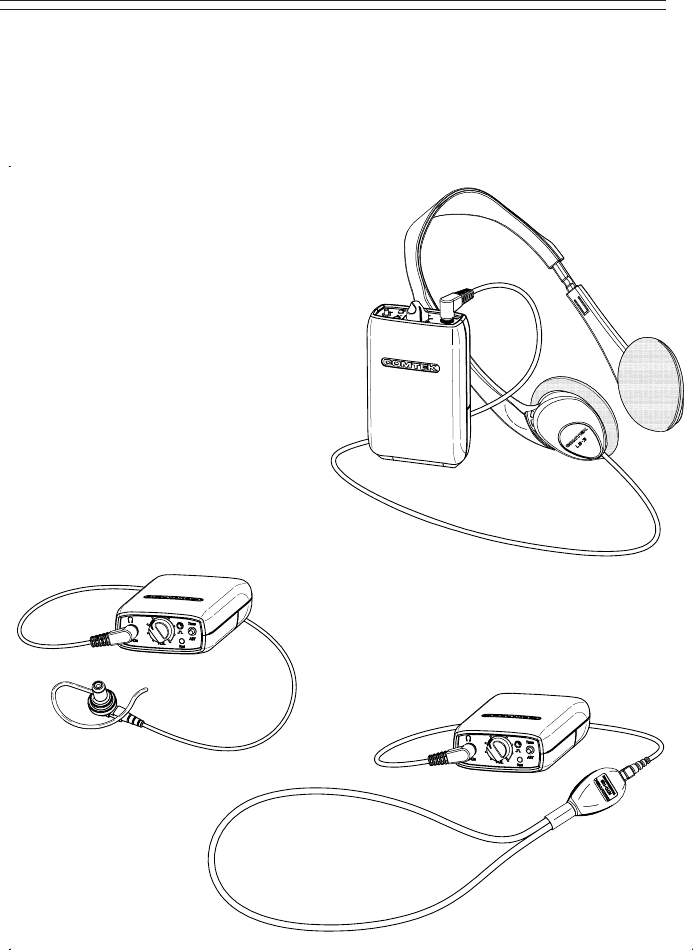
Monitoring Capabilities
Because each monitoring application requires a different
headphone or transducer to best satisfy each listening
need, the PR-75a can source a strong audio signal
(200 mW) to either stereo or mono headphones
with an impedance as low as 16 ohm.
A hearing aid type button receiver may
be used with an impedance as high as
2k ohm and still produce a strong
audio signal.
The PR-75a is ideal for use with the
COMTEK NTC-102 neckloop
transductor and wireless IR-230
miniature universal-fit ear canal
inductor receiver or with hearing
aids having a “T” switch.
Can be used with consumer or
professional headphones.
Can be used with
hearing aid button
receivers for assistive
listening or acoustic
ear tube for IFB
application. Can be used to
drive neckloop for
use with IR-230
inductor receiver or
hearing aids.
Page 5
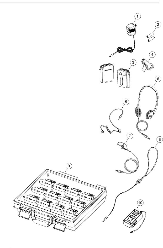
PR-75a OPTIONAL ACCESSORIES
Optional Accessories
1. NBC 3-1 3 volt 12 hour battery charger
2. NH 1600 Rechargeable Ni-MH battery
(1.2 volt 1600 mAh)
3. P-1 Universal pouch
4. BC-216 Snap-on belt clip
(supplied with PR-75a)
5. ET-4 SM-N Button receiver with acoustic ear tube
6. LS-3 High efficiency headphones
7. SM-N Button receiver earphone assembly
8. NTC-102 Neckloop transductor
(for use with hearing aids or IR230)
9. NBC 9-3-12 Digital 12 station fast charger
10. FP-75 Channel programmer
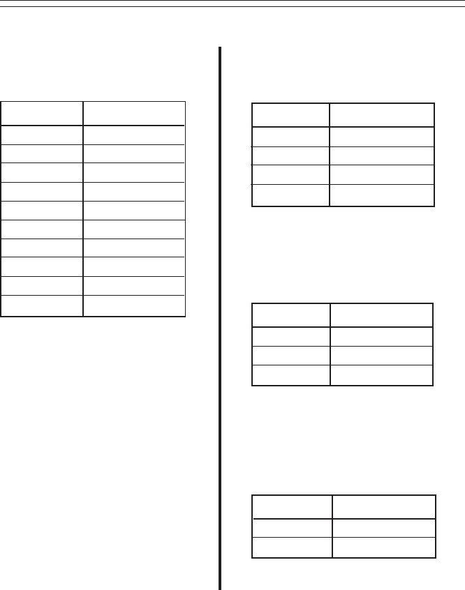
PR-75a FREQUENCY INFORMATION
Page 6
CHANNEL FREQUENCY
A
B
C
D
E
F
G
H
I
J
72.100 MHz
72.300 MHz
72.500 MHz
72.700 MHz
72.900 MHz
75.500 MHz
75.700 MHz
75.900 MHz
74.700 MHz
75.300 MHz
72 MHz WIDE-BAND
CHANNELS
CHANNEL FREQUENCY
A
E
H
J
72.100 MHz
72.900 MHz
75.900 MHz
75.300 MHz
GROUP FREQUENCY
CHART
GROUP 1
CHANNEL FREQUENCY
B
G
I
72.300 MHz
75.700 MHz
74.700 MHz
CHANNEL FREQUENCY
C
F72.500 MHz
75.500 MHz
Custom Programming
The Data I/O port allows
custom channel programming
with the FP-75 programmer to
create new dedicated frequency
groups. These frequencies can
then operate in sequence for
“roundabout” type channel
selection with the AST push
button. A dedicated single
channel can also be programmed.
GROUP FREQUENCY
CHART
GROUP 2
GROUP FREQUENCY
CHART
GROUP 3
Page 7
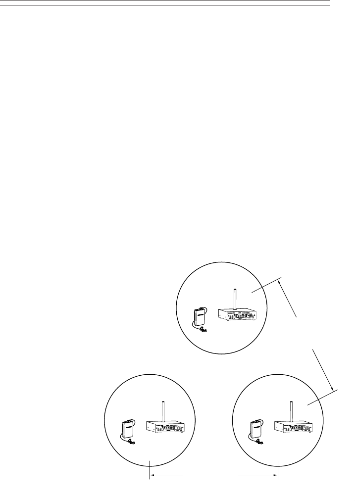
Multiple Channel Operation
When multiple transmitters (more than two) are used in the same proximity,
intermodulation interference often occurs. This condition is common to all
radio receivers to some extent when multiple transmitters are used in the
same operating area. The RF signals will “MIX” together generating
additional signals. If these product frequencies are too close to a frequency
which the receiver can also respond to, you will experience intermodulation
interference which may cause undesirable operation.
To avoid this type of interference when multiple transmitters are used in the
same proximity, transmitting frequencies must be coordinated by selecting
from frequencies in the same group. (See group frequency chart on page 6.)
When programming new customized frequency groups with the FP-75
channel programmer, COMTEK’s Frequency Selection Guide Software can
be used to determine appropriate frequencies. Contact COMTEK to obtain a
free copy of the frequency selection software or download it from COMTEK’s
web site at www.comtek.com/software.html
transmitterstransmitters
transmitters
Group 1
operating area
Group 2
operating area Group 3
operating area
Transmitter
separation
Transmitter
separation
Transmitter Proximities
For Multiple Channel
Operation
Frequency groups being transmitted
should be separated by 2X
the operating area; and for
best performance, the
group operating areas
should have a 100 ft.
minimum separation.
PR-75a BATTERY INFORMATION
Page 8
Low Battery Indicator
The LED indicator on the PR-75a is a multi-function indicator which
includes low battery detection. When the receiver is operating normally,
the LED indicator illuminates continuously indicating that the receiver is
receiving a signal on the tuned channel. If
the battery is low, the LED will show a
steady fast flash indicating the battery
is low. Additionally, if the user is
monitoring, an audible beeping sound
will be heard warning that the battery
will be dead soon. Replace a low
battery immediately as performance of
the receiver will be unpredictable and
may vary from audio distortion to
complete failure to operate.
Battery Removal / Replacement
Battery indicator LED
Pull back battery door latch and allow
battery cover door to spring open. To
remove batteries, simply manipulate
the negative (-) end of battery out of
the compartment and remove.
To insert batteries, manipulate the
positive (+) end into place with correct
polarity as shown. Press batteries into
compartment and close battery door until
it snaps shut. Note: Battery polarity
must be correct for unit to operate.
IMPORTANT
Page 9
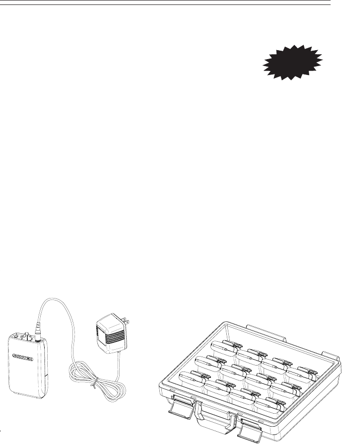
Battery Charging
1. Make sure that two AA size 1.2 volt Ni-MH rechargeable
cells are used with a minimum of 1400 mAh capacity.
(Alkaline batteries must not be charged.)
2. Note that the red charging indicator on the charger is “ON” when the
PR-75a is plugged into the charger through the audio output jack.
3. When using the NBC -3 charger allow the battery to charge for 12 hours
for a full charge. The unit must then be unplugged. When using the
NBC 9-3-12 digital fast charger, the charger will automatically end the
charge cycle and the red LED will change to green. With this charger,
the unit may be left in the charger until the unit is used.
4. Periodically open the battery compartment on stored COMTEK units to
check for battery leakage. If a battery is leaking, it must be discarded,
and the battery compartment must be cleaned or returned to COMTEK’s
service department for repairs.
NBC-3
NBC 9-3-12
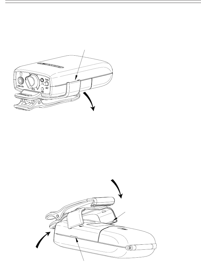
Belt clip installation
PR-75a SNAP-ON BELT CLIP
Page 10
Belt clip removal
Hook belt clip
retaining lip over
front case ridge.
Rotate belt clip down onto case.
Apply pressure on both sides
of clip, snapping clip retainers
into slots.
Clip retainer
Retainer slot
Belt clip removal indent
Flex out and pull down with
your thumb or a large coin
(quarter) to unsnap belt clip
from case.
STEP 2:
STEP 1:

PR-75a SPECIFICATIONS
Page 11
Audio Output:
Headset output 200 mW average
(Impedance as low as 16 ohm)
Connectors:
Stereo/mono 3.5 mm audio output
connector and charging input.
2.5 mm stereo connector for I/O
data programming.
Indicators:
Multi-function LED
a. Channel-seeking
b. Received signal
c. No signal
d. Low battery
Controls:
Volume control (50 dB range)
Automatic turn-on when headphone
is plugged in and turn-off when
headphone is removed.
One-button tuning control (AST)
Audio Frequency Response:
100 Hz to 10 kHz ±3 dB
Harmonic Distortion:
Less than 1% (1kHz tone 30 kHz
deviation)
Operating Radio Frequency:
72 to 76 MHz
Frequency synthesized 10-channel,
AutoSmart-TuningTM (AST)
•
•
•
•
•
Frequency Stability:
0.002% frequency synthesized
crystal controlled
RF Sensitivity:
2 µV for 38 dB of quieting
(average)
Ultimate Quieting:
Better than 75 dB related
to output
Deviation Acceptance:
Up to ±75 kHz
Antenna:
Integral with headphone cable
(no external antenna)
Battery Life:
100 hours with alkaline batteries
Power Requirements:
2 AA 1.5 volt alkaline batteries
or rechargeable Ni-MH
(NH 1600)
FCC Compliance:
Complies with Part 15
of FCC rules
Dimensions:
1 1
/16" x 2 1
/2" x 3 1
/4"
(27 mm x 57 mm x 83 mm)
NOTE: Specifications subject to
change without notice
•
•

357 West 2700 South • Salt Lake City, Utah 84115
Phone: (800) 496-3463 • Fax: (801) 484-6906
Web Page: http://www.comtek.com
PR-75a WARRANTY AND SERVICE
Warranty
COMTEK warrants this product to be free from defects in workmanship and
material under normal use and conditions for a period of one year from date
of original purchase. Items such as batteries, neckloops, and cords are not
covered by the warranty. Damage due to misuse, ill treatment and
unauthorized modification and repairs are not covered by this warranty. COMTEK is
not liable for consequential damages arising out of any failure
of the equipment to perform as intended. COMTEK shall bear no responsibility or
obligation with respect to the manner of use of any equipment sold by it.
COMTEK SPECIFICALLY DISCLAIMS AND NEGATES ANY WARRANTY OF
MERCHANTABILITY OR FITNESS FOR A PARTICULAR PURPOSE
OF SUCH EQUIPMENT INCLUDING, WITHOUT LIMITATION, ANY
WARRANTY THAT THE USE OF SUCH EQUIPMENT FOR ANY PURPOSE
WILL COMPLY WITH APPLICABLE LAWS AND REGULATIONS.
Service Policies
Warranty repairs must be done by COMTEK. Only factory technicians are
authorized to perform warranty service on the PR-75a receiver. Before
returning the PR-75a for service, a Return Authorization Number should
be obtained from the service department by calling 1-800-496-3463 or
1-801-466-3463. Return the unit to the factory with the original or comparable
packing. COMTEK will pay for insurance and ground return shipping costs in
the United States for all warranty service.
Page 12
© 2004 COMTEK® All rights reserved.

357 West 2700 South • Salt Lake City, Utah 84115 • Phone: (800) 496-3463 • Fax: (801) 484-6906 • http://www.comtek.com