Comtrend AR-5389 AR-5389 User Manual AR 5389 1
Comtrend Corporation AR-5389 AR 5389 1
UserManual.wiki
>
Comtrend
>
AR-5389 User Manual
>
AR-5389_user manual-1
Contents
1.
AR-5389_user manual-1
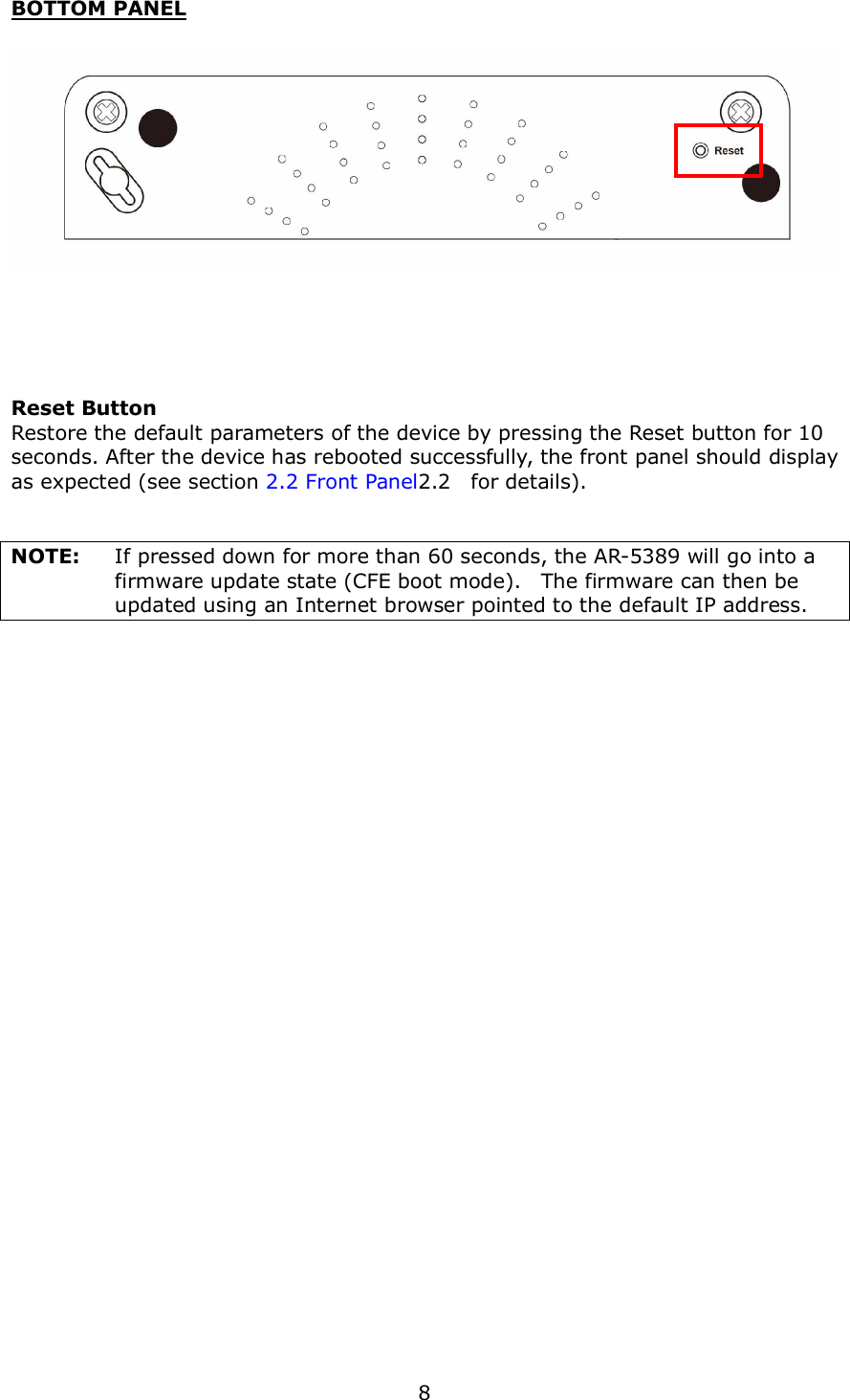
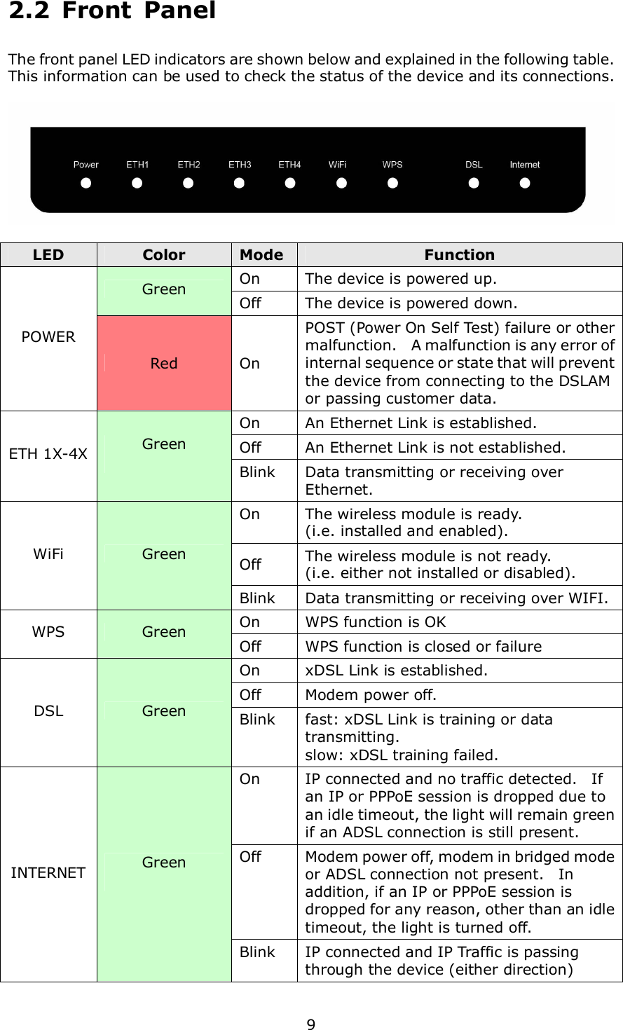
2.
AR-5389_user manual-2
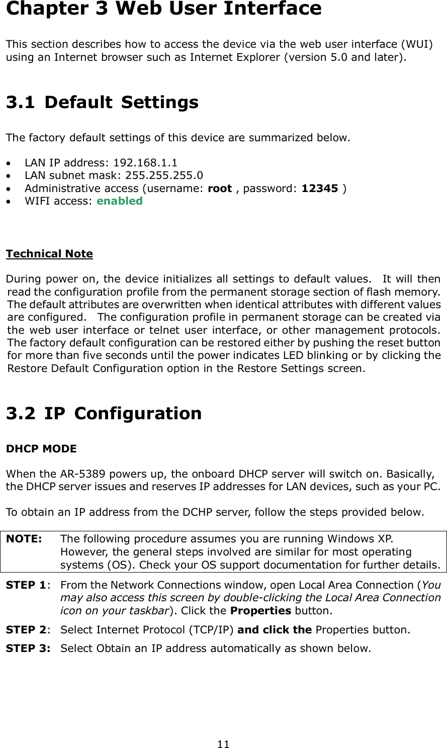
3.
AR-5389_user manual-3
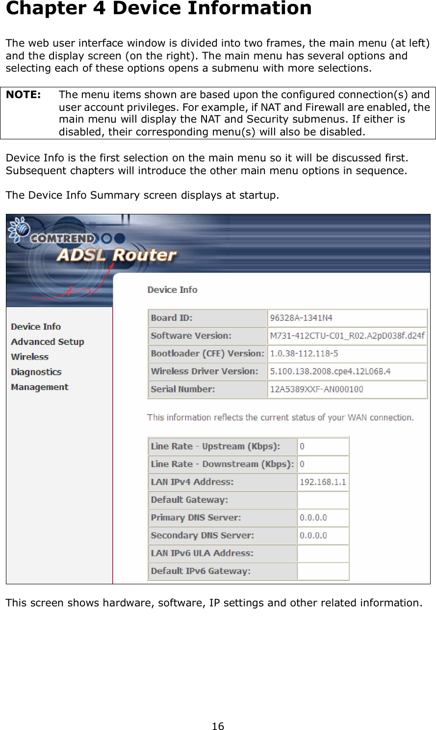
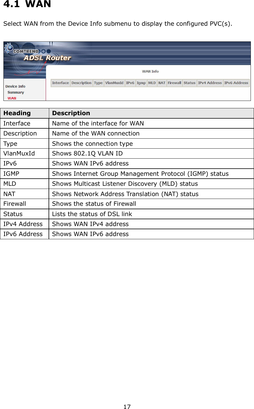
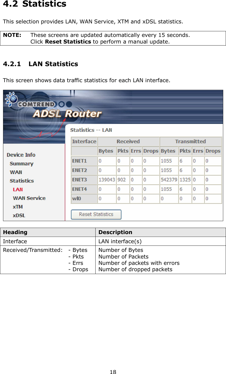
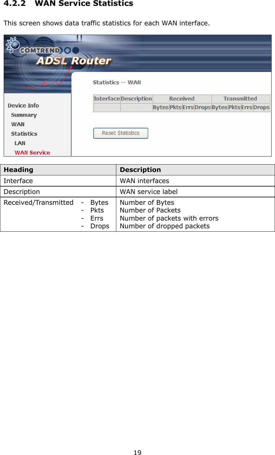
4.
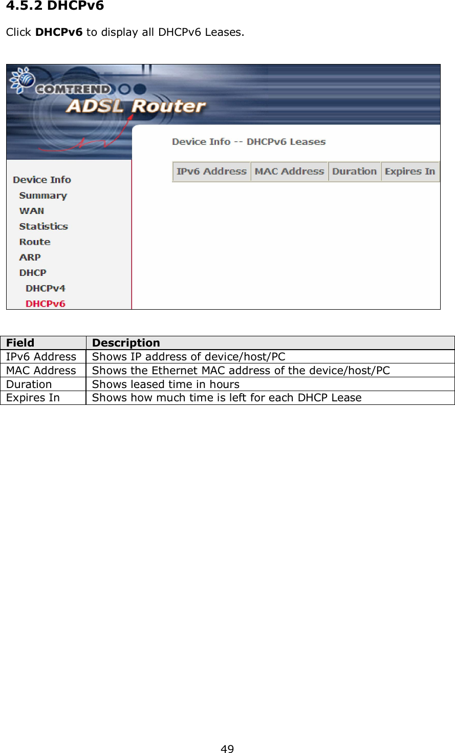
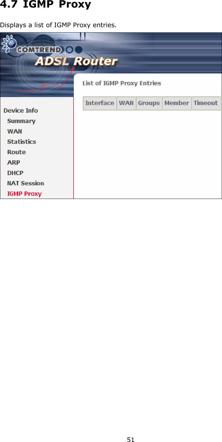
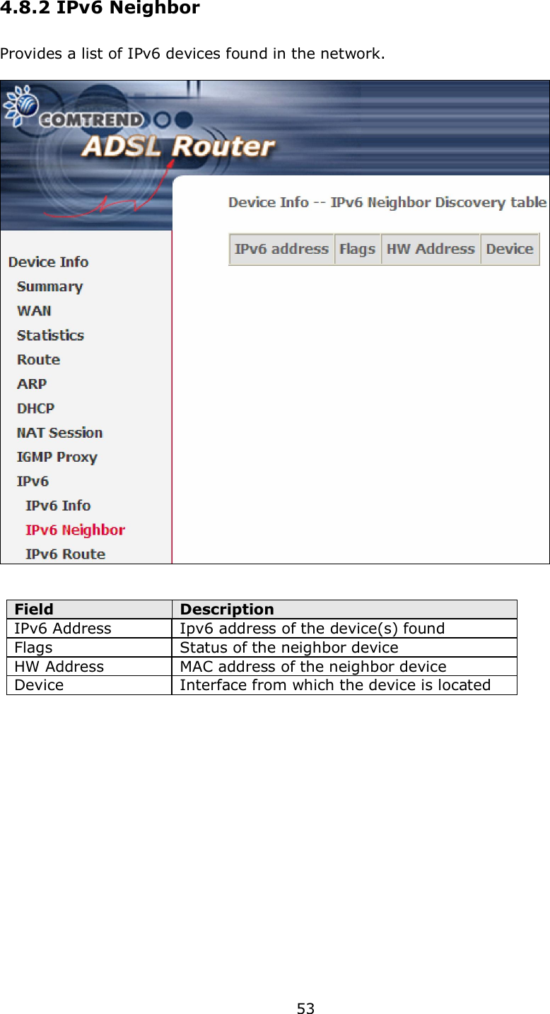
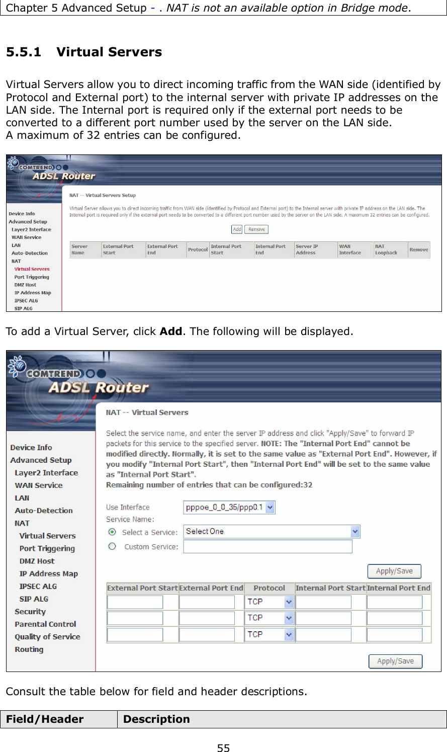
AR-5389_user manual-4
AR-5389_user manual-1
Navigation menu
Upload a User Manual
Namespaces
Wiki Guide
HTML
PDF
Info
Views
User Manual
Discussion / Help
Navigation