Comtrend AR-5389 AR-5389 User Manual AR 5389 3
Comtrend Corporation AR-5389 AR 5389 3
UserManual.wiki
>
Comtrend
>
AR-5389 User Manual
>
AR-5389_user manual-3
Contents
1.
AR-5389_user manual-1
2.
AR-5389_user manual-2
3.
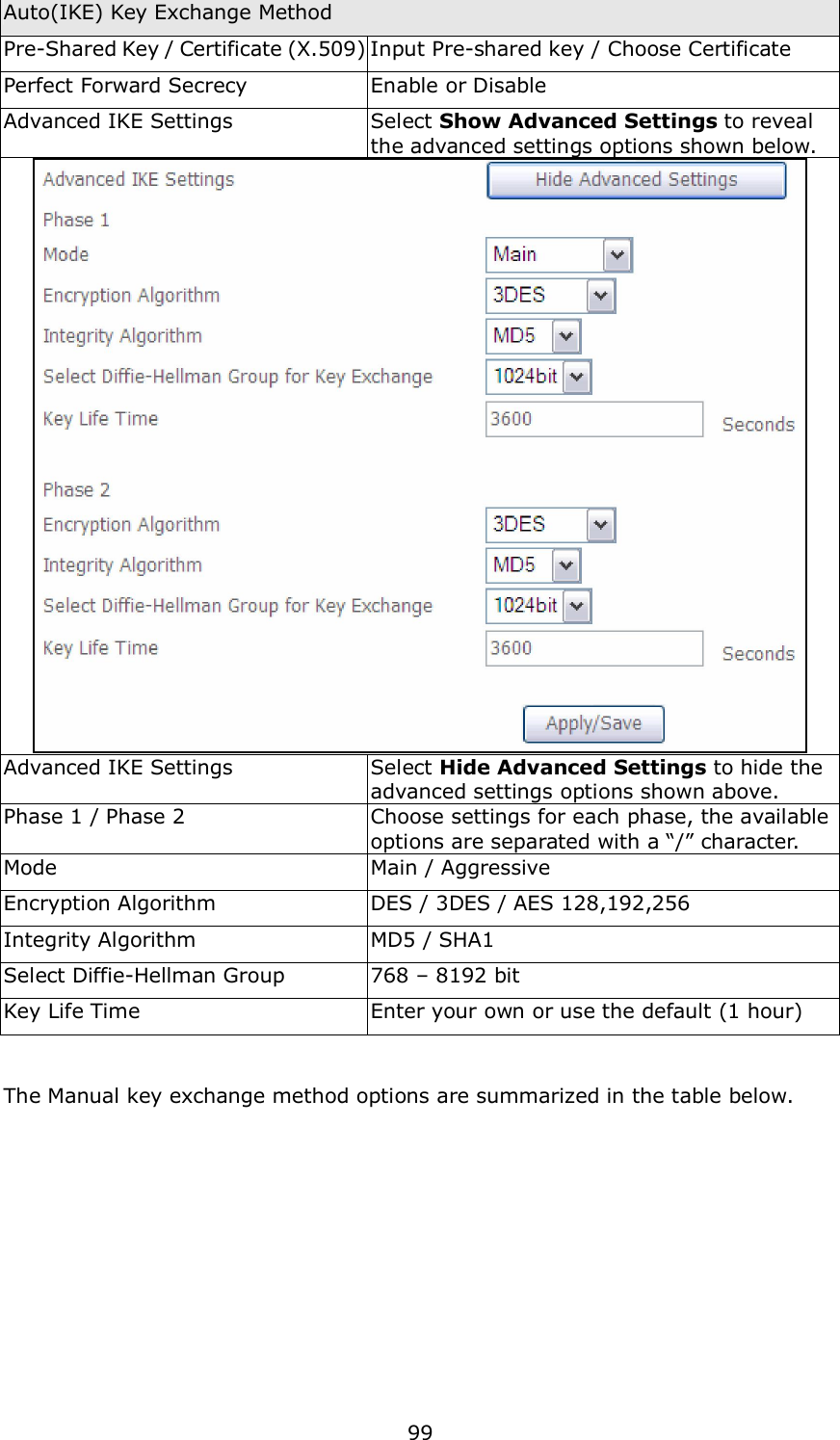
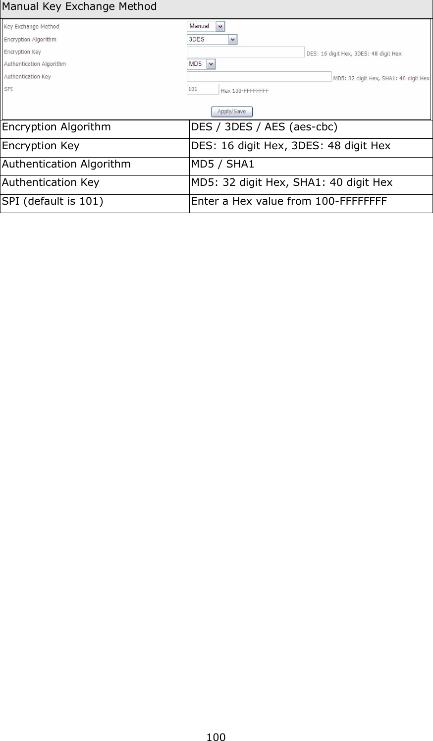
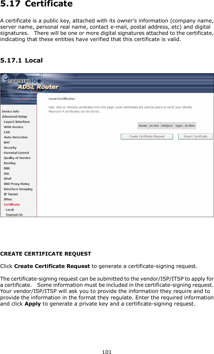
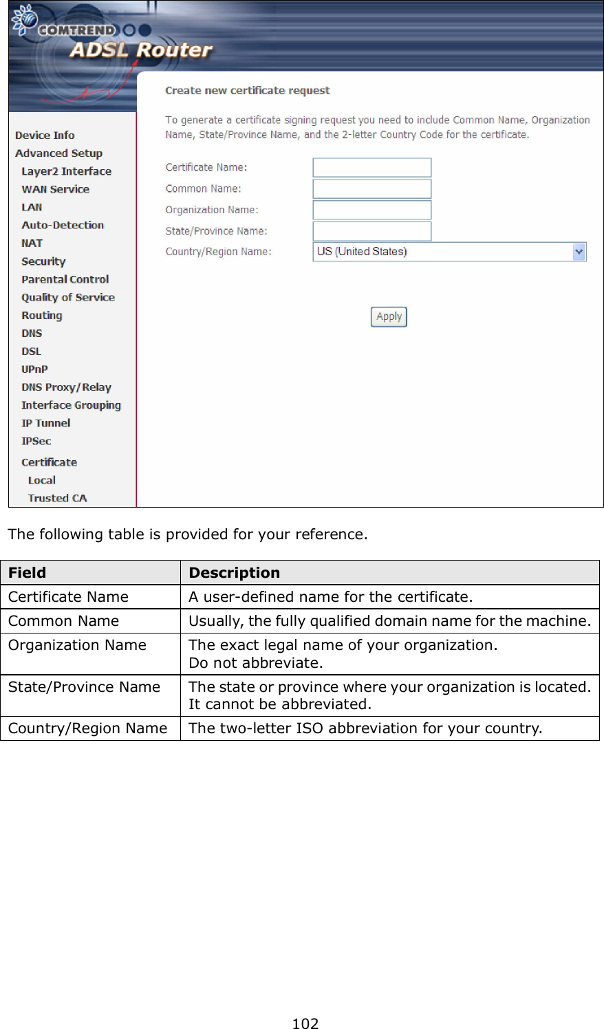
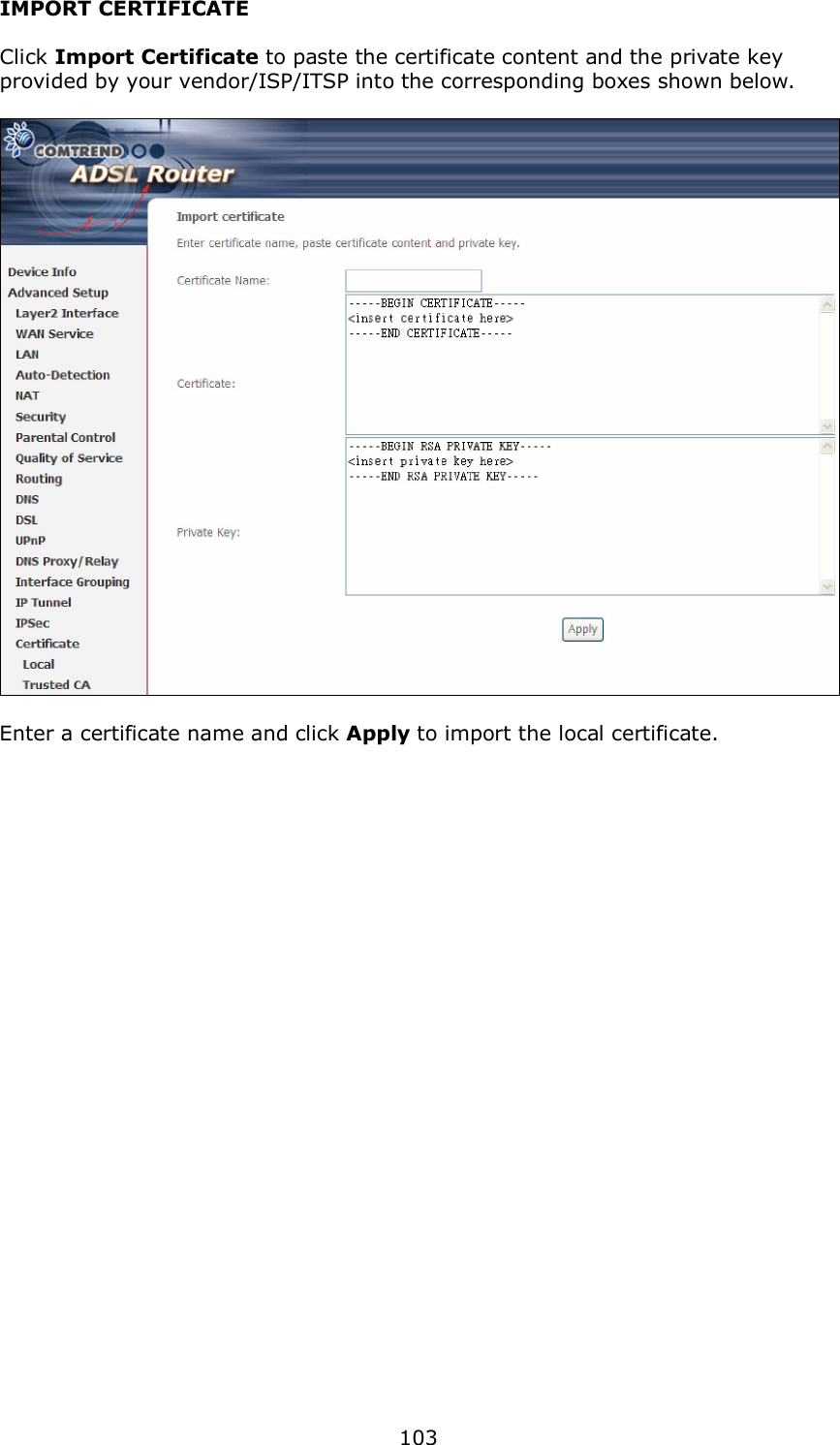
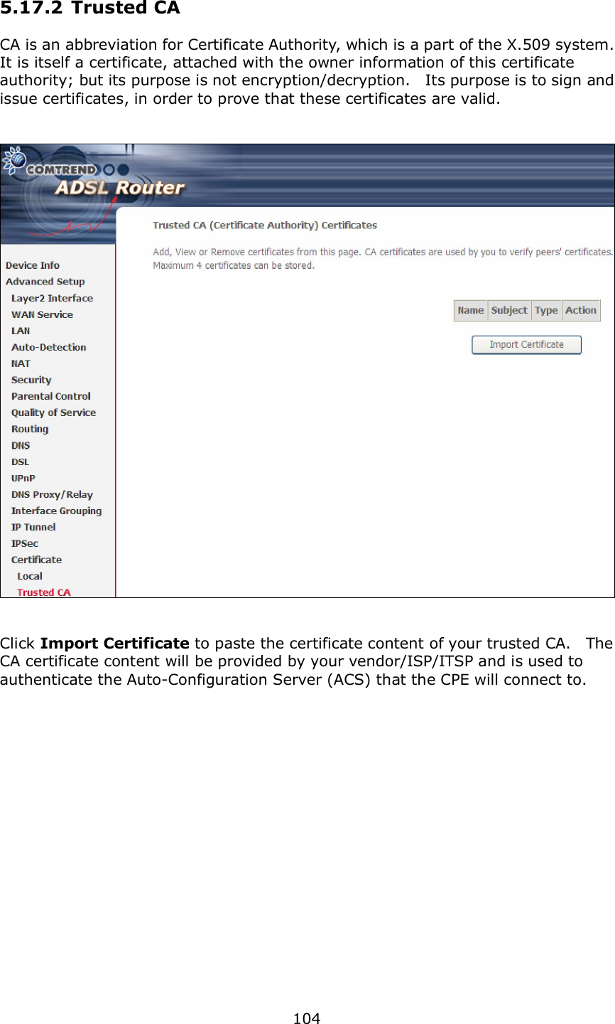
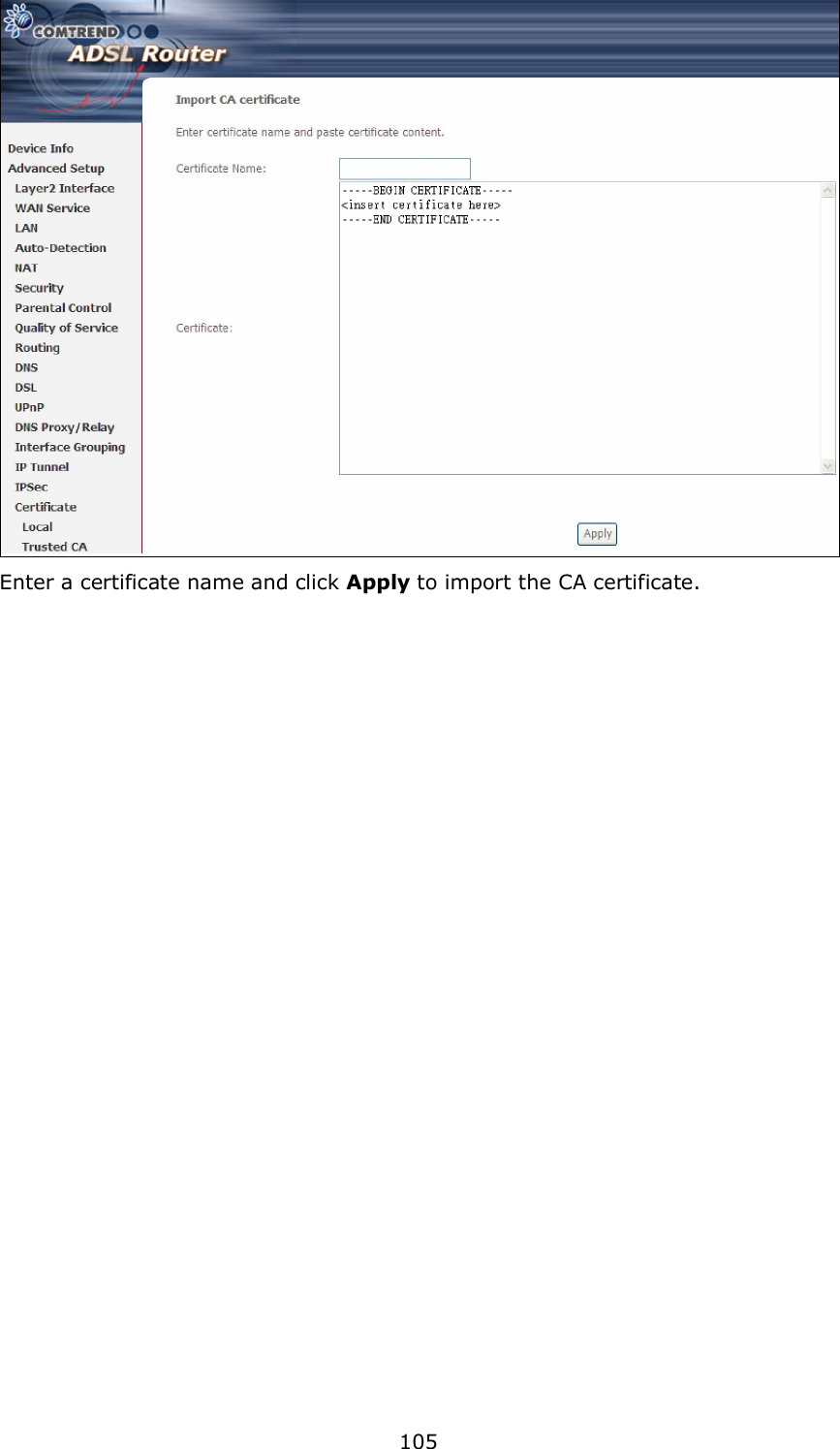
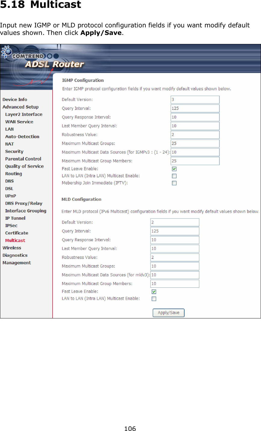
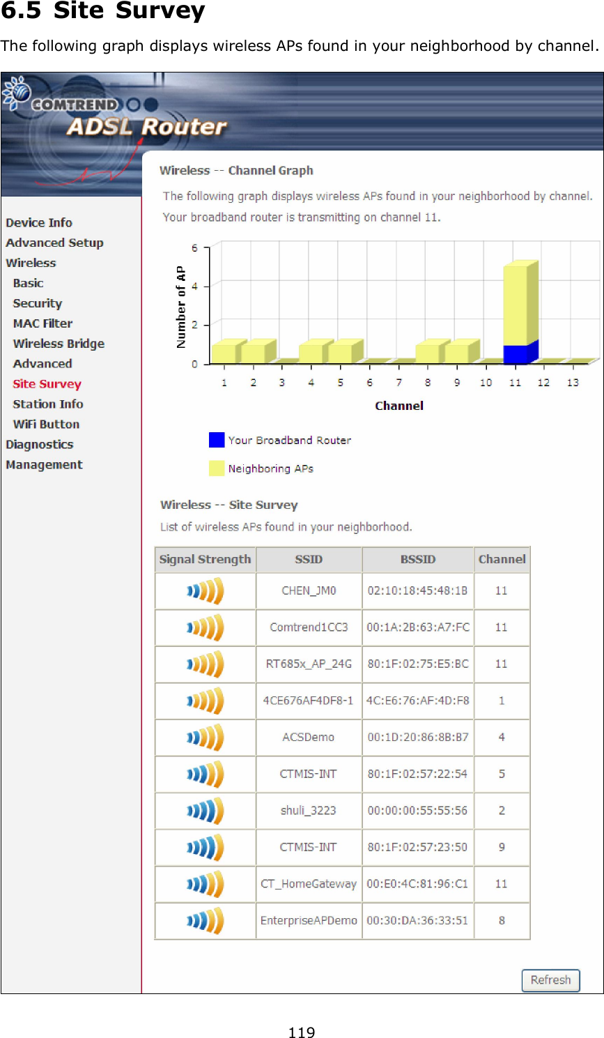
AR-5389_user manual-3
4.
AR-5389_user manual-4
AR-5389_user manual-3
Navigation menu
Upload a User Manual
Namespaces
Wiki Guide
HTML
PDF
Info
Views
User Manual
Discussion / Help
Navigation
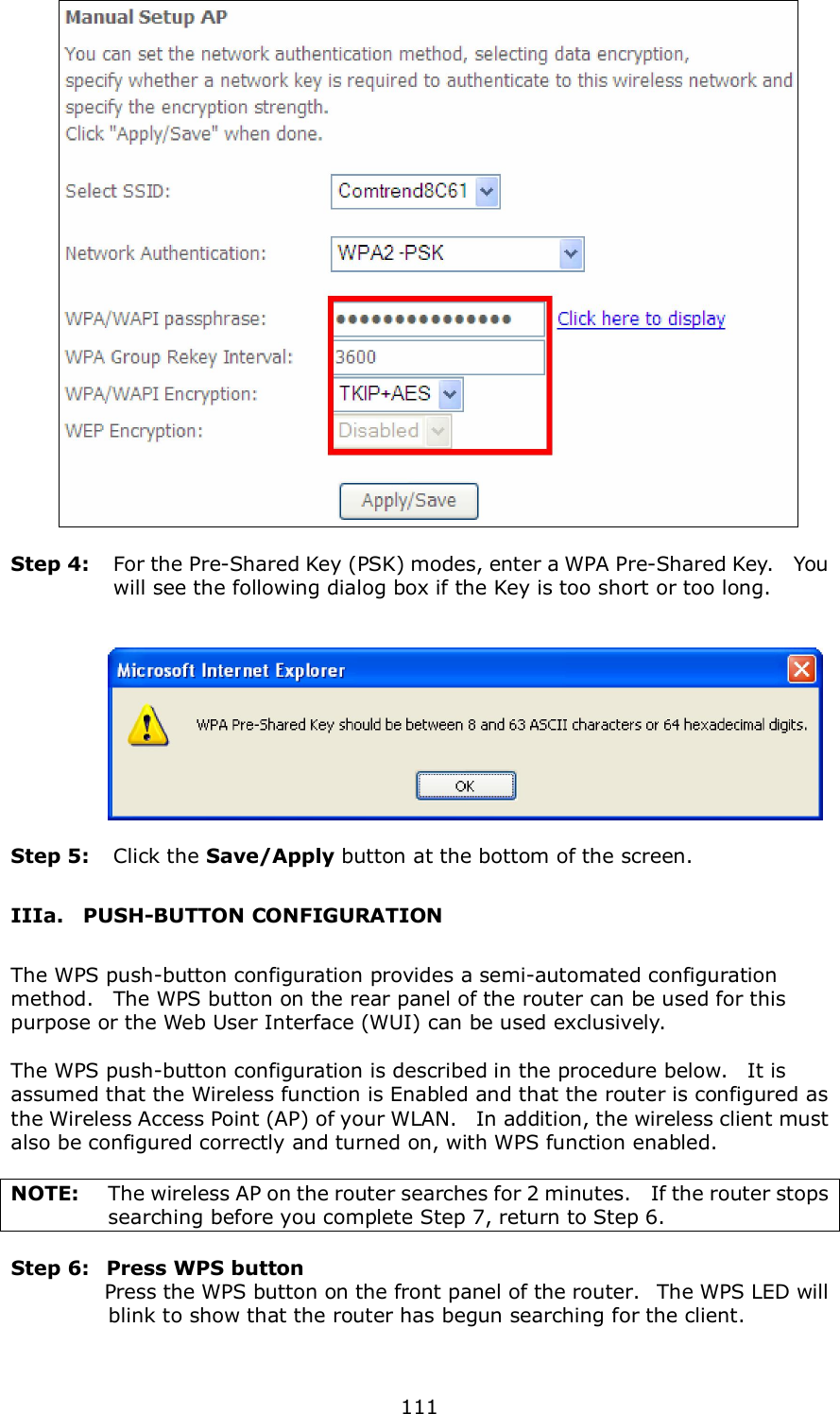
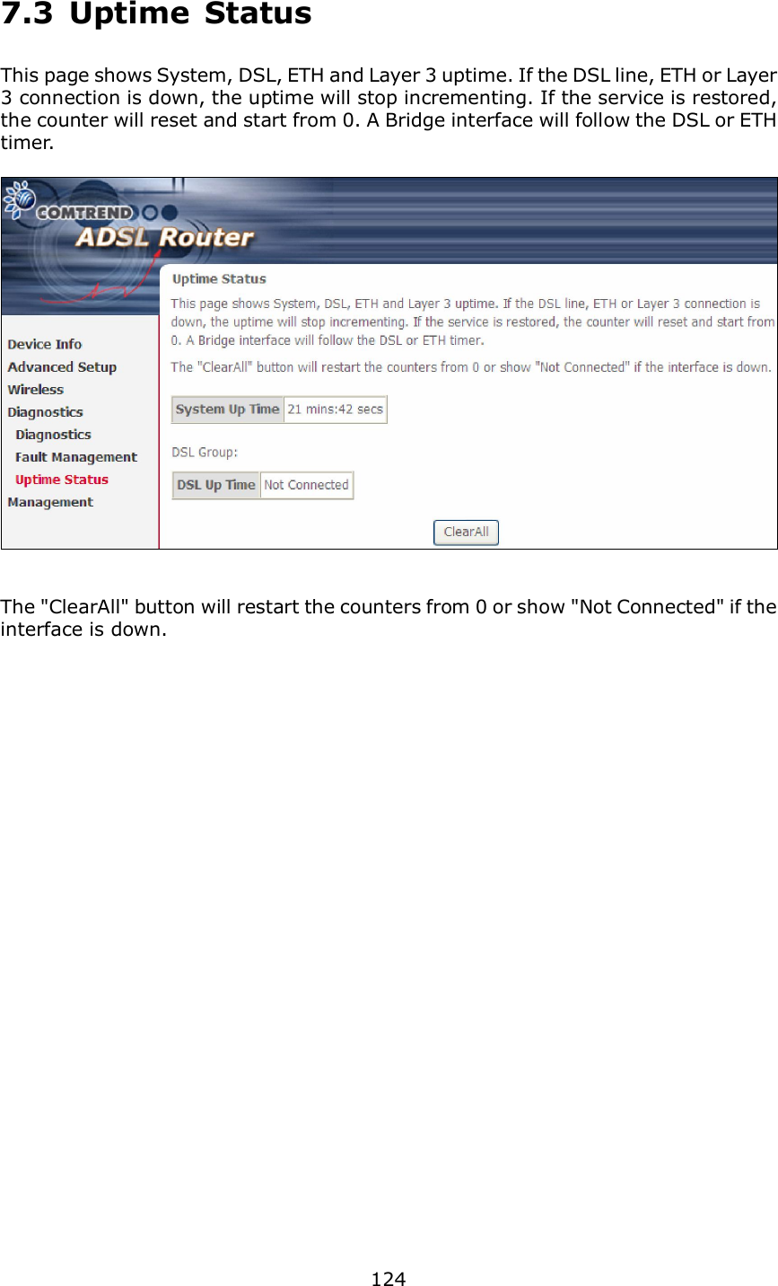
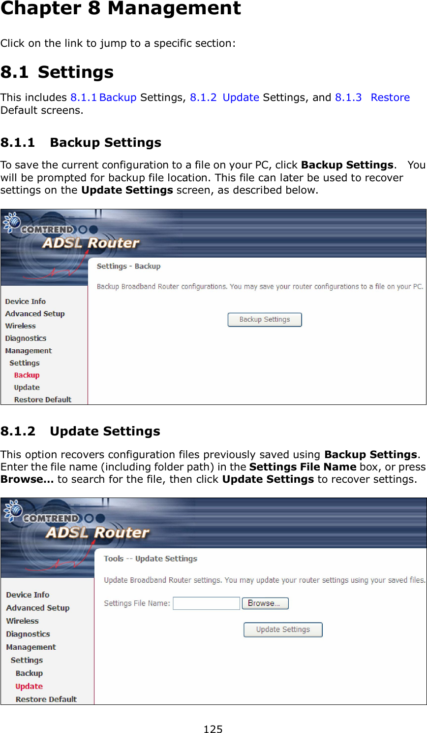
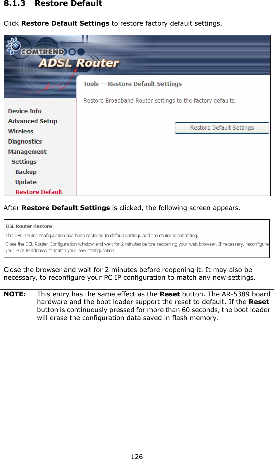
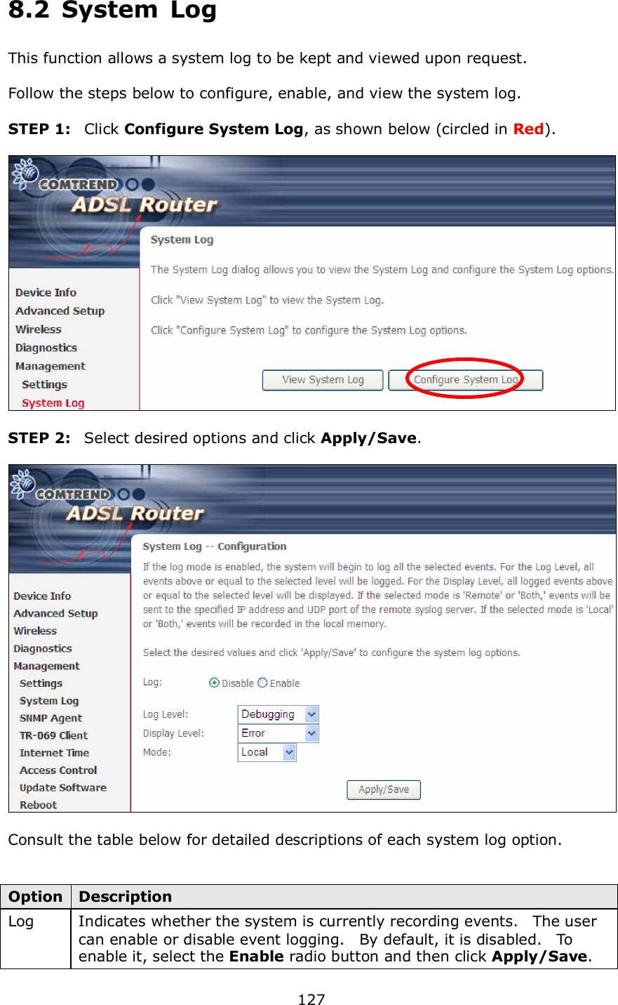
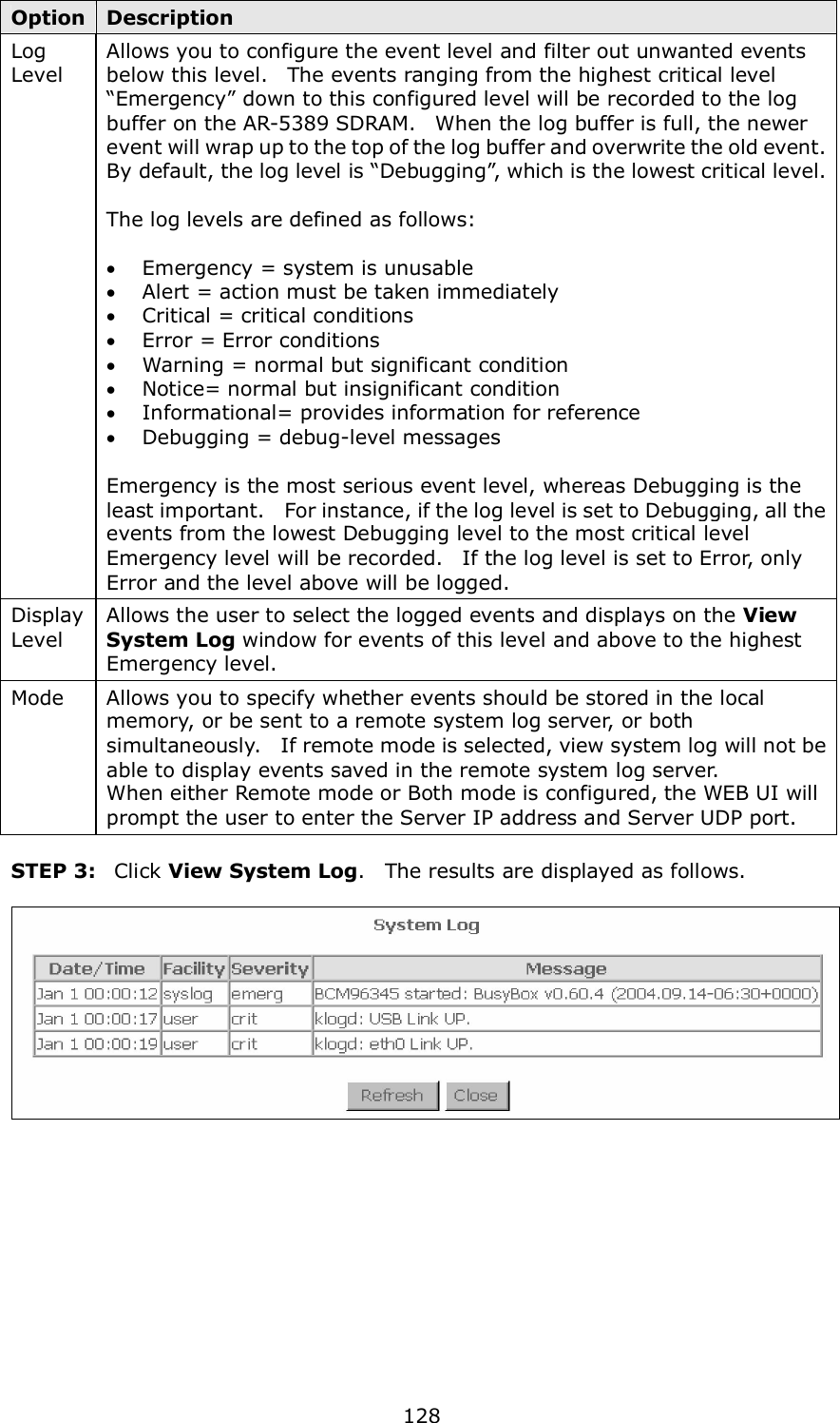
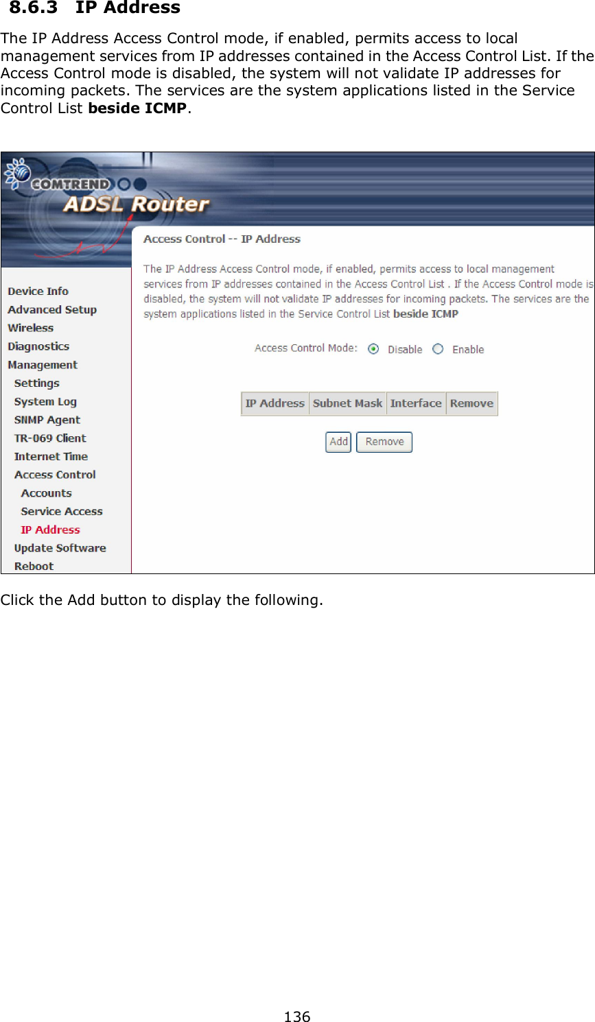
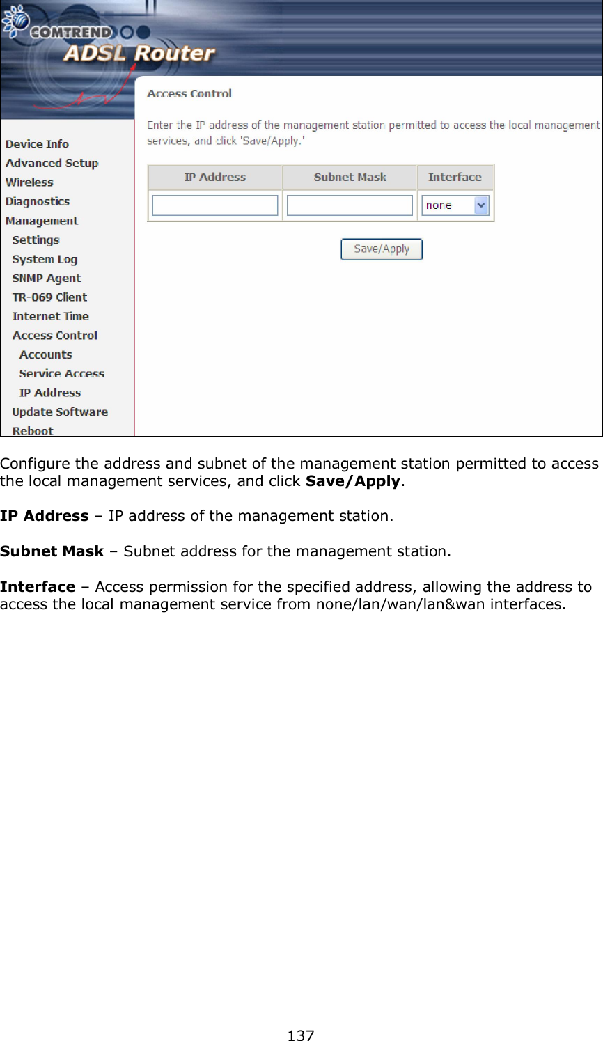
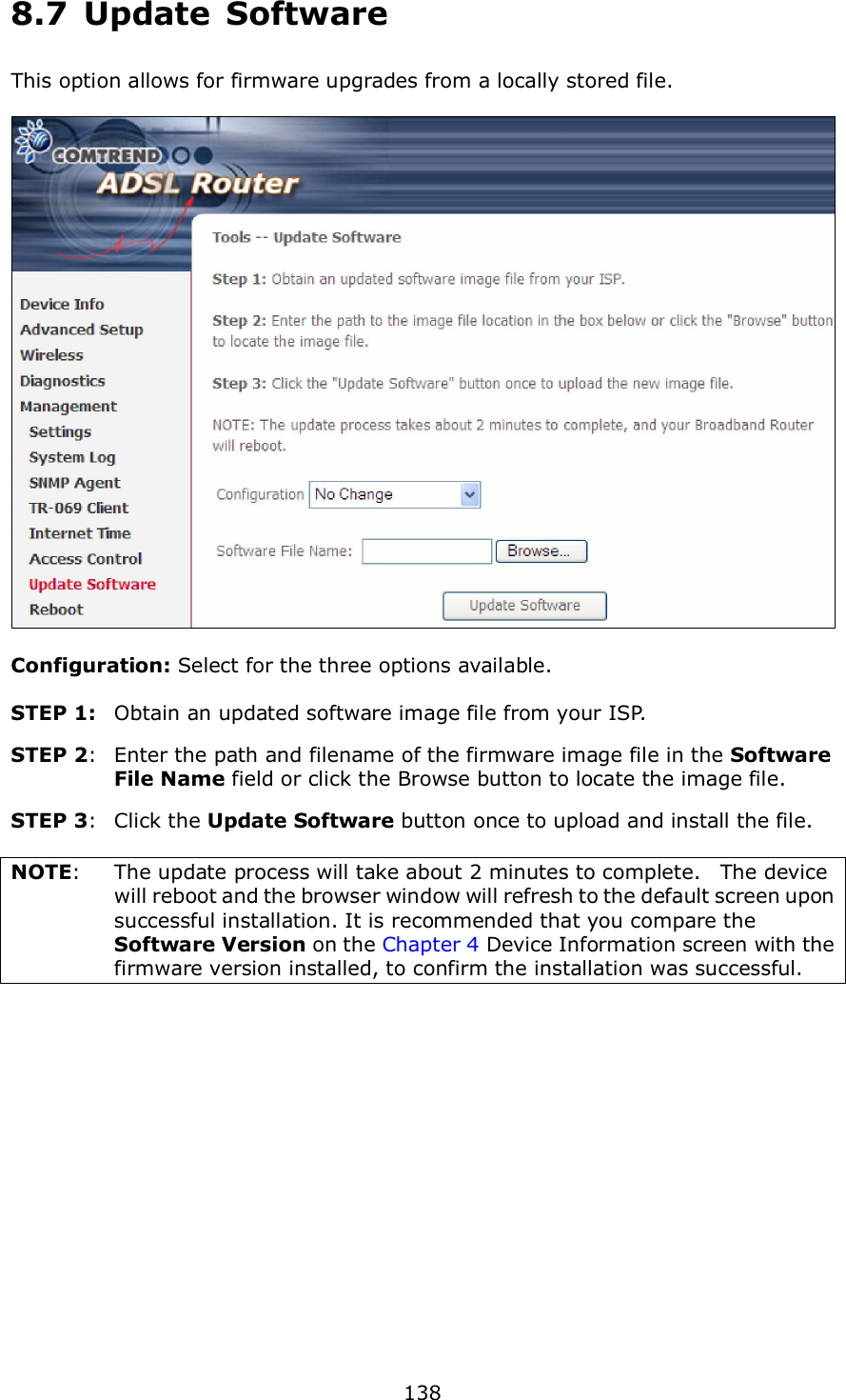
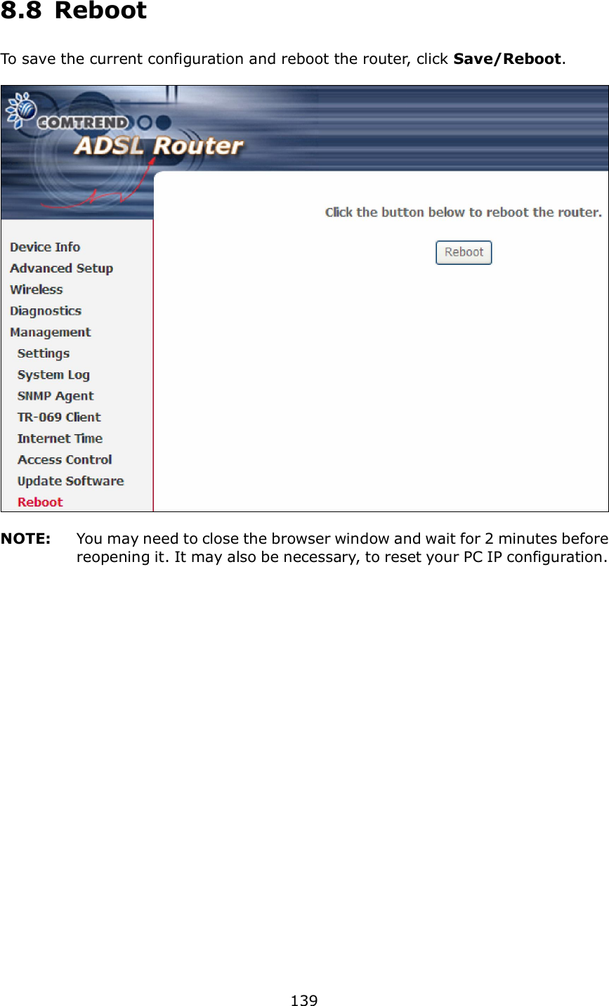
![123 7.2 Fault Management Please note this function is not available on the AR-5389. Item Description Maintenance Domain (MD) Level Management space on the network, the larger the domain, the higher the level value Destination MAC Address Destination MAC address for sending the loopback message 802.1Q VLAN ID: [0-4095] 802.1Q VLAN used in VDSL PTM mode Set MD Level Save the Maintenance domain level. Send Loopback Send loopback message to destination MAC address. Send Linktrace Send traceroute message to destination MAC address.](https://usermanual.wiki/Comtrend/AR-5389.AR-5389-user-manual-3/User-Guide-1971704-Page-25.png)