Contents
- 1. AR-5389_user manual-1
- 2. AR-5389_user manual-2
- 3. AR-5389_user manual-3
- 4. AR-5389_user manual-4
AR-5389_user manual-3
99
Auto(IKE) Key Exchange Method
Pre-Shared Key / Certificate (X.509)
Input Pre-shared key / Choose Certificate
Perfect Forward Secrecy Enable or Disable
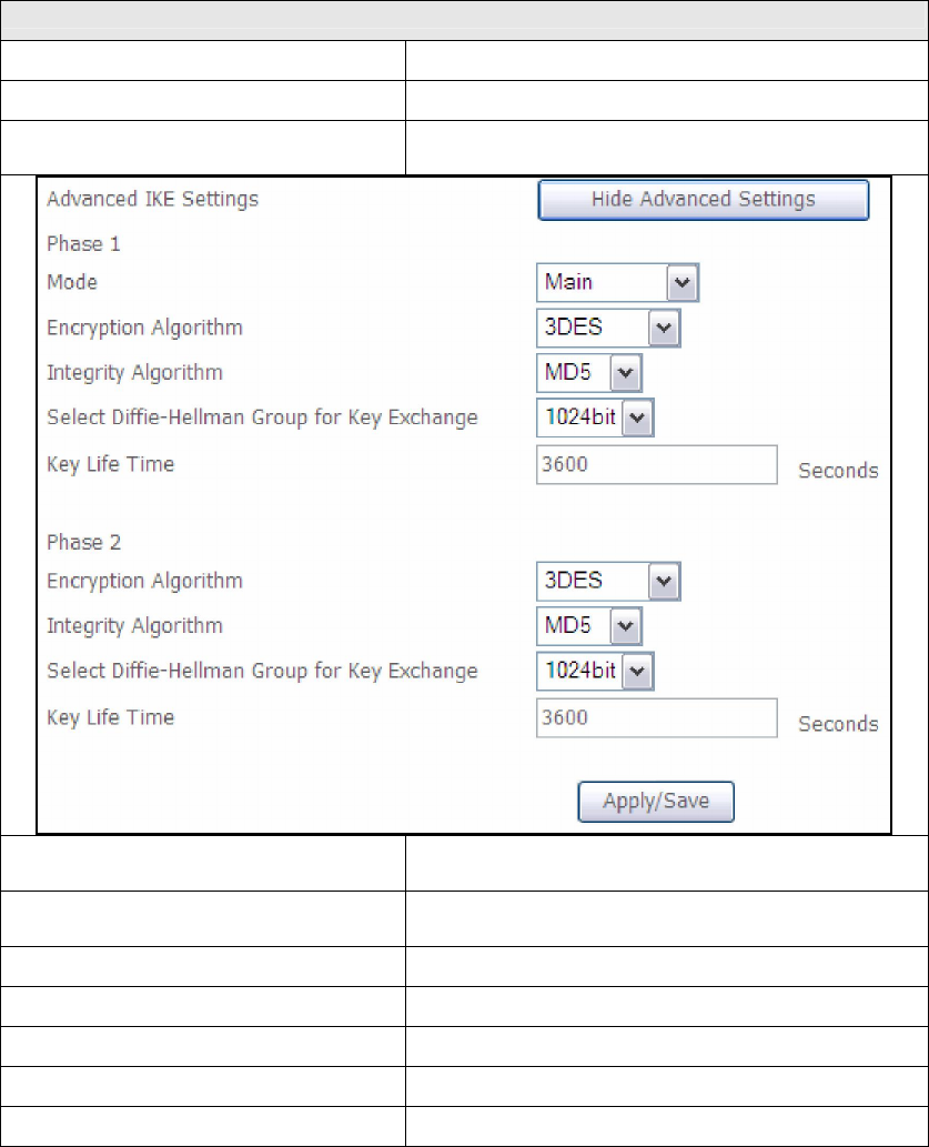
Advanced IKE Settings Select Show Advanced Settings to reveal
the advanced settings options shown below.
Advanced IKE Settings Select Hide Advanced Settings to hide the
advanced settings options shown above.
Phase 1 / Phase 2 Choose settings for each phase, the available
options are separated with a “/” character.
Mode Main / Aggressive
Encryption Algorithm DES / 3DES / AES 128,192,256
Integrity Algorithm MD5 / SHA1
Select Diffie-Hellman Group 768 – 8192 bit
Key Life Time Enter your own or use the default (1 hour)
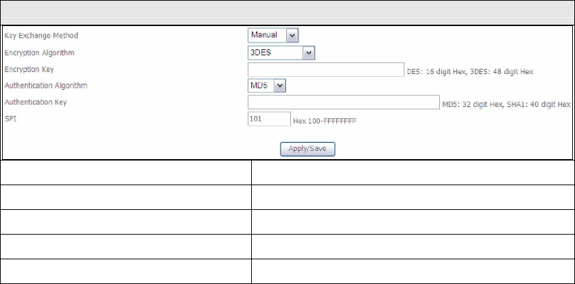
The Manual key exchange method options are summarized in the table below.
100
Manual Key Exchange Method
Encryption Algorithm DES / 3DES / AES (aes-cbc)
Encryption Key DES: 16 digit Hex, 3DES: 48 digit Hex
Authentication Algorithm MD5 / SHA1
Authentication Key MD5: 32 digit Hex, SHA1: 40 digit Hex
SPI (default is 101) Enter a Hex value from 100-FFFFFFFF
101
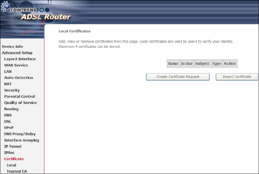
5.17 Certificate
A certificate is a public key, attached with its owner’s information (company name,
server name, personal real name, contact e-mail, postal address, etc) and digital
signatures. There will be one or more digital signatures attached to the certificate,
indicating that these entities have verified that this certificate is valid.
5.17.1 Local
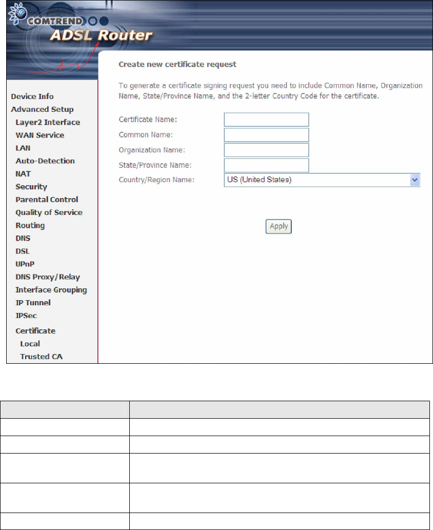
CREATE CERTIFICATE REQUEST
Click Create Certificate Request to generate a certificate-signing request.
The certificate-signing request can be submitted to the vendor/ISP/ITSP to apply for
a certificate. Some information must be included in the certificate-signing request.
Your vendor/ISP/ITSP will ask you to provide the information they require and to
provide the information in the format they regulate. Enter the required information
and click Apply to generate a private key and a certificate-signing request.
102
The following table is provided for your reference.
Field Description
Certificate Name A user-defined name for the certificate.
Common Name
Usually, the fully qualified domain name for the machine.
Organization Name The exact legal name of your organization.
Do not abbreviate.
State/Province Name The state or
province where your organization is located.
It cannot be abbreviated.
Country/Region Name The two-letter ISO abbreviation for your country.
103
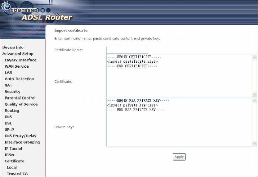
IMPORT CERTIFICATE
Click Import Certificate to paste the certificate content and the private key
provided by your vendor/ISP/ITSP into the corresponding boxes shown below.
Enter a certificate name and click Apply to import the local certificate.
104
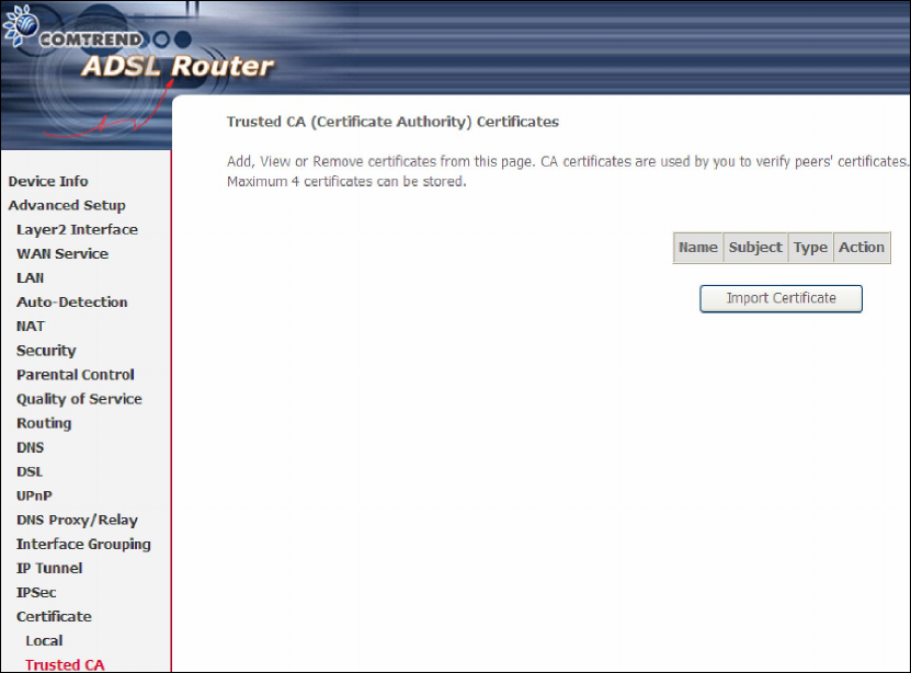
5.17.2 Trusted CA
CA is an abbreviation for Certificate Authority, which is a part of the X.509 system.
It is itself a certificate, attached with the owner information of this certificate
authority; but its purpose is not encryption/decryption. Its purpose is to sign and
issue certificates, in order to prove that these certificates are valid.
Click Import Certificate to paste the certificate content of your trusted CA. The
CA certificate content will be provided by your vendor/ISP/ITSP and is used to
authenticate the Auto-Configuration Server (ACS) that the CPE will connect to.
105
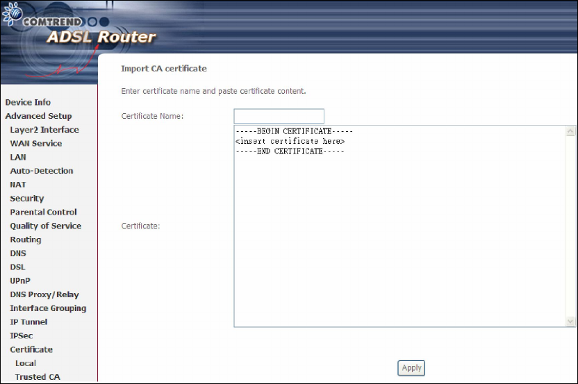
Enter a certificate name and click Apply to import the CA certificate.
106
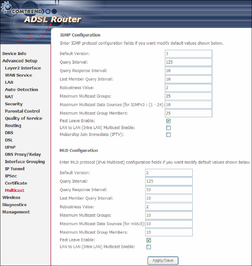
5.18 Multicast
Input new IGMP or MLD protocol configuration fields if you want modify default
values shown. Then click Apply/Save.
107
Chapter 6 Wireless
The Wireless menu provides access to the wireless options discussed below.
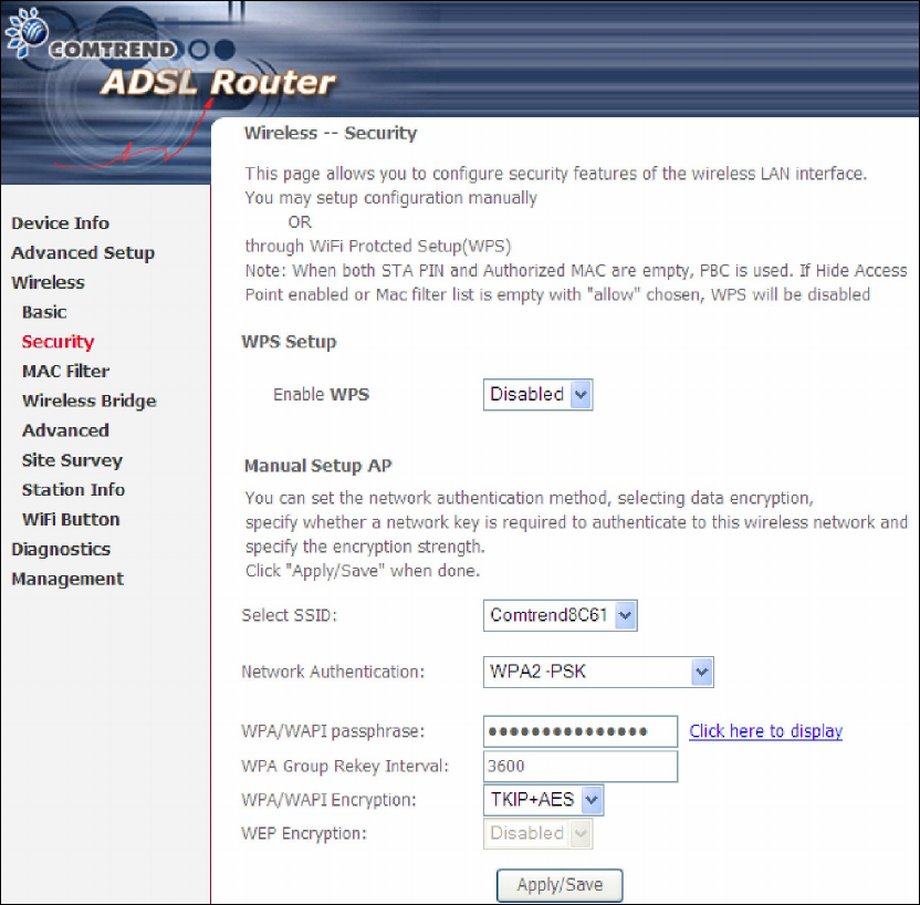
6.1 Security
The following screen appears when Wireless Security is selected. The options shown
here allow you to configure security features of the wireless LAN interface.
Click Save/Apply to implement new configuration settings.
WIRELESS SECURITY
Wireless security settings can be configured according to Wi-Fi Protected Setup
(WPS) or Manual Setup. The WPS method configures security settings automatically
(see 6.1.1 WPS) while the Manual Setup method requires that the user configure
these settings using the Web User Interface (see the table below).
108
Select SSID
Select the wireless network name from the drop-
down box. SSID stands for Service
Set Identifier. All stations must be configured wit
h the correct SSID to access the
WLAN. If the SSID does not match, that client will not be granted access.
Network Authentication
This option specifies whether a network key is used for authentication to the
wireless network. If network authenticat
ion is set to Open, then no authentication
is provided. Despite this, the identity of the client is still verified.
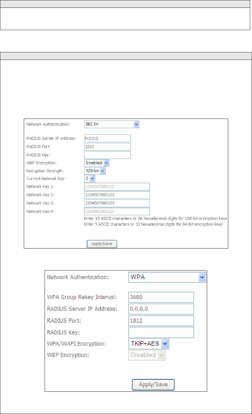
Each authentication type has its own settings. For example, selecting 802.1X
authentication will reveal the RADIUS Server IP address, P
ort and Key fields. WEP
Encryption will also be enabled as shown below.
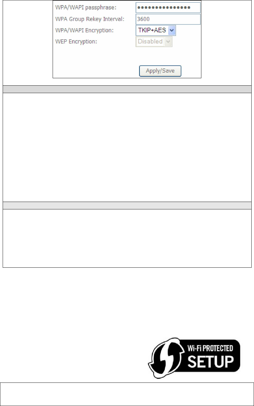
The settings for WPA authentication are shown below.
The settings for WPA-PSK authentication are shown next.
109
WEP Encryption
This option specifies whether data sent over the network is encrypted. The same
network key is used for data encryption and network authentication. Four network
keys can be defined although only one can be used at any one time. Use the Current
Network Key list box to select the appropriate network key.
Security options include authentication and encryption services based on the wired
equivalent privacy (WEP) algorithm. WEP is a set of security services used to
protect 802.11 networks from unauthorized access, such as eavesdropping
; in this
case, the capture of wireless network traffic. When data encryption is enabled,
secret shared encryption keys are generated and used by the source station and the
destination station to alter frame bits, thus avoiding disclosure to eavesdroppers.
Under shared key authentication, each wireless station is assumed to have received
a secret shared key over a secure channel that is independent from the 802.11
wireless network communications channel.
Encryption Strength
This drop-down list box will display when WEP Encryption is enabled. The key
strength is proportional to the number of binary bits comprising the key. This
means that keys with a greater number of bits have a greater degree of security and
are considerably more difficult to crack. Encryption strength can be set to either
64-bit or 128-bit. A 64-bit key is equivalent to 5 ASCII characters or 10
hexadecimal numbers. A 128-bit key contains 13 ASCII characters or 26
hexadecimal numbers. Each key contains a 24-bit header (an initiation vector)
which enables parallel decoding of multiple streams of encrypted data.
6.1.1 WPS
Wi-Fi Protected Setup (WPS) is an industry standard that simplifies wireless security
setup for certified network devices. Every WPS certified device has a PIN number
accessed through device software. The AR-5389 has a virtual button accessible from
the web user interface (WUI).
Devices with the WPS logo (shown here)
support WPS. If the WPS logo is not present
on your device it still may support WPS, in
this case, check the device documentation
for the phrase “Wi-Fi Protected Setup”.
NOTE: WPS is only available in Open, WPA-PSK, WPA2-PSK and Mixed
WPA2/WPA-PSK network authentication modes. Other authentication
modes do not use WPS so they must be configured manually.
110
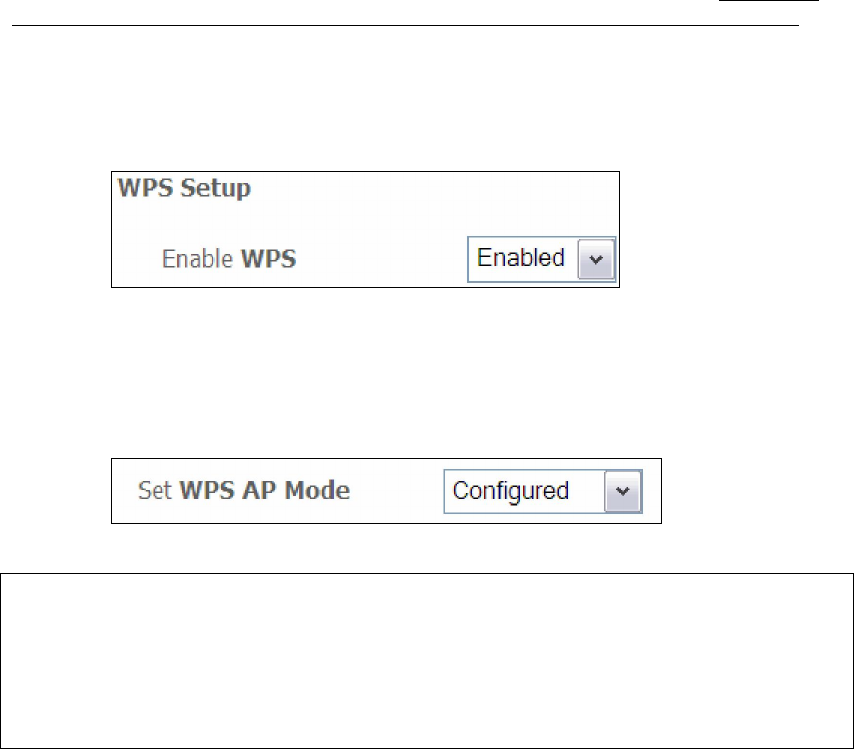
To configure security settings with WPS, follow the procedures below. You must
choose either the Push-Button or PIN configuration method for Steps 6 and 7.
I. Setup
Step 1: Enable WPS by selecting Enabled from the drop down list box shown.
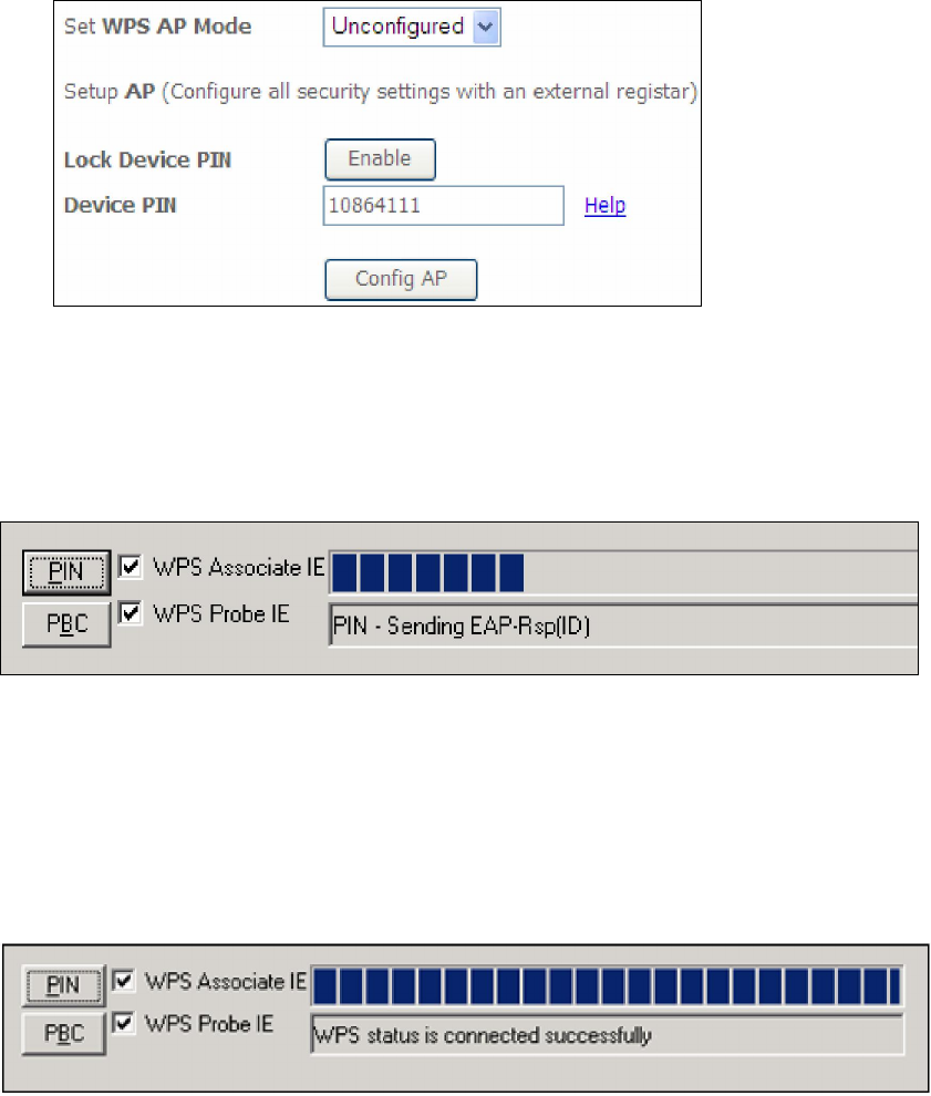
Step 2: Set the WPS AP Mode. Configured is used when the AR-5389 will assign
security settings to clients. Unconfigured is used when an external
client assigns security settings to the AR-5389.
NOTES: Your client may or may not have the ability to provide security settings to
the AR-5389. If it does not, then you must set the WPS AP mode to
Configured. Consult the device documentation to check its capabilities.
In addition, using Windows Vista, you can add an external registrar using
the StartAddER button (Appendix D - WPS OPERATION) has detailed
instructions).
II. NETWORK AUTHENTICATION
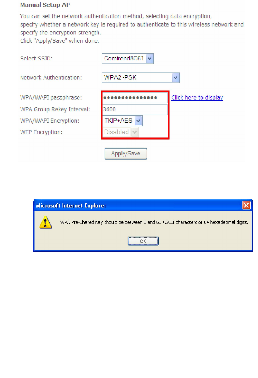
Step 3: Select Open, WPA-PSK, WPA2-PSK, or Mixed WPA2/WPA-PSK network
authentication mode from the Manual Setup AP section of the Wireless
Security screen. The example below shows WPA2-PSK mode.
111
Step 4: For the Pre-Shared Key (PSK) modes, enter a WPA Pre-Shared Key. You
will see the following dialog box if the Key is too short or too long.
Step 5: Click the Save/Apply button at the bottom of the screen.
IIIa. PUSH-BUTTON CONFIGURATION
The WPS push-button configuration provides a semi-automated configuration
method. The WPS button on the rear panel of the router can be used for this
purpose or the Web User Interface (WUI) can be used exclusively.
The WPS push-button configuration is described in the procedure below. It is
assumed that the Wireless function is Enabled and that the router is configured as
the Wireless Access Point (AP) of your WLAN. In addition, the wireless client must
also be configured correctly and turned on, with WPS function enabled.
NOTE: The wireless AP on the router searches for 2 minutes. If the router stops
searching before you complete Step 7, return to Step 6.
Step 6: Press WPS button
Press the WPS button on the front panel of the router. The WPS LED will
blink to show that the router has begun searching for the client.
112
Step 7: Go to your WPS wireless client and activate the push-button function.
A typical WPS client screenshot is shown below as an example.
Now go to Step 8 (part IV. Check Connection) to check the WPS connection.
IIIb. WPS – PIN CONFIGURATION
Using this method, security settings are configured with a personal identification
number (PIN). The PIN can be found on the device itself or within the software.
The PIN may be generated randomly in the latter case. To obtain a PIN number for
your client, check the device documentation for specific instructions.
The WPS PIN configuration is described in the procedure below. It is assumed that
the Wireless function is Enabled and that the router is configured as the Wireless
Access Point (AP) of your wireless LAN. In addition, the wireless client must also be
configured correctly and turned on, with WPS function enabled.
NOTE: Unlike the push-button method, the pin method has no set time limit.
This means that the router will continue searching until it finds a client.
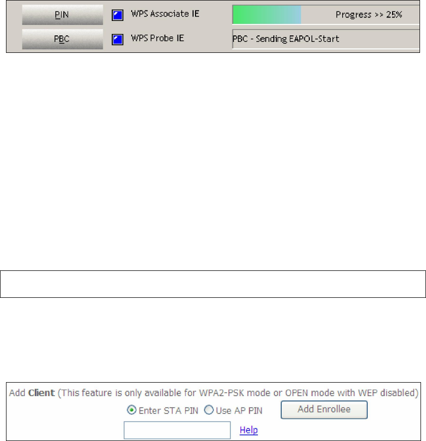
Step 6: Select the PIN radio button in the WSC Setup section of the Wireless
Security screen, as shown in A or B below, and then click the appropriate
button based on the WSC AP mode selected in step 2.
A - For Configured mode, click the Add Enrollee button.
Enter STA PIN: a Personal Identification Number (PIN) has to be read from either
a sticker or the display on the new wireless device. This PIN must then be inputted
at representing the network, usually the Access Point of the network.
B - For Unconfigured mode, click the Config AP button.
113
Step 7: Activate the PIN function on the wireless client. For Configured mode,
the client must be configured as an Enrollee. For Unconfigured mode,
the client must be configured as the Registrar. This is different from the
External Registrar function provided in Windows Vista.
The figure below provides an example of a WPS client PIN function in-progress.
Now go to Step 8 (part IV. Check Connection) to check the WPS connection.
IV. CHECK CONNECTION
Step 8: If the WPS setup method was successful, you will be able access the
wireless AP from the client. The client software should show the status.
The example below shows that the connection established successfully.
You can also double-click the Wireless Network Connection icon from the
Network Connections window (or the system tray) to confirm the status of
the new connection.
114
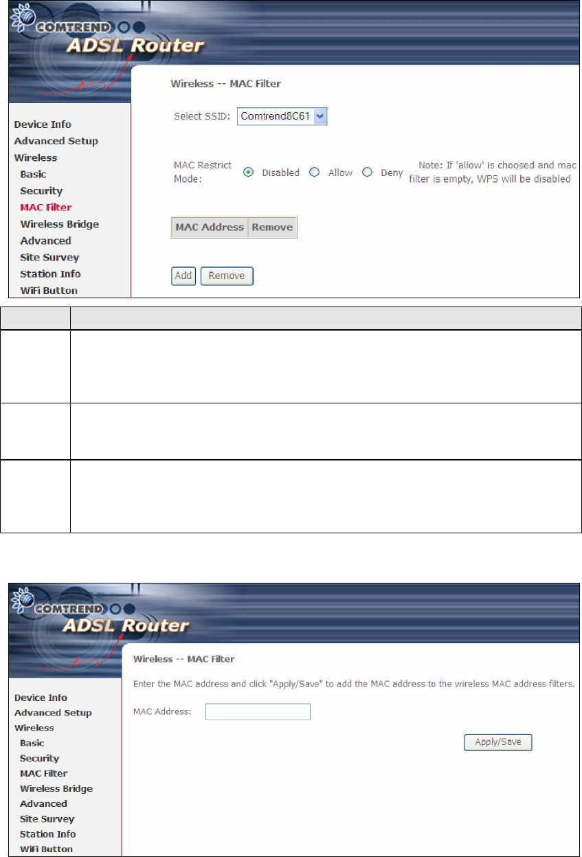
6.2 MAC Filter
This option allows access to the router to be restricted based upon MAC addresses.
To add a MAC Address filter, click the Add button shown below. To delete a filter,
select it from the MAC Address table below and click the Remove button.
Option
Description
Select
SSID
Select the wireless network name from the drop-down box. SSID stands
for Service Set Identifier. All stations must be configured with the correct
SSID to access the WLAN. If the SSID does not match, that user will not
be granted access.
MAC
Restrict
Mode
Disabled: MAC filtering is disabled.
Allow: Permits access for the specified MAC addresses.
Deny: Rejects access for the specified MAC addresses.
MAC
Address
Lists the MAC addresses subject to the MAC Restrict Mode. A maximum
of 60 MAC addresses can be added. Every network device has a unique
48-bit MAC address. This is usually shown as xx.xx.xx.xx.xx.xx, where
xx are hexadecimal numbers.
After clicking the Add button, the following screen appears.
Enter the MAC address in the box provided and click Save/Apply.
115
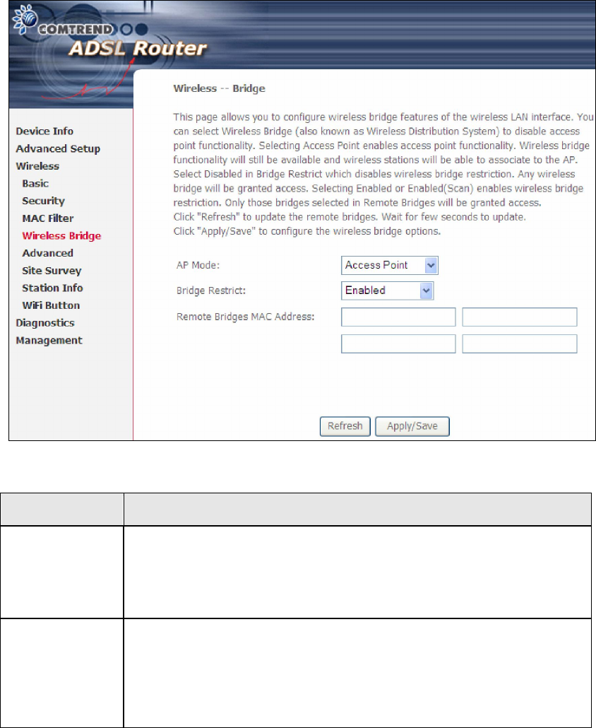
6.3 Wireless Bridge
This screen allows for the configuration of wireless bridge features of the WIFI
interface. See the table beneath for detailed explanations of the various options.
Click Save/Apply to implement new configuration settings.
Feature Description
AP Mode Selecting Wireless Bridge (aka Wireless Distribution System)
disables Access Point (AP) functionality, while selecting Access
Point enables AP functionality. In Access Point mode, wireless
bridge functionality will still be available and wireless stations
will be able to associate to the AP.
Bridge Restrict
Selecting Disabled disables wireless bridge restriction, which
means that any wireless bridge will be granted access.
Selecting Enabled or Enabled (Scan) enables wireless bridge
restriction. Only those bridges selected in the Remote Bridges
list will be granted access. Click Refresh to update the station
list when Bridge Restrict is enabled.
116
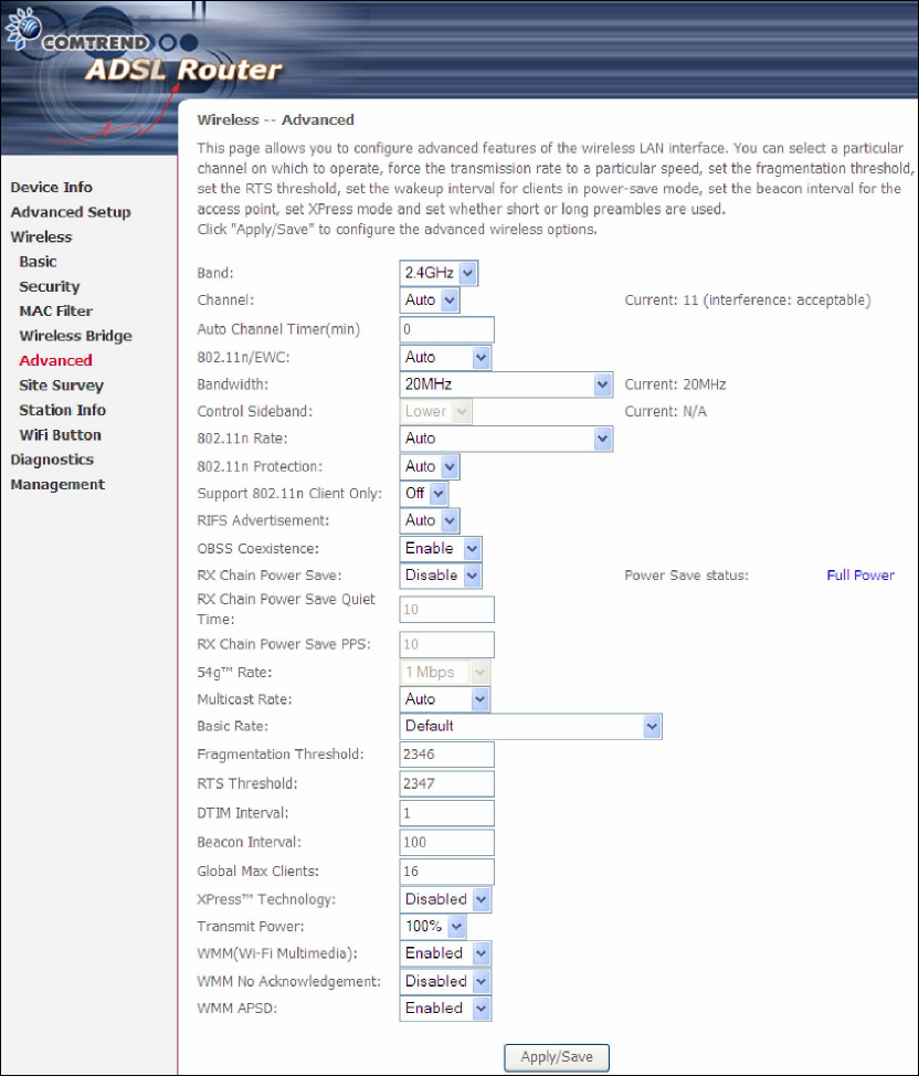
6.4 Advanced
The Advanced screen allows you to configure advanced features of the wireless LAN
interface. You can select a particular channel on which to operate, force the
transmission rate to a particular speed, set the fragmentation threshold, set the RTS
threshold, set the wakeup interval for clients in power-save mode, set the beacon
interval for the access point, set XPress mode and set whether short or long
preambles are used. Click Save/Apply to set new advanced wireless options.

117
Field Description
Band Set to 2.4 GHz for compatibility with IEEE 802.11x
standards. The new amendment allows IEEE 802.11n
units to fall back to slower speeds so that legacy IEEE
802.11x devices can coexist in the same network. IEEE
802.11g creates data-rate parity at 2.4 GHz with the IEEE
802.11a standard, which has a 54 Mbps rate at 5 GHz.
(IEEE 802.11a has other differences compared to IEEE
802.11b or g, such as offering more channels.)
Channel Drop-down menu that allows selection of a specific
channel.
Auto Channel Timer
(min)
Auto channel scan timer in minutes (0 to disable)
802.11n/EWC An equipment interoperability standard setting based on
IEEE 802.11n Draft 2.0 and Enhanced Wireless
Consortium (EWC)
Bandwidth Select 20GHz or 40GHz bandwidth. 40GHz bandwidth uses
two adjacent 20GHz bands for increased data throughput.
Control Sideband Select Upper or Lower sideband when in 40GHz mode.
802.11n Rate Set the physical transmission rate (PHY).
802.11n Protection Turn Off for maximized throughput.
Turn On for greater security.
Support 802.11n
Client Only
Turn Off to allow 802.11b/g clients access to the router.
Turn On to prohibit 802.11b/g clients access to the router.
RIFS Advertisement One of several draft-n features designed to improve
efficiency. Provides a shorter delay between OFDM
transmissions than in802.11a or g.
OBSS Co-Existence Co-existence between 20 MHZ AND 40 MHZ overlapping
Basic Service Set (OBSS) in WLAN.
RX Chain Power Save Enabling this feature turns off one of the Receive chains,
going from 2x2 to 2x1 to save power.
RX Chain Power Save
Quiet Time
The number of seconds the traffic must be below the PPS
value below before the Rx Chain Power Save feature
activates itself.
RX Chain Power Save
PPS
The maximum number of packets per seconds that can be
processed by the WLAN interface for a duration of Quiet
Time, described above, before the Rx Chain Power Save
feature activates itself.
54g Rate Drop-
down menu that specifies the following fixed rates:
Auto: Default. Uses the 11 Mbps data rate when possible
but drops to lower rates when necessary. 1 Mbps, 2Mbps,
5.5Mbps, or 11Mbps fixed rates. The appropriate setting
is dependent on signal strength.
Multicast Rate Setting for multicast packet transmit rate (1-54 Mbps)
Basic Rate Setting for basic transmission rate.

118
Field Description
Fragmentation
Threshold
A threshold, specified in bytes, that determines whether
packets will be fragmented and at what size. On an
802.11 WLAN, packets that exceed the fragmentation
threshold are fragmented, i.e., split into, smaller units
suitable for the circuit size. Packets smaller than the
specified fragmentation threshold value are not
fragmented. Enter a value between 256 and 2346. If you
experience a high packet error rate, try to slightly increase
your Fragmentation Threshold. The value should remain
at its default setting of 2346. Setting the Fragmentation
Threshold too low may result in poor performance.
RTS Threshold Request to Send, when set in bytes, specifies the packet
size beyond which the WLAN Card invokes its RTS/CTS
mechanism. Packets that exceed the specified RTS
threshold trigger the RTS/CTS mechanism. The NIC
transmits smaller packet without using RTS/CTS. The
default setting of 2347 (maximum length) disables RTS
Threshold.
DTIM Interval Delivery Traffic Indication Message (DTIM) is also known
as Beacon Rate. The entry range is a value between 1
and 65535. A DTIM is a countdown variable that informs
clients of the next window for listening to broadcast and
multicast messages. When the AP has buffered
broadcast or multicast messages for associated clients, it
sends the next DTIM with a DTIM Interval value. AP
Clients hear the beacons and awaken to receive the
broadcast and multicast messages. The default is 1.
Beacon Interval The amount of time between beacon transmissions in
milliseconds. The default is 100 ms and the acceptable
range is 1 – 65535. The beacon transmissions identify
the presence of an access point. By default, network
devices passively scan all RF channels listening for
beacons coming from access points. Before a station
enters power save mode, the station needs the beacon
interval to know when to wake up to receive the beacon
(and learn whether there are buffered frames at the
access point).
Global Max Clients The maximum number of clients that can connect to the
router.
Xpress TM Technology Xpress Technology is compliant with draft specifications of
two planned wireless industry standards.
Transmit Power Set the power output (by percentage) as desired.
WMM (Wi-Fi
Multimedia)
The technology maintains the priority of audio, video and
voice applications in a Wi-Fi network. It allows multimedia
service get higher priority.
WMM No
Acknowledgement
Refers to the acknowledge policy used at the MAC level.
Enabling no Acknowledgement can result in more efficient
throughput but higher error rates in a noisy Radio
Frequency (RF) environment.
WMM APSD This is Automatic Power Save Delivery. It saves power.
119
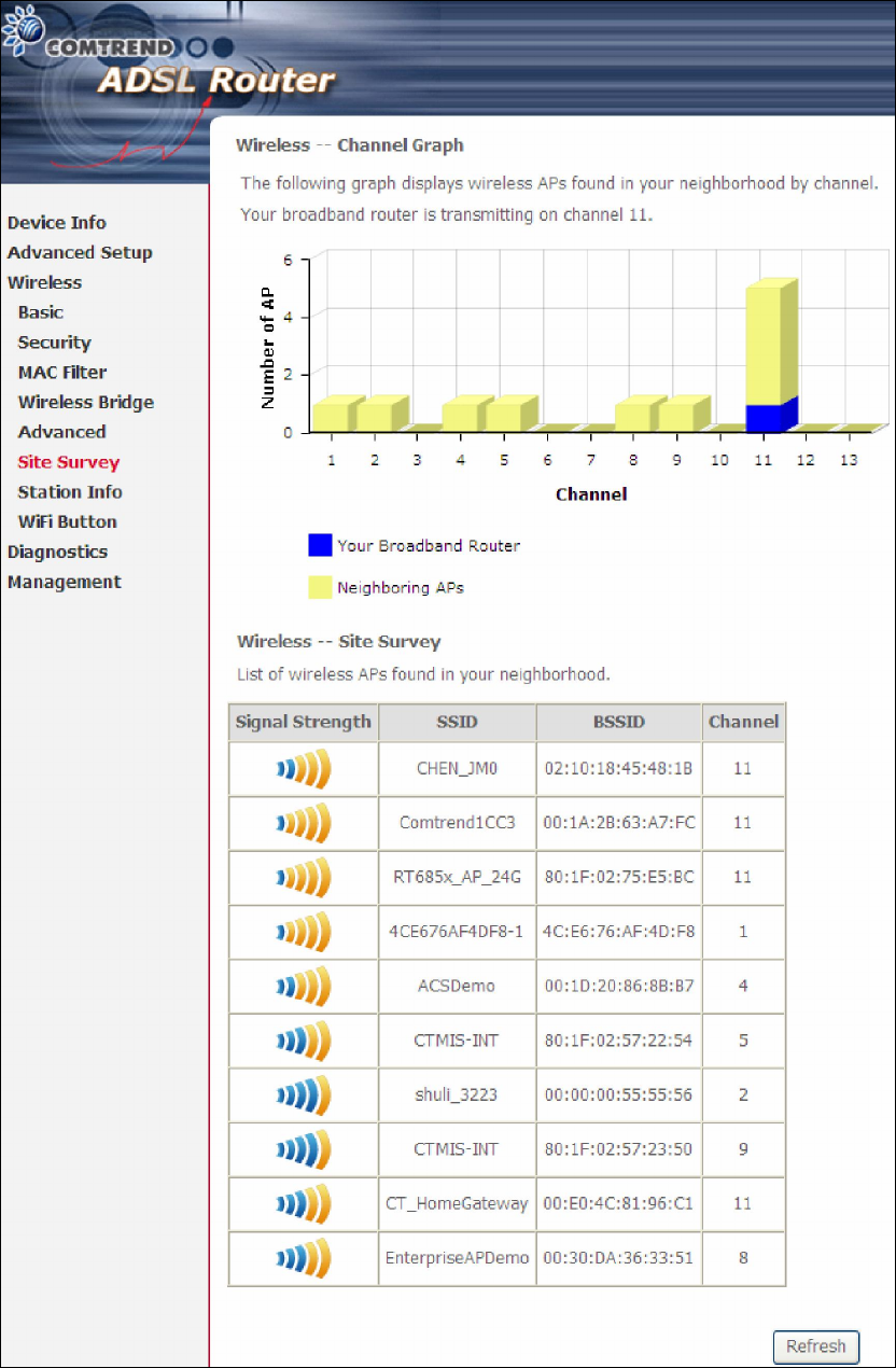
6.5 Site Survey
The following graph displays wireless APs found in your neighborhood by channel.
120
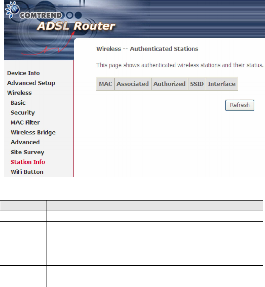
6.6 Station Info
This page shows authenticated wireless stations and their status. Click the Refresh
button to update the list of stations in the WLAN.
Consult the table below for descriptions of each column heading.
Heading Description
MAC Lists the MAC address of all the stations.
Associated Lists all the stations that are associated with the Access
Point, along with the amount of time since packets were transferred
to and from each station. If a station is idle for too long, it is
removed from this list.
Authorized Lists those devices with authorized access.
SSID Lists which SSID of the modem that the stations connect to.
Interface Lists which interface of the modem that the stations connect to.
121
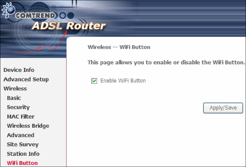
6.7 WiFi Button
This page allows you to enable or disable the WiFi Button.
122
Chapter 7 Diagnostics
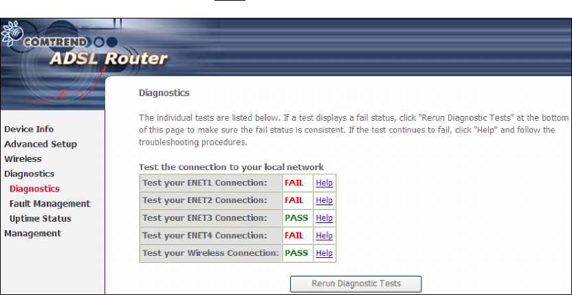
7.1 Diagnostics – Individual Tests
The first Diagnostics screen is a dashboard that shows overall connection status.
If a test displays a fail status, click the button to retest and confirm the error.
If a test continues to fail, click Help and follow the troubleshooting procedures.
123
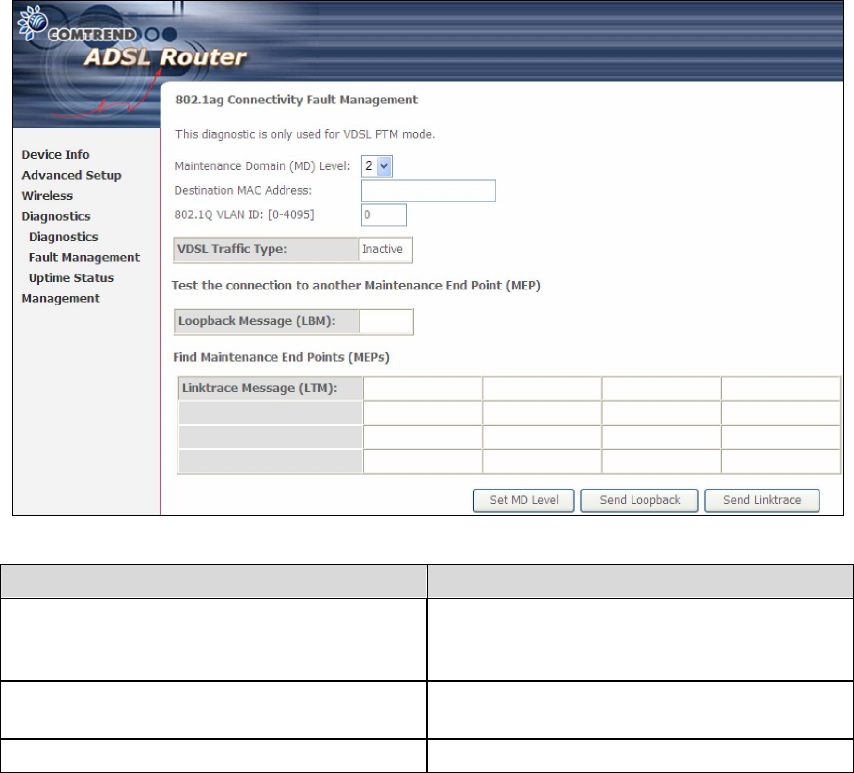
7.2 Fault Management
Please note this function is not available on the AR-5389.
Item Description
Maintenance Domain (MD) Level Management space on the network, the
larger the domain, the higher the level
value
Destination MAC Address Destination MAC address for sending the
loopback message
802.1Q VLAN ID: [0-4095] 802.1Q VLAN used in VDSL PTM mode
Set MD Level
Save the Maintenance domain level.
Send Loopback
Send loopback message to destination MAC address.
Send Linktrace
Send traceroute message to destination MAC address.
124
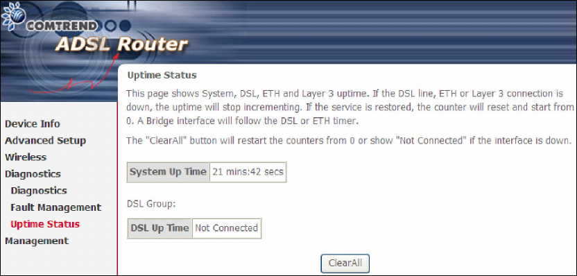
7.3 Uptime Status
This page shows System, DSL, ETH and Layer 3 uptime. If the DSL line, ETH or Layer
3 connection is down, the uptime will stop incrementing. If the service is restored,
the counter will reset and start from 0. A Bridge interface will follow the DSL or ETH
timer.
The "ClearAll" button will restart the counters from 0 or show "Not Connected" if the
interface is down.
125
Chapter 8 Management
Click on the link to jump to a specific section:
8.1 Settings
This includes 8.1.1 Backup Settings, 8.1.2 Update Settings, and 8.1.3 Restore
Default screens.
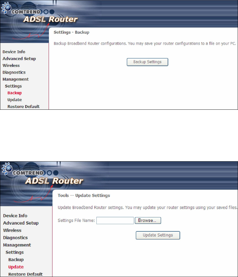
8.1.1 Backup Settings
To save the current configuration to a file on your PC, click Backup Settings. You
will be prompted for backup file location. This file can later be used to recover
settings on the Update Settings screen, as described below.
8.1.2 Update Settings
This option recovers configuration files previously saved using Backup Settings.
Enter the file name (including folder path) in the Settings File Name box, or press
Browse… to search for the file, then click Update Settings to recover settings.
126
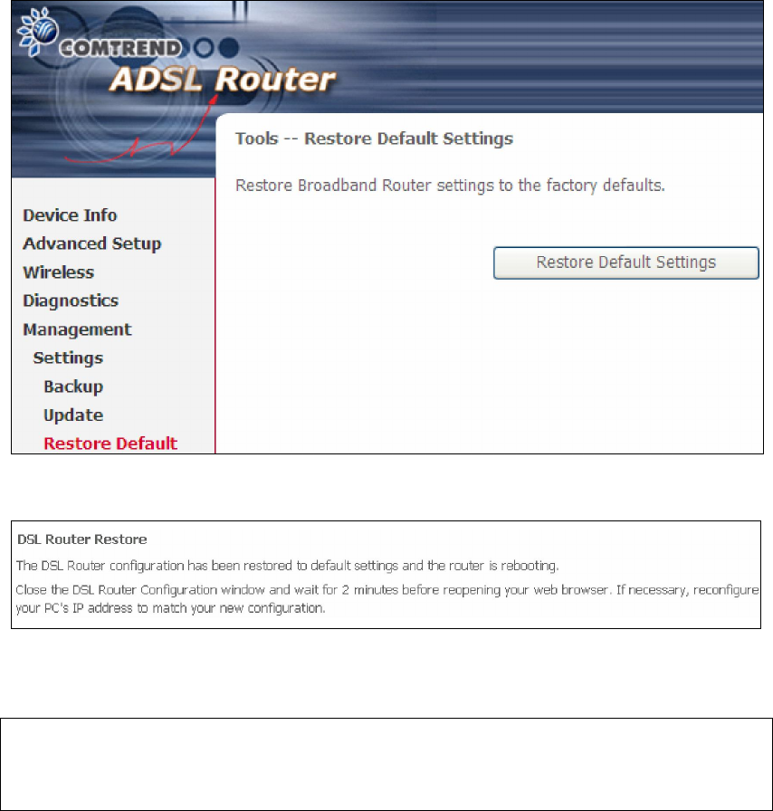
8.1.3 Restore Default
Click Restore Default Settings to restore factory default settings.
After Restore Default Settings is clicked, the following screen appears.
Close the browser and wait for 2 minutes before reopening it. It may also be
necessary, to reconfigure your PC IP configuration to match any new settings.
NOTE: This entry has the same effect as the Reset button. The AR-5389 board
hardware and the boot loader support the reset to default. If the Reset
button is continuously pressed for more than 60 seconds, the boot loader
will erase the configuration data saved in flash memory.
127
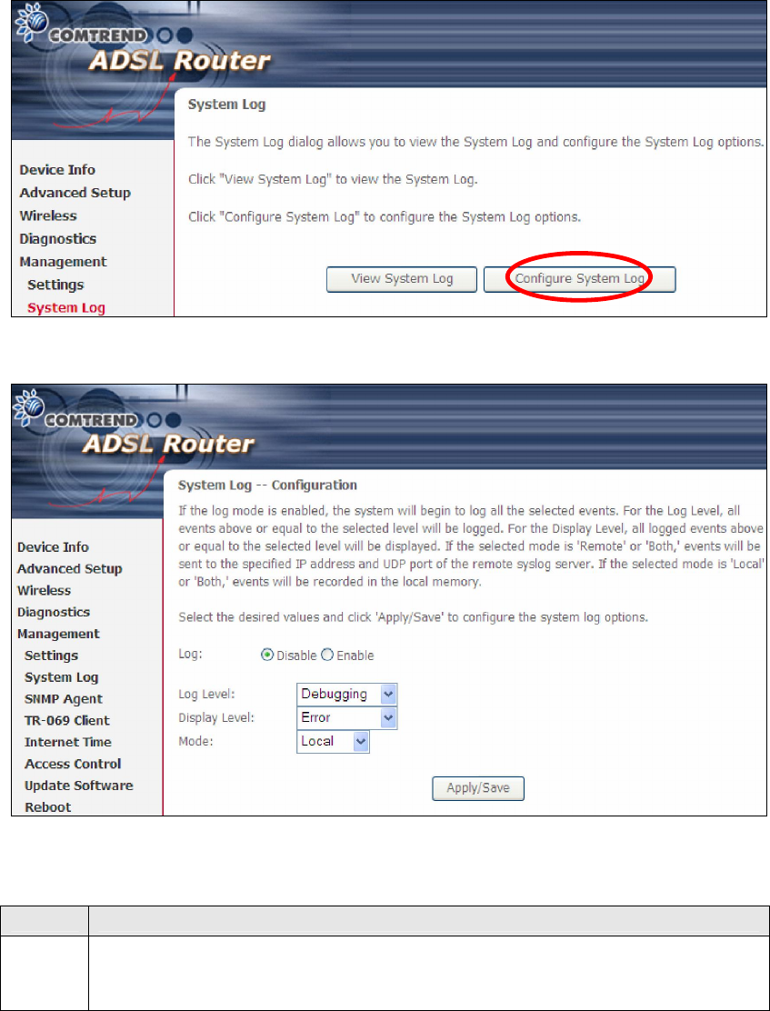
8.2 System Log
This function allows a system log to be kept and viewed upon request.
Follow the steps below to configure, enable, and view the system log.
STEP 1: Click Configure System Log, as shown below (circled in Red).
STEP 2: Select desired options and click Apply/Save.
Consult the table below for detailed descriptions of each system log option.
Option
Description
Log Indicates whether the system is currently recording events. The user
can enable or disable event logging. By default, it is disabled. To
enable it, select the Enable radio button and then click Apply/Save.

128
Option
Description
Log
Level
Allows you to configure the event level and filter out unwanted events
below this level. The events ranging from the highest critical level
“Emergency” down to this configured level will be recorded to the log
buffer on the AR-5389 SDRAM. When the log buffer is full, the newer
event will wrap up to the top of the log buffer and overwrite the old event.
By default, the log level is “Debugging”, which is the lowest critical level.
The log levels are defined as follows:
Emergency = system is unusable
Alert = action must be taken immediately
Critical = critical conditions
Error = Error conditions
Warning = normal but significant condition
Notice= normal but insignificant condition
Informational= provides information for reference
Debugging = debug-level messages
Emergency is the most serious event level, whereas Debugging is the
least important. For instance, if the log level is set to Debugging, all the
events from the lowest Debugging level to the most critical level
Emergency level will be recorded. If the log level is set to Error, only
Error and the level above will be logged.
Display
Level
Allows the user to select the logged events and displays on the View
System Log window for events of this level and above to the highest
Emergency level.
Mode Allows you to specify whether events should be stored in the local
memory, or be sent to a remote system log server, or both
simultaneously. If remote mode is selected, view system log will not be
able to display events saved in the remote system log server.
When either Remote mode or Both mode is configured, the WEB UI will
prompt the user to enter the Server IP address and Server UDP port.
STEP 3: Click View System Log. The results are displayed as follows.
129
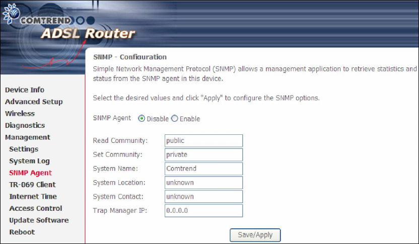
8.3 SNMP Agent
Simple Network Management Protocol (SNMP) allows a management application to
retrieve statistics and status from the SNMP agent in this device. Select the
Enable radio button, configure options, and click Save/Apply to activate SNMP.
130
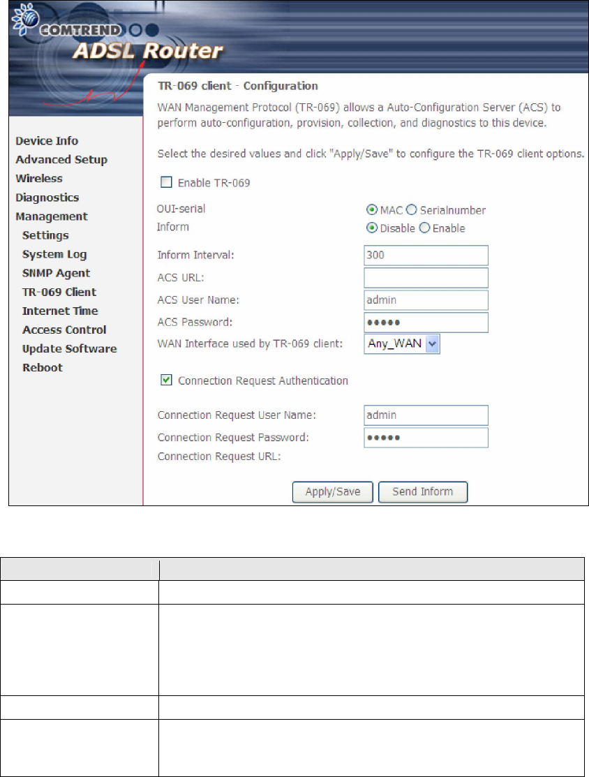
8.4 TR-069 Client
WAN Management Protocol (TR-069) allows an Auto-Configuration Server (ACS) to
perform auto-configuration, provision, collection, and diagnostics to this device.
Select desired values and click Apply/Save to configure TR-069 client options.
The table below is provided for ease of reference.
Option Description
Enable TR-069 Tick the checkbox to enable.
OUI-serial The serial number used to identify the CPE when making a
connection to the ACS using the CPE WAN Management
Protocol. Select MAC to use the router’s MAC address as
serial number to authenticate with ACS or select serial
number to use router’s serial number.
Inform Disable/Enable TR-069 client on the CPE.
Inform Interval The duration in seconds of the interval for which the CPE
MUST attempt to connect with the ACS and call the Inform
method.

131
Option Description
ACS URL URL for the CPE to connect to the ACS using the CPE WAN
Management Protocol. This parameter MUST be in the form
of a valid HTTP or HTTPS URL. An HTTPS URL indicates that
the ACS supports SSL. The “host” portion of this URL is
used by the CPE for validating the certificate from the ACS
when using certificate-based authentication.
ACS User Name Username used to authenticate the CPE when making a
connection to the ACS using the CPE WAN Management
Protocol. This username is used only for HTTP-based
authentication of the CPE.
ACS Password Password used to authenticate the CPE when making a
connection to the ACS using the CPE WAN Management
Protocol. This password is used only for HTTP-based
authentication of the CPE.
WAN Interface used
by TR-069 client
Choose Any_WAN, LAN, Loopback or a configured
connection.
Connection Request
Authorization Tick the checkbox to enable.
User Name Username used to authenticate an ACS making a
Connection Request to the CPE.
Password Password used to authenticate an ACS making a
Connection Request to the CPE.
URL IP address and port the ACS uses to connect to AR-5389.
The Send Inform button forces the CPE to establish an immediate connection to
the ACS.
132
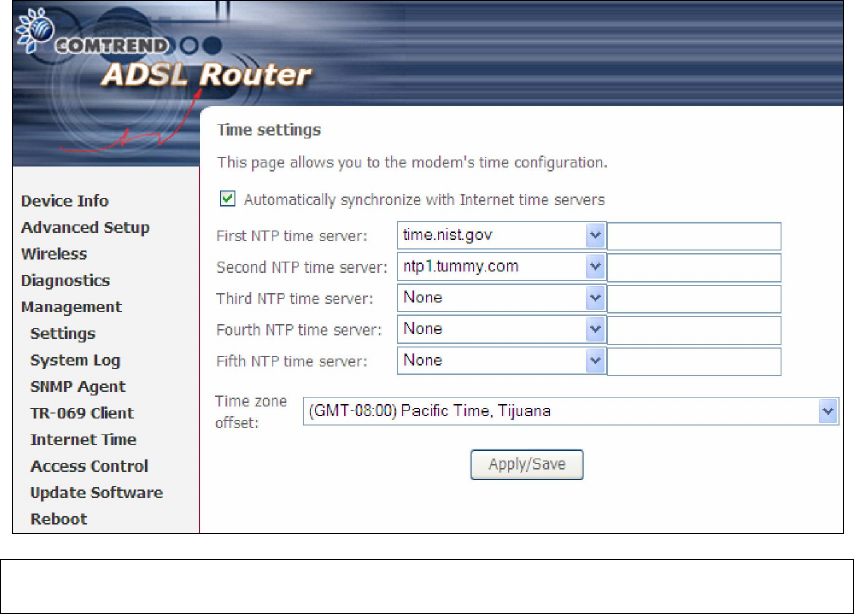
8.5 Internet Time
This option automatically synchronizes the router time with Internet timeservers.
To enable time synchronization, tick the corresponding checkbox , choose your
preferred time server(s), select the correct time zone offset, and click Save/Apply.
NOTE: In addition, this menu item is not displayed when in Bridge mode since
the router would not be able to connect to the NTP timeserver.
133
8.6 Access Control
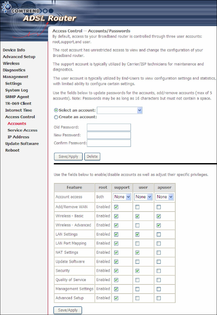
8.6.1 Accounts/Passwords
This screen is used to configure the user account access passwords for the device.
Access to the AR-5389 is controlled through the following user accounts:
root - unrestricted access to change and view the configuration.
support - typically utilized by Carrier/ISP technicians for maintenance and
diagnostics.
user - can view configuration settings & statistics and update firmware.
apuser - can configure wireless settings
Use the fields below to change password settings and privileges. Click Save/Apply
to continue.
134
NOTE: Passwords can be up to 16 characters in length.
135
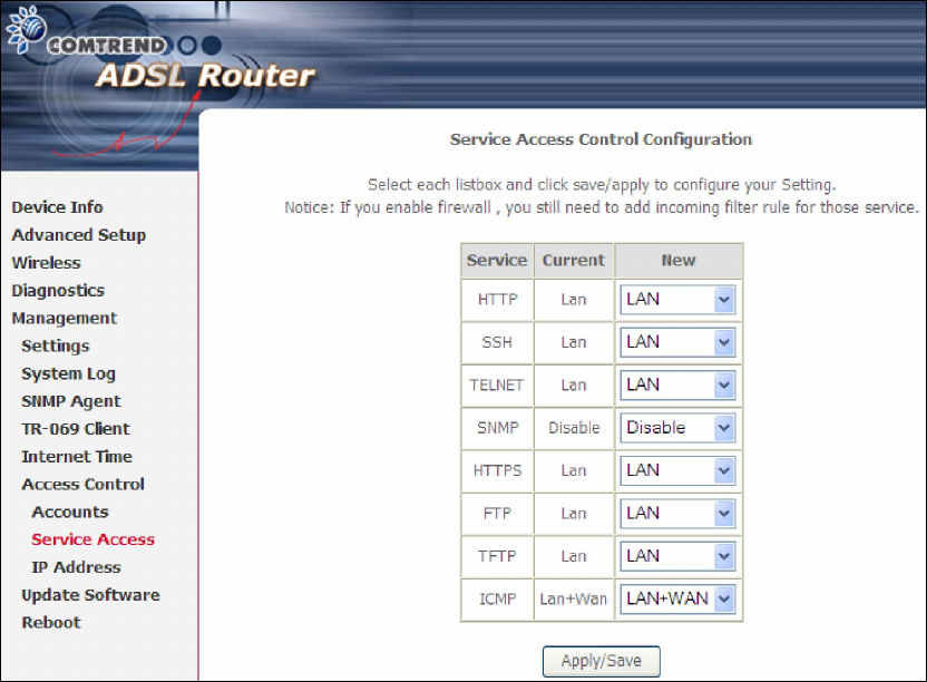
8.6.2 Service Access
The Services option limits or opens the access services over the LAN or WAN.
These access services available are: FTP, HTTP, ICMP, SNMP, TELNET and TFTP.
Enable a service by selecting its dropdown listbox. Click SAVE/APPLY to activate.
136
8.6.3 IP Address
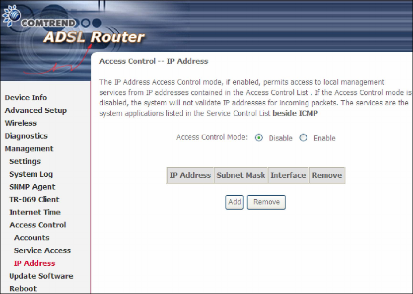
The IP Address Access Control mode, if enabled, permits access to local
management services from IP addresses contained in the Access Control List. If the
Access Control mode is disabled, the system will not validate IP addresses for
incoming packets. The services are the system applications listed in the Service
Control List beside ICMP.
Click the Add button to display the following.
137
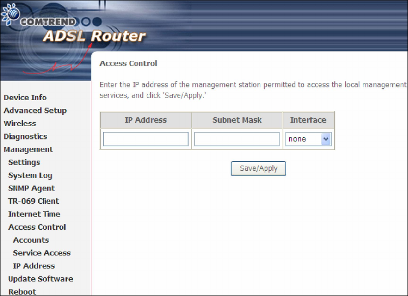
Configure the address and subnet of the management station permitted to access
the local management services, and click Save/Apply.
IP Address – IP address of the management station.
Subnet Mask – Subnet address for the management station.
Interface – Access permission for the specified address, allowing the address to
access the local management service from none/lan/wan/lan&wan interfaces.
138
8.7 Update Software
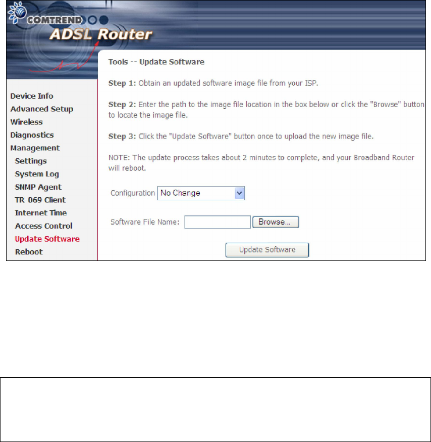
This option allows for firmware upgrades from a locally stored file.
Configuration: Select for the three options available.
STEP 1: Obtain an updated software image file from your ISP.
STEP 2: Enter the path and filename of the firmware image file in the Software
File Name field or click the Browse button to locate the image file.
STEP 3: Click the Update Software button once to upload and install the file.
NOTE: The update process will take about 2 minutes to complete. The device
will reboot and the browser window will refresh to the default screen upon
successful installation. It is recommended that you compare the
Software Version on the Chapter 4 Device Information screen with the
firmware version installed, to confirm the installation was successful.
139
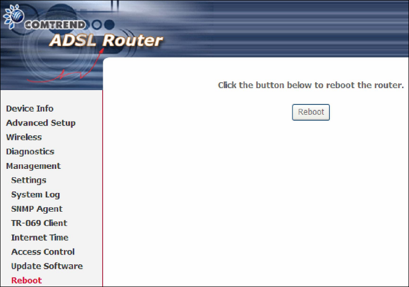
8.8 Reboot
To save the current configuration and reboot the router, click Save/Reboot.
NOTE: You may need to close the browser window and wait for 2 minutes before
reopening it. It may also be necessary, to reset your PC IP configuration.