Contents
- 1. AR-5389_user manual-1
- 2. AR-5389_user manual-2
- 3. AR-5389_user manual-3
- 4. AR-5389_user manual-4
AR-5389_user manual-4

140
Appendix A - Firewall
STATEFUL PACKET INSPECTION
Refers to an architecture, where the firewall keeps track of packets on each
connection traversing all its interfaces and makes sure they are valid. This is in
contrast to static packet filtering which only examines a packet based on the
information in the packet header.
DENIAL OF SERVICE ATTACK
Is an incident in which a user or organization is deprived of the services of a
resource they would normally expect to have. Various DoS attacks the device can
withstand are ARP Attack, Ping Attack, Ping of Death, Land, SYN Attack, Smurf
Attack, and Tear Drop.
TCP/IP/PORT/INTERFACE FILTER
These rules help in the filtering of traffic at the Network layer (i.e. Layer 3).
When a Routing interface is created, Enable Firewall must be checked.
Navigate to Advanced Setup Security IP Filtering.
OUTGOING IP FILTER
Helps in setting rules to DROP packets from the LAN interface. By default, if the
Firewall is Enabled, all IP traffic from the LAN is allowed. By setting up one or more
filters, specific packet types coming from the LAN can be dropped.
Example 1: Filter Name : Out_Filter1
Protocol : TCP
Source IP address : 192.168.1.45
Source Subnet Mask : 255.255.255.0
Source Port : 80
Dest. IP Address : NA
Dest. Subnet Mask : NA
Dest. Port : NA
This filter will Drop all TCP packets coming from the LAN with IP
Address/Subnet Mask of 192.168.1.45/24 having a source port of 80
irrespective of the destination. All other packets will be Accepted.
Example 2: Filter Name : Out_Filter2
Protocol : UDP
Source IP Address : 192.168.1.45
Source Subnet Mask : 255.255.255.0
Source Port : 5060:6060
Dest. IP Address : 172.16.13.4
Dest. Subnet Mask : 255.255.255.0
Dest. Port : 6060:7070
This filter will drop all UDP packets coming from the LAN with IP Address /
Subnet Mask of 192.168.1.45/24 and a source port range of 5060 to 6060,
destined to 172.16.13.4/24 and a destination port range of 6060 to 7070.
INCOMING IP FILTER
Helps in setting rules to Allow or Deny packets from the WAN interface. By default,
all incoming IP traffic from the WAN is Blocked, if the Firewall is Enabled. By setting
up one or more filters, specific packet types coming from the WAN can be Accepted.

141
Example 1: Filter Name : In_Filter1
Protocol : TCP
Policy : Allow
Source IP Address : 210.168.219.45
Source Subnet Mask : 255.255.0.0
Source Port : 80
Dest. IP Address : NA
Dest. Subnet Mask : NA
Dest. Port : NA
Selected WAN interface : br0
This filter will ACCEPT all TCP packets coming from WAN interface “br0” with IP
Address/Subnet Mask 210.168.219.45/16 with a source port of 80, irrespective
of the destination. All other incoming packets on this interface are DROPPED.
Example 2: Filter Name : In_Filter2
Protocol : UDP
Policy : Allow
Source IP Address : 210.168.219.45
Source Subnet Mask : 255.255.0.0
Source Port : 5060:6060
Dest. IP Address : 192.168.1.45
Dest. Sub. Mask : 255.255.255.0
Dest. Port : 6060:7070
Selected WAN interface : br0
This rule will ACCEPT all UDP packets coming from WAN interface “br0” with IP
Address/Subnet Mask 210.168.219.45/16 and a source port in the range of
5060 to 6060, destined to 192.168.1.45/24 and a destination port in the range
of 6060 to 7070. All other incoming packets on this interface are DROPPED.
MAC LAYER FILTER
These rules help in the filtering of Layer 2 traffic. MAC Filtering is only effective in
Bridge mode. After a Bridge mode connection is created, navigate to Advanced
Setup Security MAC Filtering in the WUI.
Example 1: Global Policy : Forwarded
Protocol Type : PPPoE
Dest. MAC Address : 00:12:34:56:78:90
Source MAC Address : NA
Src. Interface : eth1
Dest. Interface : eth2
Addition of this rule drops all PPPoE frames going from eth1 to eth2 with a
Destination MAC Address of 00:12:34:56:78:90 irrespective of its Source MAC
Address. All other frames on this interface are forwarded.
Example 2: Global Policy : Blocked
Protocol Type : PPPoE
Dest. MAC Address : 00:12:34:56:78:90
Source MAC Address : 00:34:12:78:90:56
Src. Interface : eth1
Dest. Interface : eth2
Addition of this rule forwards all PPPoE frames going from eth1 to eth2 with a
Destination MAC Address of 00:12:34:56:78 and Source MAC Address of
00:34:12:78:90:56. All other frames on this interface are dropped.
142
Appendix B - Specifications
Hardware Interface
RJ-11 X 1 for ADSL
RJ-45 X 4 for LAN (10/100 Base-T auto-sense)
WPS Button X 1
Wi-Fi On/Off Button X 1
Power Switch X 1
Wi-Fi Antenna X 1
WAN Interface
Downstream up to 8M for ADSL, 24 Mbps for ADSL2+; Upstream up to
1Mbps,for ANNEX M Upstream up to 2.4Mbps
ANSI T1.413 issue 2, ITU-T G.992.2 Annex A (G.lite), ITU-T G.992.3 Annex A,
L, M (ADSL2), TU-T G.992.5 Annex A, M (ADSL2+), ITU-T G 994.1, ITU-T
G.997.1, ETSI ETR-328
LAN Interface
Standard IEEE 802.3, IEEE 802.3u
Wireless Interface
IEEE802.11b/g/n
64, 128-bit Wired Equivalent Privacy (WEP) Data Encryption
11 Channels (US, Canada)/ 13 Channels (Europe)/ 14 Channels (Japan)
WPA/WPA2 Yes
Management
SNMP V2C
Remote upgrade
TFTP/FTP upgrade
Support TR069
Telnet remote access support
Support Web based configuration
Support for backup & restore configuration to/from PC
Support TR-64 for LAN management
Networking Protocols
ARFC 2684 IP Bridging
RFC 2684 IP Routing
RFC 2516, PPPoE (Point over Ethernet) over ATM
RFC 2364 PPPoA
Support 8 PVCs
QoS based on PVC
Routing: RIP v1, RIP v2
Support Static Routing
NAT & PAT (RFC 1631)
DMZ support
NAT with Application Layer Gateway
IP Routing: TCP, UDP, ICMP, ARP
143
DHCP Client/Server for IP management
DHCP Relay
IP multicasting IGMP v1/v2
Pass through/open/redirection and port mapping
The Range of private IP support 192.168.1.2 to 192.168.1.254
QoS mechanism support for mapping of PVC with different traffic classes
HTTP (web based) for firmware upgrade & configuration
IP filtering & raw filtering
IGMP Snooping support
IEEE 802.1D Transparent Bridging
DNS Relay
Security Functions
PAP, CHAP, TCP/IP/Port filtering rules
Port triggering/Forwarding,
Packet and MAC address filtering, Access control, SSH access
QoS
Port-based QoS,
802.1 bit marking
Firewall/Filtering
Stateful Inspection Firewall
Stateless Packet Filter
Denial of Service (DOS): ARP attacks, Ping attacks, Ping of Death, LAND,SYNC,
Smurf, Unreachable, Teardrop
TCP/IP/Port/interface filtering rules Support both incoming and outgoing
filtering
NAT/NAPT
Support Port Triggering and Port forwarding
Symmetric port-overloading NAT, Full-Cone NAT
Dynamic NAPT (NAPT N-to-1)
Support DMZ host
Virtual Server
VPN Passthrough (PPTP, L2TP, IPSec)
Application Passthrough
PPTP, L2TP, IPSec, VoIP, Yahoo messenger, ICQ, RealPlayer, NetMeeting, MSN, X-box,
etc.
Power Supply ................................................Input: 100 - 240 Vac
Output: 12 Vdc / 0.5 A
Environment Condition
Operating temperature............................0 ~ 50 degrees Celsius
Non-operating temperature………………………..-20 ~ 70 degrees Celsius
Humidity…………………….10 ~ 90% (non-condensing, standard operating)
Humidity……………………………….5 ~ 95% (non-condensing, non-operating)
Dimensions .....................................143 mm (W) x 35 mm (H) x 120 mm (D)

144
Certifications................................... CE, FCC
Kit Weight
(1*AR-5389, 1*RJ11 cable, 1*RJ45 cable, 1*power adapter, 1*CD-ROM)
NOTE: Specifications are subject to change without notice

145
Appendix C - SSH Client
Unlike Microsoft Windows, Linux OS has a ssh client included. For Windows users,
there is a public domain one called “putty” that can be downloaded from here:
http://www.chiark.greenend.org.uk/~sgtatham/putty/download.html
To access the ssh client you must first enable SSH access for the LAN or WAN from
the Management Access Control Services menu in the web user interface.
To access the router using the Linux ssh client
For LAN access, type: ssh -l admin 192.168.1.1
For WAN access, type: ssh -l support WAN IP address
To access the router using the Windows “putty” ssh client
For LAN access, type: putty -ssh -l admin 192.168.1.1
For WAN access, type: putty -ssh -l support WAN IP address
NOTE: The WAN IP address can be found on the Device Info WAN screen
146
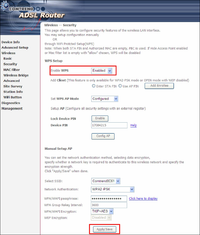
Appendix D - WPS OPERATION
This Section shows the basic AP WPS Operation procedure.
D1 Add Enrollee with Pin Method
1) Select Enabled from the Enable WPS dropdown menu.
2) Click the Apply/Save button at the bottom of the screen.
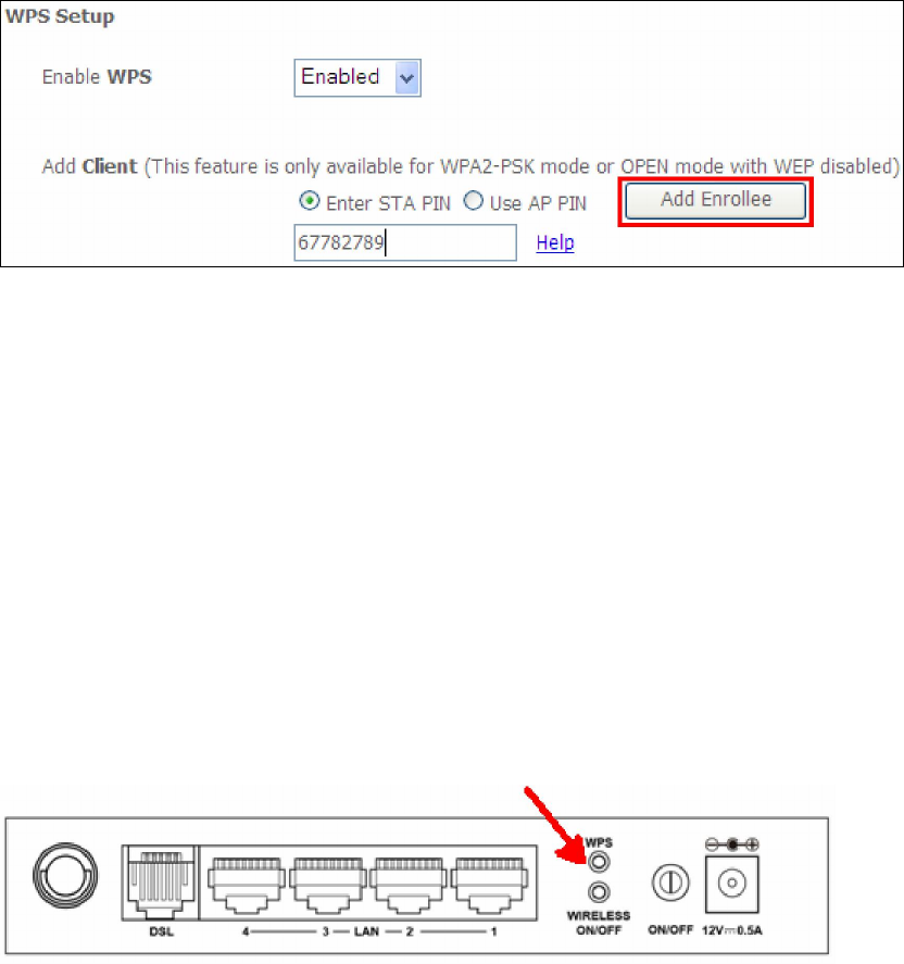
3) When the screen refreshes select the Radio button “Enter STA Pin”
4) Input Pin from Enrollee Station (67782789 in this example)
5) Click “Add Enrollee”
147
4) Operate Station to start WPS Adding Enrollee.
D2 Add Enrollee with PBC Method
1) Press the WPS button at back of the device to activate WPS PBC operation.
2) Operate Station (your dongle for example) to start WPS Adding Enrollee.
148
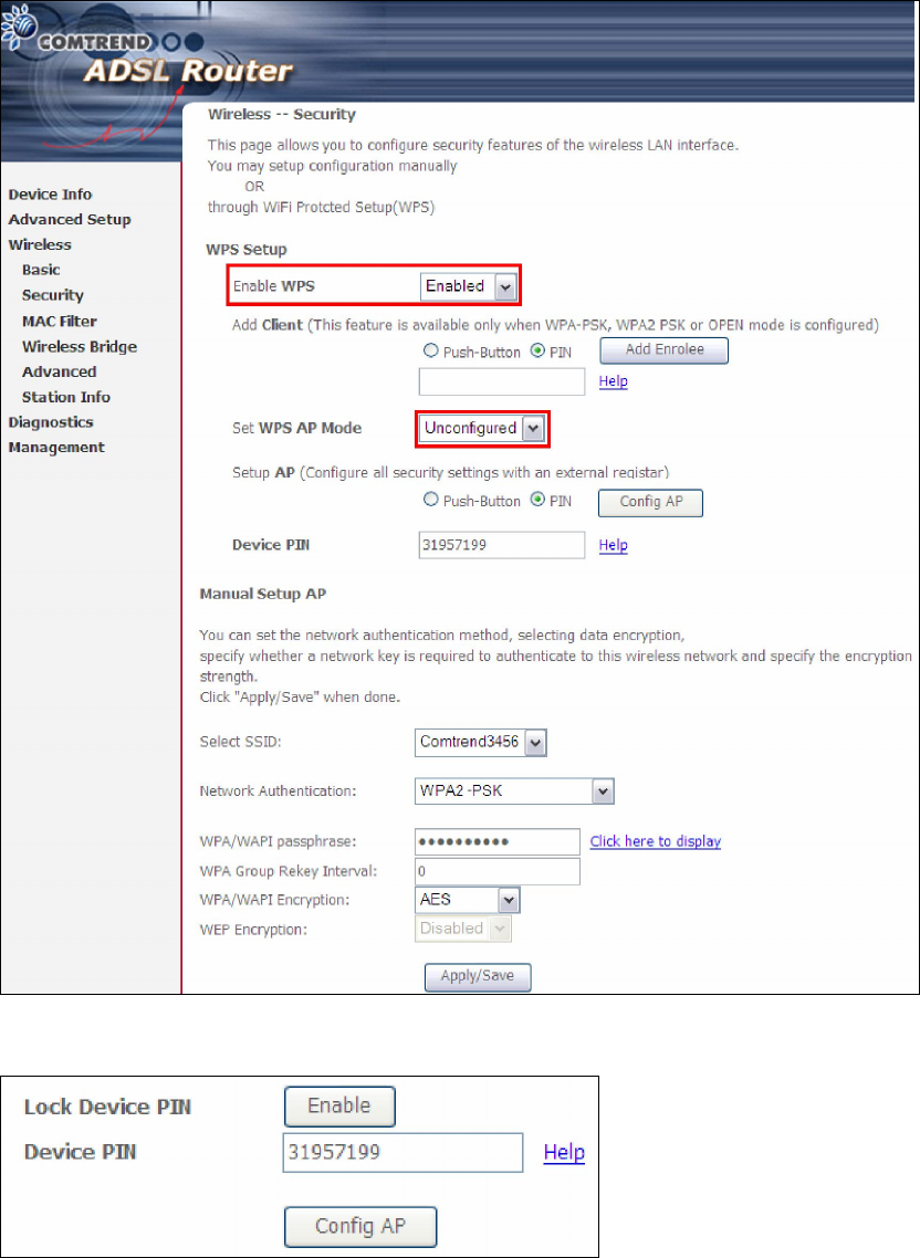
D3 Configure AP
1) Select Enabled from the Enable WPS dropdown menu.
2) Select Unconfigured from the Set WPS AP Mode dropdown menu.
3) Click the Apply/Save button at the bottom of the screen.
The following page will show these additional items.
Lock Device PIN
When enabled, device PIN is locked and cannot be used for WPS operation.
149
4) Read the Device Pin (31957199 in this example) and input to External
Registrar(ER – your dongle for example) when ER asks Device Pin ER could be wired
(for example Windows Vista) or wireless (Intel Station).
5) Do Web Page refresh after ER complete AP Configuration to check the new
parameters setting.
150
Appendix E - Connection Setup
Creating a WAN connection is a two-stage process.
1 - Setup a Layer 2 Interface (ATM, PTM or Ethernet).
2 - Add a WAN connection to the Layer 2 Interface.
The following sections describe each stage in turn.
E1 ~ Layer 2 Interfaces
Layer2 interface supports VLAN Mux modes, which allow for multiple connections
over a single interface. PPPoE, IPoE, and Bridge are supported while PPPoA and IPoA
connections are not.
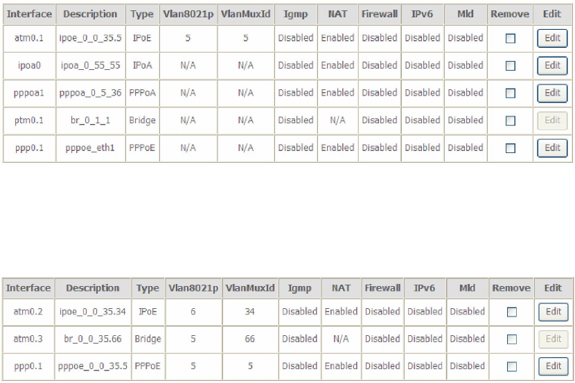
The figure below shows multiple connections over a single VLAN Mux interface.
VLAN MUX MODE
This mode uses VLAN tags to allow for multiple connections over a single interface.
PPPoE, IPoE, and Bridge are supported while PPPoA and IPoA connections are not.
The figure below shows multiple connections over a single VLAN Mux interface.

151
E1.1 ATM Interfaces
Follow these procedures to configure an ATM interface.
NOTE: The AR-5389 supports up to 16 ATM interfaces.
STEP 1: Go to Advanced Setup Layer2 Interface ATM Interface.
This table is provided here for ease of reference.
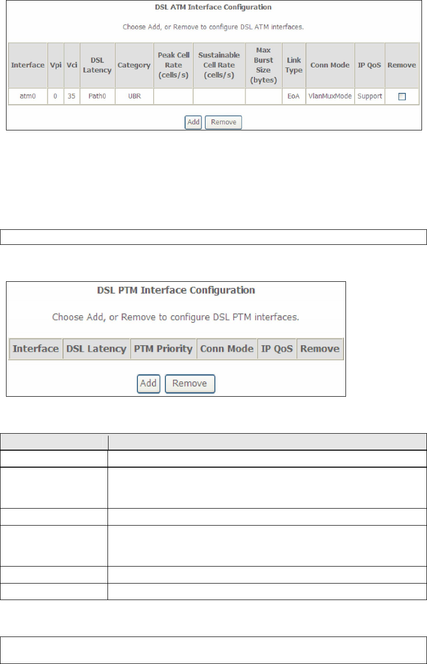
Heading Description
Interface WAN interface name.
VPI ATM VPI (0-255)
VCI ATM VCI (32-65535)
DSL Latency {Path0} port ID = 0
{Path1} port ID = 1
{Path0&1} port ID = 4
Category ATM service category
Peak Cell Rate Maximum allowed traffic rate for the ATM PCR service
connection
Sustainable Cell
Rate
The average allowable, long-term cell transfer rate on the VBR
service connection
Max Burst Size The maximum allowable burst size of cells that can be
transmitted contiguously on the VBR service connection
Link Type Choose EoA (for PPPoE, IPoE, and Bridge), PPPoA, or IPoA.
Connection Mode Default Mode – Single service over one connection
Vlan Mux Mode – Multiple Vlan service over one connection
IP QoS Quality of Service (IP QoS) status
Remove Select items for removal
STEP 2: Click Add to proceed to the next screen.
NOTE: To add WAN connections to one interface type, you must delete existing
connections from the other interface type using the remove button.
152
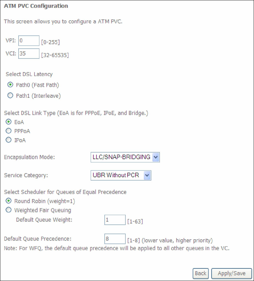
There are many settings here including: VPI/VCI, DSL Latency, DSL Link Type,
Encapsulation Mode, Service Category, Connection Mode and Quality of Service.
Here are the available encapsulations for each xDSL Link Type:
EoA- LLC/SNAP-BRIDGING, VC/MUX
PPPoA- VC/MUX, LLC/ENCAPSULATION
IPoA- LLC/SNAP-ROUTING, VC MUX
STEP 3: Click Apply/Save to confirm your choices.
On the next screen, check that the ATM interface is added to the list. For example,
an ATM interface on PVC 0/35 in Default Mode with an EoA Link type is shown below.
153
To add a WAN connection go to E2 ~ WAN Connections.
E1.2 PTM Interfaces
Follow these procedures to configure a PTM interface.
NOTE: The AR-5389 can support two PTM interfaces.
STEP 4: Go to Advanced Setup Layer2 Interface PTM Interface.
This table is provided here for ease of reference.
Heading Description
Interface WAN interface name.
DSL Latency {Path0} portID = 0
{Path1} port ID = 1
{Path0&1} port ID = 4
PTM Priority Normal or High Priority (Preemption).
Connection Mode Default Mode – Single service over one interface.
Vlan Mux Mode – Multiple Vlan services over one interface.
MSC Mode – Multiple Services over one interface.
QoS Quality of Service (QoS) status.
Remove Select interfaces to remove.
STEP 5: Click Add to proceed to the next screen.
NOTE: To add WAN connections to one interface type, you must delete existing
connections from the other interface type using the remove button.
154
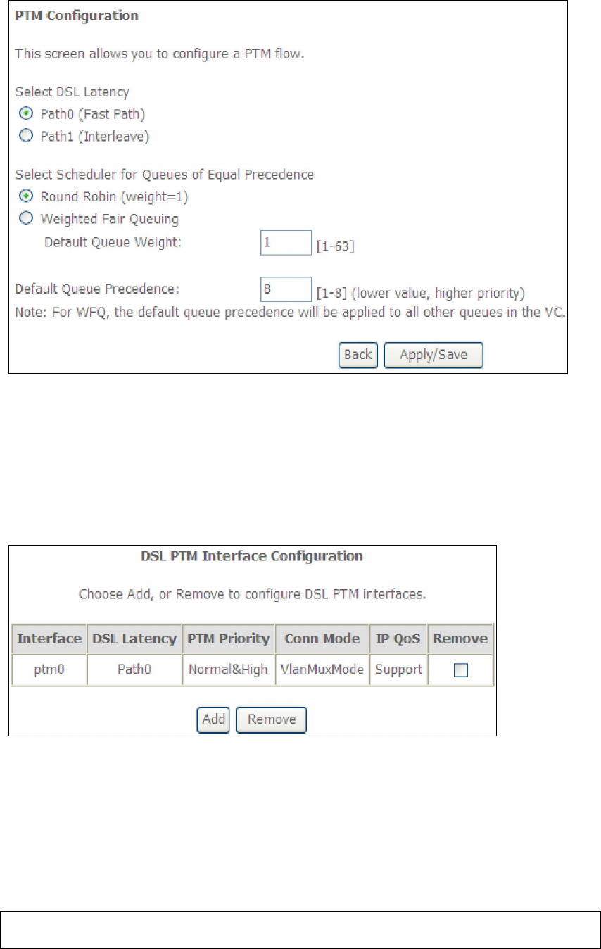
There are many settings that can be configured here including:
DSL Latency, PTM Priority, Connection Mode and Quality of Service.
STEP 6: Click Apply/Save to confirm your choices.
On the next screen, check that the PTM interface is added to the list.
For example, an PTM interface in Default Mode is shown below.
To add a WAN connection go to E2 ~ WAN Connections.
E1.3 Ethernet WAN Interface
Some models of the AR-5389 support a single Ethernet WAN interface over the ETH
WAN port. Follow these procedures to configure an Ethernet WAN interface.
NOTE: To add WAN connections to one interface type, you must delete existing
connections from the other interface type using the remove button.
155
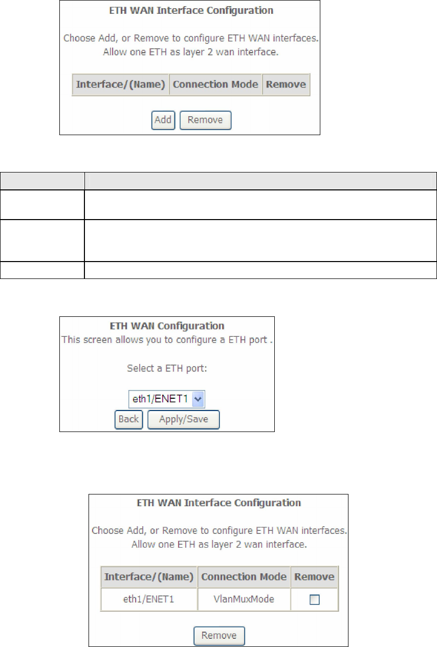
STEP 1: Go to Advanced Setup Layer2 Interface ETH Interface.
This table is provided here for ease of reference.
Heading Description
Interface/
(Name)
ETH WAN Interface
Connection
Mode
Default Mode – Single service over one connection
Vlan Mux Mode – Multiple Vlan service over one connection
MSC Mode – Multiple Service over one Connection
Remove Select the checkbox and click Remove to remove the connection.
STEP 2: Click Add to proceed to the next screen.
STEP 3: STEP 4: Click Apply/Save to confirm your choice.
The figure below shows an Ethernet WAN interface configured in VlanMuxMode.
To add a WAN connection go to Appendix E - Connection Setup.
156
E2 ~ WAN Connections
In Default Mode, the AR-5389 supports up to 16 connections.
To setup a WAN connection follow these instructions.
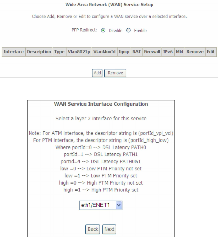
STEP 1: Go to the Advanced Setup WAN Service screen.
STEP 2: Click Add to create a WAN connection. The following screen will display.
STEP 3: Choose a layer 2 interface from the drop-down box and click Next.
The WAN Service Configuration screen will display as shown below.
157
NOTE: The WAN services shown here are those supported by the layer 2
interface you selected in the previous step. If you wish to change your
selection click the Back button and select a different layer 2 interface.
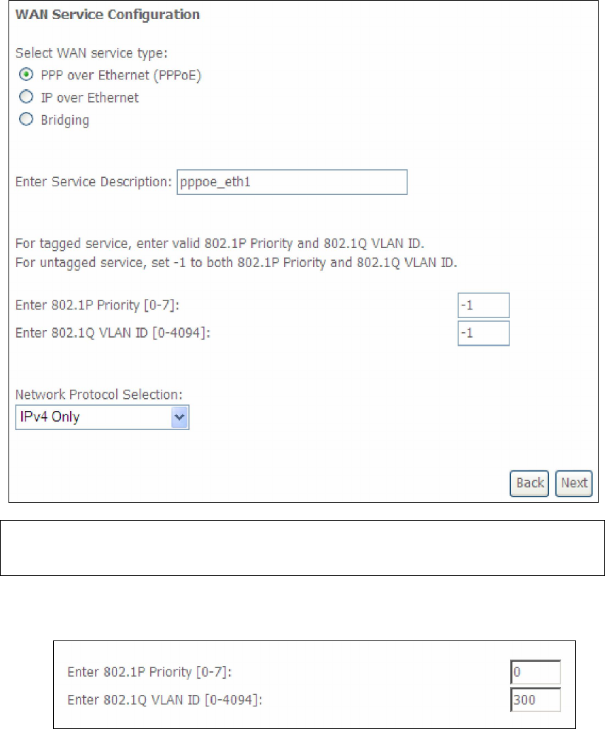
STEP 4: For VLAN Mux Connections, you must enter Priority & VLAN ID tags.
STEP 5: You will now follow the instructions specific to the WAN service type you
wish to establish. This list should help you locate the correct procedure:
(1) For PPP over ETHERNET (PPPoE), go to page 152.
(2) For IP over ETHERNET (IPoE), go to page 158.
(3) For Bridging, go to page 164.
(4) For PPP over ATM (PPPoA), go to page 166.
(5) For IP over ATM (IPoA), go to page 171.
The subsections that follow continue the WAN service setup procedure.
158
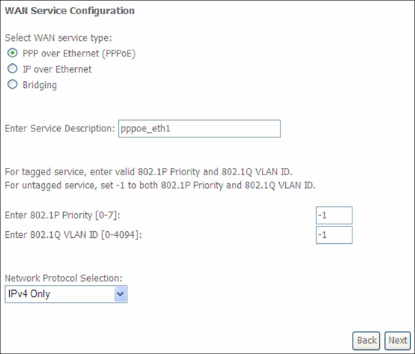
E2.1 PPP over ETHERNET (PPPoE)
STEP 1: Select the PPP over Ethernet radio button and click Next. You can also
enable IPv6 by ticking the checkbox at the bottom of this screen.
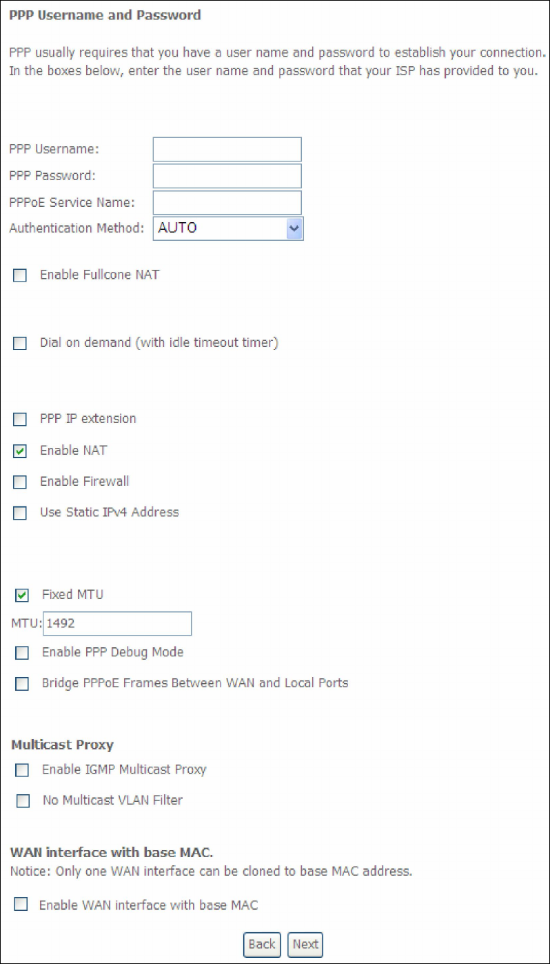
STEP 2: On the next screen, enter the PPP settings as provided by your ISP.
Click Next to continue or click Back to return to the previous step.
159
160
The settings shown above are described below.
PPP SETTINGS
The PPP Username, PPP password and the PPPoE Service Name entries are
dependent on the particular requirements of the ISP. The user name can be a
maximum of 256 characters and the password a maximum of 32 characters in
length. For Authentication Method, choose from AUTO, PAP, CHAP, and MSCHAP.
ENABLE FULLCONE NAT
This option becomes available when NAT is enabled. Known as one-to-one NAT, all
requests from the same internal IP address and port are mapped to the same
external IP address and port. An external host can send a packet to the internal host,
by sending a packet to the mapped external address.
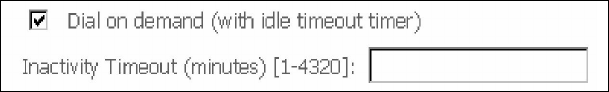
DIAL ON DEMAND
The AR-5389 can be configured to disconnect if there is no activity for a period of
time by selecting the Dial on demand checkbox . You must also enter an
inactivity timeout period in the range of 1 to 4320 minutes.
PPP IP EXTENSION
The PPP IP Extension is a special feature deployed by some service providers.
Unless your service provider specifically requires this setup, do not select it.
PPP IP Extension does the following:
Allows only one PC on the LAN.
Disables NAT and Firewall.
The device becomes the default gateway and DNS server to the PC
through DHCP using the LAN interface IP address.
The device extends the IP subnet at the remote service provider to the
LAN PC. i.e. the PC becomes a host belonging to the same IP subnet.
The device bridges the IP packets between WAN and LAN ports, unless
the packet is addressed to the device’s LAN IP address.
The public IP address assigned by the remote side using the PPP/IPCP
protocol is actually not used on the WAN PPP interface. Instead, it is
forwarded to the PC LAN interface through DHCP. Only one PC on the
LAN can be connected to the remote, since the DHCP server within the
device has only a single IP address to assign to a LAN device.
ENABLE NAT
If the LAN is configured with a private IP address, the user should select this
checkbox . The NAT submenu will appear in the Advanced Setup menu after reboot.
On the other hand, if a private IP address is not used on the LAN side (i.e. the LAN
side is using a public IP), this checkbox should not be selected to free up system
resources for better performance.
ENABLE FIREWALL
If this checkbox is selected, the Security submenu will be displayed on the
Advanced Setup menu after reboot. If firewall is not necessary, this checkbox
should not be selected to free up system resources for better performance.

161
USE STATIC IPv4 ADDRESS
Unless your service provider specially requires it, do not select this checkbox . If
selected, enter the static IP address in the IPv4 Address field.
Don’t forget to adjust the IP configuration to Static IP Mode as described in Section
3.2
MTU
Maximum Transmission Unit. The size (in bytes) of largest protocol data unit which
the layer can pass onwards. This value is 1500 for PPPoA.
ENABLE PPP DEBUG MODE
When this option is selected, the system will put more PPP connection information
into the system log. This is for debugging errors and not for normal usage.
BRIDGE PPPOE FRAMES BETWEEN WAN AND LOCAL PORTS
(This option is hidden when PPP IP Extension is enabled)
When Enabled, this creates local PPPoE connections to the WAN side. Enable this
option only if all LAN-side devices are running PPPoE clients, otherwise disable it.
The VR-3025u supports pass-through PPPoE sessions from the LAN side while
simultaneously running a PPPoE client from non-PPPoE LAN devices.
ENABLE IGMP MULTICAST PROXY
Tick the checkbox to enable Internet Group Membership Protocol (IGMP)
multicast. This protocol is used by IPv4 hosts to report their multicast group
memberships to any neighboring multicast routers.
NO MULTICAST VLAN FILTER
Tick the checkbox to Enable/Disable multicast VLAN filter.
Enable WAN interface with base MAC
Enable this option to use the router’s base MAC address as the MAC address for this
WAN interface.
STEP 3: Choose an interface to be the default gateway.
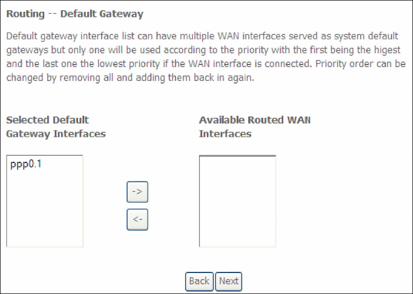
162
Click Next to continue or click Back to return to the previous step.
Select DNS Server Interface from available WAN interfaces OR enter static DNS
server IP addresses for the system. In ATM mode, if only a single PVC with IPoA or
static IPoE protocol is configured, Static DNS server IP addresses must be entered.
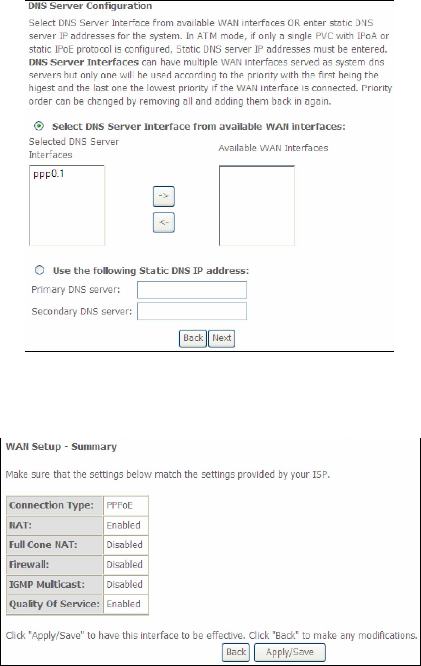
163
Click Next to continue or click Back to return to the previous step.
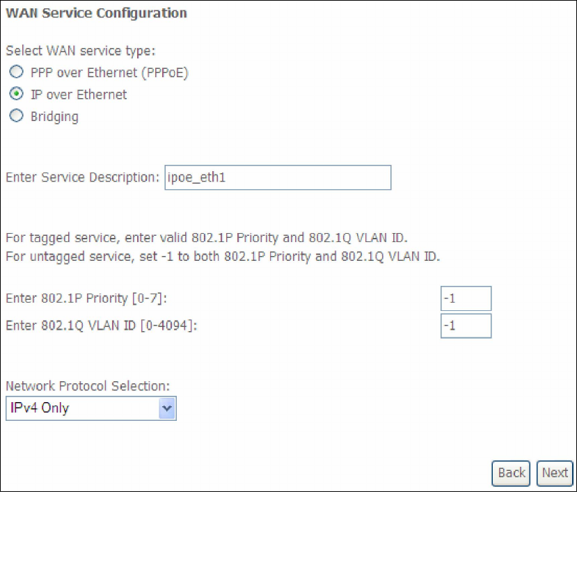
STEP 5: The WAN Setup - Summary screen shows a preview of the WAN service
you have configured. Check these settings and click Apply/Save if they
are correct, or click Back to modify them.
After clicking Apply/Save, the new service should appear on the main screen.
To activate it you must reboot. Go to Management Reboot and click Reboot.
164
E2.2 IP over ETHERNET (IPoE)
STEP 1: *Select the IP over Ethernet radio button and click Next.
*
For tagged service, enter valid 802.1P Priority and 802.1Q VLAN ID.
For untagged service, set -1 to both 802.1P Priority and 802.1Q VLAN ID.
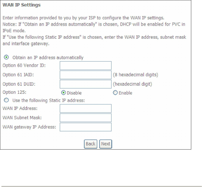
STEP 2: The WAN IP settings screen provides access to the DHCP server settings.
You can select the Obtain an IP address automatically radio button to
enable DHCP (use the DHCP Options only if necessary). However, if you
prefer, you can instead use the Static IP address method to assign WAN
IP address, Subnet Mask and Default Gateway manually.
165
NOTE: If IPv6 networking is enabled, an additional set of instructions, radio
buttons, and text entry boxes will appear at the bottom of the screen.
These configuration options are quite similar to those for IPv4 networks.
Click Next to continue or click Back to return to the previous step.
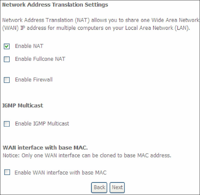
STEP 3: This screen provides access to NAT, Firewall and IGMP Multicast settings.
Enable each by selecting the appropriate checkbox . Click Next to
continue or click Back to return to the previous step.
166
ENABLE NAT
If the LAN is configured with a private IP address, the user should select this
checkbox . The NAT submenu will appear in the Advanced Setup menu after
reboot. On the other hand, if a private IP address is not used on the LAN side (i.e.
the LAN side is using a public IP), this checkbox should not be selected, so as to
free up system resources for improved performance.
ENABLE FULLCONE NAT
This option becomes available when NAT is enabled. Known as one-to-one NAT, all
requests from the same internal IP address and port are mapped to the same
external IP address and port. An external host can send a packet to the internal host,
by sending a packet to the mapped external address.
ENABLE FIREWALL
If this checkbox is selected, the Security submenu will be displayed on the
Advanced Setup menu after reboot. If firewall is not necessary, this checkbox
should not be selected so as to free up system resources for better performance.
ENABLE IGMP MULTICAST
Tick the checkbox to enable Internet Group Membership Protocol (IGMP)
multicast. IGMP is a protocol used by IPv4 hosts to report their multicast group
memberships to any neighboring multicast routers.
Enable WAN interface with base MAC
Enable this option to use the router’s base MAC address as the MAC address for this
WAN interface.
167
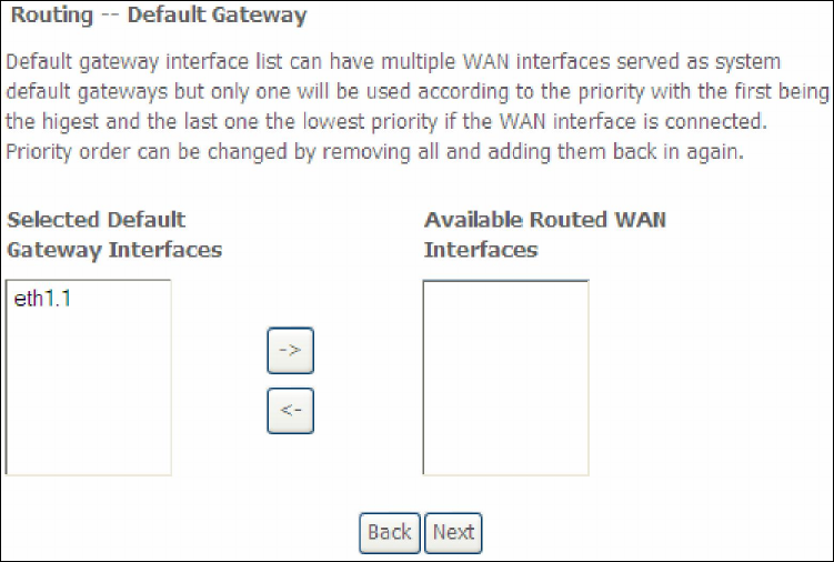
STEP 4: To choose an interface to be the default gateway.
Click Next to continue or click Back to return to the previous step.
STEP 5: Select DNS Server Interface from available WAN interfaces OR enter static
DNS server IP addresses for the system. In ATM mode, if only a single PVC with IPoA
or static IPoE protocol is configured, Static DNS server IP addresses must be
entered.
168
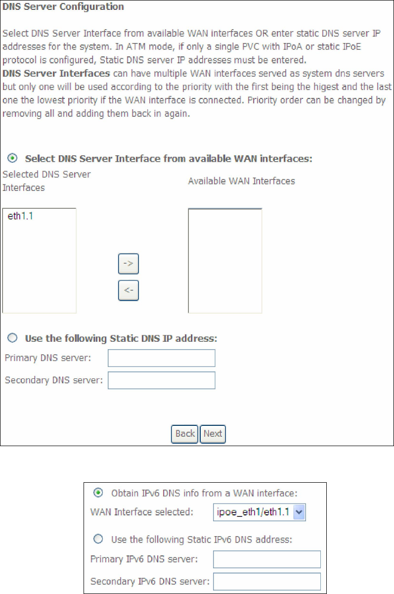
If IPv6 is enabled, an additional set of options will be shown.
IPv6: Select the configured WAN interface for IPv6 DNS server information OR
enter the static IPv6 DNS server Addresses.
Note that selecting a WAN interface for IPv6 DNS server will enable DHCPv6 Client
on that interface.
Click Next to continue or click Back to return to the previous step.
169
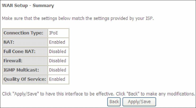
STEP 6: The WAN Setup - Summary screen shows a preview of the WAN service
you have configured. Check these settings and click Apply/Save if they
are correct, or click Back to modify them.
After clicking Apply/Save, the new service should appear on the main screen.
To activate it you must reboot. Go to Management Reboot and click Reboot.
170
E2.3 Bridging
NOTE: This connection type is not available on the Ethernet WAN interface.
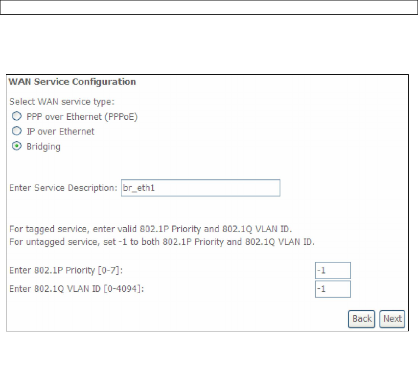
STEP 1: *Select the Bridging radio button and click Next.
*
For tagged service, enter valid 802.1P Priority and 802.1Q VLAN ID.
For untagged service, set -1 to both 802.1P Priority and 802.1Q VLAN ID.
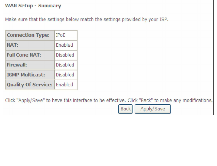
STEP 2: The WAN Setup - Summary screen shows a preview of the WAN service
you have configured. Check these settings and click Apply/Save if they
are correct, or click Back to return to the previous screen.
171
After clicking Apply/Save, the new service should appear on the main screen.
To activate it you must reboot. Go to Management Reboot and click Reboot.
NOTE: If this bridge connection is your only WAN service, the AR-5389 will be
inaccessible for remote management or technical support from the WAN.
172
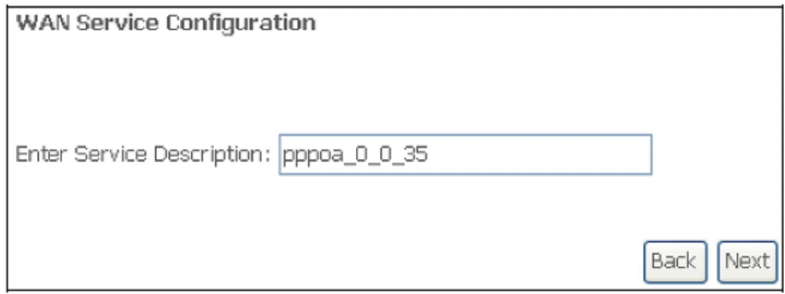
E2.4 PPP over ATM (PPPoA)
STEP 1: Click Next to continue.
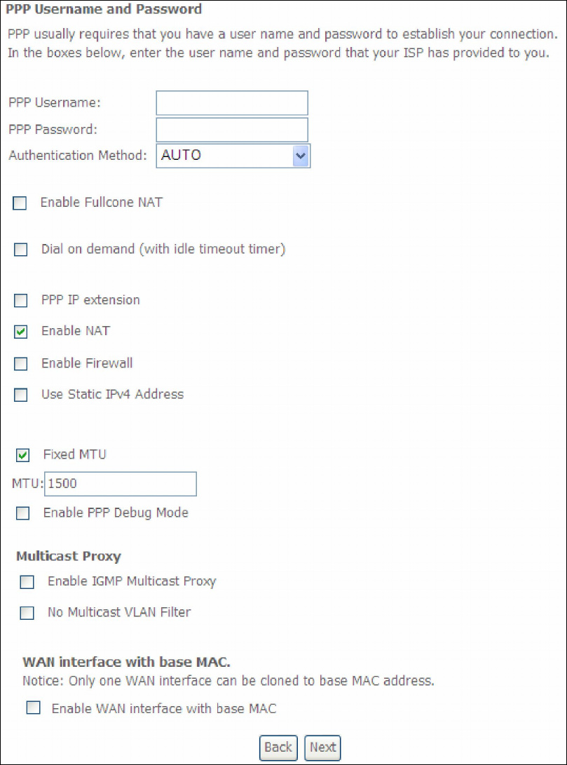
STEP 2: On the next screen, enter the PPP settings as provided by your ISP.
Click Next to continue or click Back to return to the previous step.
173
PPP SETTINGS
The PPP username and password are dependent on the requirements of the ISP.
The user name can be a maximum of 256 characters and the password a maximum
of 32 characters in length. (Authentication Method: AUTO, PAP, CHAP, or MSCHAP.)
ENABLE FULLCONE NAT
This option becomes available when NAT is enabled. Known as one-to-one NAT, all
requests from the same internal IP address and port are mapped to the same
external IP address and port. An external host can send a packet to the internal host,
by sending a packet to the mapped external address.
174
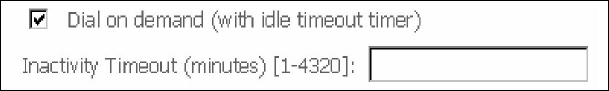
DIAL ON DEMAND
The AR-5389 can be configured to disconnect if there is no activity for a period of
time by selecting the Dial on demand checkbox . You must also enter an
inactivity timeout period in the range of 1 to 4320 minutes.
PPP IP EXTENSION
The PPP IP Extension is a special feature deployed by some service providers.
Unless your service provider specifically requires this setup, do not select it.
PPP IP Extension does the following:
Allows only one PC on the LAN.
Disables NAT and Firewall.
The device becomes the default gateway and DNS server to the PC
through DHCP using the LAN interface IP address.
The device extends the IP subnet at the remote service provider to the
LAN PC. i.e. the PC becomes a host belonging to the same IP subnet.
The device bridges the IP packets between WAN and LAN ports, unless
the packet is addressed to the device’s LAN IP address.
The public IP address assigned by the remote side using the PPP/IPCP
protocol is actually not used on the WAN PPP interface. Instead, it is
forwarded to the PC LAN interface through DHCP. Only one PC on the
LAN can be connected to the remote, since the DHCP server within the
device has only a single IP address to assign to a LAN device.
ENABLE NAT
If the LAN is configured with a private IP address, the user should select this
checkbox . The NAT submenu will appear in the Advanced Setup menu after reboot.
On the other hand, if a private IP address is not used on the LAN side (i.e. the LAN
side is using a public IP), this checkbox should not be selected to free up system
resources for better performance.
ENABLE FIREWALL
If this checkbox is selected, the Security submenu will be displayed on the
Advanced Setup menu after reboot. If firewall is not necessary, this checkbox
should not be selected to free up system resources for better performance.
USE STATIC IPv4 ADDRESS
Unless your service provider specially requires it, do not select this checkbox . If
selected, enter the static IP address in the IP Address field. Also, don’t forget to
adjust the IP configuration to Static IP Mode as described in Section 3.2.
Fixed MTU
Fixed Maximum Transmission Unit. The size (in bytes) of largest protocol data unit
which the layer can pass onwards. This value is 1500 for PPPoA.
ENABLE PPP DEBUG MODE
When this option is selected, the system will put more PPP connection information
into the system log. This is for debugging errors and not for normal usage.
175
ENABLE IGMP MULTICAST
Tick the checkbox to enable Internet Group Membership Protocol (IGMP)
multicast. IGMP is a protocol used by IPv4 hosts to report their multicast group
memberships to any neighboring multicast routers.
NO MULTICAST VLAN FILTER
Tick the checkbox to have the multicast packets bypass the VLAN filter.
Enable WAN interface with base MAC
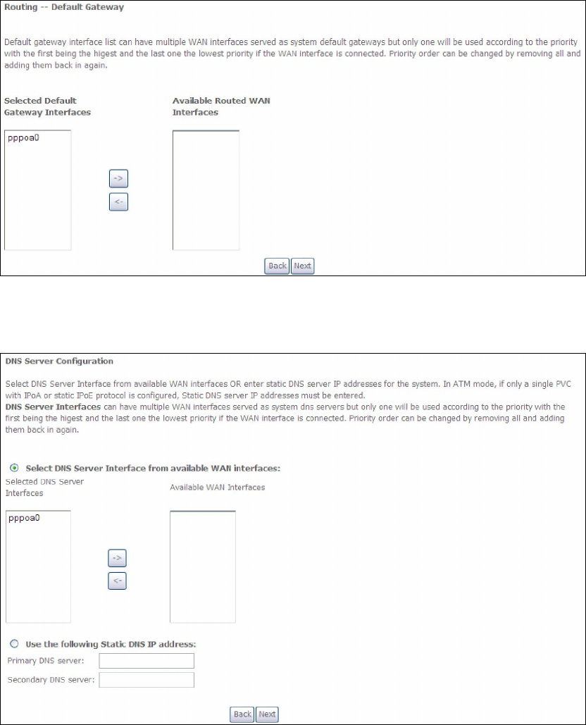
STEP 3: Choose an interface to be the default gateway.
Click Next to continue or click Back to return to the previous step.
STEP 4: Choose an interface to be the default gateway.
Click Next to continue or click Back to return to the previous step.
176
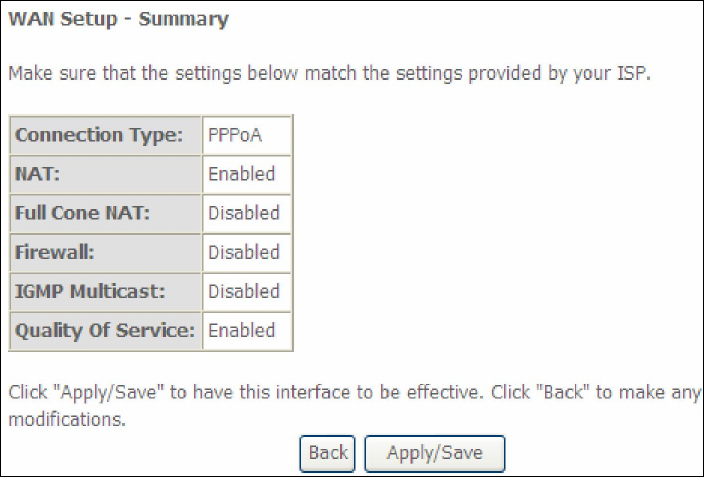
STEP 5: The WAN Setup - Summary screen shows a preview of the WAN service
you have configured. Check these settings and click Apply/Save if they
are correct, or click Back to modify them.
After clicking Apply/Save, the new service should appear on the main screen.
To activate it you must reboot. Go to Management Reboot and click Reboot.
177
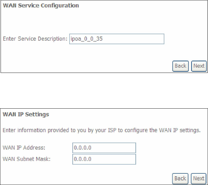
E2.5 IP over ATM (IPoA)
STEP 1: Click Next to continue.
STEP 2: Enter the WAN IP settings provided by your ISP. Click Next to continue.
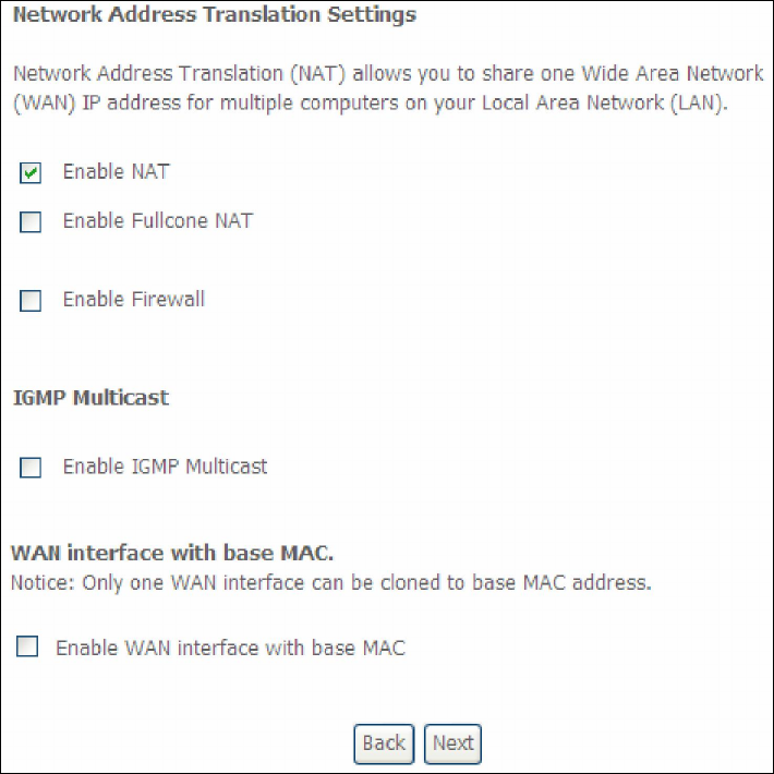
STEP 3: This screen provides access to NAT, Firewall and IGMP Multicast settings.
Enable each by selecting the appropriate checkbox . Click Next to
continue or click Back to return to the previous step.
178
ENABLE NAT
If the LAN is configured with a private IP address, the user should select this
checkbox . The NAT submenu will appear in the Advanced Setup menu after
reboot. On the other hand, if a private IP address is not used on the LAN side (i.e.
the LAN side is using a public IP), this checkbox should not be selected, so as to
free up system resources for improved performance.
ENABLE FULLCONE NAT
This option becomes available when NAT is enabled. Known as one-to-one NAT, all
requests from the same internal IP address and port are mapped to the same
external IP address and port. An external host can send a packet to the internal host
by sending a packet to the mapped external address.
ENABLE FIREWALL
If this checkbox is selected, the Security submenu will be displayed on the
Advanced Setup menu after reboot. If firewall is not necessary, this checkbox
should not be selected so as to free up system resources for better performance.
ENABLE IGMP MULTICAST
Tick the checkbox to enable Internet Group Membership Protocol (IGMP)
multicast. IGMP is a protocol used by IPv4 hosts to report their multicast group
memberships to any neighboring multicast routers.
Enable WAN interface with base MAC
Enable this option to use the router’s base MAC address as the MAC address for this
WAN interface.
179
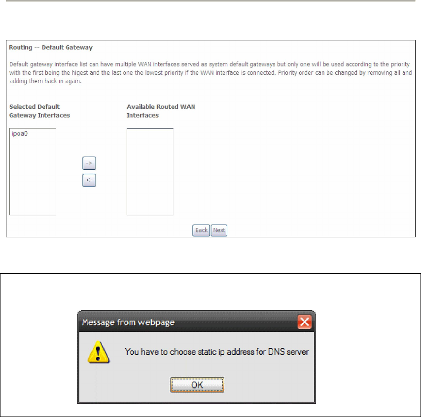
STEP 4: Choose an interface to be the default gateway.
Click Next to continue or click Back to return to the previous step.
NOTE: If the DHCP server is not enabled on another WAN interface then the
following notification will be shown before the next screen.
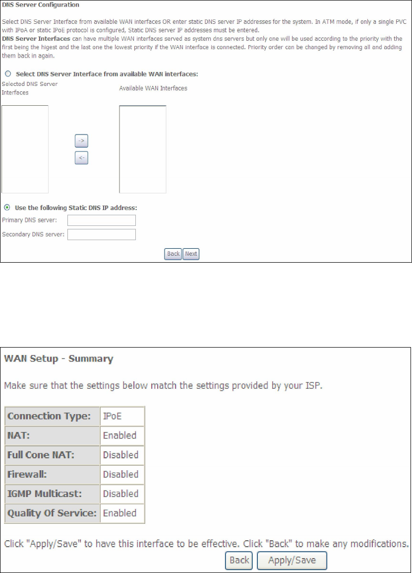
STEP 5: Choose an interface to be the default gateway.
180
Click Next to continue or click Back to return to the previous step.
STEP 6: The WAN Setup - Summary screen shows a preview of the WAN service
you have configured. Check these settings and click Apply/Save if they
are correct, or click Back to modify them.
After clicking Apply/Save, the new service should appear on the main screen.
To activate it you must reboot. Go to Management Reboot and click Reboot.

FCC INFORMATION
This equipment complies with CFR 47, Part 15.19 of the FCC rules. Operation of the equipment is subject to the following
conditions: (1) this device may not cause harmful interference, and (2) this device must accept any interference received; including
interference that may cause undesired operation.
THIS DEVICE MUST NOT BE CO-LOCATED OR OPERATING IN CONJUNCTION WITH ANY OTHER ANTENNA OR TRANSMITTER
NOTE: THE MANUFACTURER IS NOT RESPONSIBLE FOR ANY RADIO OR TV INTERFERENCE CAUSED BY
UNAUTHORIZED MODIFICATIONS TO THIS EQUIPMENT. SUCH MODIFICATIONS COULD VOID THE USER’S
AUTHORITY TO OPERATE THE EQUIPMENT.
Federal Communications Commission (FCC) Requirements, Part 15
This equipment has been tested and found to comply with the limits for a class B digital device, pursuant to part 15 of the FCC
Rules. These limits are designed to provide reasonable protection against harmful interference in a residential installation.
This equipment generates, uses and can radiate radio frequency energy and, if not installed and used in accordance with the
instructions, may cause harmful interference to radio communications. However, there is no guarantee that interference will not
occur in a particular installation. If this equipment does cause harmful interference to radio or television reception, which can be
determined by turning the equipment off and on, the user is encouraged to try to correct the interference by one or more of the
following measures:
---Reorient or relocate the receiving antenna.
---Increase the separation between the equipment and receiver.
---Connect the equipment into an outlet on a circuit different from that to which the receiver is connected.
---Consult the dealer or an experienced radio/TV technician for help.
REGULATORY INFORMATION / DISCLAIMERS
Installation and use of this Wireless LAN device must be in strict accordance with the instructions included in the user
documentation provided with the product. Any changes or modifications (including the antennas) made to this device that are not
expressly approved by the manufacturer may void the user’s authority to operate the equipment. The manufacturer is not
responsible for any radio or television interference caused by unauthorized modification of this device, or the substitution of the
connecting cables and equipment other than manufacturer specified. It is the responsibility of the user to correct any interference
caused by such unauthorized modification, substitution or attachment. Manufacturer and its authorized resellers or distributors will
assume no liability for any damage or violation of government
CAUTION: To maintain compliance with FCC’s RF exposure guidelines, this equipment should be installed and operated with
minimum distance 20cm between the radiator and your body. Use on the supplied antenna. Unauthorized antenna, modification, or
attachments could damage the transmitter and may violate FCC regulations.
MPE Statement (Safety Information)
Your device contains a low power transmitter. When device is transmitted it sends out Radio Frequency (RF) signal.
SAFETY INFORMATION
In order to maintain compliance with the FCC RF exposure guidelines, this equipment should be installed and operated with
minimum distance 20cm between the radiator and your body. Use only with supplied antenna. Unauthorized antenna, modification,
or attachments could damage the transmitter and may violate FCC regulations.