Contents
- 1. AR-5389_user manual-1
- 2. AR-5389_user manual-2
- 3. AR-5389_user manual-3
- 4. AR-5389_user manual-4
AR-5389_user manual-2
60
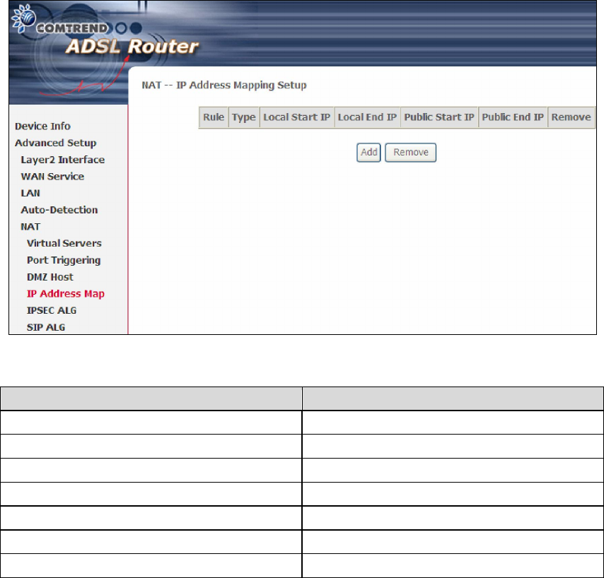
5.5.4 IP Address Map
Mapping Local IP (LAN IP) to some specified Public IP (WAN IP).
Consult the table below for field and header descriptions.
Field/Header Description
Rule The number of the rule
Type Mapping type from local to public.
Local Start IP The beginning of the local IP
Local End IP The ending of the local IP
Public Start IP The beginning of the public IP
Public End IP The ending of the public IP
Remove Remove this rule
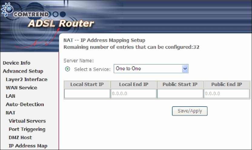
Click the Add button to display the following screen.
61
Select a Service, then click the Save/Apply button.
One to One: mapping one local IP to a specific public IP
Many to One: mapping a range of local IP to a specific public IP
Many to Many(Overload): mapping a range of local IP to a different range of
public IP
Many to Many(No Overload): mapping a range of local IP to a same range of
public IP
62
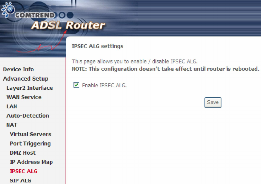
5.5.5 IPSEC ALG
IPSEC ALG provides multiple VPN passthrough connection support, allowing
different clients on LAN side to establish a secured IP Connection to the WAN server.
To enable IPSEC ALG, tick the checkbox and click the Save button.
63
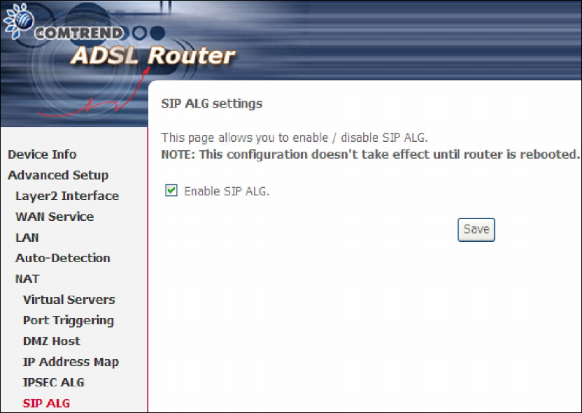
5.5.6 SIP ALG
This page allows you to enable / disable SIP ALG.
64
5.6 Security
To display this function, you must enable the firewall feature in WAN Setup.
For detailed descriptions, with examples, please consult Appendix A - Firewall.
5.6.1 IP Filtering
This screen sets filter rules that limit IP traffic (Outgoing/Incoming). Multiple filter
rules can be set and each applies at least one limiting condition. For individual IP
packets to pass the filter all conditions must be fulfilled.
NOTE: This function is not available when in bridge mode. Instead, 5.6.2 MAC
Filtering performs a similar function.
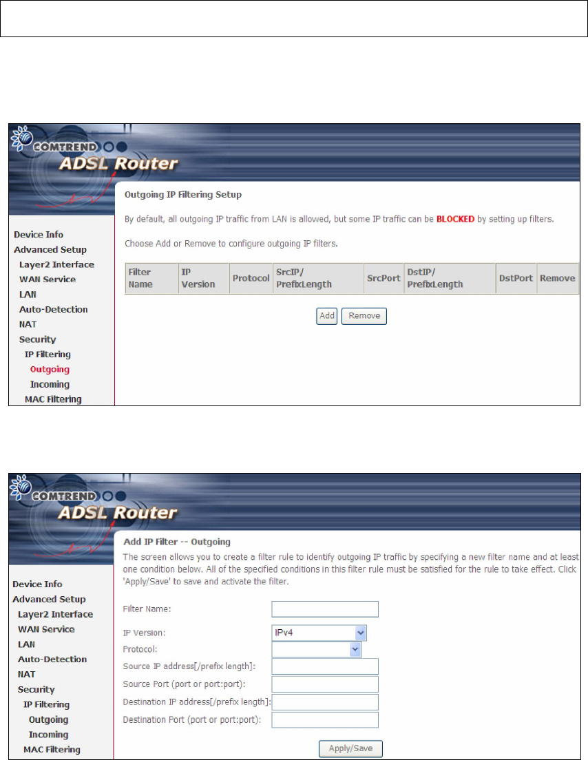
OUTGOING IP FILTER
By default, all outgoing IP traffic is allowed, but IP traffic can be blocked with filters.
To add a filter (to block some outgoing IP traffic), click the Add button.
On the following screen, enter your filter criteria and then click Apply/Save.
65
Consult the table below for field descriptions.
Field Description
Filter Name The filter rule label.
IP Version IPv4 selected by default.
Protocol TCP, TCP/UDP, UDP, or ICMP.
Source IP address Enter source IP address.
Source Port (port or port:port) Enter source port number or range.
Destination IP address Enter destination IP address.
Destination Port (port or port:port)
Enter destination port number or range.
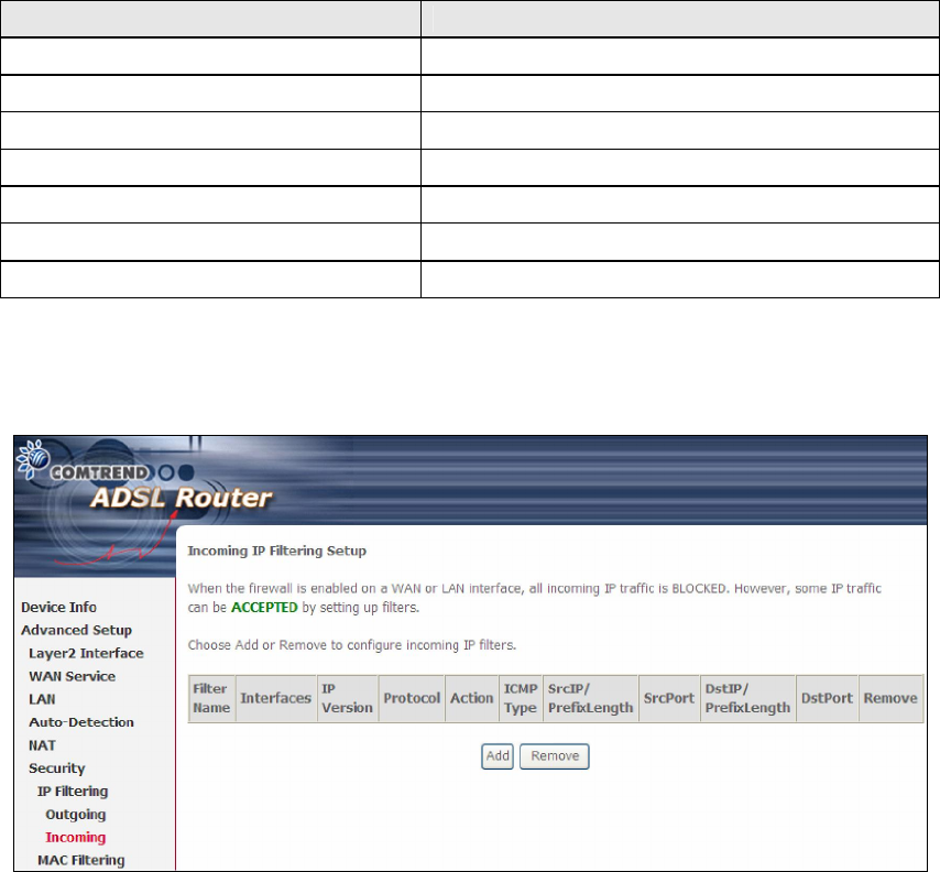
INCOMING IP FILTER
By default, all incoming IP traffic is blocked, but IP traffic can be allowed with filters.
To add a filter (to allow incoming IP traffic), click the Add button.
On the following screen, enter your filter criteria and then click Apply/Save.
66
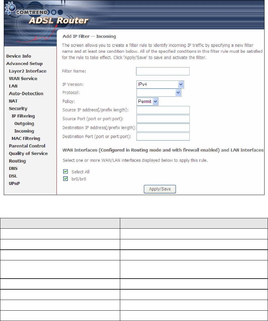
Consult the table below for field descriptions.
Field Description
Filter Name The filter rule label
IP Version IPv4 selected by default.
Protocol TCP, TCP/UDP, UDP, or ICMP.
Policy Permit/Drop packets specified by the firewall
rule.
Source IP address Enter source IP address.
Source Port (port or port:port) Enter source port number or range.
Destination IP address Enter destination IP address.
Destination Port (port or port:port)
Enter destination port number or range.
At the bottom of this screen, select the WAN and LAN Interfaces to which the filter
rule will apply. You may select all or just a subset. WAN interfaces in bridge mode or
without firewall enabled are not available.
67
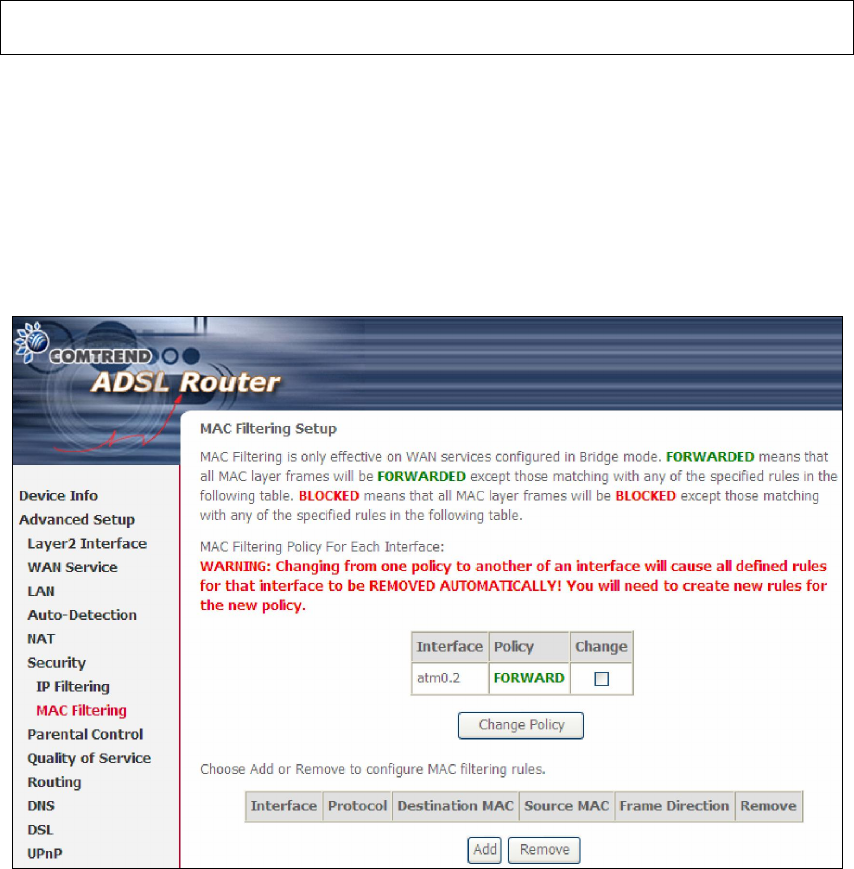
5.6.2 MAC Filtering
NOTE: This option is only available in bridge mode. Other modes use 5.6.1 IP
Filtering to perform a similar function.
Each network device has a unique 48-bit MAC address. This can be used to filter
(block or forward) packets based on the originating device. MAC filtering policy and
rules for the AR-5389 can be set according to the following procedure.
The MAC Filtering Global Policy is defined as follows. FORWARDED means that all
MAC layer frames will be FORWARDED except those matching the MAC filter rules.
BLOCKED means that all MAC layer frames will be BLOCKED except those
matching the MAC filter rules. The default MAC Filtering Global policy is
FORWARDED. It can be changed by clicking the Change Policy button.
Choose Add or Remove to configure MAC filtering rules. The following screen will
appear when you click Add. Create a filter to identify the MAC layer frames by
specifying at least one condition below. If multiple conditions are specified, all of
them must be met. Click Save/Apply to save and activate the filter rule.
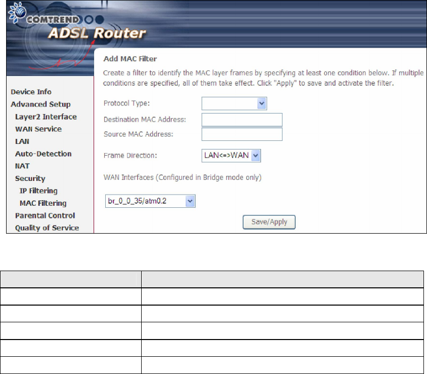
68
Consult the table below for detailed field descriptions.
Field Description
Protocol Type PPPoE, IPv4, IPv6, AppleTalk, IPX, NetBEUI, IGMP
Destination MAC Address
Defines the destination MAC address
Source MAC Address Defines the source MAC address
Frame Direction Select the incoming/outgoing packet interface
WAN Interfaces Applies the filter to the selected bridge interface.
6
9
5.7 Parental Control
This selection provides WAN access control functionality.
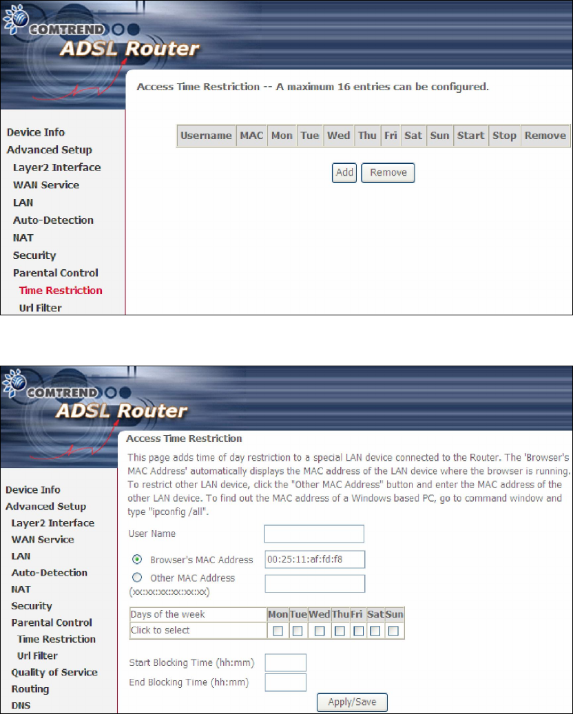
5.7.1 Time Restriction
This feature restricts access from a LAN device to an outside network through the
device on selected days at certain times. Make sure to activate the Internet Time
server synchronization as described in 8.5 Internet Time, so that the scheduled
times match your local time.
Click Add to display the following screen.
See below for field descriptions. Click Apply/Save to add a time restriction.
70
User Name: A user-defined label for this restriction.
Browser's MAC Address: MAC address of the PC running the browser.
Other MAC Address: MAC address of another LAN device.
Days of the Week: The days the restrictions apply.
Start Blocking Time: The time the restrictions start.
End Blocking Time: The time the restrictions end.
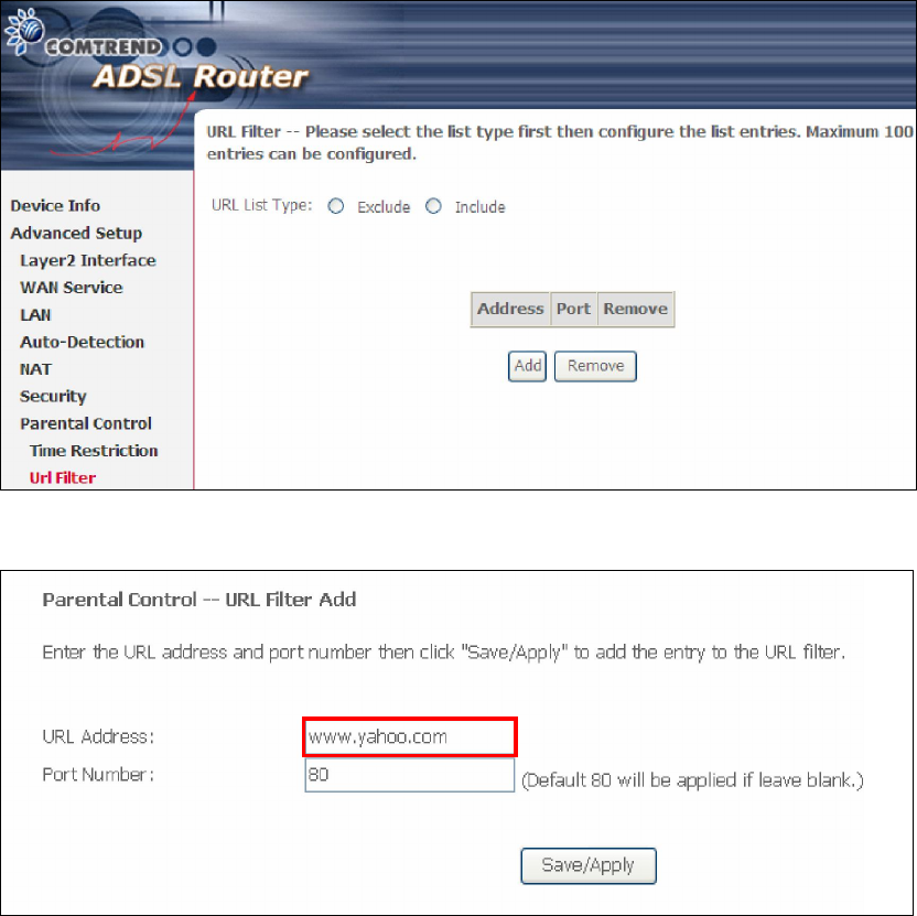
5.7.2 URL Filter
This screen allows for the creation of a filter rule for access rights to websites based
on their URL address and port number.
Select URL List Type: Exclude or Include. Then click Add to display the following
screen.
Enter the URL address and port number then click Save/Apply to add the entry to
the URL filter. URL Addresses begin with “www”, as shown in this example.
71
A maximum of 100 entries can be added to the URL Filter list.
Tick the Exclude radio button to deny access to the websites listed.
Tick the Include radio button to restrict access to only those listed websites.
72
5.8 Quality of Service (QoS)
NOTE: QoS must be enabled in at least one PVC to display this option.
(see Appendix E - Connection Setup for detailed PVC setup instructions).
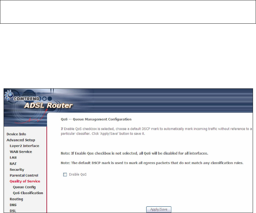
5.8.1 Queue Management Configuration
To Enable QoS tick the checkbox and select a Default DSCP Mark.
Click Apply/Save to activate QoS.
QoS and DSCP Mark are defined as follows:
Quality of Service (QoS): This provides different priority to different users or data
flows, or guarantees a certain level of performance to a data flow in accordance with
requests from Queue Prioritization.
Default Differentiated Services Code Point (DSCP) Mark: This specifies the
per hop behavior for a given flow of packets in the Internet Protocol (IP) header that
do not match any other QoS rule.
73
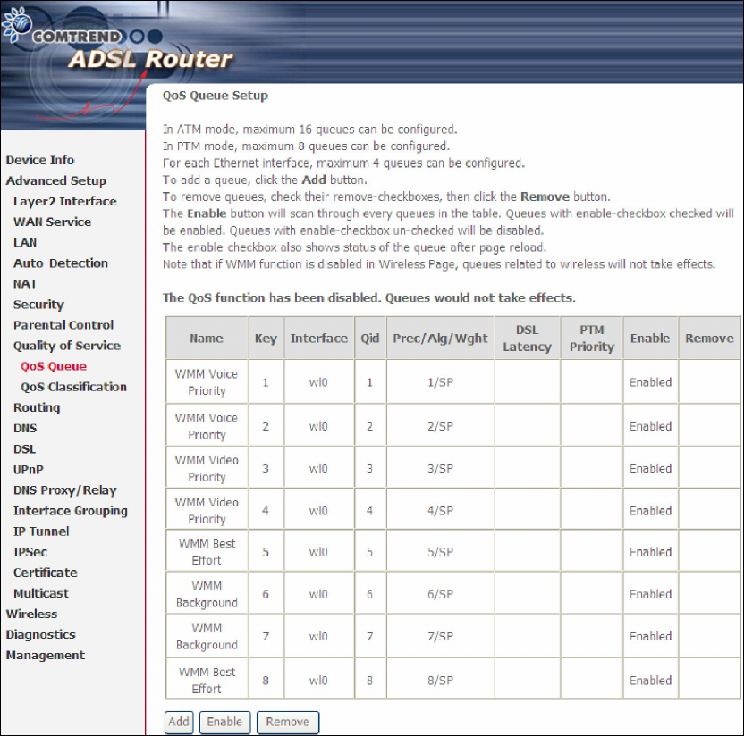
5.8.2 Queue Configuration
This function follows the Differentiated Services rule of IP QoS. You can create a new
Queue entry by clicking the Add button. Enable and assign an interface and
precedence on the next screen. Click Save/Reboot on this screen to activate it.
Click Enable to activate the QoS Queue. Click Add to display the following screen.
74
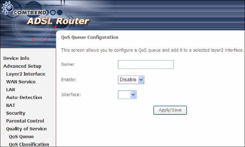
Name: Identifier for this Queue entry.
Enable: Enable/Disable the Queue entry.
Interface: Assign the entry to a specific network interface (QoS enabled).
75
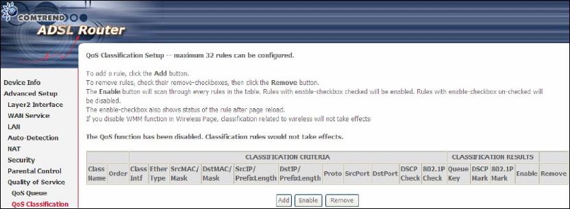
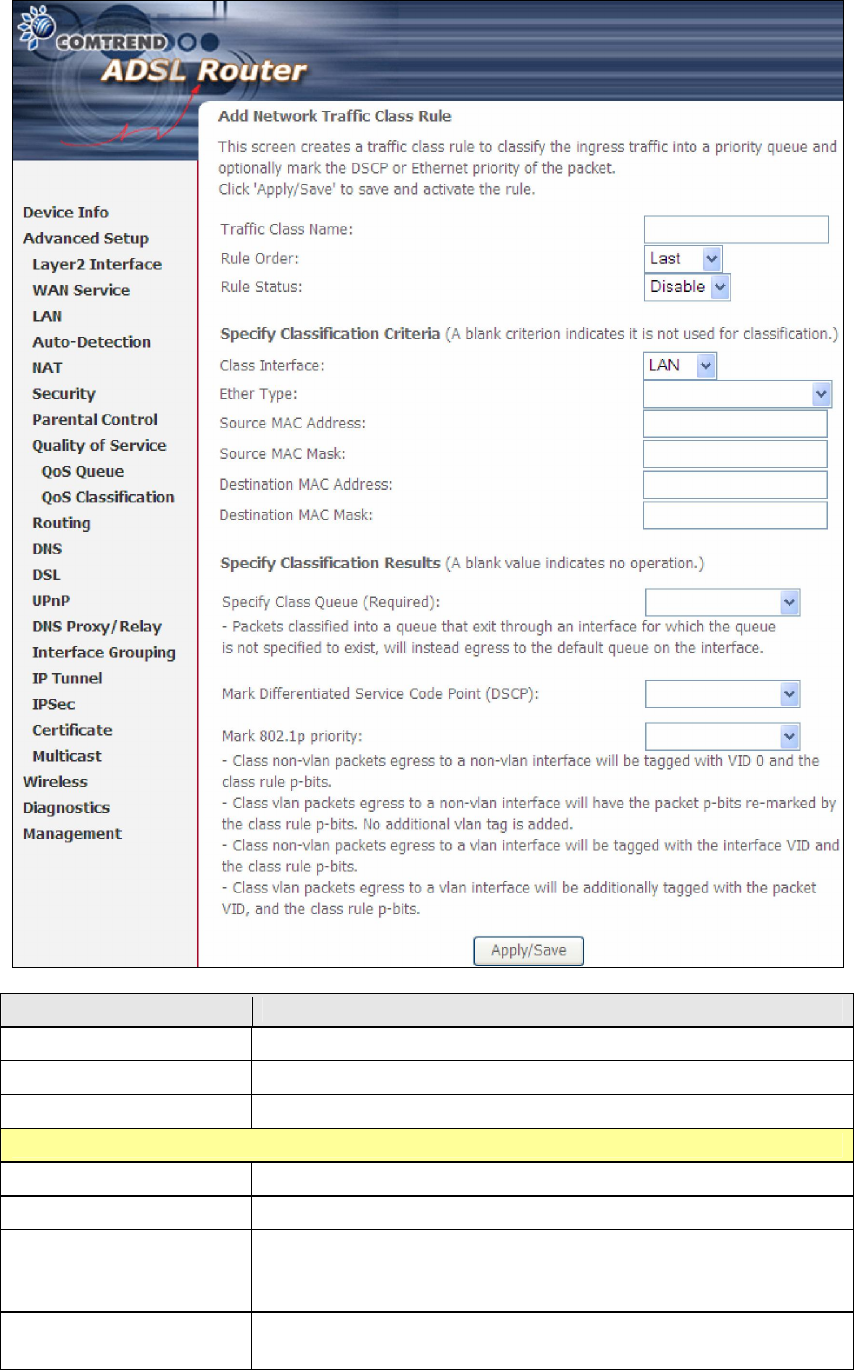
5.8.3 QoS Classification
The network traffic classes are listed in the following table.
Click Add to configure a network traffic class rule and Enable to activate it. To
delete an entry from the list, click Remove.
This screen creates a traffic class rule to classify the upstream traffic, assign
queuing priority and optionally overwrite the IP header DSCP byte. A rule consists of
a class name and at least one logical condition. All the conditions specified in the
rule must be satisfied for it to take effect.
76
Field Description
Traffic Class Name Enter a name for the traffic class.
Rule Order Last is the only option.
Rule Status Disable or enable the rule.
Classification Criteria
Class Interface Select an interface (i.e. Local, eth0-4, wl0)
Ether Type Set the Ethernet type (e.g. IP, ARP, IPv6).
Source MAC Address A packet belongs to SET-1, if a binary-AND of its source
MAC address with the Source MAC Mask is equal to the
binary-AND of the Source MAC Mask and this field.
Source MAC Mask This is the mask used to decide how many bits are checked
in Source MAC Address.
77
Field Description
Destination MAC
Address
A packet belongs to SET-1 then the result that the
Destination MAC Address of its header binary-AND to the
Destination MAC Mask must equal to the result that this
field binary-AND to the Destination MAC Mask.
Destination MAC Mask
This is the mask used to decide how many bits are checked
in Destination MAC Address.
Classification Results
Specify Class Queue
Select corresponding queue to deliver outgoing traffic.
Mark Differentiated
Service Code Point
The selected Code Point gives the corresponding priority to
packets that satisfy the rule.
Mark 802.1p Priority Select between 0-7. Lower values have higher priority.
78
5.9 Routing
These following routing functions are accessed from this menu:
Default Gateway, Static Route, Policy Routing and RIP.
NOTE: In bridge mode, the RIP menu option is hidden while the other menu
options are shown but ineffective.
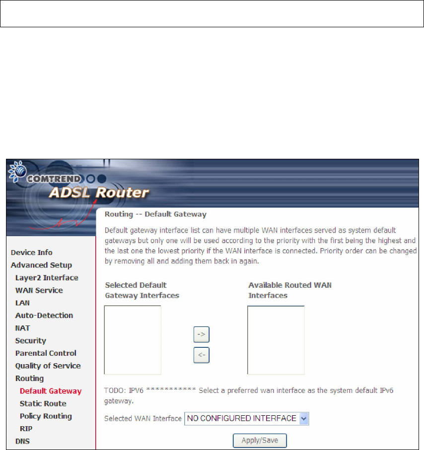
5.9.1 Default Gateway
Default gateway interface list can have multiple WAN interfaces served as system
default gateways but only one will be used according to the priority with the first
being the highest and the last one the lowest priority if the WAN interface is
connected. Priority order can be changed by removing all and adding them back in
again.
79
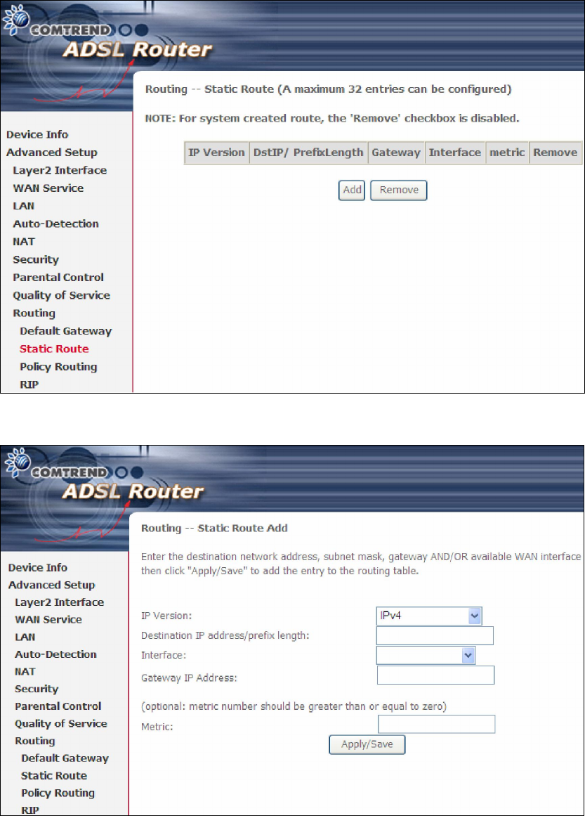
5.9.2 Static Route
This option allows for the configuration of static routes by destination IP.
Click Add to create a static route or click Remove to delete a static route.
After clicking Add the following screen will display.
Input the Destination IP Address, select the interface type, Input the Gateway IP,
(and the Metric number if required). Then, click Apply/Save to add an entry to the
routing table.
80
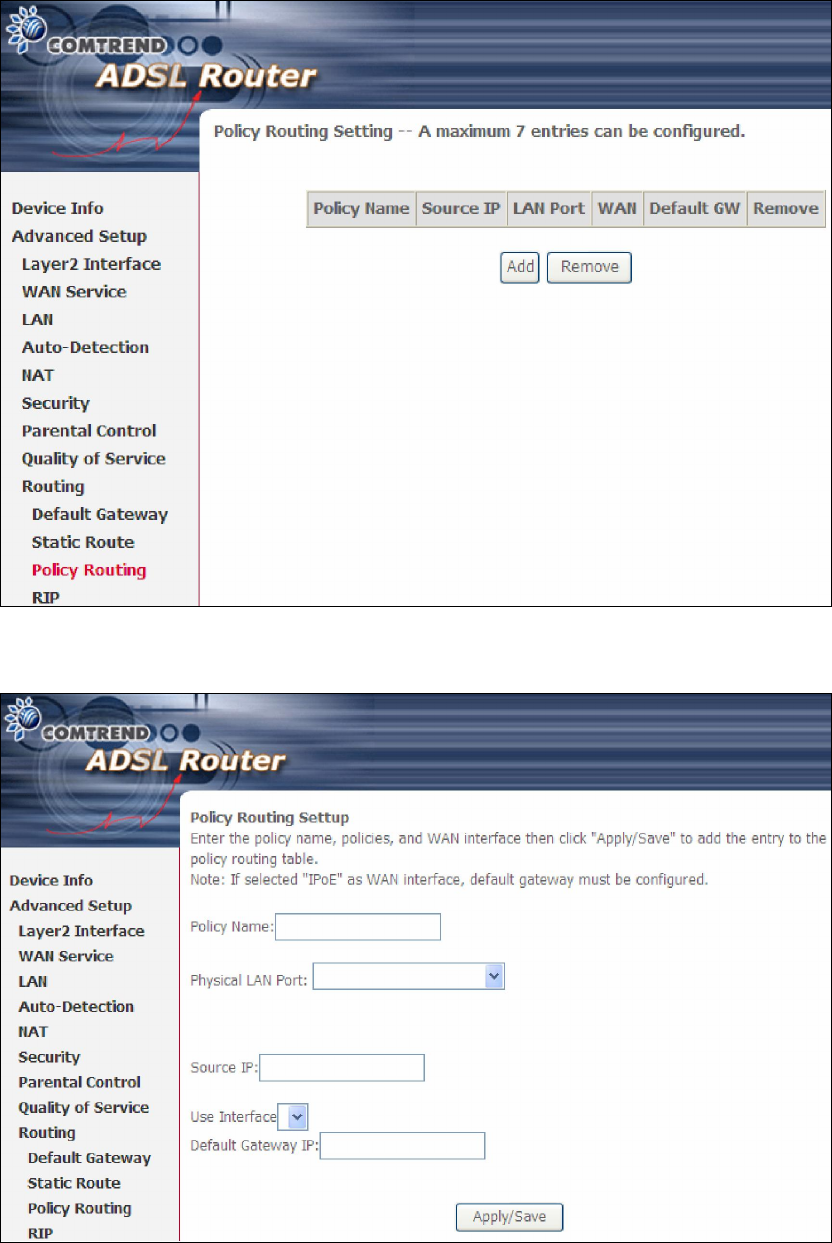
5.9.3 Policy Routing
This option allows for the configuration of static routes by policy.
Click Add to create a routing policy or Remove to delete one.
On the following screen, complete the form and click Apply/Save to create a policy.
81
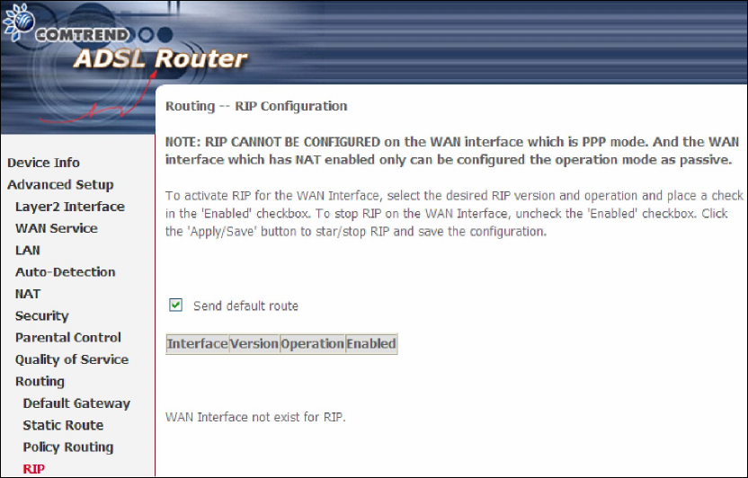
5.9.4 RIP
To activate RIP, configure the RIP version/operation mode and select the Enabled
checkbox for at least one WAN interface before clicking Save/Apply.
82
5.10 DNS
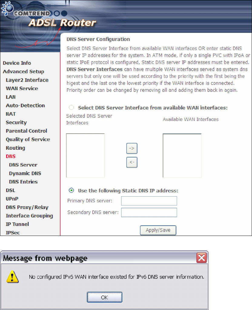
5.10.1 DNS Server
Select DNS Server Interface from available WAN interfaces OR enter static DNS
server IP addresses for the system. In ATM mode, if only a single PVC with IPoA or
static IPoE protocol is configured, Static DNS server IP addresses must be entered.
DNS Server Interfaces can have multiple WAN interfaces served as system dns
servers but only one will be used according to the priority with the first being the
highest and the last one the lowest priority if the WAN interface is connected.
Priority order can be changed by removing all and adding them back in again.
If is no IPv6 WAN interface is configured, a warning message system will pop up when
accessing DNS Server.
83
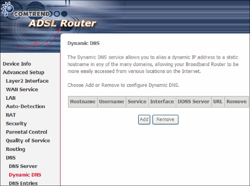
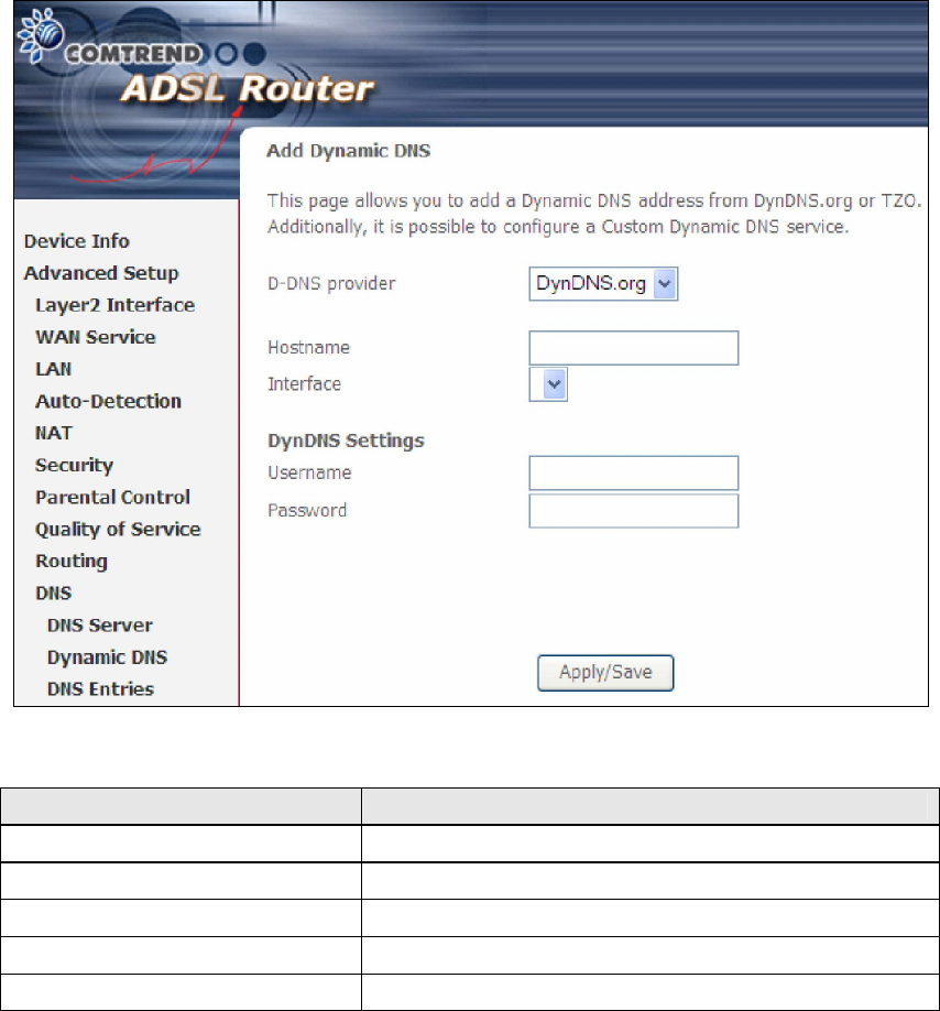
5.10.2 Dynamic DNS
The Dynamic DNS service allows you to map a dynamic IP address to a static
hostname in any of many domains, allowing the AR-5389 to be more easily accessed
from various locations on the Internet.
To add a dynamic DNS service, click Add. The following screen will display.
84
Consult the table below for field descriptions.
Field Description
D-DNS provider Select a dynamic DNS provider from the list
Hostname Enter the name of the dynamic DNS server
Interface Select the interface from the list
Username Enter the username of the dynamic DNS server
Password Enter the password of the dynamic DNS server
85
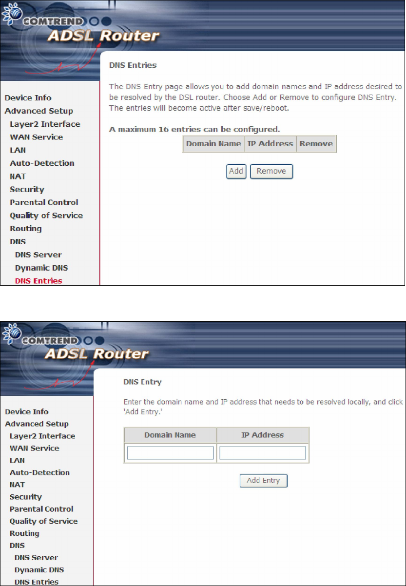
5.10.3 DNS Entries
The DNS Entry page allows you to add domain names and IP address desired to be
resolved by the DSL router.
Choose Add or Remove to configure DNS Entry. The entries will become active after
save/reboot.
Enter the domain name and IP address that needs to be resolved locally, and click
the Add Entry button.
86
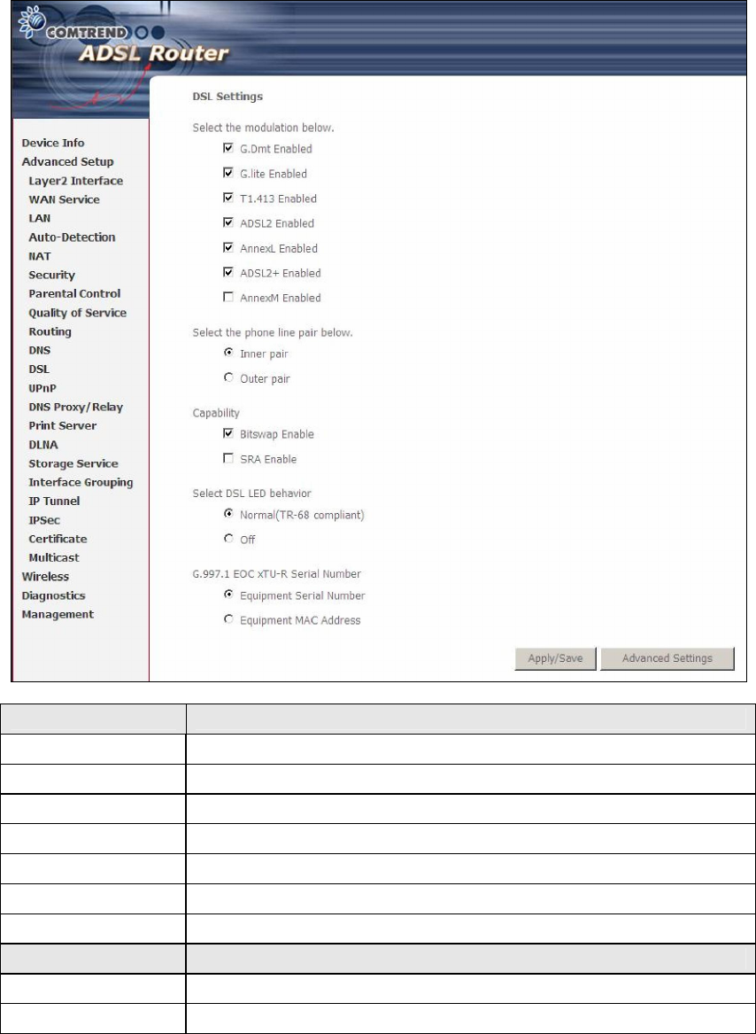
5.11 DSL
The DSL Settings screen allows for the selection of DSL modulation modes.
For optimum performance, the modes selected should match those of your ISP.
DSL Mode Data Transmission Rate - Mbps (Megabits per second)
G.Dmt Downstream: 12 Mbps Upstream: 1.3 Mbps
G.lite Downstream: 4 Mbps Upstream: 0.5 Mbps
T1.413 Downstream: 8 Mbps Upstream: 1.0 Mbps
ADSL2 Downstream: 12 Mbps Upstream: 1.0 Mbps
AnnexL Supports longer loops but with reduced transmission rates
ADSL2+ Downstream: 24 Mbps Upstream: 1.0 Mbps
AnnexM Downstream: 24 Mbps Upstream: 3.5 Mbps
Options Description
Inner/Outer Pair Select the inner or outer pins of the twisted pair (RJ11 cable)
Bitswap Enable Enables adaptive handshaking functionality
87
DSL Mode Data Transmission Rate - Mbps (Megabits per second)
SRA Enable Enables Seamless Rate Adaptation (SRA)
DSL LED behavior
Normal (TR-68 compliant) – DSL LED blink/on/off following
TR-68 standard Off – always turn off DSL LED
G997.1 EOC
xTU-R Serial
Number
Select Equipment Serial Number or Equipment MAC Address to
use router’s serial number or MAC address in ADSL EOC
messages
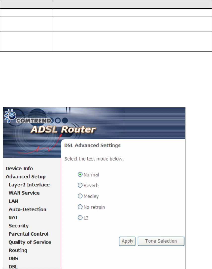
Advanced DSL Settings
Click Advanced Settings to reveal additional options. On the following screen you
can select a test mode or modify tones by clicking Tone Selection. Click Apply to
implement these settings and return to the previous screen.
On this screen you select the tones you want activated, then click Apply and Close.
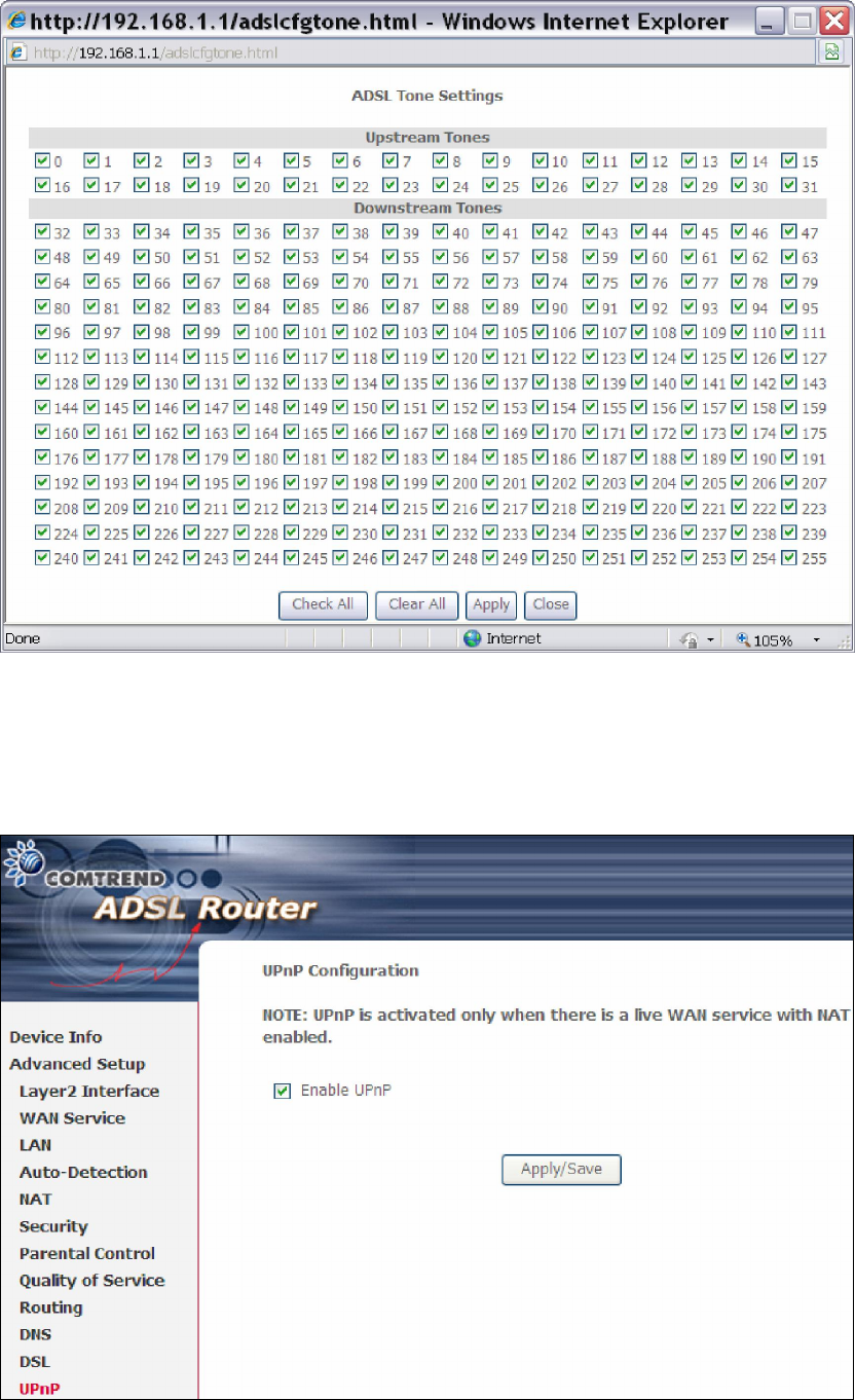
88
5.12 UPnP
Select the checkbox provided and click Apply/Save to enable UPnP protocol.
89
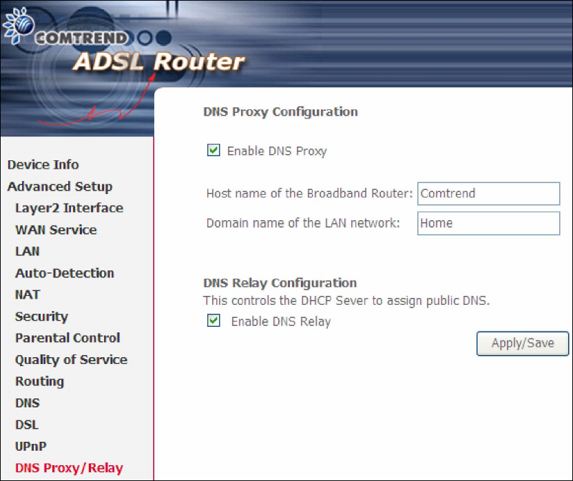
5.13 DNS Proxy/Relay
DNS proxy receives DNS queries and forwards DNS queries to the Internet. After the
CPE gets answers from the DNS server, it replies to the LAN clients. Configure DNS
proxy with the default setting, when the PC gets an IP via DHCP, the domain name,
Home, will be added to PC’s DNS Suffix Search List, and the PC can access route with
“Comtrend.Home”.
DNS Relay
When DNS Relay is enabled, the router will play a role as DNS server that send
request to ISP DNS server and cache the information for later access. When DNS
relay is disabled, the computer will pull information from ISP DNS server.
90
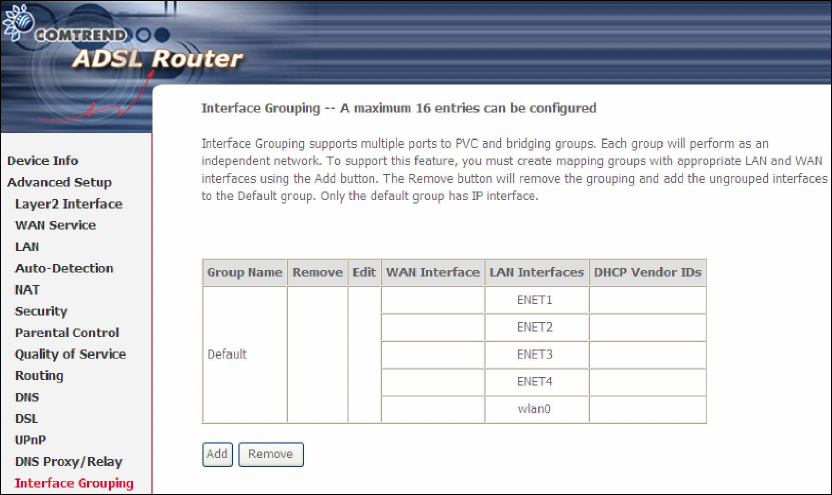
5.14 Interface Grouping
Interface Grouping supports multiple ports to PVC and bridging groups. Each group
performs as an independent network. To use this feature, you must create mapping
groups with appropriate LAN and WAN interfaces using the Add button.
The Remove button removes mapping groups, returning the ungrouped interfaces
to the Default group. Only the default group has an IP interface.
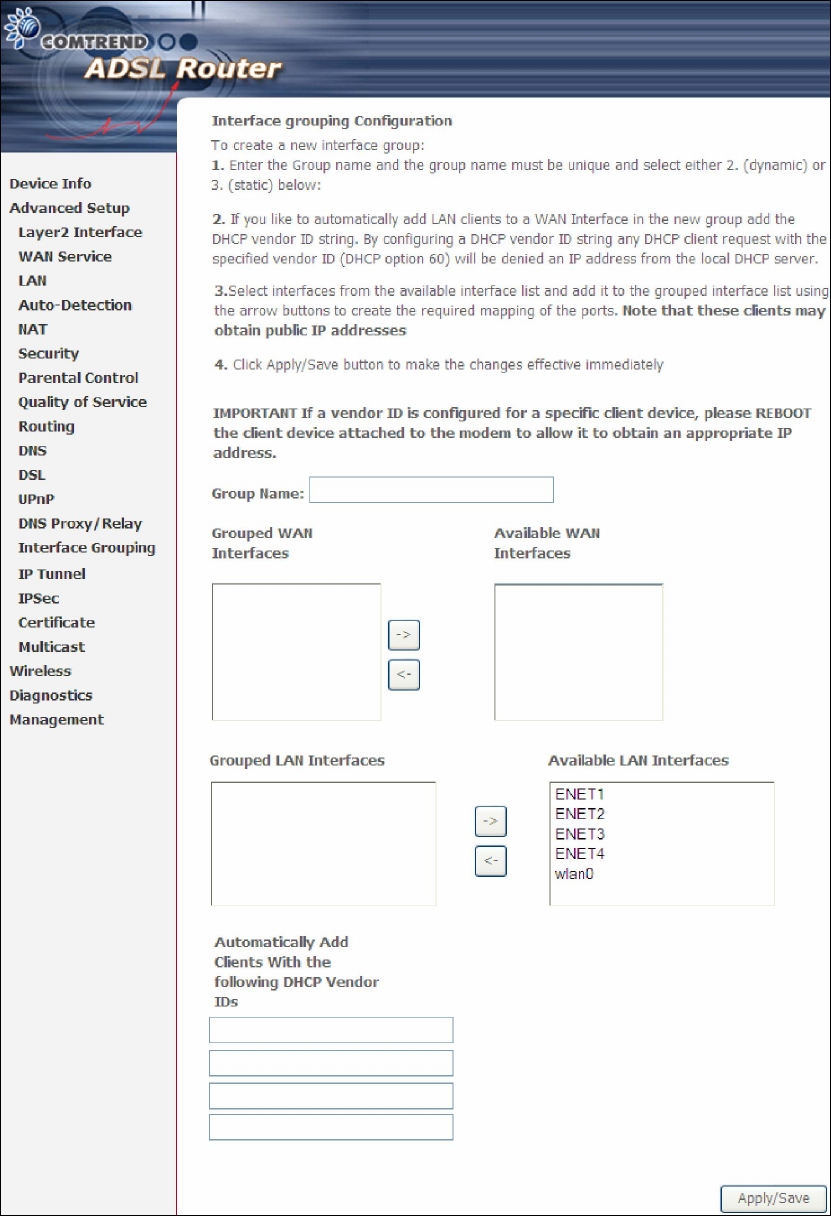
To add an Interface Group, click the Add button. The following screen will appear.
It lists the available and grouped interfaces. Follow the instructions shown
onscreen.
91
Automatically Add Clients With Following DHCP Vendor IDs:
Add support to automatically map LAN interfaces to PVC's using DHCP vendor ID
(option 60). The local DHCP server will decline and send the requests to a remote
DHCP server by mapping the appropriate LAN interface. This will be turned on when
Interface Grouping is enabled.
92
For example, imagine there are 4 PVCs (0/33, 0/36, 0/37, 0/38). VPI/VCI=0/33 is
for PPPoE while the other PVCs are for IP set-top box (video). The LAN interfaces are
ENET1, ENET2, ENET3, and ENET4.
The Interface Grouping configuration will be:
1. Default: ENET1, ENET2, ENET3, and ENET4.
2. Video: nas_0_36, nas_0_37, and nas_0_38. The DHCP vendor ID is "Video".
If the onboard DHCP server is running on "Default" and the remote DHCP server is
running on PVC 0/36 (i.e. for set-top box use only). LAN side clients can get IP
addresses from the CPE's DHCP server and access the Internet via PPPoE (0/33).
If a set-top box is connected to ENET1 and sends a DHCP request with vendor ID
"Video", the local DHCP server will forward this request to the remote DHCP server.
The Interface Grouping configuration will automatically change to the following:
1. Default: ENET2, ENET3, and ENET4
2. Video: nas_0_36, nas_0_37, nas_0_38, and ENET1.
93
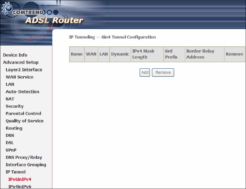
5.15 IP Tunnel
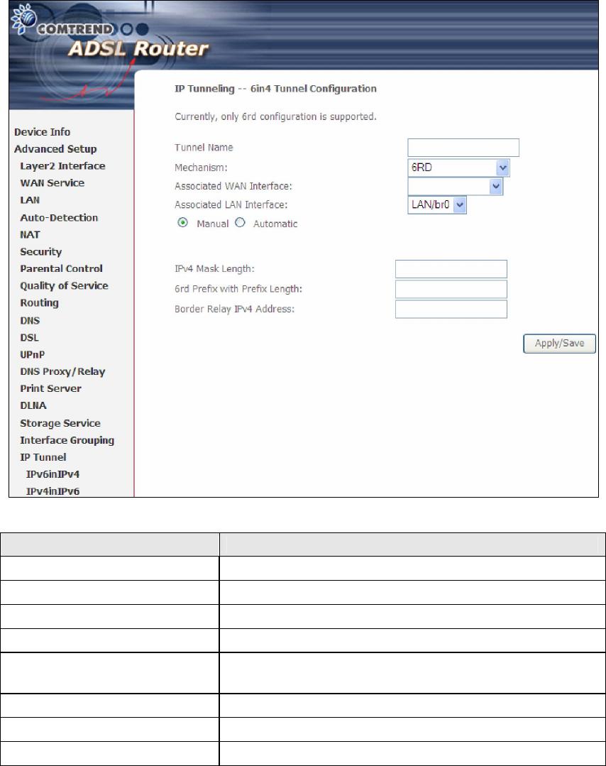
5.15.1 IPv6inIPv4
Configure 6in4 tunneling to encapsulate IPv6 traffic over explicitly-configured IPv4
links.
Click the Add button to display the following.
94
Options Description
Tunnel Name Input a name for the tunnel
Mechanism Mechanism used by the tunnel deployment
Associated WAN Interface Select the WAN interface to be used by the tunnel
Associated LAN Interface Select the LAN interface to be included in the tunnel
Manual/Automatic Select automatic for point-to-multipoint tunneling /
manual for point-to-point tunneling
IPv4 Mask Length The subnet mask length used for the IPv4 interface
6rd Prefix with Prefix Length
Prefix and prefix length used for the IPv6 interface
Border Relay IPv4 Address Input the IPv4 address of the other device
95
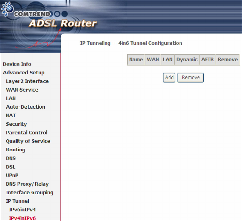
5.15.2 IPv4inIPv6
Configure 4in6 tunneling to encapsulate IPv4 traffic over an IPv6-only environment.
Click the Add button to display the following.
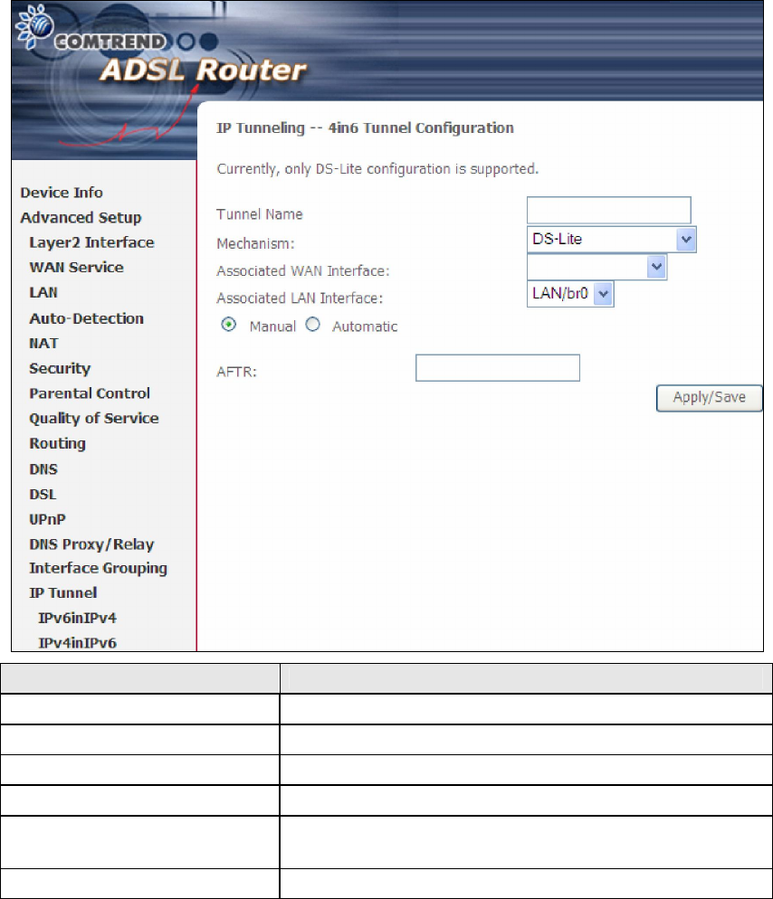
96
Options Description
Tunnel Name Input a name for the tunnel
Mechanism Mechanism used by the tunnel deployment
Associated WAN Interface Select the WAN interface to be used by the tunnel
Associated LAN Interface Select the LAN interface to be included in the tunnel
Manual/Automatic Select automatic for point-to-multipoint tunneling /
manual for point-to-point tunneling
AFTR Address of Address Family Translation Router
97
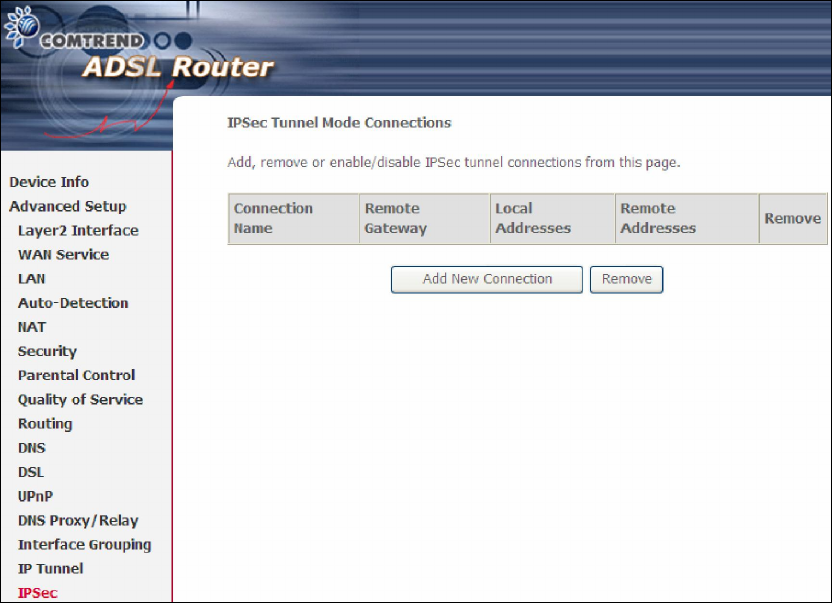
5.16 IPSec
You can add, edit or remove IPSec tunnel mode connections from this page.
Click Add New Connection to add a new IPSec termination rule.
The following screen will display.
98
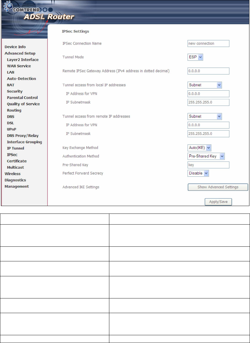
IPSec Connection Name User-defined label
Tunnel Mode Select tunnel protocol, AH (Authentication
Header) or ESP (Encapsulating Security
Payload) for this tunnel.
Remote IPSec Gateway Address The location of the Remote IPSec Gateway. IP
address or domain name can be used.
Tunnel access from local IP
addresses
Specify the acceptable host IP on the local
side. Choose Single or Subnet.
IP Address/Subnet Mask for VPN If you chose Single, please enter the host IP
address for VPN. If you chose Subnet
, please
enter the subnet information for VPN.
Tunnel access from remote IP
addresses
Specify the acceptable host IP on the remote
side. Choose Single or Subnet.
IP Address/Subnet Mask for VPN If you chose Single, please enter the host IP
address for VPN. If you chose Subnet
, please
enter the subnet information for VPN.
Key Exchange Method Select from Auto(IKE) or Manual
For the Auto(IKE) key exchange method, select Pre-shared key or Certificate (X.509)
authentication. For Pre-shared key authentication you must enter a key, while for
Certificate (X.509) authentication you must select a certificate from the list.
See the tables below for a summary of all available options.