Comtrend AR5313U Wireless ADSL2+ Router User Manual AR 5313u
Comtrend Corporation Wireless ADSL2+ Router AR 5313u
Comtrend >
Contents
- 1. User Manual-1
- 2. User Manual-2
- 3. User Manual-3
User Manual-3

130
Close the browser and wait for 2 minutes before reopening it. It may also be necessary, to
reconfigure your PC IP configuration to match any new settings.
NOTE: This entry has the same effect as the Reset button. The AR-5313u board hardware and
the boot loader support the reset to default. If the Reset button is continuously
pressed for more than 10 seconds, the boot loader will erase the configuration data
saved in flash memory.
131
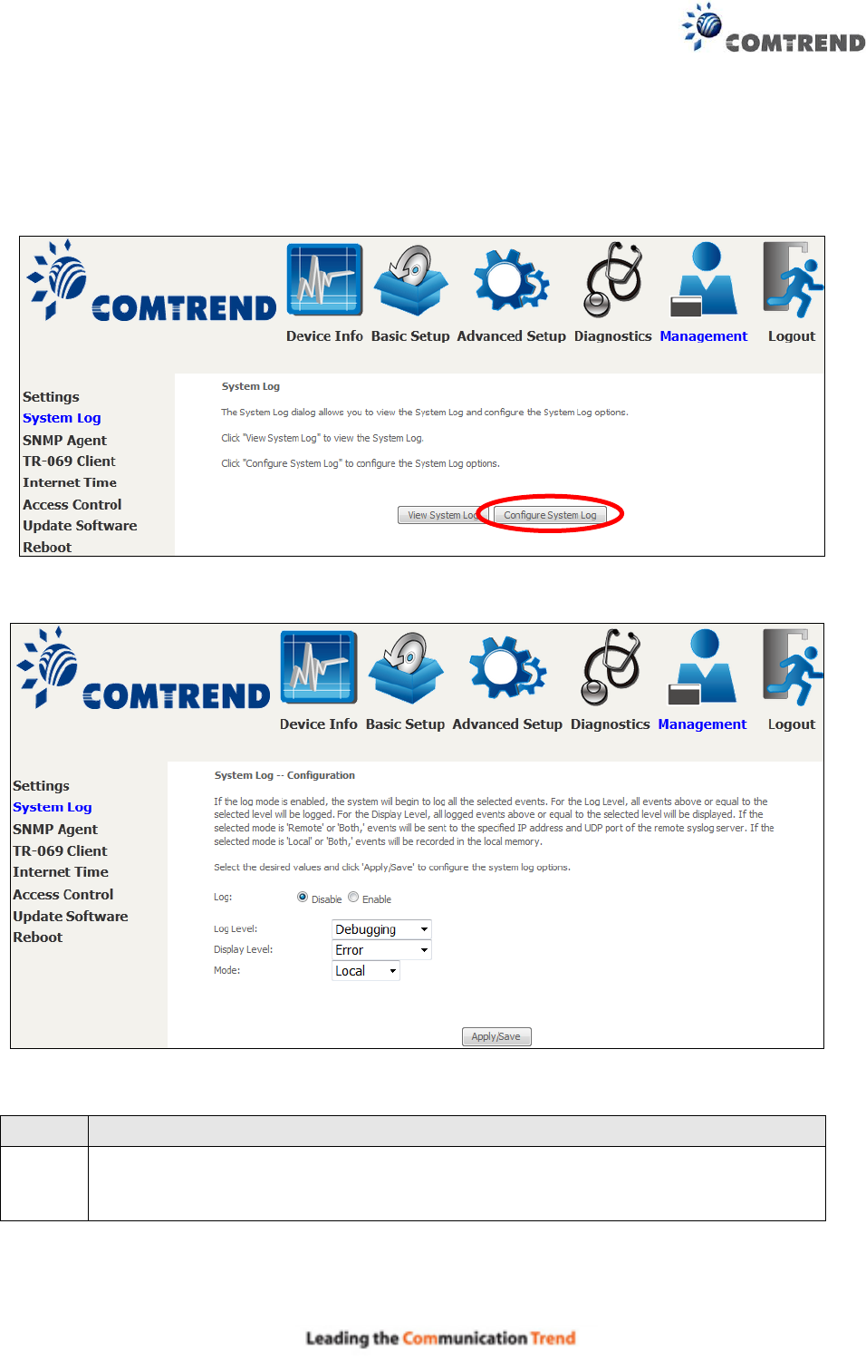
8.2 System Log
This function allows a system log to be kept and viewed upon request.
Follow the steps below to configure, enable, and view the system log.
STEP 1: Click Configure System Log, as shown below (circled in Red).
STEP 2: Select desired options and click Apply/Save.
Consult the table below for detailed descriptions of each system log option.
Option
Description
Log
Indicates whether the system is currently recording events. The user can
enable or disable event logging. By default, it is disabled. To enable it, select
the Enable radio button and then click Apply/Save.

132
Option
Description
Log
Level
Allows you to configure the event level and filter out unwanted events below this
level. The events ranging from the highest critical level “Emergency” down to
this configured level will be recorded to the log buffer on the AR-5313u SDRAM.
When the log buffer is full, the newer event will wrap up to the top of the log
buffer and overwrite the old event. By default, the log level is “Debugging”,
which is the lowest critical level.
The log levels are defined as follows:
Emergency = system is unusable
Alert = action must be taken immediately
Critical = critical conditions
Error = Error conditions
Warning = normal but significant condition
Notice= normal but insignificant condition
Informational= provides information for reference
Debugging = debug-level messages
Emergency is the most serious event level, whereas Debugging is the least
important. For instance, if the log level is set to Debugging, all the events from
the lowest Debugging level to the most critical level Emergency level will be
recorded. If the log level is set to Error, only Error and the level above will be
logged.
Display
Level
Allows the user to select the logged events and displays on the View System
Log window for events of this level and above to the highest Emergency level.
Mode
Allows you to specify whether events should be stored in the local memory, or be
sent to a remote system log server, or both simultaneously. If remote mode is
selected, view system log will not be able to display events saved in the remote
system log server.
When either Remote mode or Both mode is configured, the WEB UI will prompt
the user to enter the Server IP address and Server UDP port.
STEP 3: Click View System Log. The results are displayed as follows.
133
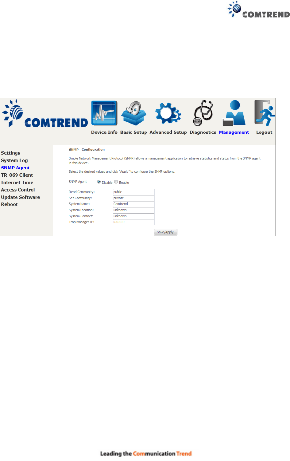
8.3 SNMP Agent
Simple Network Management Protocol (SNMP) allows a management application to retrieve
statistics and status from the SNMP agent in this device. Select the Enable radio button,
configure options, and click Save/Apply to activate SNMP.
134
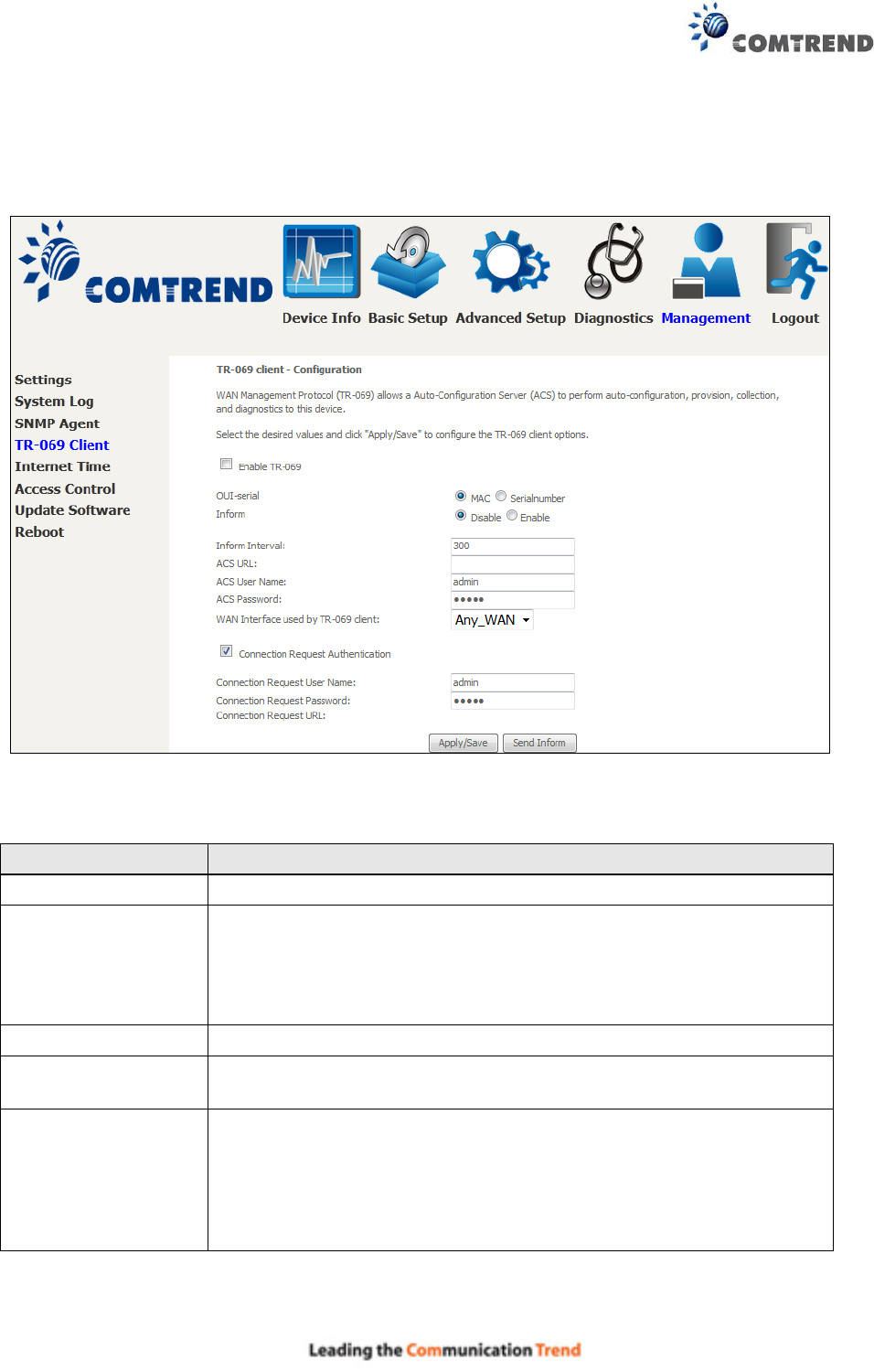
8.4 TR-069 Client
WAN Management Protocol (TR-069) allows an Auto-Configuration Server (ACS) to perform
auto-configuration, provision, collection, and diagnostics to this device. Select desired values
and click Apply/Save to configure TR-069 client options.
The table below is provided for ease of reference.
Option
Description
Enable TR-069
Tick the checkbox to enable.
OUI-serial
The serial number used to identify the CPE when making a
connection to the ACS using the CPE WAN Management
Protocol. Select MAC to use the router’s MAC address as serial
number to authenticate with ACS or select serial number to use
router’s serial number.
Inform
Disable/Enable TR-069 client on the CPE.
Inform Interval
The duration in seconds of the interval for which the CPE MUST
attempt to connect with the ACS and call the Inform method.
ACS URL
URL for the CPE to connect to the ACS using the CPE WAN
Management Protocol. This parameter MUST be in the form of a
valid HTTP or HTTPS URL. An HTTPS URL indicates that the ACS
supports SSL. The “host” portion of this URL is used by the CPE for
validating the certificate from the ACS when using
certificate-based authentication.

135
Option
Description
ACS User Name
Username used to authenticate the CPE when making a connection
to the ACS using the CPE WAN Management Protocol. This
username is used only for HTTP-based authentication of the CPE.
ACS Password
Password used to authenticate the CPE when making a connection
to the ACS using the CPE WAN Management Protocol. This
password is used only for HTTP-based authentication of the CPE.
WAN Interface used
by TR-069 client
Choose Any_WAN, LAN, Loopback or a configured connection.
Connection Request
Authentication
Tick the checkbox to enable.
User Name
Username used to authenticate an ACS making a Connection
Request to the CPE.
Password
Password used to authenticate an ACS making a Connection
Request to the CPE.
URL
IP address and port the ACS uses to connect to router.
The Send Inform button forces the CPE to establish an immediate connection to the ACS.
136
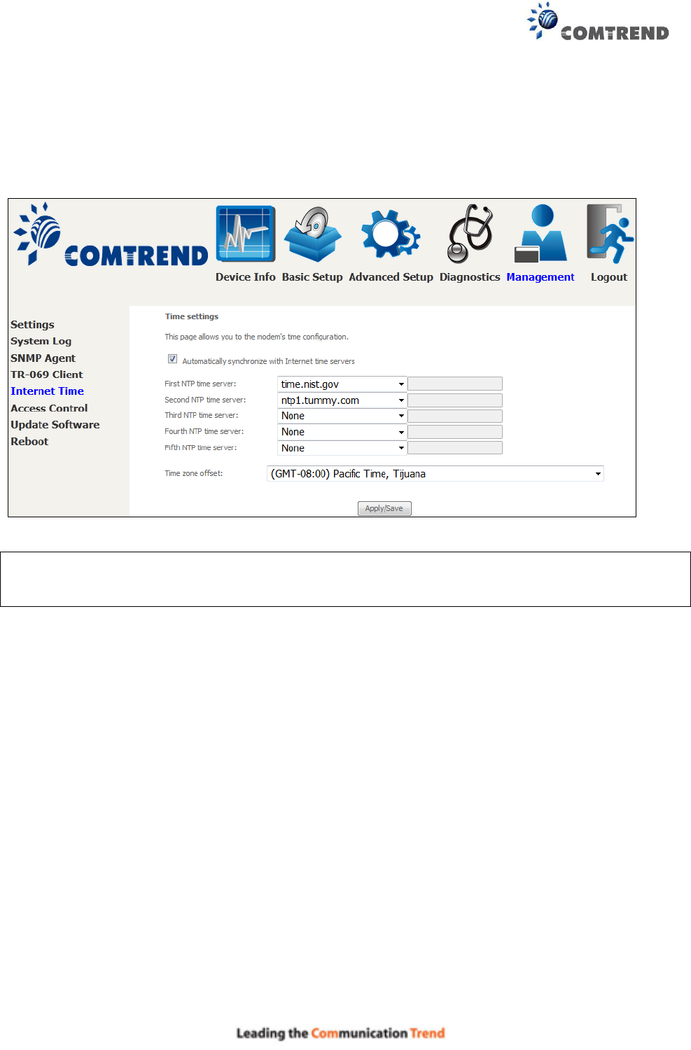
8.5 Internet Time
This option automatically synchronizes the router time with Internet timeservers. To enable
time synchronization, tick the corresponding checkbox , choose your preferred time server(s),
select the correct time zone offset, and click Save/Apply.
NOTE: Internet Time must be activated to use Parental Control.
In addition, this menu item is not displayed when in Bridge mode since the router
would not be able to connect to the NTP timeserver.

137
8.6 Access Control
8.6.1 Accounts
This screen is used to configure the user account access passwords for the device. Access to the
AR-5313u is controlled through the following user accounts:
The root account has unrestricted access to view and change the configuration of your
Broadband router.
The support account is typically utilized by Carrier/ISP technicians for maintenance and
diagnostics.
The user account is typically utilized by End-Users to view configuration settings and
statistics, with limited ability to configure certain settings.
The apuser account is typically utilized by End-Users to view configuration settings and
statistics, with limited ability to configure wireless settings.
Use the fields to update passwords for the accounts, add/remove accounts (max of 5 accounts) as
well as adjust their specific privileges.
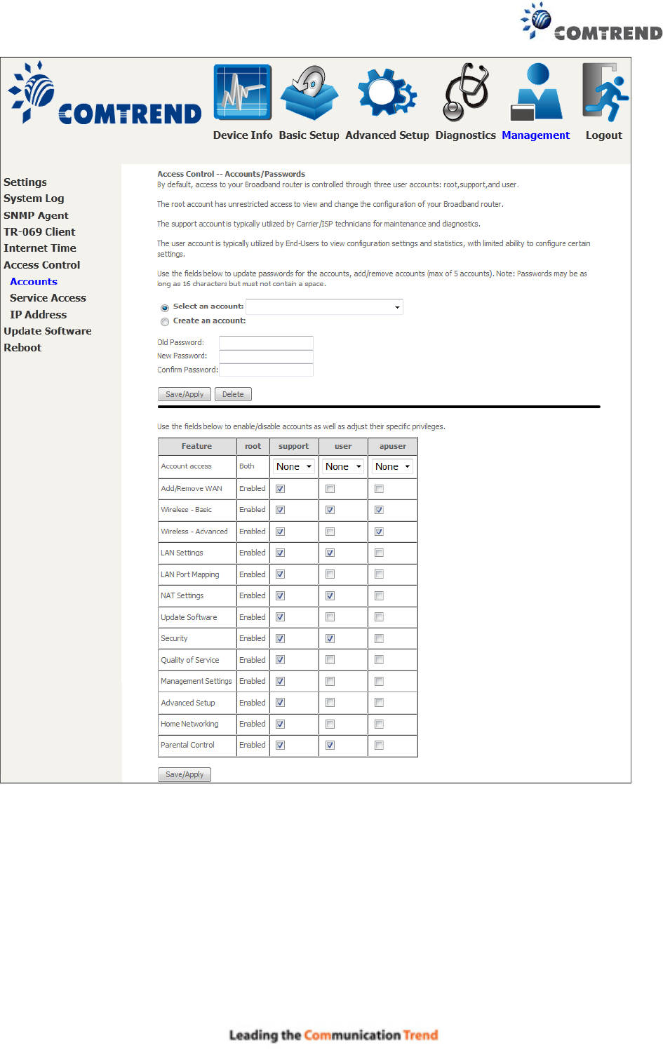
138
Note: Passwords may be as long as 16 characters but must not contain a space. Click
Save/Apply to continue.
139
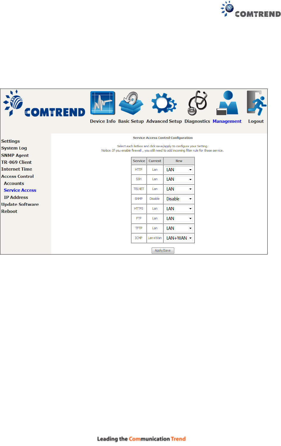
8.6.2 Service Access
The Services option limits or opens the access services over the LAN or WAN. These access
services available are: HTTP, SSH, TELNET, SNMP, HTTPS, FTP, TFTP and ICMP. Enable a service
by selecting its dropdown listbox. Click APPLY/SAVE to activate.
140
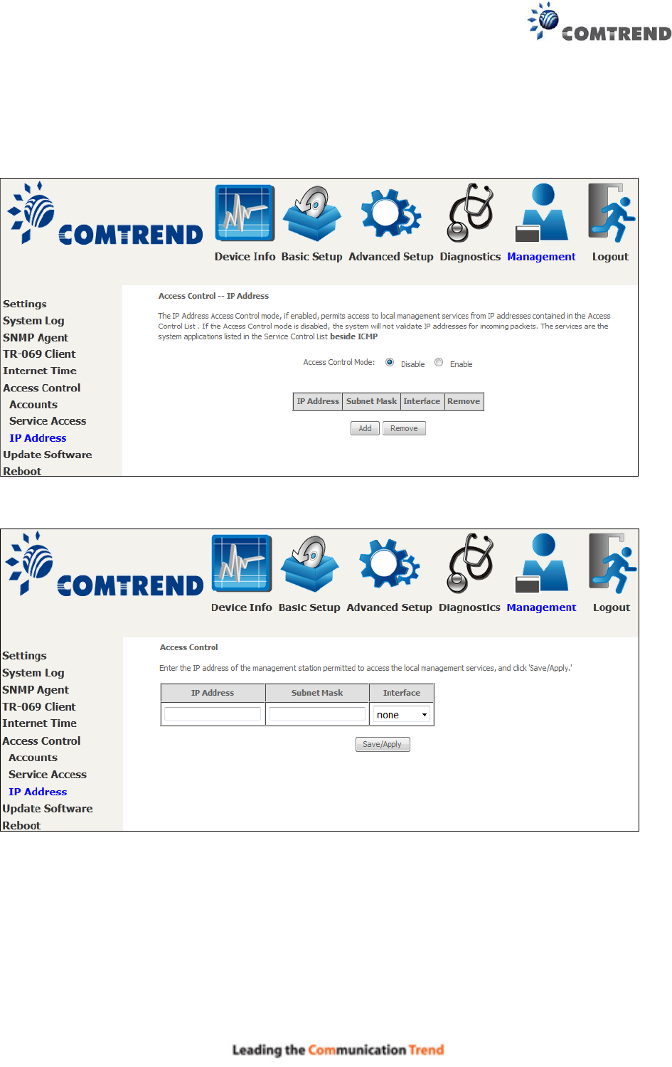
8.6.3 IP Address
The IP Address Access Control mode, if enabled, permits access to local management services
from IP addresses contained in the Access Control List. If the Access Control mode is disabled, the
system will not validate IP addresses for incoming packets. The services are the system
applications listed in the Service Control List beside ICMP.
Click the Add button to display the following.
Configure the address and subnet of the management station permitted to access the local
management services, and click Save/Apply.
IP Address – IP address of the management station.
Subnet Mask – Subnet address for the management station.
Interface – Access permission for the specified address, allowing the address to access the local
management service from none/lan/wan/lan&wan interfaces.

140
8.6.3 IP Address
The IP Address Access Control mode, if enabled, permits access to local management services
from IP addresses contained in the Access Control List. If the Access Control mode is disabled, the
system will not validate IP addresses for incoming packets. The services are the system
applications listed in the Service Control List beside ICMP.
Click the Add button to display the following.
Configure the address and subnet of the management station permitted to access the local
management services, and click Save/Apply.
IP Address – IP address of the management station.
Subnet Mask – Subnet address for the management station.
Interface – Access permission for the specified address, allowing the address to access the local
management service from none/lan/wan/lan&wan interfaces.
141
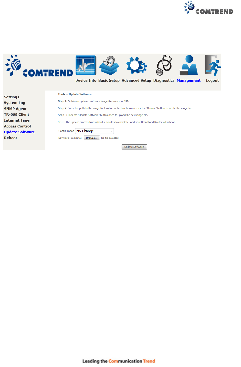
8.7 Update Software
This option allows for firmware upgrades from a locally stored file.
STEP 1: Obtain an updated software image file from your ISP.
STEP 2: Select the configuration from the drop-down menu.
Configuration options:
No change – upgrade software directly.
Erase current config – If the router has save_default configuration, this option will erase the
current configuration and restore to save_default configuration after software upgrade.
Erase All – Router will be restored to factory default configuration after software upgrade.
STEP 3: Enter the path and filename of the firmware image file in the Software File Name
field or click the Browse button to locate the image file.
STEP 4: Click the Update Software button once to upload and install the file.
NOTE: The update process will take about 2 minutes to complete. The device will reboot and
the browser window will refresh to the default screen upon successful installation. It is
recommended that you compare the Software Version on the Device Information
screen with the firmware version installed, to confirm the installation was successful.
142
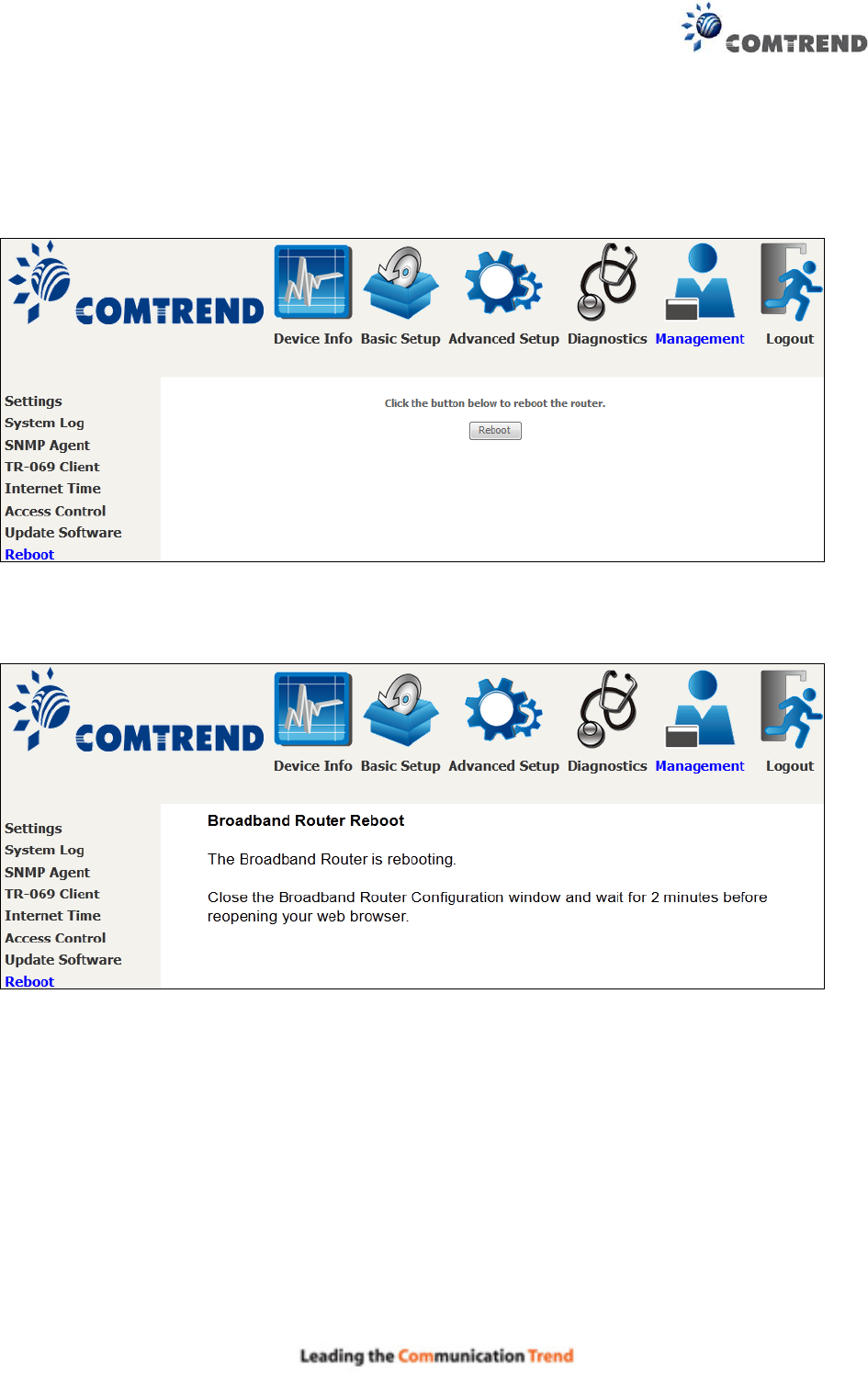
8.8 Reboot
To save the current configuration and reboot the router, click Save/Reboot.
NOTE: You may need to close the browser window and wait for 2 minutes before reopening it.
It may also be necessary, to reset your PC IP configuration.
143
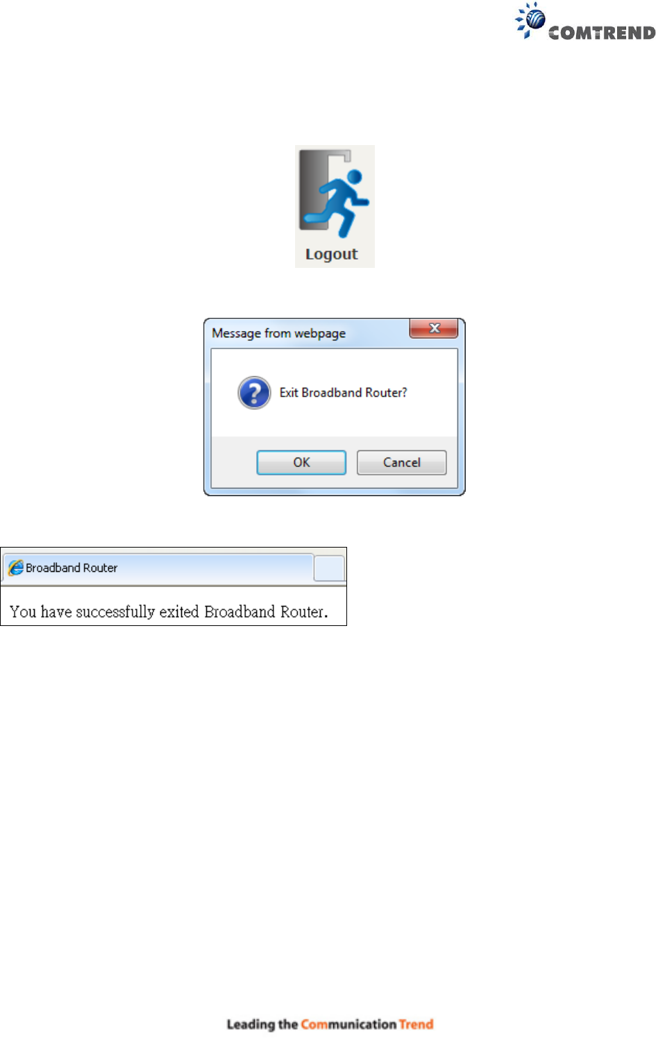
Chapter 9 Logout
To log out from the device simply click the following icon located at the top of your screen.
When the following window pops up, click the OK button to exit the router.
Upon successful exit, the following message will be displayed.

144
Appendix A - Firewall
STATEFUL PACKET INSPECTION
Refers to an architecture, where the firewall keeps track of packets on each connection traversing
all its interfaces and makes sure they are valid. This is in contrast to static packet filtering which
only examines a packet based on the information in the packet header.
DENIAL OF SERVICE ATTACK
Is an incident in which a user or organization is deprived of the services of a resource they would
normally expect to have. Various DoS attacks the device can withstand are ARP Attack, Ping
Attack, Ping of Death, Land, SYN Attack, Smurf Attack, and Tear Drop.
TCP/IP/PORT/INTERFACE FILTER
These rules help in the filtering of traffic at the Network layer (i.e. Layer 3).
When a Routing interface is created, Enable Firewall must be checked.
Navigate to Advanced Setup Security IP Filtering.
OUTGOING IP FILTER
Helps in setting rules to DROP packets from the LAN interface. By default, if the Firewall is
Enabled, all IP traffic from the LAN is allowed. By setting up one or more filters, specific packet
types coming from the LAN can be dropped.
Example 1: Filter Name : Out_Filter1
Protocol : TCP
Source IP address : 192.168.1.45
Source Subnet Mask : 255.255.255.0
Source Port : 80
Dest. IP Address : NA
Dest. Subnet Mask : NA
Dest. Port : NA
This filter will Drop all TCP packets coming from the LAN with IP Address/Subnet Mask of
192.168.1.45/24 having a source port of 80 irrespective of the destination. All other packets
will be Accepted.
Example 2: Filter Name : Out_Filter2
Protocol : UDP
Source IP Address : 192.168.1.45
Source Subnet Mask : 255.255.255.0
Source Port : 5060:6060
Dest. IP Address : 172.16.13.4
Dest. Subnet Mask : 255.255.255.0
Dest. Port : 6060:7070
This filter will drop all UDP packets coming from the LAN with IP Address / Subnet Mask of
192.168.1.45/24 and a source port range of 5060 to 6060, destined to 172.16.13.4/24 and
a destination port range of 6060 to 7070.

145
INCOMING IP FILTER
Helps in setting rules to Allow or Deny packets from the WAN interface. By default, all incoming
IP traffic from the WAN is Blocked, if the Firewall is Enabled. By setting up one or more filters,
specific packet types coming from the WAN can be Accepted.
Example 1: Filter Name : In_Filter1
Protocol : TCP
Policy : Allow
Source IP Address : 210.168.219.45
Source Subnet Mask : 255.255.0.0
Source Port : 80
Dest. IP Address : NA
Dest. Subnet Mask : NA
Dest. Port : NA
Selected WAN interface : br0
This filter will ACCEPT all TCP packets coming from WAN interface “br0” with IP
Address/Subnet Mask 210.168.219.45/16 with a source port of 80, irrespective of the
destination. All other incoming packets on this interface are DROPPED.
Example 2: Filter Name : In_Filter2
Protocol : UDP
Policy : Allow
Source IP Address : 210.168.219.45
Source Subnet Mask : 255.255.0.0
Source Port : 5060:6060
Dest. IP Address : 192.168.1.45
Dest. Sub. Mask : 255.255.255.0
Dest. Port : 6060:7070
Selected WAN interface : br0
This rule will ACCEPT all UDP packets coming from WAN interface “br0” with IP
Address/Subnet Mask 210.168.219.45/16 and a source port in the range of 5060 to 6060,
destined to 192.168.1.45/24 and a destination port in the range of 6060 to 7070. All other
incoming packets on this interface are DROPPED.
MAC LAYER FILTER
These rules help in the filtering of Layer 2 traffic. MAC Filtering is only effective in Bridge mode.
After a Bridge mode connection is created, navigate to Advanced Setup Security MAC
Filtering in the WUI.
Example 1: Global Policy : Forwarded
Protocol Type : PPPoE
Dest. MAC Address : 00:12:34:56:78:90
Source MAC Address : NA
Src. Interface : eth1
Dest. Interface : eth2
Addition of this rule drops all PPPoE frames going from eth1 to eth2 with a Destination MAC
Address of 00:12:34:56:78:90 irrespective of its Source MAC Address. All other frames on
this interface are forwarded.

146
Example 2: Global Policy : Blocked
Protocol Type : PPPoE
Dest. MAC Address : 00:12:34:56:78:90
Source MAC Address : 00:34:12:78:90:56
Src. Interface : eth1
Dest. Interface : eth2
Addition of this rule forwards all PPPoE frames going from eth1 to eth2 with a Destination
MAC Address of 00:12:34:56:78 and Source MAC Address of 00:34:12:78:90:56. All other
frames on this interface are dropped.
DAYTIME PARENTAL CONTROL
This feature restricts access of a selected LAN device to an outside Network through the
AR-5313u , as per chosen days of the week and the chosen times.
Example: User Name : FilterJohn
Browser's MAC Address : 00:25:46:78:63:21
Days of the Week : Mon, Wed, Fri
Start Blocking Time : 14:00
End Blocking Time : 18:00
With this rule, a LAN device with MAC Address of 00:25:46:78:63:21 will have no access to
the WAN on Mondays, Wednesdays, and Fridays, from 2pm to 6pm. On all other days and
times, this device will have access to the outside Network.
147
Appendix B - Pin Assignments
ETHERNET Ports (RJ45)
ETHERNET LAN Ports (10/100Base-T)
Table 1
Pin
Definition
Pin
Definition
1
Transmit data+
5
NC
2
Transmit data-
6
Receive data-
3
Receive data+
7
NC
4
NC
8
NC
Signals for ETHERNET WAN port (10/1001000Base-T)
Table 2
Pin
Signal name
Signal definition
1
TRD+(0)
Transmit/Receive data 0 (positive lead)
2
TRD-(0)
Transmit/Receive data 0 (negative lead)
3
TRD+(1)
Transmit/Receive data 1 (positive lead)
4
TRD+(2)
Transmit/Receive data 2 (positive lead)
5
TRD-(2)
Transmit/Receive data 2 (negative lead)
6
TRD-(1)
Transmit/Receive data 1 (negative lead)
7
TRD+(3)
Transmit/Receive data 3 (positive lead)
8
TRD-(3)
Transmit/Receive data 3 (negative lead)
DSL Port
Table 3
Pin
Signal definition
1
LINE2 TIP
2
LINE1 TIP
3
LINE1 RING
4
LINE2 RING

148
Appendix C – Specifications
Hardware Interface
RJ-11 X 1 for ADSL
RJ-45 X 4 for LAN (10/100 Base-T auto-sense)
WPS/Wi-Fi Button X 1
On/Off Button X 1
Reset Button X 1
USB Host X 1
Wi-Fi Antenna X 2
WAN Interface
Downstream up to 12M for ADSL, 24 Mbps for ADSL2+; Upstream up to 1.3 Mbps,
ITU-T G.992.5, ITU-T G.992.3, ITU-T G.992.1, ANSI T1.413 Issue 2, Annex A/L/M
LAN Interface
Standard IEEE 802.3, IEEE 802.3u
Support MDI/MDX
10/100 Base T Auto-sense
Wireless Interface
IEEE802.11b/g/n
64, 128-bit Wired Equivalent Privacy (WEP) Data Encryption
11 Channels (US, Canada)
WDS/WEP/WPA/WPA2 Yes
Management
Remote upgrade
TFTP/FTP upgrade
Telnet remote access support
Support Web based configuration
Support for backup & restore configuration to/from PC
Networking Protocols
RFC 2684 VC-MUX, LLC/SNAP encapsulations for bridged or routed packet
RFC 2364 PPP over AAL5
IPoA, PPPoA, PPPoE, Multiple PPPoE sessions on single PVC, PPPoE pass-through
PPPoE filtering of on-PPPoE packets between WAN and LAN
Transparent bridging between all LAN and WAN interfaces
802.1p/802.1q VLAN support
Spanning Tree Algorithm
IGMP Proxy V1/V2/V3, IGMP Snooping V1/V2/V3, Fast leave
Static route, RIP v1/v2, ARP, RARP, SNTP
DHCP Server/Client/Relay,
DNS Proxy/Relay, Dynamic DNS,
UPnP IGD v1.0
IPv6 subset

149
Security Functions
PAP, CHAP, Packet and MAC address filtering, SSH
Three level login including local admin, local user and remote technical support access
QoS
Packet level QoS classification rules,
Priority queuing using ATM/PTM TX queues,
IP TOS/Precedence,
802.1p marking,
DiffServ DSCP marking
Src/dest MAC addresses classification
Firewall/Filtering
Stateful Inspection Firewall
Stateless Packet Filter
Denial of Service (DOS): ARP attacks, Ping attacks, Ping of Death, LAND,SYNC, Smurf,
Unreachable, Teardrop
TCP/IP/Port/interface filtering rules Support both incoming and outgoing filtering
NAT/NAPT
Support Port Triggering and Port forwarding
Symmetric port-overloading NAT, Full-Cone NAT
Dynamic NAPT (NAPT N-to-1)
Support DMZ host
Virtual Server (Port forwarding)
VPN Passthrough (PPTP, L2TP, IPSec)
Application Passthrough
PPTP, L2TP, IPSec, Yahoo messenger, ICQ, RealPlayer, NetMeeting, MSN, X-box, etc.
Power Supply ............................................... Input: 100 - 240 Vac
Output: 12 Vdc / 0.5 A
Environment Condition
Operating temperature ........................... 0 ~ 40 degrees Celsius
Humidity…………………….5 ~ 90% (non-condensing, standard operating)
Dimensions ................................... 173 mm (W) x 39 mm (H) x 135.8 mm (D)
Certifications................................... CE
Kit Weight
(1*AR-5313u, 1*RJ11 cable, 1*RJ45 cable, 1*power adapter, 1*CD-ROM)
NOTE: Specifications are subject to change without notice

150
Appendix D - SSH Client
Unlike Microsoft Windows, Linux OS has a ssh client included. For Windows users, there is a
public domain one called “putty” that can be downloaded from here:
http://www.chiark.greenend.org.uk/~sgtatham/putty/download.html
To access the ssh client you must first enable SSH access for the LAN or WAN from the
Management Access Control Services menu in the web user interface.
To access the router using the Linux ssh client
For LAN access, type: ssh -l root 192.168.1.1
For WAN access, type: ssh -l support WAN IP address
To access the router using the Windows “putty” ssh client
For LAN access, type: putty -ssh -l root 192.168.1.1
For WAN access, type: putty -ssh -l support WAN IP address
NOTE: The WAN IP address can be found on the Device Info WAN screen
151
Appendix E - Connection Setup
Creating a WAN connection is a two-stage process.
1 - Setup a Layer 2 Interface (ATM, PTM or Ethernet).
2 - Add a WAN connection to the Layer 2 Interface.
The following sections describe each stage in turn.
E1 ~ Layer 2 Interfaces
Every layer2 interface operates in Multi-Service Connection (VLAN MUX) mode, which supports
multiple connections over a single interface. Note that PPPoA and IPoA connection types are not
supported for Ethernet WAN interfaces. After adding WAN connections to an interface, you must
also create an Interface Group to connect LAN/WAN interfaces.
E1.1 ATM Interfaces
Follow these procedures to configure an ATM interface.
NOTE: The AR-5313u supports up to 16 ATM interfaces.
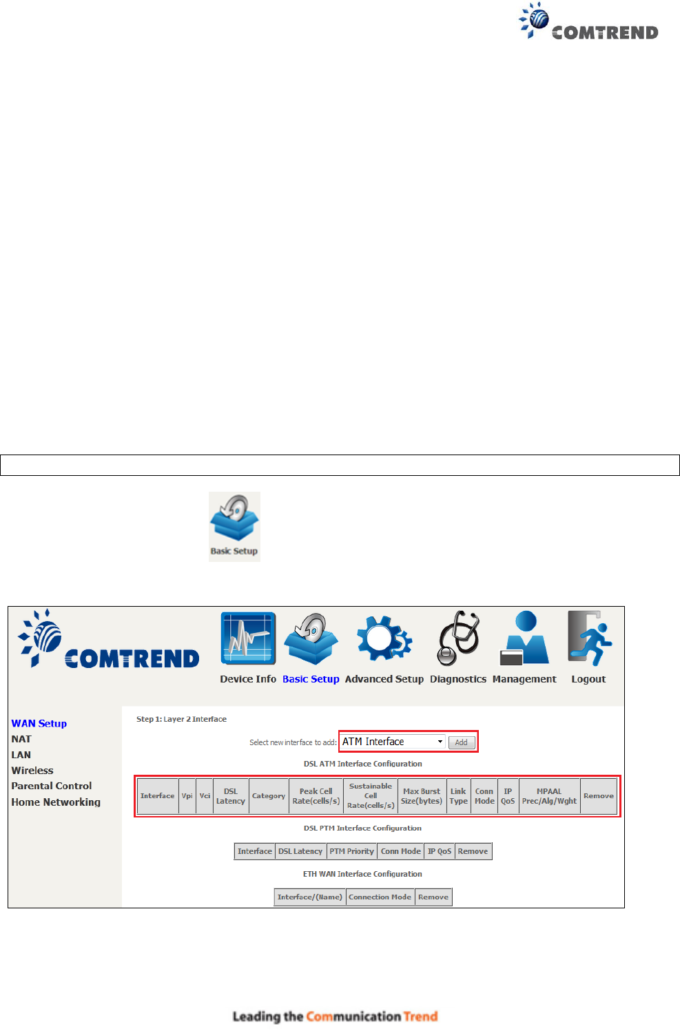
STEP 1: Go to Basic Setup WAN Setup Select ATM Interface from the drop-down
menu.
This table is provided here for ease of reference.

152
Heading
Description
Interface
WAN interface name
VPI
ATM VPI (0-255)
VCI
ATM VCI (32-65535)
DSL Latency
{Path0} portID = 0
Category
ATM service category
Peak Cell Rate
Maximum allowed traffic rate for the ATM PCR service connection
Sustainable Cell
Rate
The average allowable, long-term cell transfer rate on the VBR
service connection
Max Burst Size
The maximum allowable burst size of cells that can be transmitted
contiguously on the VBR service connection
Link Type
Choose EoA (for PPPoE, IPoE, and Bridge), PPPoA, or IPoA.
Connection Mode
Default Mode – Single service over one connection
Vlan Mux Mode – Multiple Vlan service over one connection
IP QoS
Quality of Service (QoS) status
MPAAL
QoS Scheduler algorithm and queue weight defined for the
connection
Remove
Select items for removal
STEP 2: Click Add to proceed to the next screen.
NOTE: To add WAN connections to one interface type, you must delete existing connections
from the other interface type using the remove button.
153
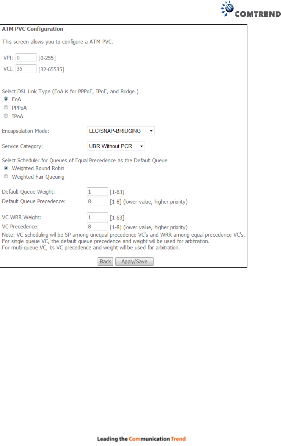
There are many settings here including: VPI/VCI, DSL Link Type, Encapsulation Mode, Service
Category, Connection Mode and Quality of Service.
Here are the available encapsulations for each xDSL Link Type:
EoA- LLC/SNAP-BRIDGING, VC/MUX
PPPoA- VC/MUX, LLC/ENCAPSULATION
IPoA- LLC/SNAP-ROUTING, VC MUX
STEP 3: Click Apply/Save to confirm your choices.
On the next screen, check that the ATM interface is added to the list. For example, an ATM
interface on PVC 0/35 in Default Mode with an EoA Link type is shown below.

155
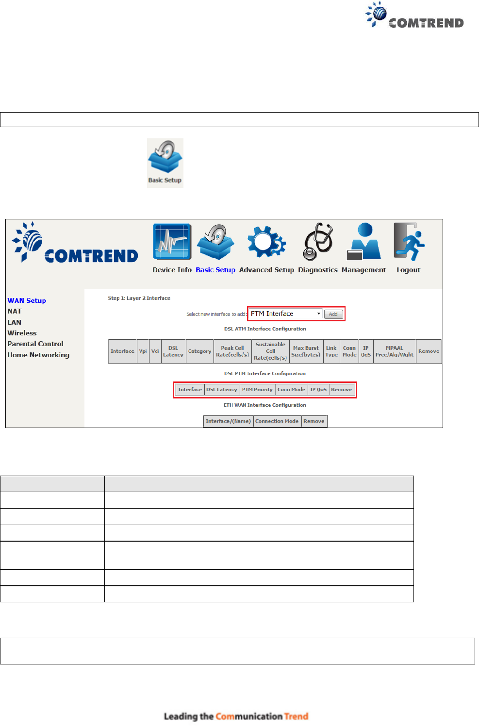
E1.2 PTM Interfaces
Follow these procedures to configure a PTM interface.
NOTE: The AR-5313u supports up to four PTM interfaces.
STEP 1: Go to Basic Setup WAN Setup Select PTM Interface from the drop-down
menu.
This table is provided here for ease of reference.
Heading
Description
Interface
WAN interface name.
DSL Latency
{Path0} portID = 0
PTM Priority
Normal or High Priority (Preemption).
Connection Mode
Default Mode – Single service over one interface.
Vlan Mux Mode – Multiple Vlan services over one interface.
IP QoS
Quality of Service (QoS) status.
Remove
Select interfaces to remove.
STEP 2: Click Add to proceed to the next screen.
NOTE: To add WAN connections to one interface type, you must delete existing connections
from the other interface type using the remove button.
156
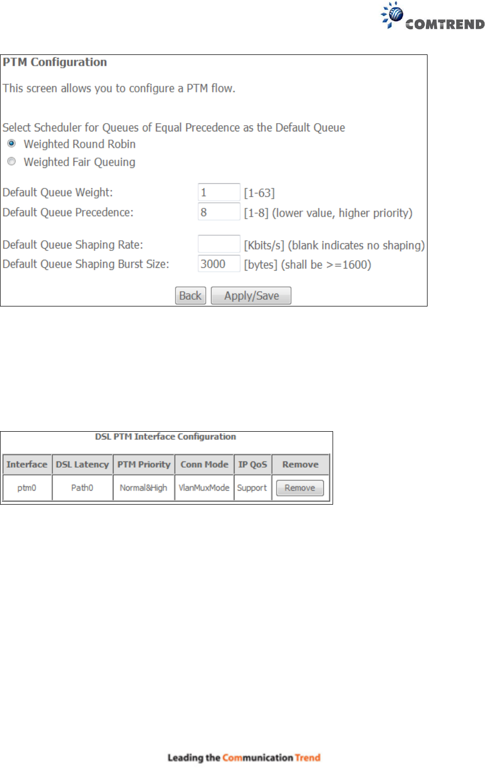
There are many settings that can be configured here including:
PTM Priority, Connection Mode and Quality of Service.
STEP 3: Click Apply/Save to confirm your choices.
On the next screen, check that the PTM interface is added to the list.
For example, an PTM interface in Default Mode is shown below.
To add a WAN connection go to section E2 WAN Connections.
157
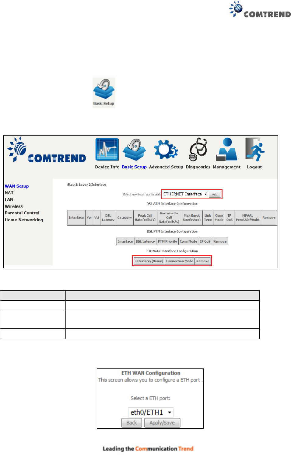
E1.3 ETHERNET Interfaces
Follow these procedures to configure a PTM interface.
STEP 1: Go to Basic Setup WAN Setup Select ETHERNET Interface from the
drop-down menu.
This table is provided here for ease of reference.
Heading
Description
Interface/ (Name)
WAN interface name.
Connection Mode
Default Mode – Single service over one interface.
Vlan Mux Mode – Multiple Vlan services over one interface.
Remove
Select interfaces to remove.
STEP 2: Click Add to proceed to the next screen.
STEP 3: Select an Ethernet port and Click Apply/Save to confirm your choices.
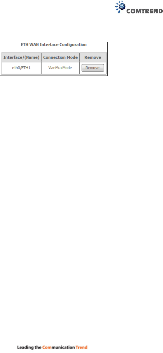
158
On the next screen, check that the ETHERNET interface is added to the list.
159
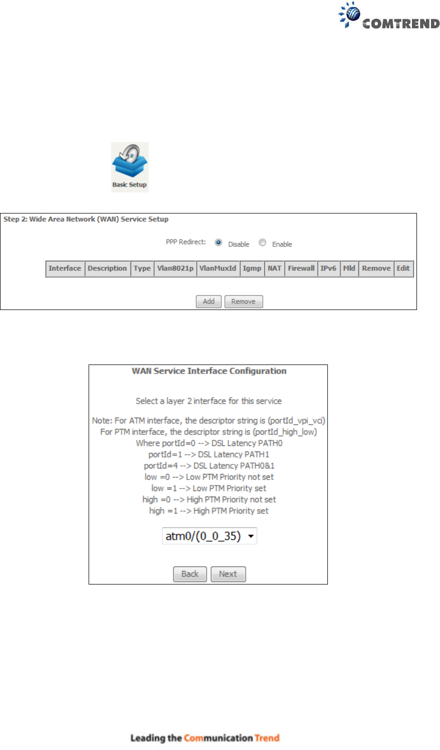
E2 ~ WAN Connections
The AR-5313u supports one WAN connection for each interface, up to a maximum of 16
connections.
To setup a WAN connection follow these instructions.
STEP 1: Go to Basic Setup WAN Setup.
STEP 2: Click Add to create a WAN connection. The following screen will display.
160
STEP 3: Choose a layer 2 interface from the drop-down box and click Next.
The WAN Service Configuration screen will display as shown below.
NOTE: The WAN services shown here are those supported by the layer 2 interface you
selected in the previous step. If you wish to change your selection click the Back
button and select a different layer 2 interface.
STEP 4: For VLAN Mux Connections only, you must enter Priority & VLAN ID tags.
STEP 5: You will now follow the instructions specific to the WAN service type you wish to
establish. This list should help you locate the correct procedure:
(1) E2.1 PPP over ETHERNET (PPPoE) – IPv4
(2) E2.2 IP over ETHERNET (IPoE) – IPv4
(3) E2.3 Bridging – IPv4
(4) E2.4 PPP over ATM (PPPoA) – IPv4
(5) E2.5 IP over ATM (IPoA) – IPv4
(6) E2.6 PPP over ETHERNET (PPPoE) – IPv6
(7) E2.7 IP over ETHERNET (IPoE) – IPv6
(8) Bridging – IPv6 (Not Supported)
(9) E2.8 PPP over ATM (PPPoA) – IPv6
(10) IPoA – IPv6 (Not Supported)
The subsections that follow continue the WAN service setup procedure.
161
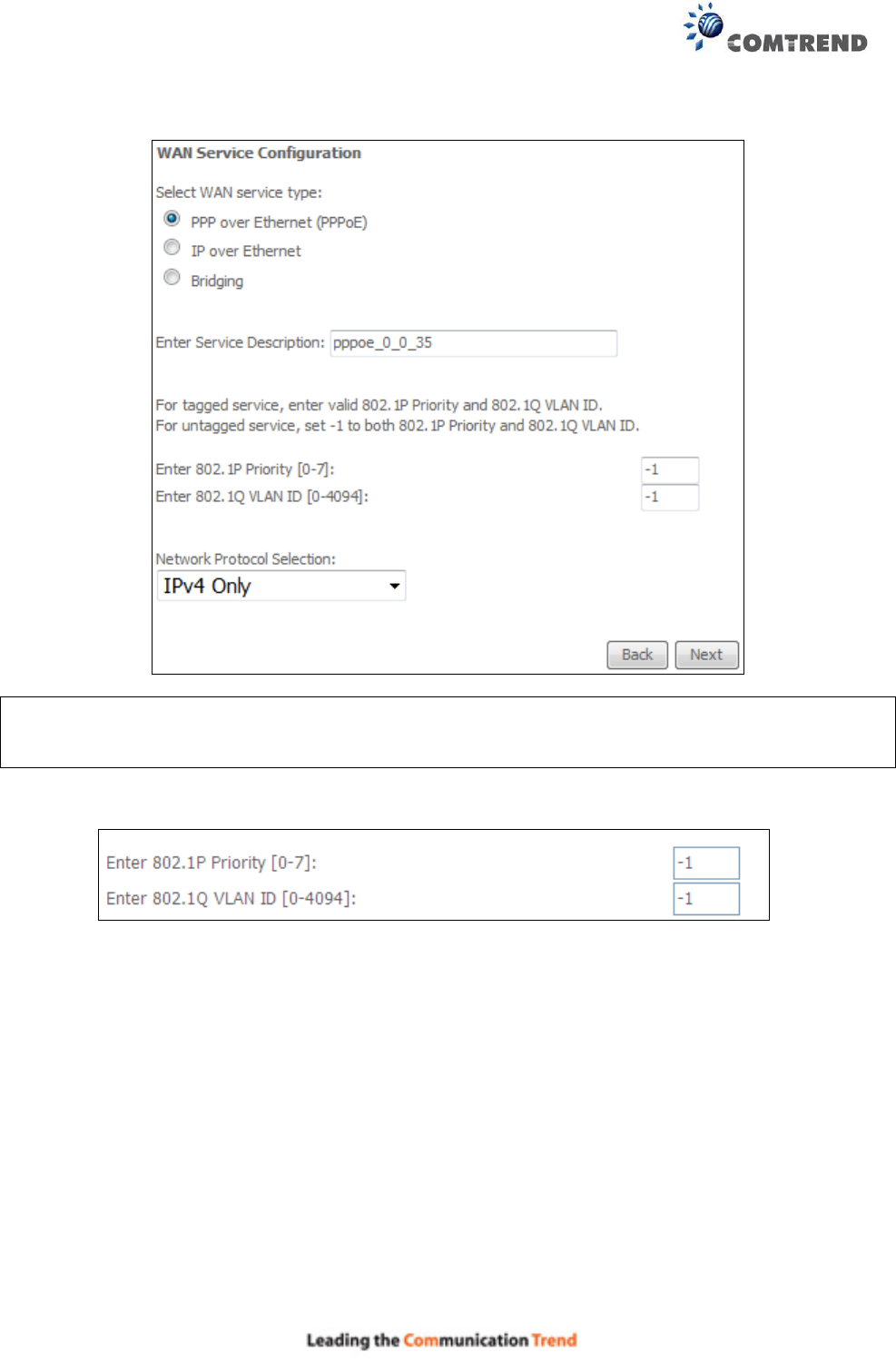
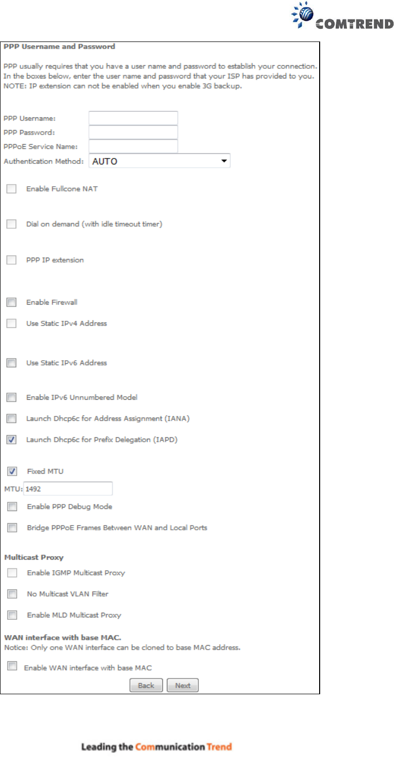
E2.1 PPP over ETHERNET (PPPoE) – IPv4
STEP 1: Select the PPP over Ethernet radio button and click Next. You can also enable IPv6 by
ticking the checkbox at the bottom of this screen.
STEP 2: On the next screen, enter the PPP settings as provided by your ISP.
Click Next to continue or click Back to return to the previous step.
162
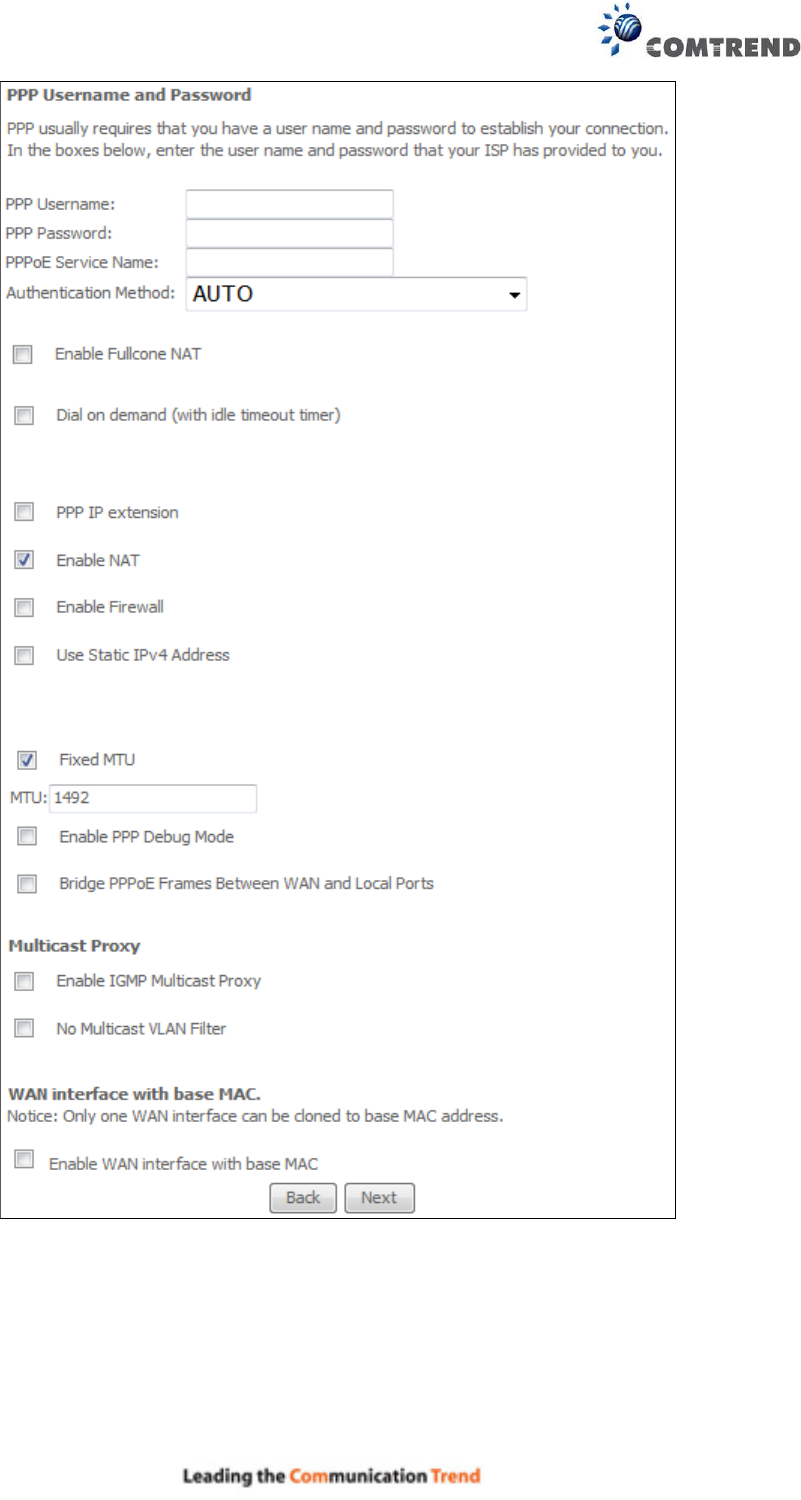
The settings shown above are described below.
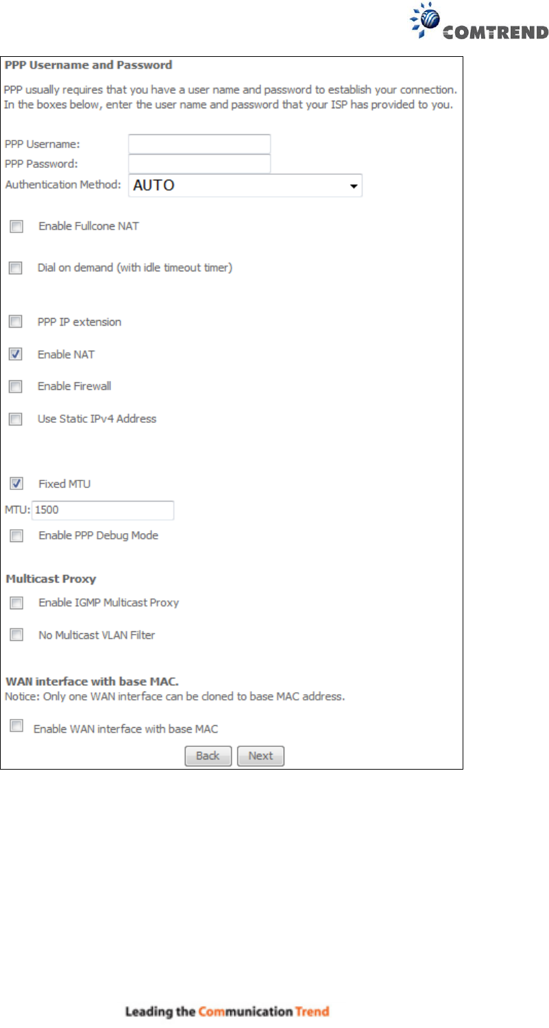
PPP SETTINGS
The PPP Username, PPP password and the PPPoE Service Name entries are dependent on the
particular requirements of the ISP. The user name can be a maximum of 256 characters and the
password a maximum of 32 characters in length. For Authentication Method, choose from AUTO,
PAP, CHAP, and MSCHAP.

163
ENABLE FULLCONE NAT
This option becomes available when NAT is enabled. Known as one-to-one NAT, all requests from
the same internal IP address and port are mapped to the same external IP address and port. An
external host can send a packet to the internal host, by sending a packet to the mapped external
address.
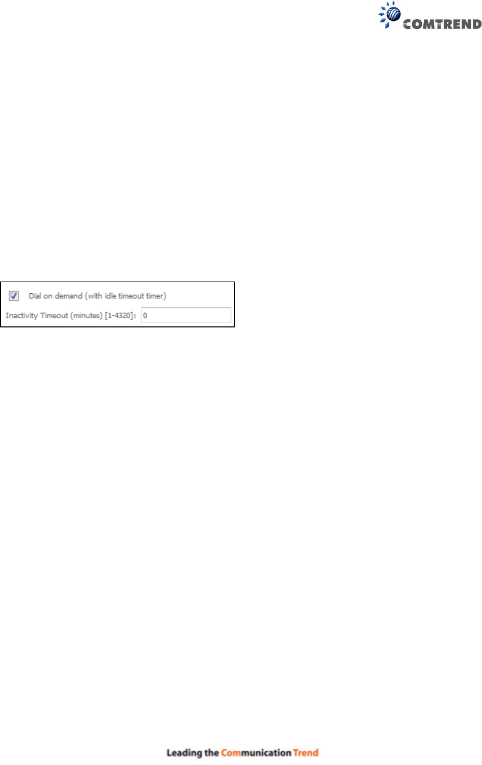
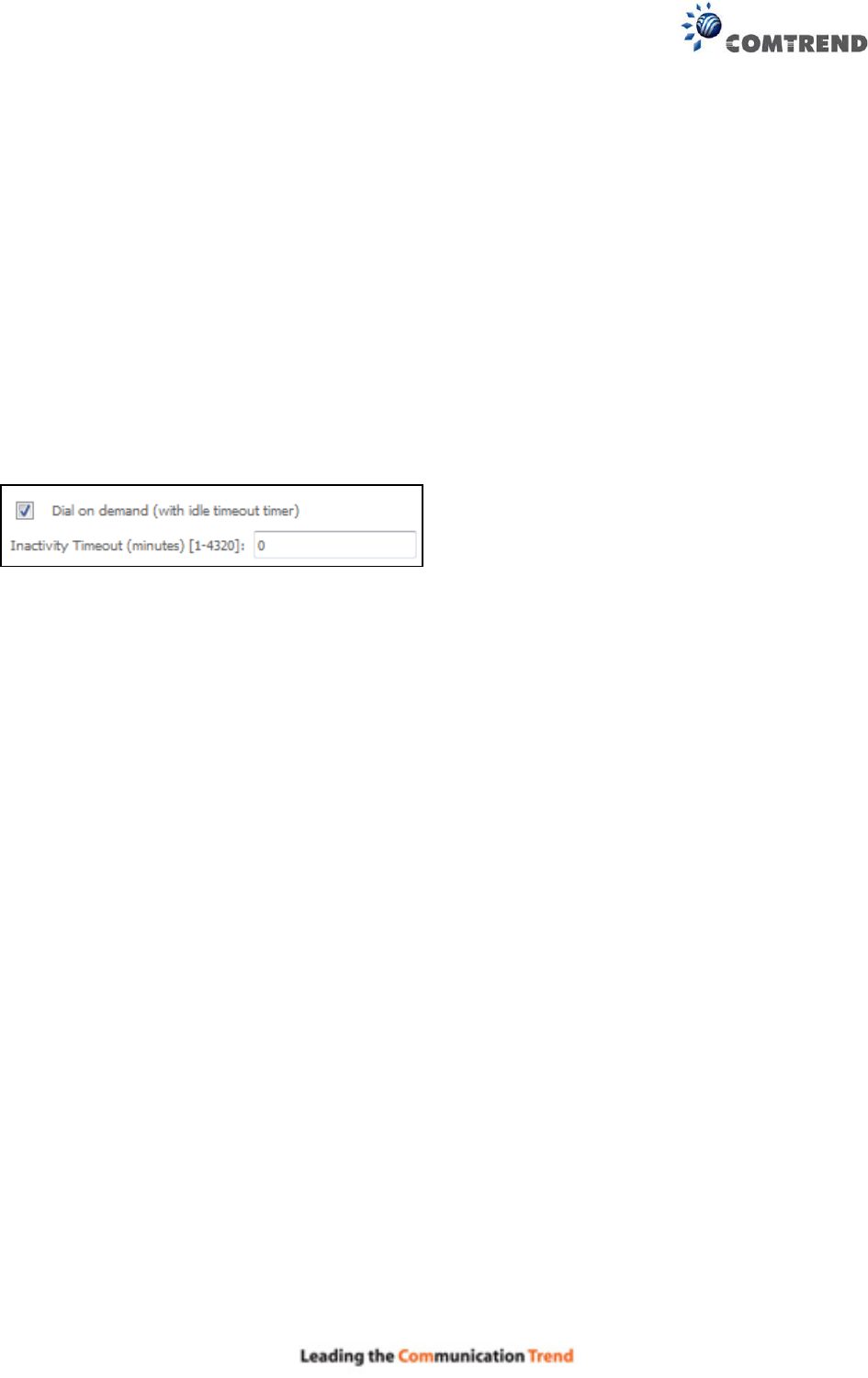
DIAL ON DEMAND
The AR-5313u can be configured to disconnect if there is no activity for a period of time by
selecting the Dial on demand checkbox . You must also enter an inactivity timeout period in
the range of 1 to 4320 minutes.
PPP IP EXTENSION
The PPP IP Extension is a special feature deployed by some service providers. Unless your
service provider specifically requires this setup, do not select it.
PPP IP Extension does the following:
Allows only one PC on the LAN.
Disables NAT and Firewall.
The device becomes the default gateway and DNS server to the PC through DHCP
using the LAN interface IP address.
The device extends the IP subnet at the remote service provider to the LAN PC. i.e.
the PC becomes a host belonging to the same IP subnet.
The device bridges the IP packets between WAN and LAN ports, unless the packet is
addressed to the device’s LAN IP address.
The public IP address assigned by the remote side using the PPP/IPCP protocol is
actually not used on the WAN PPP interface. Instead, it is forwarded to the PC LAN
interface through DHCP. Only one PC on the LAN can be connected to the remote,
since the DHCP server within the device has only a single IP address to assign to a LAN
device.
ENABLE NAT
If the LAN is configured with a private IP address, the user should select this checkbox . The NAT
submenu will appear in the Advanced Setup menu after reboot. On the other hand, if a private
IP address is not used on the LAN side (i.e. the LAN side is using a public IP), this checkbox
should not be selected to free up system resources for better performance.
ENABLE FIREWALL
If this checkbox is selected, the Security submenu will be displayed on the Advanced Setup
menu after reboot. If firewall is not necessary, this checkbox should not be selected to free up
system resources for better performance.
USE STATIC IPv4 ADDRESS
Unless your service provider specially requires it, do not select this checkbox . If selected,
enter the static IP address in the IPv4 Address field.
Don’t forget to adjust the IP configuration to Static IP Mode as described in section 3.2.
164
FIXED MTU
Maximum Transmission Unit. The size (in bytes) of largest protocol data unit which the layer can
pass onwards. This value is 1500 for PPPoA.
ENABLE PPP DEBUG MODE
When this option is selected, the system will put more PPP connection information into the system
log. This is for debugging errors and not for normal usage.
BRIDGE PPPOE FRAMES BETWEEN WAN AND LOCAL PORTS
(This option is hidden when PPP IP Extension is enabled)
When Enabled, this creates local PPPoE connections to the WAN side. Enable this option only if all
LAN-side devices are running PPPoE clients, otherwise disable it. The AR-5313u supports
pass-through PPPoE sessions from the LAN side while simultaneously running a PPPoE client from
non-PPPoE LAN devices.
ENABLE IGMP MULTICAST PROXY
Tick the checkbox to enable Internet Group Membership Protocol (IGMP) multicast. This
protocol is used by IPv4 hosts to report their multicast group memberships to any neighboring
multicast routers.
NO MULTICAST VLAN FILTER
Tick the checkbox to Enable/Disable multicast VLAN filter.
Enable WAN interface with base MAC
Enable this option to use the router’s base MAC address as the MAC address for this WAN
interface.
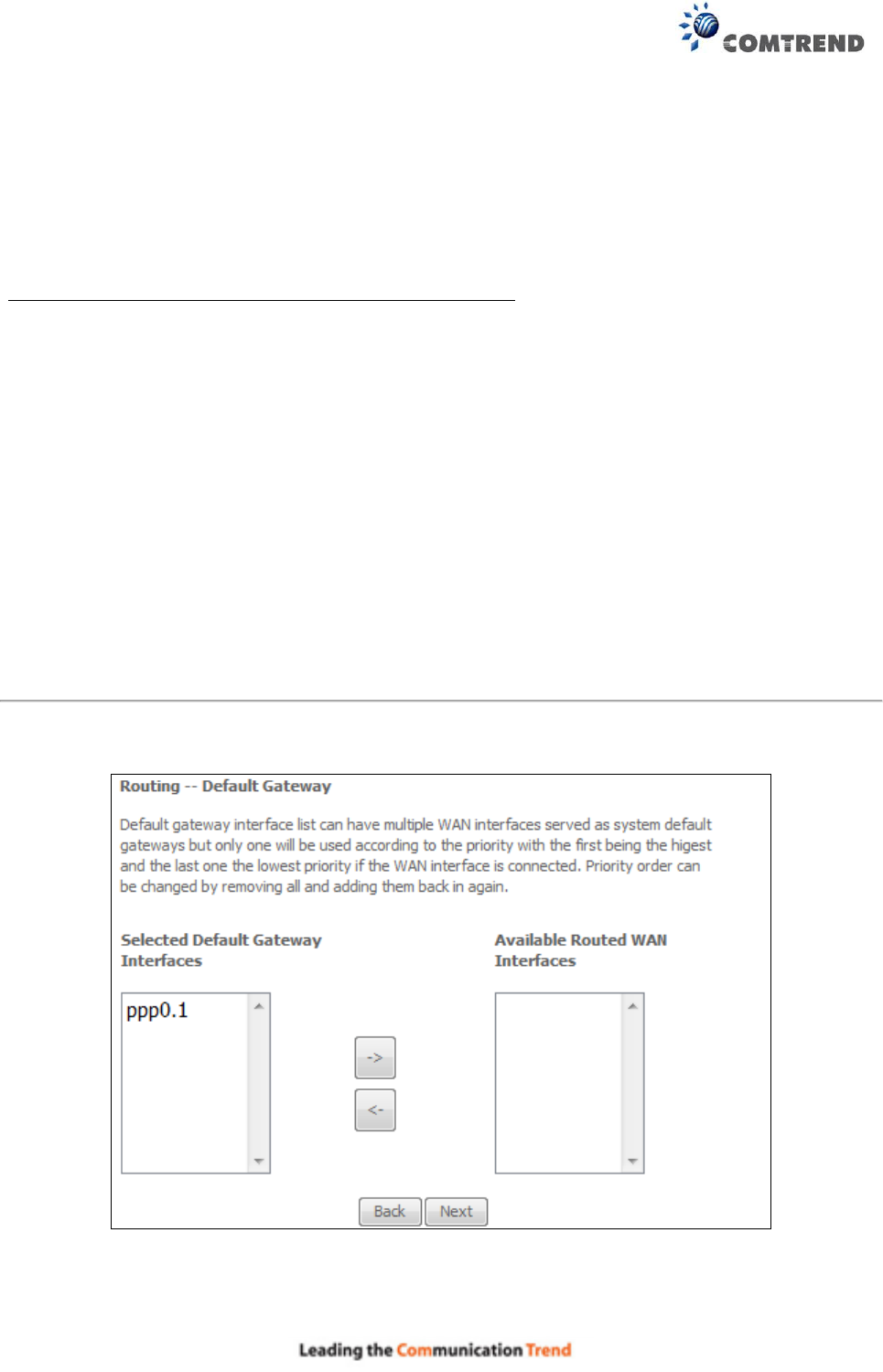
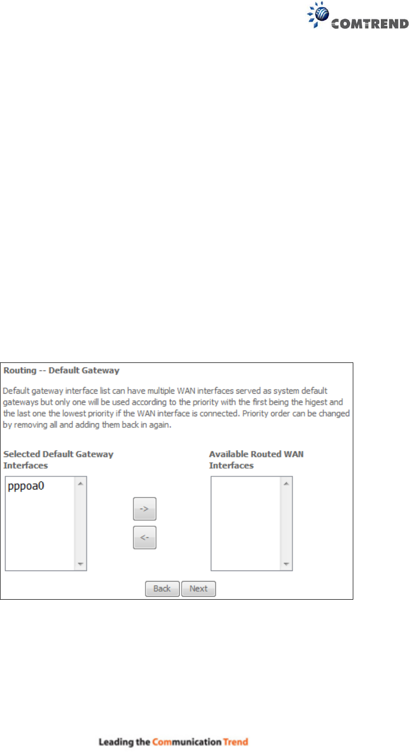
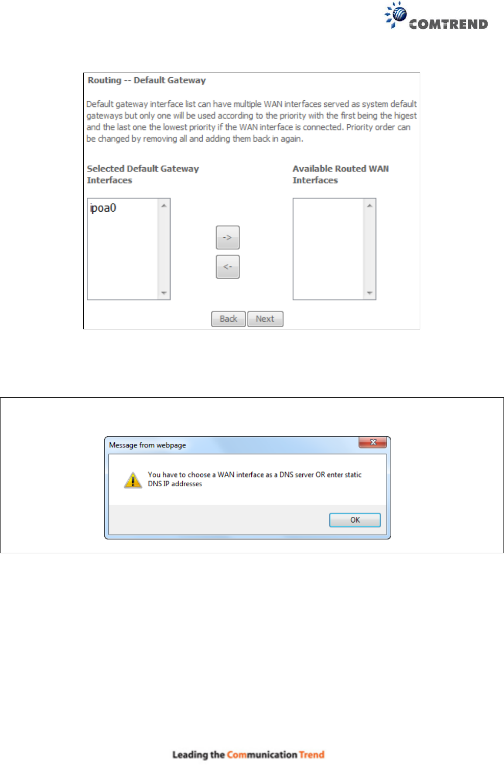
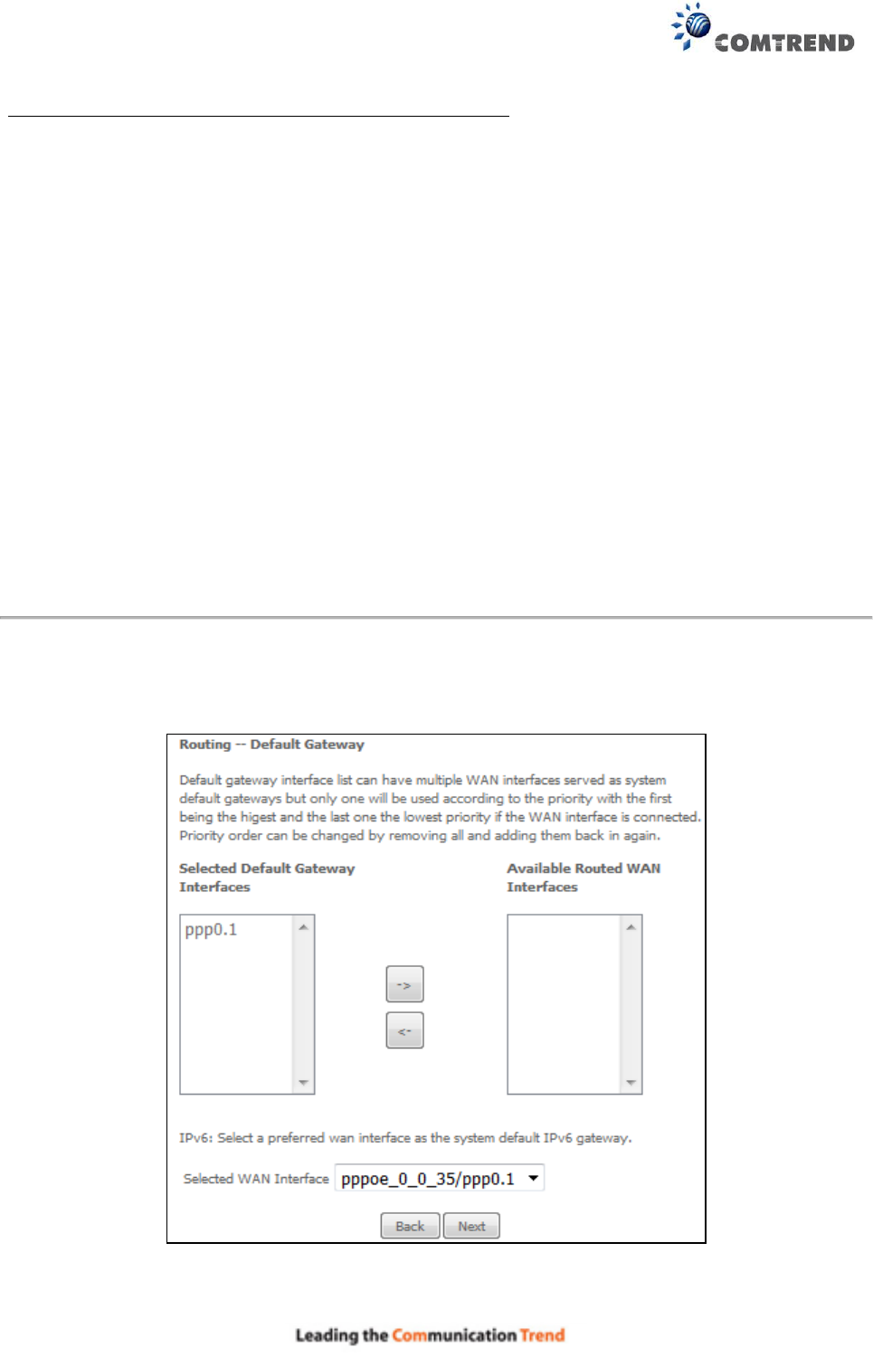
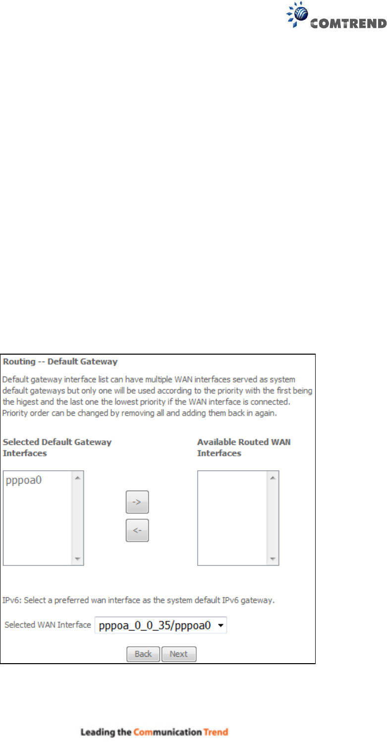
STEP 3: Choose an interface to be the default gateway.
Click Next to continue or click Back to return to the previous step.
165
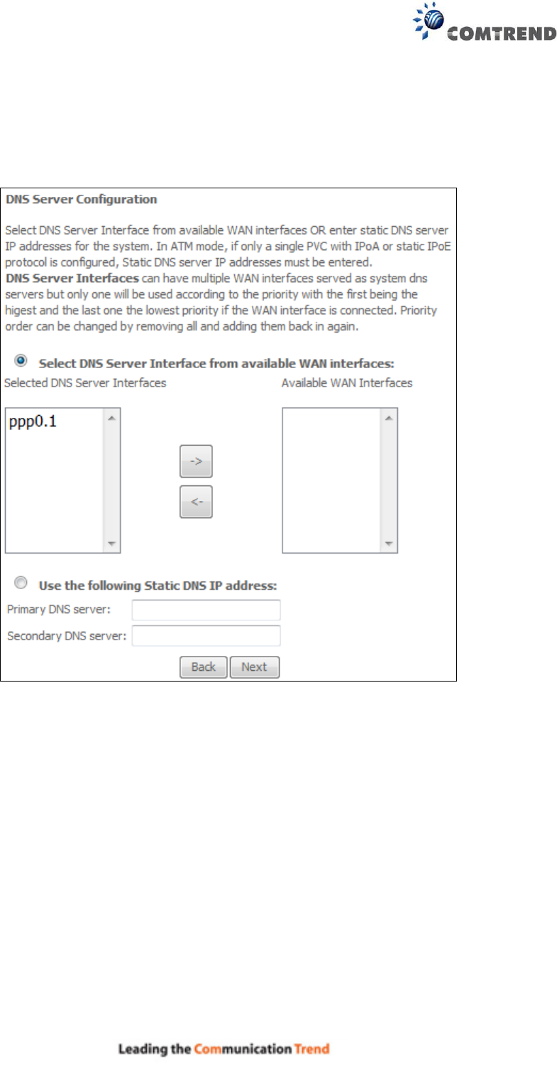
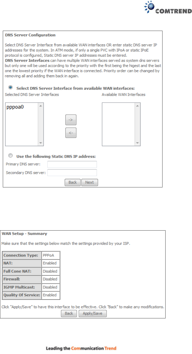
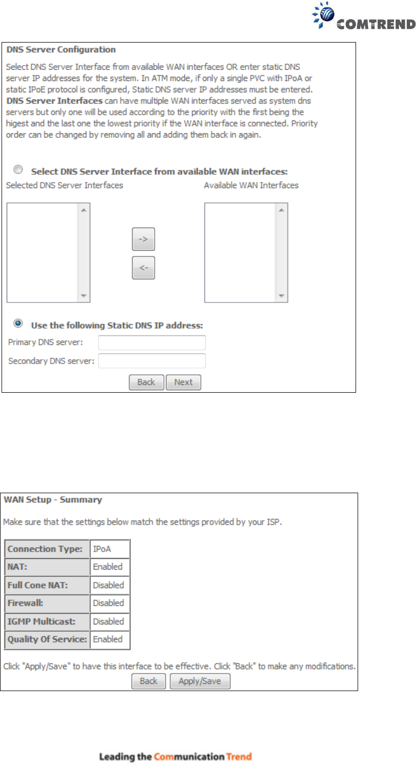
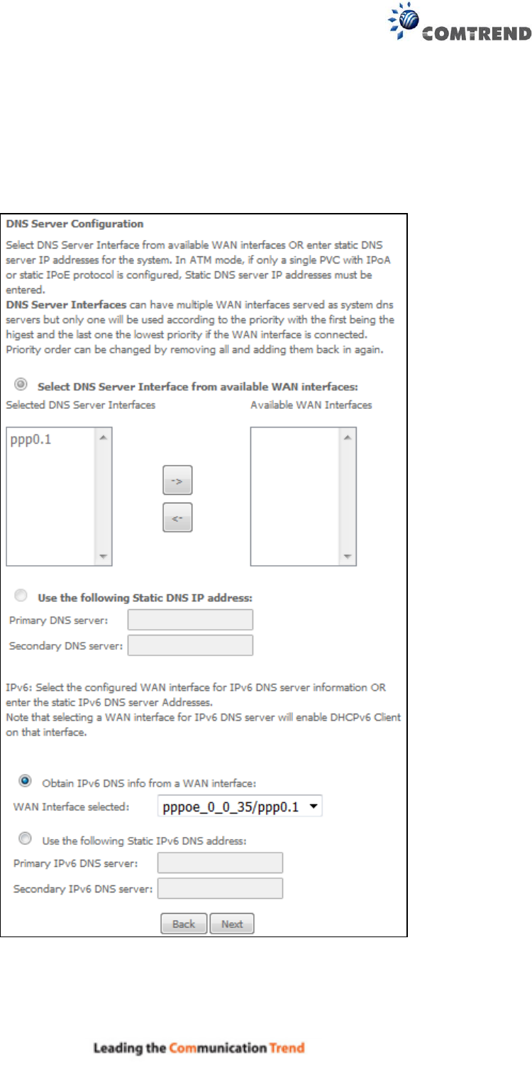
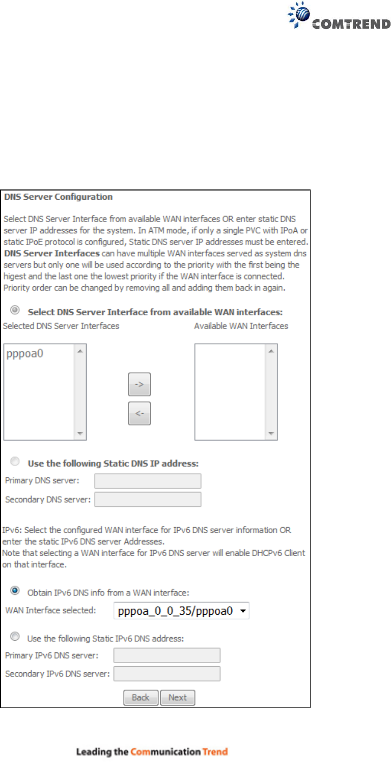
Select DNS Server Interface from available WAN interfaces OR enter static DNS server IP
addresses for the system. In ATM mode, if only a single PVC with IPoA or static IPoE protocol is
configured, Static DNS server IP addresses must be entered.
Click Next to continue or click Back to return to the previous step.
166
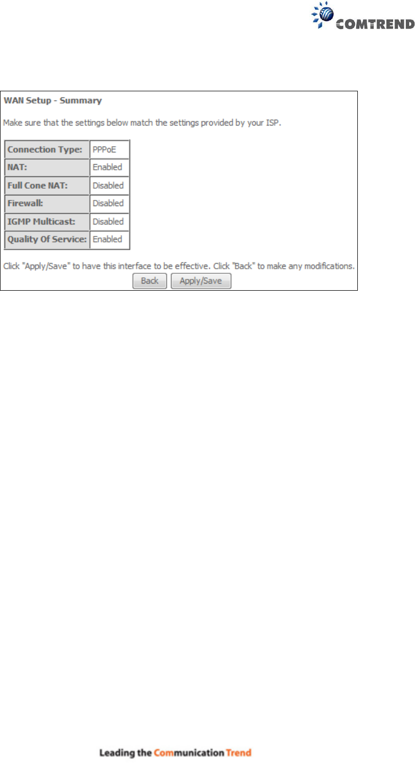
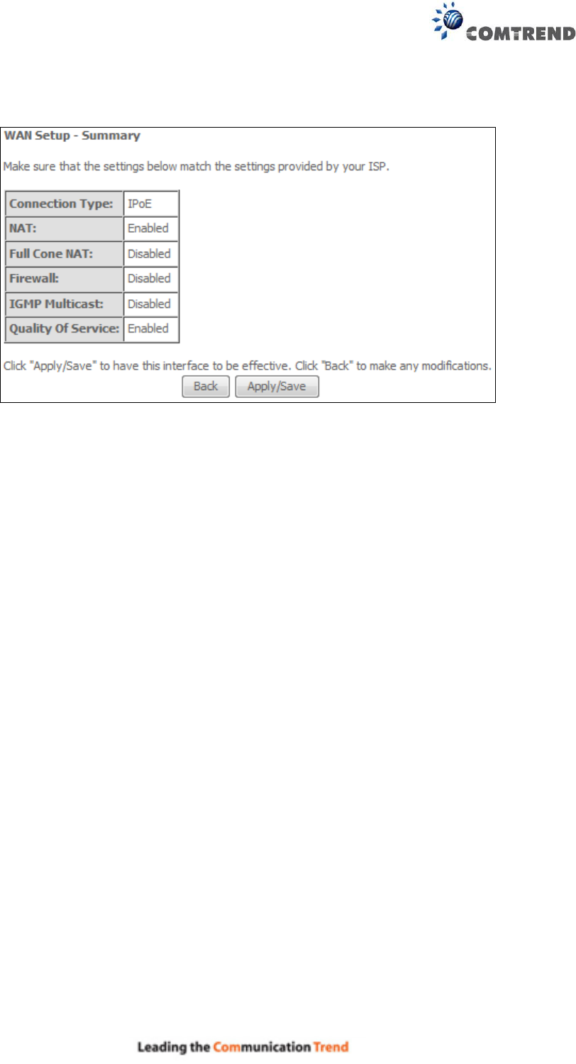
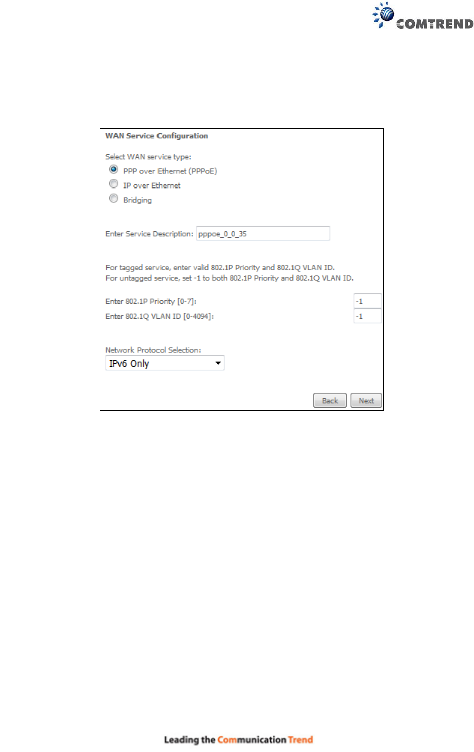
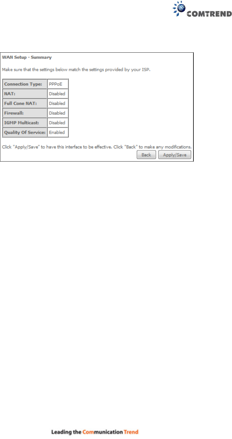
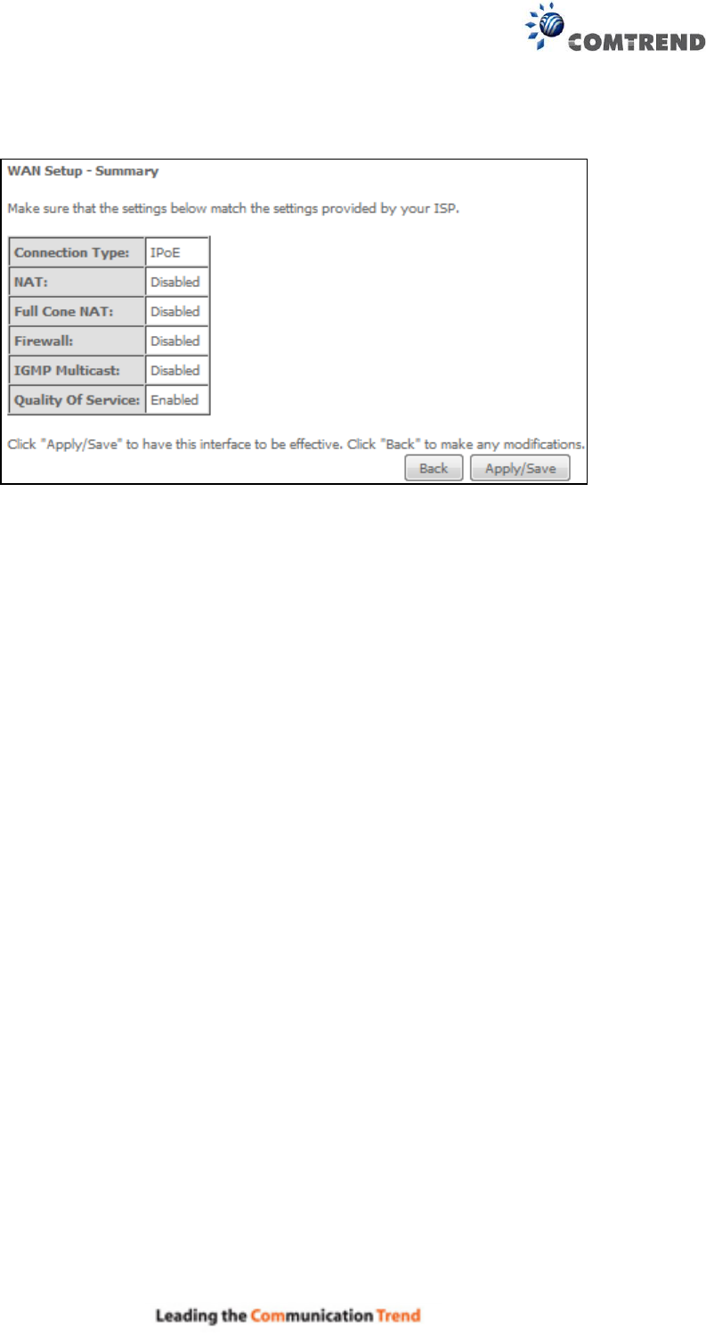
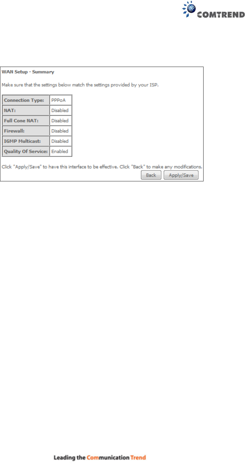
STEP 5: The WAN Setup - Summary screen shows a preview of the WAN service you have
configured. Check these settings and click Apply/Save if they are correct, or click
Back to modify them.
After clicking Apply/Save, the new service should appear on the main screen.
To activate it you must reboot. Go to Management Reboot and click Reboot.
167
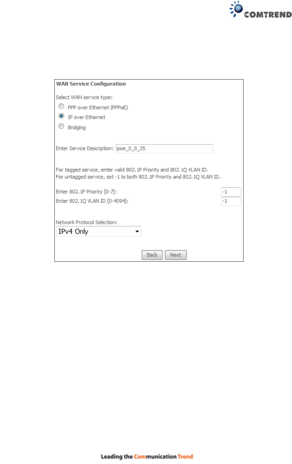
E2.2 IP over ETHERNET (IPoE) – IPv4
STEP 1: Select the IP over Ethernet radio button and click Next.
For tagged service, enter valid 802.1P Priority and 802.1Q VLAN ID.
For untagged service, set -1 to both 802.1P Priority and 802.1Q VLAN ID.
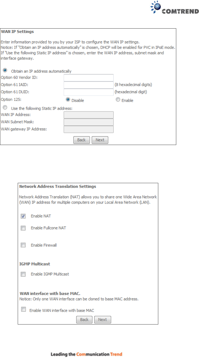
STEP 2: The WAN IP settings screen provides access to the DHCP server settings.
You can select the Obtain an IP address automatically radio button to enable DHCP
(use the DHCP Options only if necessary). However, if you prefer, you can instead use
the Static IP address method to assign WAN IP address, Subnet Mask and Default
Gateway manually.
168
Click Next to continue or click Back to return to the previous step.
STEP 3: This screen provides access to NAT, Firewall and IGMP Multicast settings. Enable each
by selecting the appropriate checkbox . Click Next to continue or click Back to return
to the previous step.
169
ENABLE NAT
If the LAN is configured with a private IP address, the user should select this checkbox . The
NAT submenu will appear in the Advanced Setup menu after reboot. On the other hand, if a
private IP address is not used on the LAN side (i.e. the LAN side is using a public IP), this checkbox
should not be selected, so as to free up system resources for improved performance.
ENABLE FULLCONE NAT
This option becomes available when NAT is enabled. Known as one-to-one NAT, all requests from
the same internal IP address and port are mapped to the same external IP address and port. An
external host can send a packet to the internal host, by sending a packet to the mapped external
address.
ENABLE FIREWALL
If this checkbox is selected, the Security submenu will be displayed on the Advanced Setup
menu after reboot. If firewall is not necessary, this checkbox should not be selected so as to
free up system resources for better performance.
ENABLE IGMP MULTICAST
Tick the checkbox to enable Internet Group Membership Protocol (IGMP) multicast. IGMP is a
protocol used by IPv4 hosts to report their multicast group memberships to any neighboring
multicast routers.
Enable WAN interface with base MAC
Enable this option to use the router’s base MAC address as the MAC address for this WAN
interface.
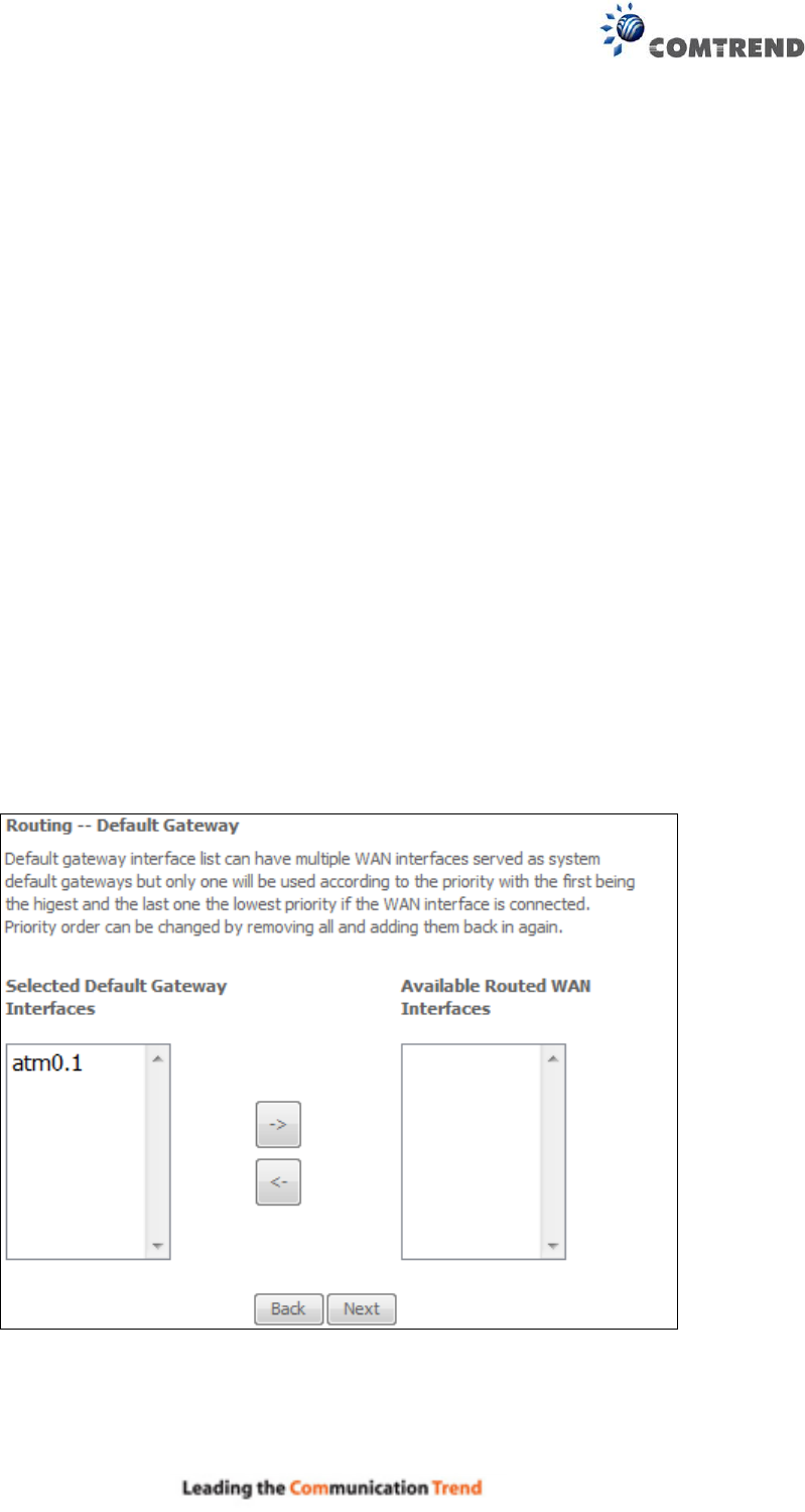
STEP 4: To choose an interface to be the default gateway.
Click Next to continue or click Back to return to the previous step.
170
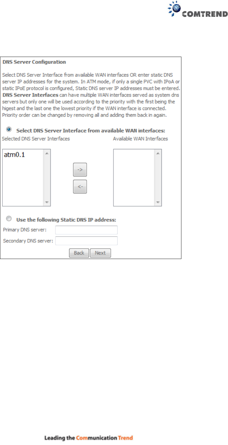
STEP 5: Select DNS Server Interface from available WAN interfaces OR enter static DNS server
IP addresses for the system. In ATM mode, if only a single PVC with IPoA or static IPoE protocol
is configured, Static DNS server IP addresses must be entered.
Click Next to continue or click Back to return to the previous step.
171
STEP 6: The WAN Setup - Summary screen shows a preview of the WAN service you have
configured. Check these settings and click Apply/Save if they are correct, or click
Back to modify them.
After clicking Apply/Save, the new service should appear on the main screen.
To activate it you must reboot. Go to Management Reboot and click Reboot.
172
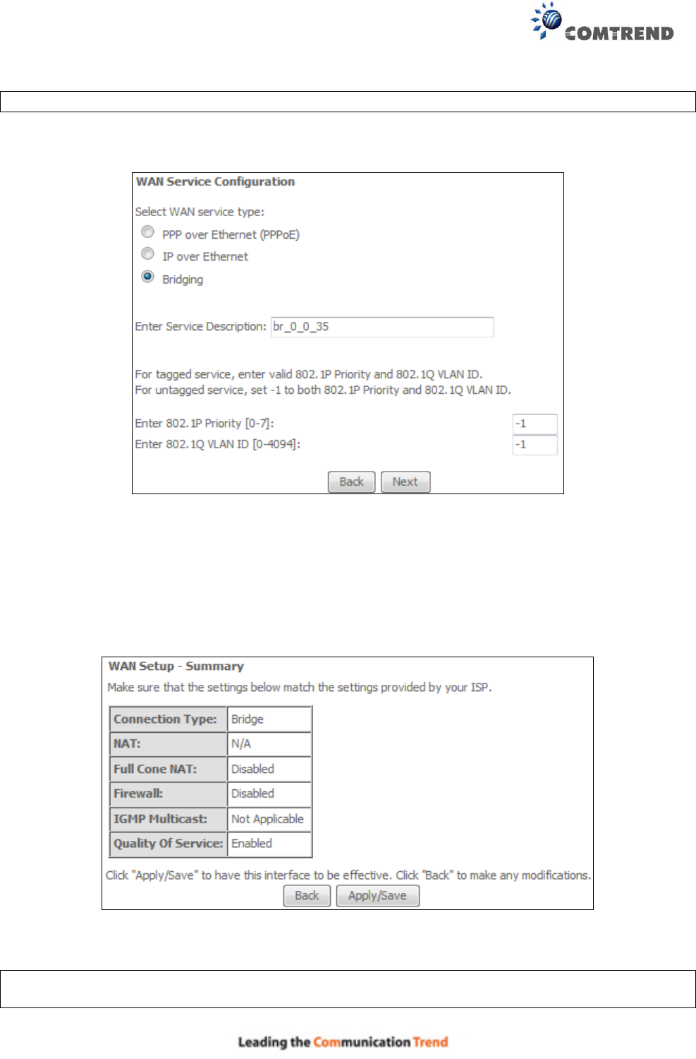
E2.3 Bridging – IPv4
NOTE: This connection type is not available on the Ethernet WAN interface.
STEP 1: Select the Bridging radio button and click Next.
For tagged service, enter valid 802.1P Priority and 802.1Q VLAN ID.
For untagged service, set -1 to both 802.1P Priority and 802.1Q VLAN ID.
STEP 2: The WAN Setup - Summary screen shows a preview of the WAN service you have
configured. Check these settings and click Apply/Save if they are correct, or click
Back to return to the previous screen.
After clicking Apply/Save, the new service should appear on the main screen.
To activate it you must reboot. Go to Management Reboot and click Reboot.
NOTE: If this bridge connection is your only WAN service, the AR-5313u will be inaccessible for
remote management or technical support from the WAN.
173
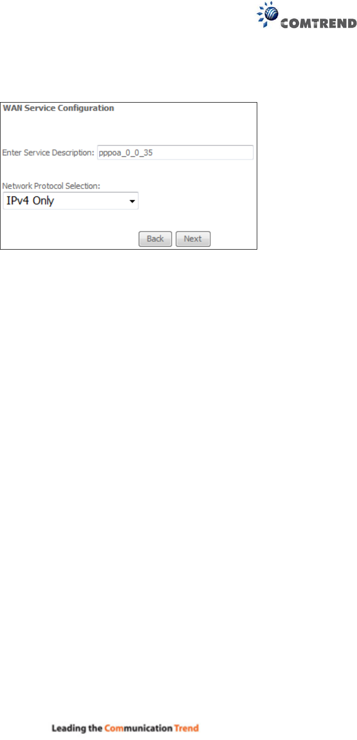
E2.4 PPP over ATM (PPPoA) – IPv4
STEP 1: Click Next to continue.
STEP 2: On the next screen, enter the PPP settings as provided by your ISP.
Click Next to continue or click Back to return to the previous step.
174
PPP SETTINGS
The PPP username and password are dependent on the requirements of the ISP. The user name
can be a maximum of 256 characters and the password a maximum of 32 characters in length.
(Authentication Method: AUTO, PAP, CHAP, or MSCHAP.)
KEEP ALIVE INTERVAL
This option configures the interval between each PPP LCP request and the amount of time to wait
for the PPP server to reply to the LCP request. If the time expired on all requests, the current PPP
session would be dropped.

175
ENABLE FULLCONE NAT
This option becomes available when NAT is enabled. Known as one-to-one NAT, all requests from
the same internal IP address and port are mapped to the same external IP address and port. An
external host can send a packet to the internal host, by sending a packet to the mapped external
address.
DIAL ON DEMAND
The AR-5313u can be configured to disconnect if there is no activity for a period of time by
selecting the Dial on demand checkbox . You must also enter an inactivity timeout period in
the range of 1 to 4320 minutes.
PPP IP EXTENSION
The PPP IP Extension is a special feature deployed by some service providers. Unless your
service provider specifically requires this setup, do not select it.
PPP IP Extension does the following:
Allows only one PC on the LAN.
Disables NAT and Firewall.
The device becomes the default gateway and DNS server to the PC through DHCP
using the LAN interface IP address.
The device extends the IP subnet at the remote service provider to the LAN PC. i.e.
the PC becomes a host belonging to the same IP subnet.
The device bridges the IP packets between WAN and LAN ports, unless the packet is
addressed to the device’s LAN IP address.
The public IP address assigned by the remote side using the PPP/IPCP protocol is
actually not used on the WAN PPP interface. Instead, it is forwarded to the PC LAN
interface through DHCP. Only one PC on the LAN can be connected to the remote,
since the DHCP server within the device has only a single IP address to assign to a LAN
device.
ENABLE NAT
If the LAN is configured with a private IP address, the user should select this checkbox . The NAT
submenu will appear in the Advanced Setup menu after reboot. On the other hand, if a private
IP address is not used on the LAN side (i.e. the LAN side is using a public IP), this checkbox
should not be selected to free up system resources for better performance.
ENABLE FIREWALL
If this checkbox is selected, the Security submenu will be displayed on the Advanced Setup
menu after reboot. If firewall is not necessary, this checkbox should not be selected to free up
system resources for better performance.
USE STATIC IPv4 ADDRESS
Unless your service provider specially requires it, do not select this checkbox . If selected,
enter the static IP address in the IP Address field. Also, don’t forget to adjust the IP
configuration to Static IP Mode as described in section 3.2.
176
Fixed MTU
Fixed Maximum Transmission Unit. The size (in bytes) of largest protocol data unit which the layer
can pass onwards. This value is 1500 for PPPoA.
ENABLE PPP DEBUG MODE
When this option is selected, the system will put more PPP connection information into the system
log. This is for debugging errors and not for normal usage.
ENABLE IGMP MULTICAST PROXY
Tick the checkbox to enable Internet Group Membership Protocol (IGMP) multicast. This
protocol is used by IPv4 hosts to report their multicast group memberships to any neighboring
multicast routers.
NO MULTICAST VLAN FILTER
Tick the checkbox to Enable/Disable multicast VLAN filter.
Enable WAN interface with base MAC
Enable this option to use the router’s base MAC address as the MAC address for this WAN
interface.
STEP 3: Choose an interface to be the default gateway.
Click Next to continue or click Back to return to the previous step.
177
STEP 4: Choose an interface to be the default gateway.
Click Next to continue or click Back to return to the previous step.
STEP 5: The WAN Setup - Summary screen shows a preview of the WAN service you have
configured. Check these settings and click Apply/Save if they are correct, or click Back to
modify them.
After clicking Apply/Save, the new service should appear on the main screen.
To activate it you must reboot. Go to Management Reboot and click Reboot.
178
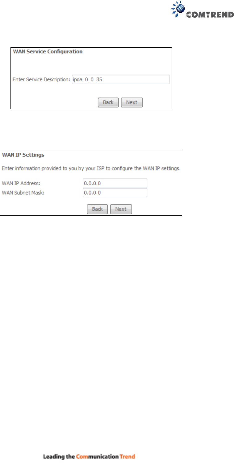
E2.5 IP over ATM (IPoA) – IPv4
STEP 1: Click Next to continue.
STEP 2: Enter the WAN IP settings provided by your ISP. Click Next to continue.
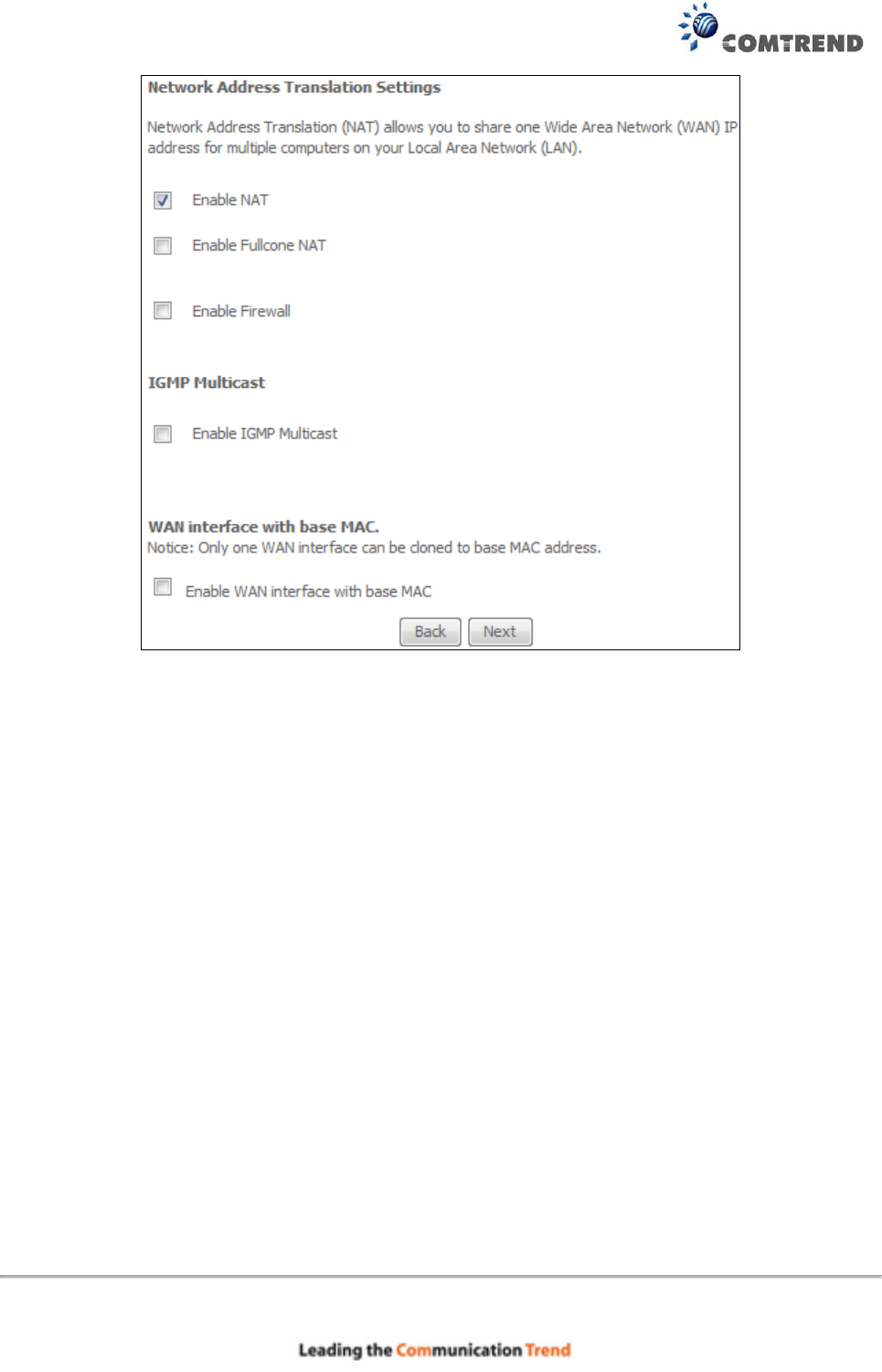
STEP 3: This screen provides access to NAT, Firewall and IGMP Multicast settings. Enable each
by selecting the appropriate checkbox . Click Next to continue or click Back to return
to the previous step.
179
ENABLE NAT
If the LAN is configured with a private IP address, the user should select this checkbox . The
NAT submenu will appear in the Advanced Setup menu after reboot. On the other hand, if a
private IP address is not used on the LAN side (i.e. the LAN side is using a public IP), this checkbox
should not be selected, so as to free up system resources for improved performance.
ENABLE FULLCONE NAT
This option becomes available when NAT is enabled. Known as one-to-one NAT, all requests from
the same internal IP address and port are mapped to the same external IP address and port. An
external host can send a packet to the internal host by sending a packet to the mapped external
address.
ENABLE FIREWALL
If this checkbox is selected, the Security submenu will be displayed on the Advanced Setup
menu after reboot. If firewall is not necessary, this checkbox should not be selected so as to
free up system resources for better performance.
ENABLE IGMP MULTICAST
Tick the checkbox to enable Internet Group Membership Protocol (IGMP) multicast. IGMP is a
protocol used by IPv4 hosts to report their multicast group memberships to any neighboring
multicast routers.
Enable WAN interface with base MAC
Enable this option to use the router’s base MAC address as the MAC address for this WAN
interface.
180
STEP 4: Choose an interface to be the default gateway.
Click Next to continue or click Back to return to the previous step.
NOTE: If the DHCP server is not enabled on another WAN interface then the following
notification will be shown before the next screen.
STEP 5: Choose an interface to be the default gateway.
181
Click Next to continue or click Back to return to the previous step.
STEP 6: The WAN Setup - Summary screen shows a preview of the WAN service you have
configured. Check these settings and click Apply/Save if they are correct, or click
Back to modify them.
After clicking Apply/Save, the new service should appear on the main screen.
To activate it you must reboot. Go to Management Reboot and click Reboot.
182
E2.6 PPP over ETHERNET (PPPoE) – IPv6
STEP 1: Select the PPP over Ethernet radio button. Then select IPv6 only from the drop-down
box at the bottom off the screen and click Next.
For tagged service, enter valid 802.1P Priority and 802.1Q VLAN ID.
For untagged service, set -1 to both 802.1P Priority and 802.1Q VLAN ID.
STEP 2: On the next screen, enter the PPP settings as provided by your ISP.
183
Click Next to continue or click Back to return to the previous step.
184
The settings shown above are described below.
PPP SETTINGS
The PPP Username, PPP password and the PPPoE Service Name entries are dependent on the
particular requirements of the ISP. The user name can be a maximum of 256 characters and the
password a maximum of 32 characters in length. For Authentication Method, choose from AUTO,
PAP, CHAP, and MSCHAP.
ENABLE FULLCONE NAT
This option becomes available when NAT is enabled. Known as one-to-one NAT, all requests from
the same internal IP address and port are mapped to the same external IP address and port. An
external host can send a packet to the internal host, by sending a packet to the mapped external
address.
DIAL ON DEMAND
The AR-5313u can be configured to disconnect if there is no activity for a period of time by
selecting the Dial on demand checkbox . You must also enter an inactivity timeout period in
the range of 1 to 4320 minutes.
PPP IP EXTENSION
The PPP IP Extension is a special feature deployed by some service providers. Unless your
service provider specifically requires this setup, do not select it.
PPP IP Extension does the following:
Allows only one PC on the LAN.
Disables NAT and Firewall.
The device becomes the default gateway and DNS server to the PC through DHCP
using the LAN interface IP address.
The device extends the IP subnet at the remote service provider to the LAN PC. i.e.
the PC becomes a host belonging to the same IP subnet.
The device bridges the IP packets between WAN and LAN ports, unless the packet is
addressed to the device’s LAN IP address.
The public IP address assigned by the remote side using the PPP/IPCP protocol is
actually not used on the WAN PPP interface. Instead, it is forwarded to the PC LAN
interface through DHCP. Only one PC on the LAN can be connected to the remote,
since the DHCP server within the device has only a single IP address to assign to a LAN
device.
ENABLE FIREWALL
If this checkbox is selected, the Security submenu will be displayed on the Advanced Setup
menu after reboot. If firewall is not necessary, this checkbox should not be selected to free up
system resources for better performance.
USE STATIC IPv4 ADDRESS
Unless your service provider specially requires it, do not select this checkbox . If selected,
enter the static IP address in the IPv4 Address field.
Don’t forget to adjust the IP configuration to Static IP Mode as described in section 3.2 IP
Configuration.

185
USE STATIC IPv6 ADDRESS
Unless your service provider specially requires it, do not select this checkbox . If selected,
enter the static IP address in the IPv6 Address field.
Don’t forget to adjust the IP configuration to Static IP Mode as described in section 3.2 IP
Configuration.
ENABLE IPv6 UNNUMBERED MODEL
The IP unnumbered configuration command allows you to enable IP processing on a serial
interface without assigning it an explicit IP address. The IP unnumbered interface can "borrow"
the IP address of another interface already configured on the router, which conserves network
and address space.
LAUNCH DHCP6C FOR ADDRESS ASSIGNMENT (IANA)
The Internet Assigned Numbers Authority (IANA) is a department of ICANN responsible for
coordinating some of the key elements that keep the Internet running smoothly. Whilst the
Internet is renowned for being a worldwide network free from central coordination, there is a
technical need for some key parts of the Internet to be globally coordinated, and this coordination
role is undertaken by IANA.
Specifically, IANA allocates and maintains unique codes and numbering systems that are used in
the technical standards (“protocols”) that drive the Internet.
IANA’s various activities can be broadly grouped in to three categories:
• Domain Names
IANA manages the DNS Root, the .int and .arpa domains, and an IDN practices resource.
• Number Resources
IANA coordinates the global pool of IP and AS numbers, providing them to
Regional Internet Registries.
• Protocol Assignments
Internet protocols’ numbering systems are managed by IANA in conjunction
with standards bodies.
LAUNCH DHCP6C FOR PREFIX DELEGATION (IAPD)
An Identity Association for Prefix Delegation (IAPD) is a collection of prefixes assigned to a
requesting device. A requesting device may have more than one IAPD; for example, one for each
of its interfaces.
A prefix-delegating router (DHCPv6 server) selects prefixes to be assigned to a requesting router
(DHCPv6 client) upon receiving a request from the client. The server can select prefixes for a
requesting client by using static and dynamic assignment mechanisms. Administrators can
manually configure a list of prefixes and associated preferred and valid lifetimes for an IAPD of a
specific client that is identified by its DUID.
When the delegating router receives a request from a client, it checks if there is a static binding
configured for the IAPD in the client’s message. If a static binding is present, the prefixes in the
binding are returned to the client. If no such binding is found, the server attempts to assign
prefixes for the client from other sources.
An IPv6 prefix delegating router can also select prefixes for a requesting router based on an
external authority such as a RADIUS server using the Framed-IPv6-Prefix attribute.
FIXED MTU
Maximum Transmission Unit. The size (in bytes) of largest protocol data unit which the layer can
pass onwards. This value is 1492 for PPPoE.
ENABLE PPP DEBUG MODE
When this option is selected, the system will put more PPP connection information into the system
log. This is for debugging errors and not for normal usage.
186
BRIDGE PPPOE FRAMES BETWEEN WAN AND LOCAL PORTS
(This option is hidden when PPP IP Extension is enabled)
When Enabled, this creates local PPPoE connections to the WAN side. Enable this option only if all
LAN-side devices are running PPPoE clients, otherwise disable it. The AR-5313u supports
pass-through PPPoE sessions from the LAN side while simultaneously running a PPPoE client from
non-PPPoE LAN devices.
Enable IGMP Multicast Proxy
Tick the checkbox to enable Internet Group Membership Protocol (IGMP) multicast. This
protocol is used by IPv6 hosts to report their multicast group memberships to any neighboring
multicast routers.
No Multicast VLAN Filter
Tick the checkbox to Enable/Disable multicast VLAN filter.
ENABLE MLD MULTICAST PROXY
Multicast Listener Discovery (MLD) is a component of the Internet Protocol Version 6 (IPv6) suite.
MLD is used by IPv6 routers for discovering multicast listeners on a directly attached link, much
like IGMP is used in IPv4. The protocol is embedded in ICMPv6 instead of using a separate
protocol.
WAN interface with base MAC
Enable this option to use the router’s base MAC address as the MAC address for this WAN
interface.
STEP 3: Choose an interface to be the default gateway. Also, select a preferred
WAN interface as the system default IPv6 gateway (from the drop-
down box).
Click Next to continue or click Back to return to the previous step.
187
STEP 4: Select DNS Server Interface from available WAN interfaces OR enter
static DNS server IP addresses for the system. In ATM mode, if only a
single PVC with IPoA or static IPoE protocol is configured, Static DNS
server IP addresses must be entered.
Select the configured WAN interface for IPv6 DNS server information OR enter the static IPv6 DNS
server Addresses. Note that selecting a WAN interface for IPv6 DNS server will enable DHCPv6
Client on that interface.
Click Next to continue or click Back to return to the previous step.
188
STEP 5: The WAN Setup - Summary screen shows a preview of the WAN service you have
configured. Check these settings and click Apply/Save if they are correct, or click
Back to modify them.
After clicking Apply/Save, the new service should appear on the main screen.
189
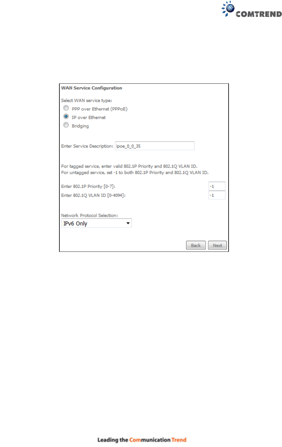
E2.7 IP over ETHERNET (IPoE) – IPv6
STEP 1: Select the IP over Ethernet radio button and click Next. Then select IPv6 only from the
drop-down box at the bottom off the screen and click Next.
For tagged service, enter valid 802.1P Priority and 802.1Q VLAN ID.
For untagged service, set -1 to both 802.1P Priority and 802.1Q VLAN ID.
190
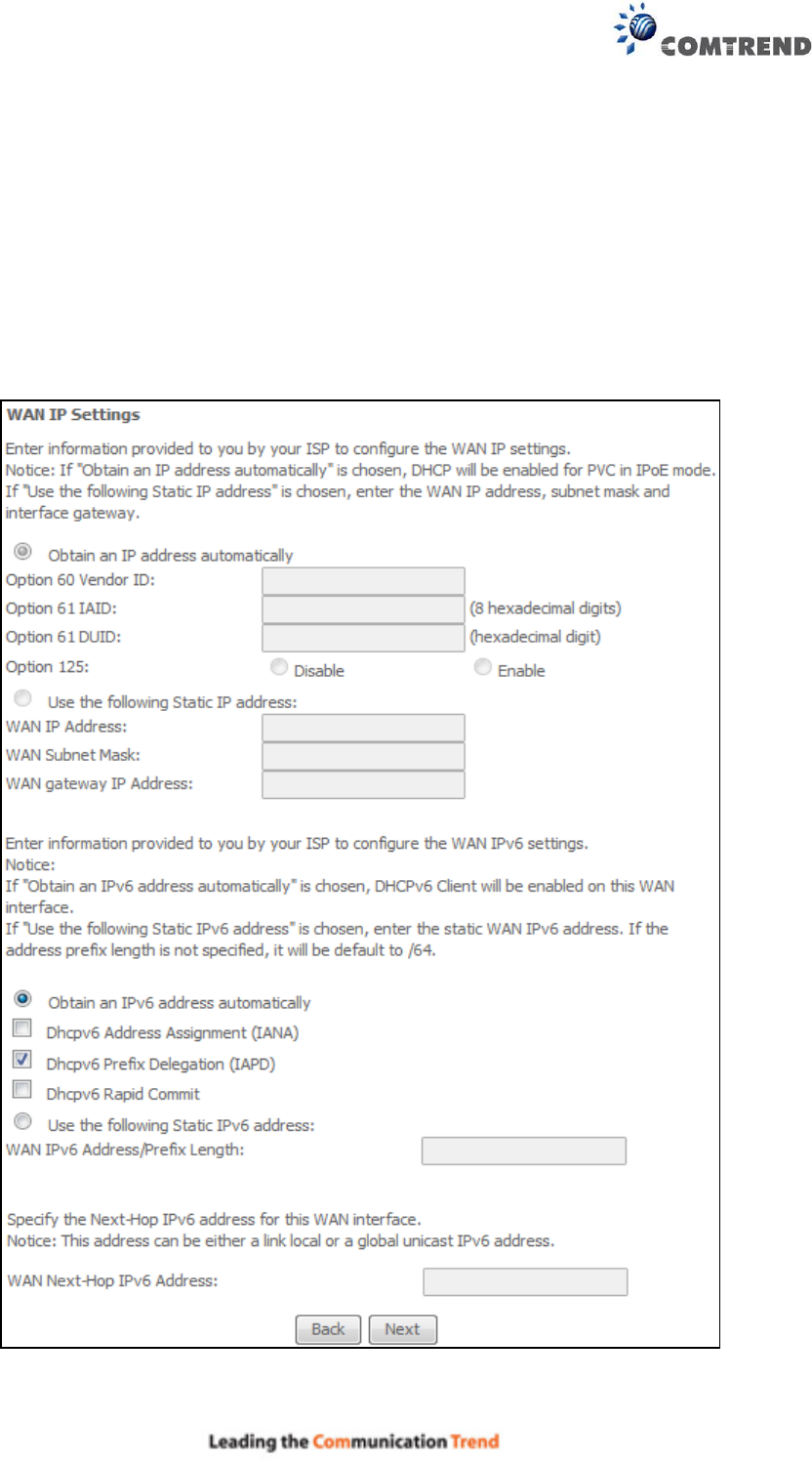
STEP 2: The WAN IP settings screen provides access to the DHCP server settings.
You can select the Obtain an IP address automatically radio button to enable DHCP
(use the DHCP Options only if necessary). However, if you prefer, you can use the
Static IP address method instead to assign WAN IP address, Subnet Mask and
Default Gateway manually.
Enter information provided to you by your ISP to configure the WAN IPv6 settings.
Notice: If “Obtain an IPv6 address automatically” is chosen, DHCP client will be enabled on this
WAN interface.
If “Use the following Static IPv6 address” is chosen, enter the static WAN IPv6 address. If the
address prefix length is not specified, it will be default to /64.
Click Next to continue or click Back to return to the previous step.

191
DHCP6C FOR ADDRESS ASSIGNMENT (IANA)
The Internet Assigned Numbers Authority (IANA) is a department of ICANN responsible for
coordinating some of the key elements that keep the Internet running smoothly. Whilst the
Internet is renowned for being a worldwide network free from central coordination, there is a
technical need for some key parts of the Internet to be globally coordinated, and this coordination
role is undertaken by IANA.
Specifically, IANA allocates and maintains unique codes and numbering systems that are used in
the technical standards (“protocols”) that drive the Internet.
IANA’s various activities can be broadly grouped in to three categories:
• Domain Names
IANA manages the DNS Root, the .int and .arpa domains, and an IDN
practices resource.
• Number Resources
IANA coordinates the global pool of IP and AS numbers, providing them to
Regional Internet Registries.
• Protocol Assignments
Internet protocols’ numbering systems are managed by IANA in conjunction
with standards bodies.
DHCP6C FOR PREFIX DELEGATION (IAPD)
An Identity Association for Prefix Delegation (IAPD) is a collection of prefixes assigned to a
requesting device. A requesting device may have more than one IAPD; for example, one for each
of its interfaces.
A prefix-delegating router (DHCPv6 server) selects prefixes to be assigned to a requesting router
(DHCPv6 client) upon receiving a request from the client. The server can select prefixes for a
requesting client by using static and dynamic assignment mechanisms. Administrators can
manually configure a list of prefixes and associated preferred and valid lifetimes for an IAPD of a
specific client that is identified by its DUID.
When the delegating router receives a request from a client, it checks if there is a static binding
configured for the IAPD in the client’s message. If a static binding is present, the prefixes in the
binding are returned to the client. If no such binding is found, the server attempts to assign
prefixes for the client from other sources.
An IPv6 prefix delegating router can also select prefixes for a requesting router based on an
external authority such as a RADIUS server using the Framed-IPv6-Prefix attribute.
DHCP6C FOR RAPID COMMIT
Rapid-Commit; is the process (option) in which a Requesting Router (DHCP Client) obtains
"configurable information" (configurable parameters) from a Delegating Router (DHCP Server) by
using a rapid DHCPv6 two-message exchange. The messages that are exchanged between the
two routers (RR and DR) are called the DHCPv6 "SOLICIT" message and the DHCPv6 "REPLY"
message.
WAN NEXT-HOP IPv6 ADDRESS
Specify the Next-Hop IPv6 address for this WAN interface.
This address can be either a link local or a global unicast IPv6 address.
192
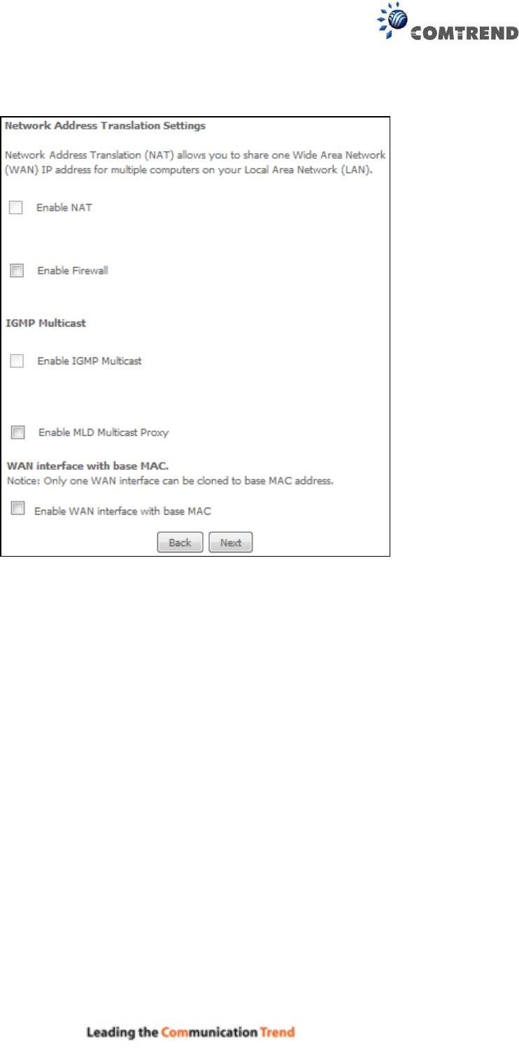
STEP 3: This screen provides access to NAT, Firewall and IGMP Multicast settings. Enable each
by selecting the appropriate checkbox .
Click Next to continue or click Back to return to the previous step.
ENABLE NAT
If the LAN is configured with a private IP address, the user should select this checkbox . The
NAT submenu will appear in the Advanced Setup menu after reboot. On the other hand, if a
private IP address is not used on the LAN side (i.e. the LAN side is using a public IP), this checkbox
should not be selected, so as to free up system resources for improved performance.
ENABLE FIREWALL
If this checkbox is selected, the Security submenu will be displayed on the Advanced Setup
menu after reboot. If firewall is not necessary, this checkbox should not be selected so as to
free up system resources for better performance.
Enable IGMP Multicast
Tick the checkbox to enable Internet Group Membership Protocol (IGMP) multicast. This
protocol is used by IPv6 hosts to report their multicast group memberships to any neighboring
multicast routers.
ENABLE MLD MULTICAST PROXY
Multicast Listener Discovery (MLD) is a component of the Internet Protocol Version 6 (IPv6) suite.
MLD is used by IPv6 routers for discovering multicast listeners on a directly attached link, much
like IGMP is used in IPv4. The protocol is embedded in ICMPv6 instead of using a separate
protocol.
193
WAN interface with base MAC
Enable this option to use the router’s base MAC address as the MAC address for this WAN
interface.
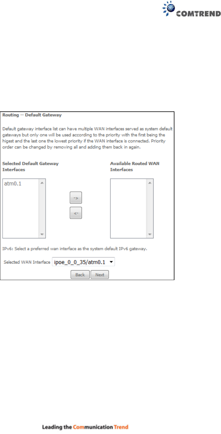
STEP 4: To choose an interface to be the default gateway. Also, select a
preferred WAN interface as the system default IPv6 gateway (from the
drop-down box).
Click Next to continue or click Back to return to the previous step.

194
STEP 5: Select DNS Server Interface from available WAN interfaces OR enter
Static DNS server IP addresses for the system. In ATM mode, if only a
single PVC with IPoA or static IPoE protocol is configured, Static DNS
server IP addresses must be entered.
Select the configured WAN interface for IPv6 DNS server information OR enter the static IPv6 DNS
server Addresses. Note that selecting a WAN interface for IPv6 DNS server will enable DHCPv6
Client on that interface.
Click Next to continue or click Back to return to the previous step.
195
STEP 6: The WAN Setup - Summary screen shows a preview of the WAN service
you have configured. Check these settings and click Apply/Save if
they are correct, or click Back to modify them.
After clicking Apply/Save, the new service should appear on the main screen.
196
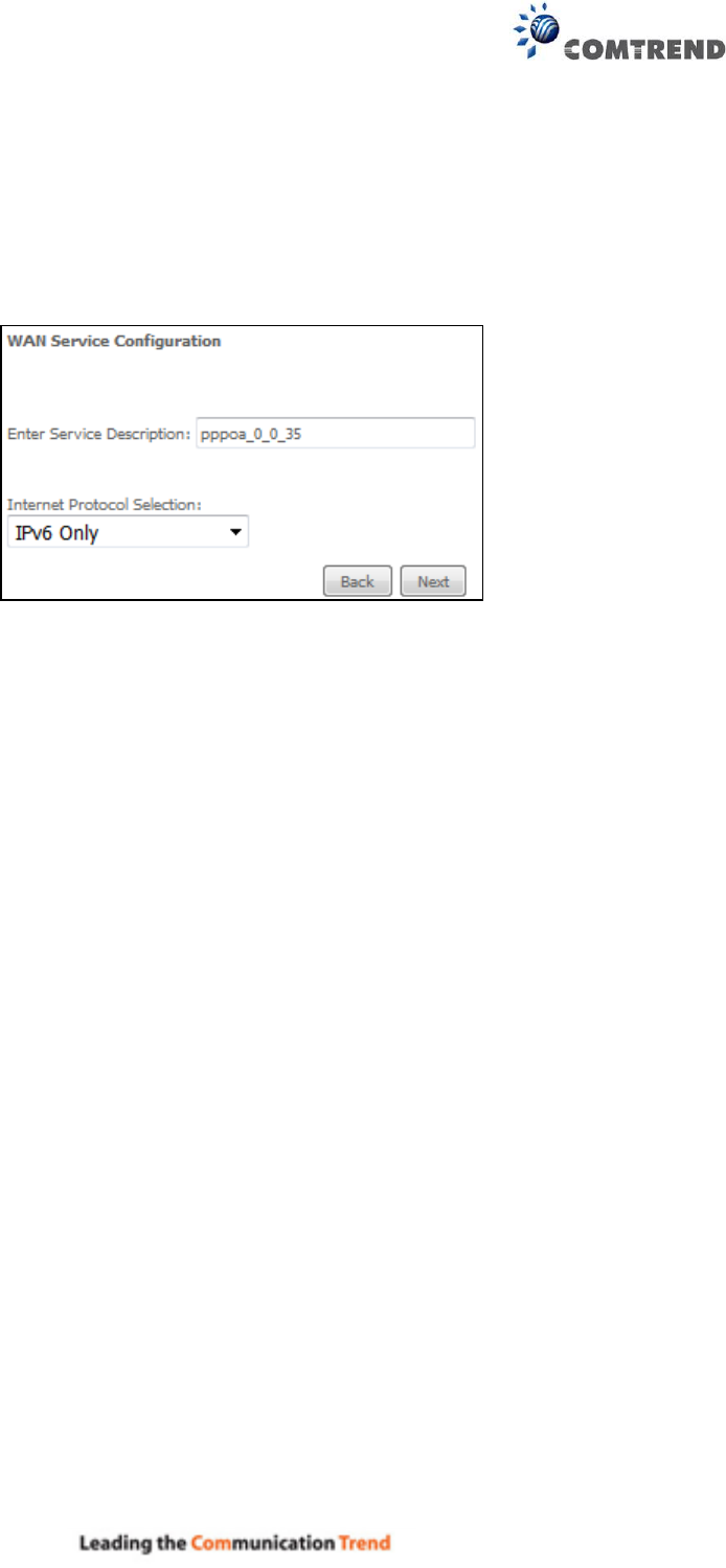
E2.8 PPP over ATM (PPPoA) – IPv6
STEP 1: Select IPv6 Only from the drop-down box at the bottom
of this screen and click Next.
197
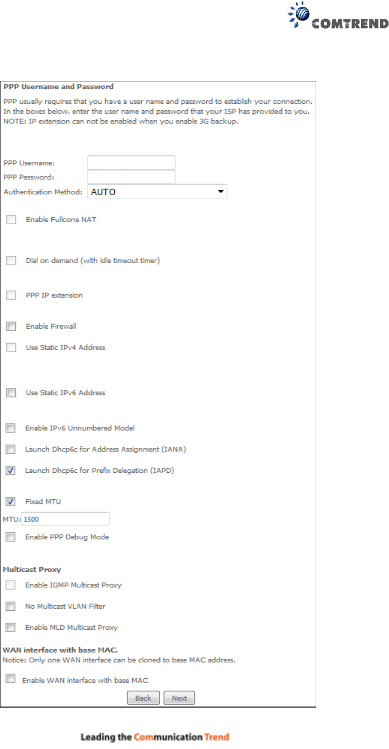
STEP 2: On the next screen, enter the PPP settings as provided by your ISP.
Click Next to continue or click Back to return to the previous step.
198
PPP SETTINGS
The PPP username and password are dependent on the requirements of the ISP. The user name
can be a maximum of 256 characters and the password a maximum of 32 characters in length.
(Authentication Method: AUTO, PAP, CHAP, or MSCHAP.)
ENABLE FULLCONE NAT
This option becomes available when NAT is enabled. Known as one-to-one NAT, all requests from
the same internal IP address and port are mapped to the same external IP address and port. An
external host can send a packet to the internal host, by sending a packet to the mapped external
address.
DIAL ON DEMAND
The AR-5313u can be configured to disconnect if there is no activity for a period of time by
selecting the Dial on demand checkbox . You must also enter an inactivity timeout period in
the range of 1 to 4320 minutes.
PPP IP EXTENSION
The PPP IP Extension is a special feature deployed by some service providers. Unless your
service provider specifically requires this setup, do not select it.
PPP IP Extension does the following:
Allows only one PC on the LAN.
Disables NAT and Firewall.
The device becomes the default gateway and DNS server to the PC through DHCP
using the LAN interface IP address.
The device extends the IP subnet at the remote service provider to the LAN PC. i.e.
the PC becomes a host belonging to the same IP subnet.
The device bridges the IP packets between WAN and LAN ports, unless the packet is
addressed to the device’s LAN IP address.
The public IP address assigned by the remote side using the PPP/IPCP protocol is
actually not used on the WAN PPP interface. Instead, it is forwarded to the PC LAN
interface through DHCP. Only one PC on the LAN can be connected to the remote,
since the DHCP server within the device has only a single IP address to assign to a LAN
device.
ENABLE FIREWALL
If this checkbox is selected, the Security submenu will be displayed on the Advanced Setup
menu after reboot. If firewall is not necessary, this checkbox should not be selected to free up
system resources for better performance.
USE STATIC IPv4 ADDRESS
Unless your service provider specially requires it, do not select this checkbox . If selected,
enter the static IP address in the IP Address field. Also, don’t forget to adjust the IP
configuration to Static IP Mode as described in 3.2 IP Configuration.

199
USE STATIC IPv6 ADDRESS
Unless your service provider specially requires it, do not select this checkbox . If selected,
enter the static IP address in the IPv6 Address field.
Don’t forget to adjust the IP configuration to Static IP Mode as described in section 3.2 IP
Configuration.
ENABLE IPv6 UNNUMBERED MODEL
The IP unnumbered configuration command allows you to enable IP processing on a serial
interface without assigning it an explicit IP address. The IP unnumbered interface can "borrow"
the IP address of another interface already configured on the router, which conserves network
and address space.
LAUNCH DHCP6C FOR ADDRESS ASSIGNMENT (IANA)
The Internet Assigned Numbers Authority (IANA) is a department of ICANN responsible for
coordinating some of the key elements that keep the Internet running smoothly. Whilst the
Internet is renowned for being a worldwide network free from central coordination, there is a
technical need for some key parts of the Internet to be globally coordinated, and this coordination
role is undertaken by IANA.
Specifically, IANA allocates and maintains unique codes and numbering systems that are used in
the technical standards (“protocols”) that drive the Internet.
IANA’s various activities can be broadly grouped in to three categories:
• Domain Names
IANA manages the DNS Root, the .int and .arpa domains, and an IDN
practices resource.
• Number Resources
IANA coordinates the global pool of IP and AS numbers, providing them to
Regional Internet Registries.
• Protocol Assignments
Internet protocols’ numbering systems are managed by IANA in conjunction
with standards bodies.
LAUNCH DHCP6C FOR PREFIX DELEGATION (IAPD)
An Identity Association for Prefix Delegation (IAPD) is a collection of prefixes assigned to a
requesting device. A requesting device may have more than one IAPD; for example, one for each
of its interfaces.
A prefix-delegating router (DHCPv6 server) selects prefixes to be assigned to a requesting router
(DHCPv6 client) upon receiving a request from the client. The server can select prefixes for a
requesting client by using static and dynamic assignment mechanisms. Administrators can
manually configure a list of prefixes and associated preferred and valid lifetimes for an IAPD of a
specific client that is identified by its DUID.
When the delegating router receives a request from a client, it checks if there is a static binding
configured for the IAPD in the client’s message. If a static binding is present, the prefixes in the
binding are returned to the client. If no such binding is found, the server attempts to assign
prefixes for the client from other sources.
An IPv6 prefix delegating router can also select prefixes for a requesting router based on an
external authority such as a RADIUS server using the Framed-IPv6-Prefix attribute.
FIXED MTU
Fixed Maximum Transmission Unit. The size (in bytes) of largest protocol data unit which the layer
can pass onwards. This value is 1500 for PPPoA.
ENABLE PPP DEBUG MODE
When this option is selected, the system will put more PPP connection information into the system
log. This is for debugging errors and not for normal usage.
200
Enable IGMP Multicast Proxy
Tick the checkbox to enable Internet Group Membership Protocol (IGMP) multicast. This
protocol is used by IPv6 hosts to report their multicast group memberships to any neighboring
multicast routers.
No Multicast VLAN Filter
Tick the checkbox to Enable/Disable multicast VLAN filter.
ENABLE MLD MULTICAST PROXY
Multicast Listener Discovery (MLD) is a component of the Internet Protocol Version 6 (IPv6) suite.
MLD is used by IPv6 routers for discovering multicast listeners on a directly attached link, much
like IGMP is used in IPv4. The protocol is embedded in ICMPv6 instead of using a separate
protocol.
WAN interface with base MAC
Enable this option to use the router’s base MAC address as the MAC address for this WAN
interface.
STEP 3: Choose an interface to be the default gateway.
Click Next to continue or click Back to return to the previous step.
201
STEP 4: Select DNS Server Interface from available WAN interfaces OR enter
Static DNS server IP addresses for the system. In ATM mode, if only a
single PVC with IPoA or static IPoE protocol is configured, Static DNS
server IP addresses must be entered.
Select the configured WAN interface for IPv6 DNS server information OR enter the static IPv6 DNS
server Addresses. Note that selecting a WAN interface for IPv6 DNS server will enable DHCPv6
Client on that interface.
Click Next to continue or click Back to return to the previous step.
202
STEP 5: The WAN Setup - Summary screen shows a preview of the WAN service
you have configured. Check these settings and click Apply/Save if they
are correct, or click Back to modify them.
After clicking Apply/Save, the new service should appear on the main screen.
203
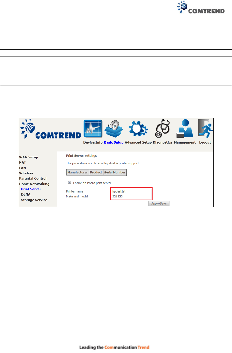
Appendix F – Printer Server
These steps explain the procedure for enabling the Printer Server.
NOTE: This function only applies to models with a USB host port.
STEP 1: Enable Print Server from Web User Interface. Select the Enable on-board print server
checkbox and input Printer name & Make and model. Click the Apply/Save button.
NOTE: The Printer name can be any text string up to 40 characters.
The Make and model can be any text string up to 128 characters.
204
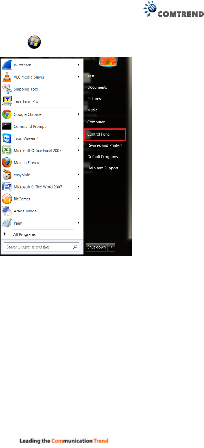
STEP 2: Click the Windows start button. Then select Control Panel.
205
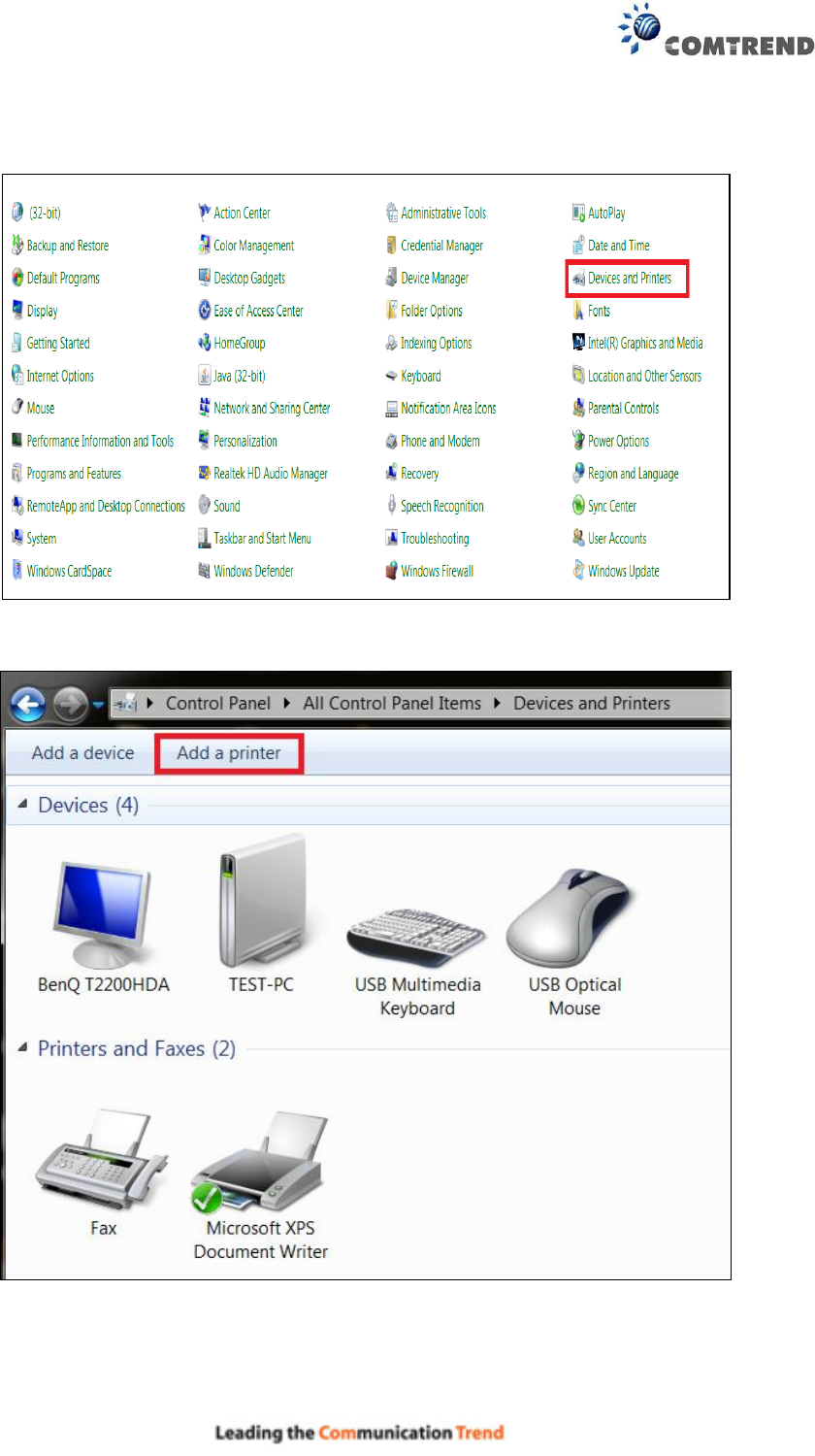
STEP 3: Select Devices and Printers.
STEP 4: Select Add a printer.
206
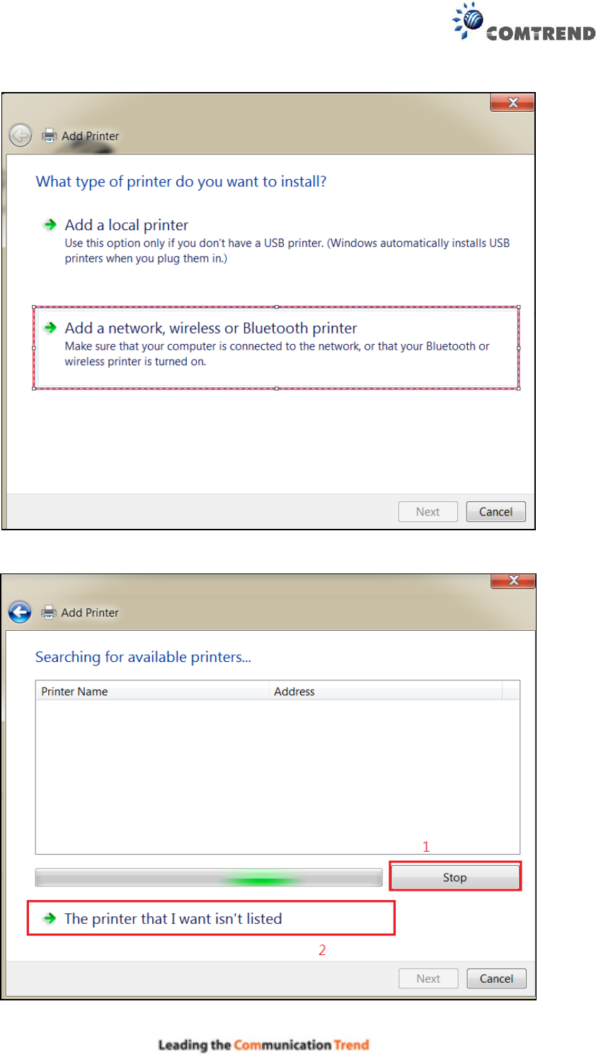
STEP 5: Select Add a network, wireless or Bluetooth printer.
STEP 6: Click the Stop button. Select The printer that I want isn’t listed.
207
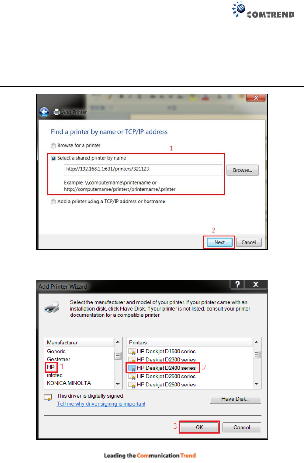
STEP 7: Choose Select a shared printer by name. Then input the printer link
and click Next.
http://LAN IP:631/printers/the name of the printer
NOTE: The printer name must be the same name inputted in the WEB UI “printer server
settings” as in step 1.
STEP 8: Select the manufacturer and model of your printer then, click OK.
208
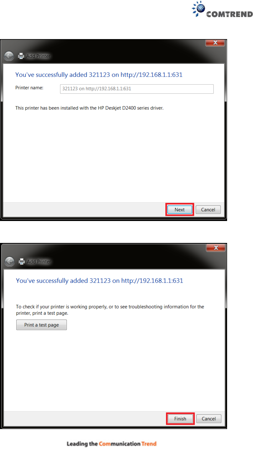
STEP 9: The printer has been successfully installed. Click the Next button.
STEP 10: Click Finish (or print a test page if required).
209
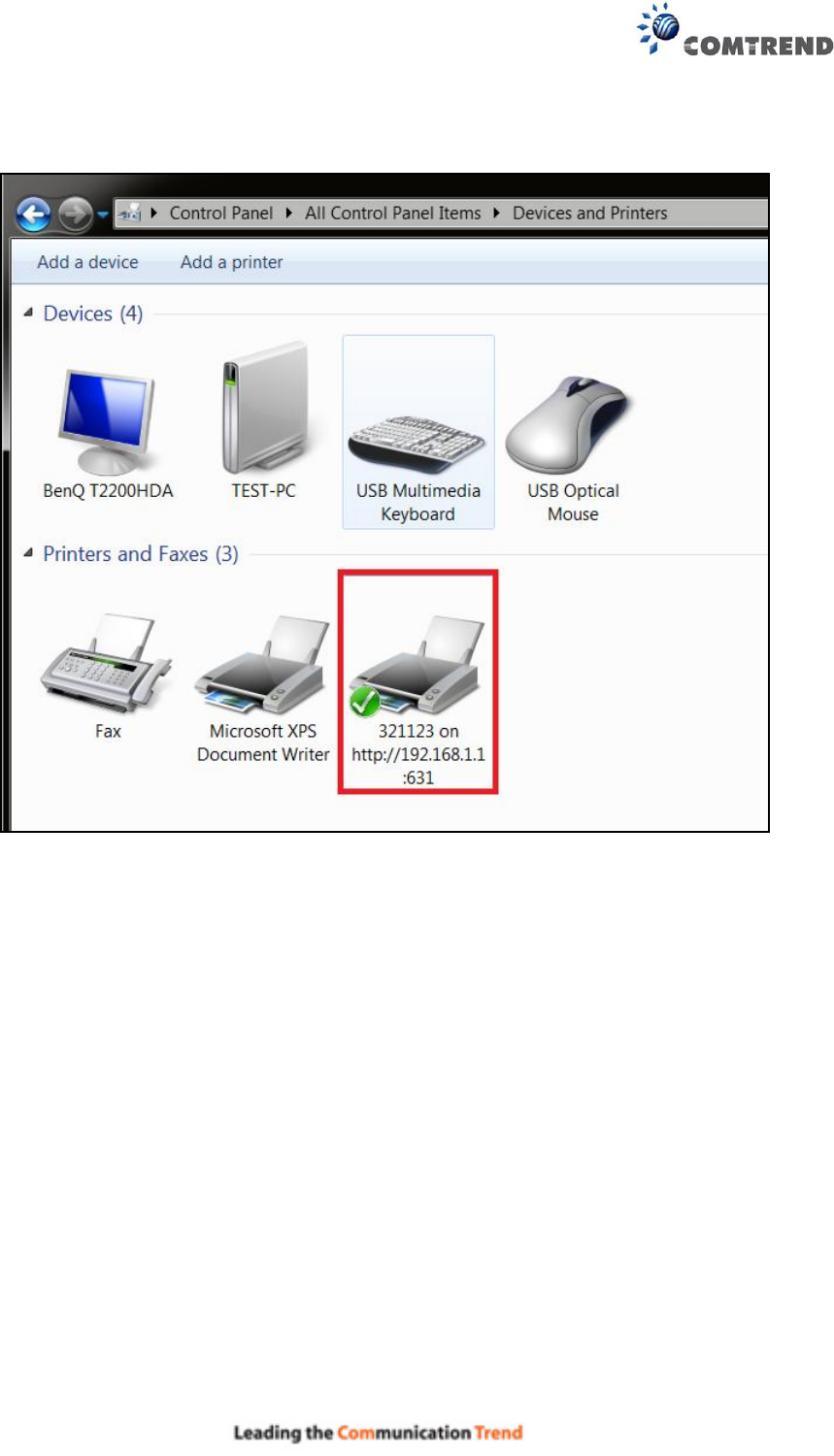
STEP 11: Go to Control Panel All Control Panel Items Devices and Printers to
confirm that the printer has been configured.