Comtrend NL-3111U A/VDSL Bonded Router User Manual UM NexusLink 3111u draft
Comtrend Corporation A/VDSL Bonded Router UM NexusLink 3111u draft
UserManual.wiki
>
Comtrend
>
NL-3111U User Manual
>
5.Users manual-1R1
Contents
1.
5.Users manual-1R1
2.
5.Users manual-2 R1
5.Users manual-1R1
Navigation menu
Upload a User Manual
Namespaces
Wiki Guide
HTML
PDF
Info
Views
User Manual
Discussion / Help
Navigation
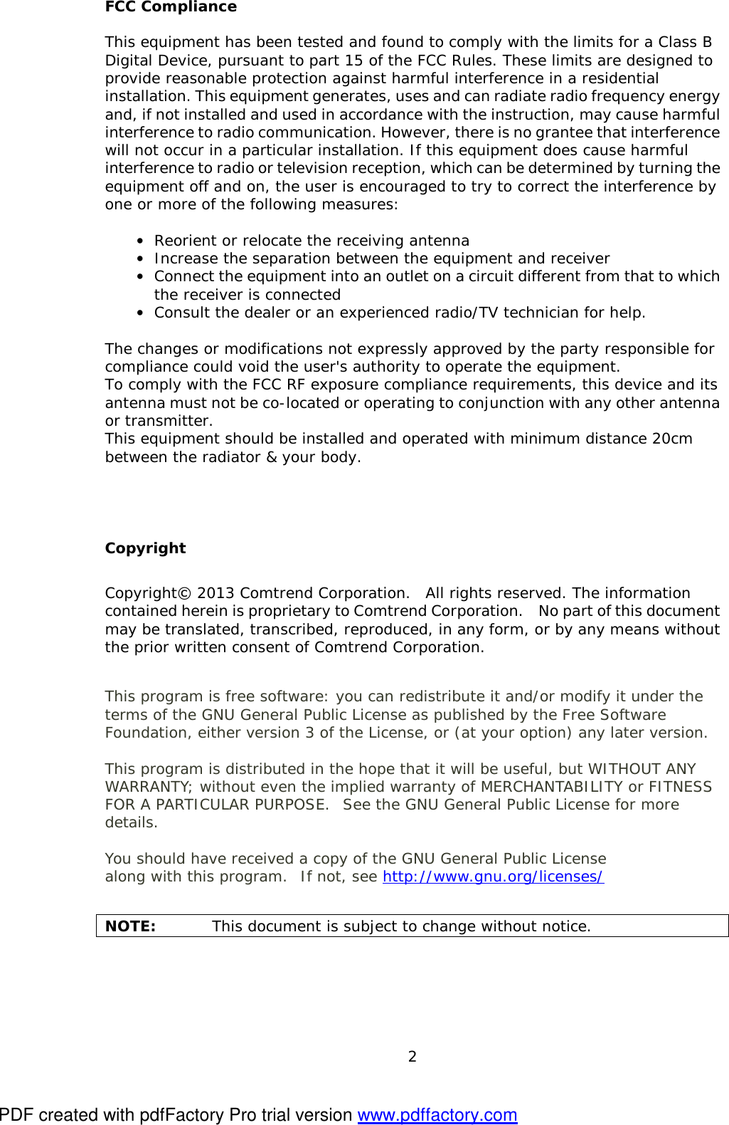
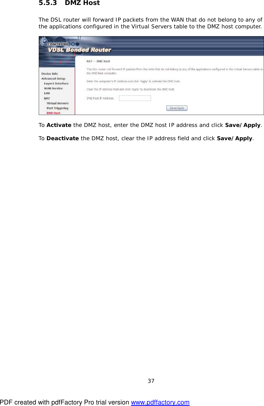
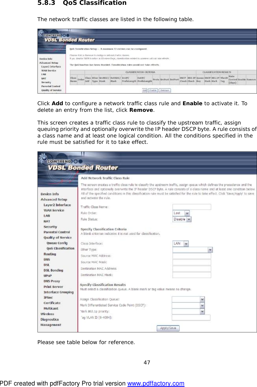
![48 Field Description Traffic Class Name Enter a name for the traffic class. Rule Order Last is the only option. Rule Status Disable or enable the rule. Classification Criteria Class Interface Select an interface (i.e. Local, eth0-4, wl0) Ether Type Set the Ethernet type (e.g. IP, ARP, IPv6). Source MAC Address A packet belongs to SET-1, if a binary-AND of its source MAC address with the Source MAC Mask is equal to the binary-AND of the Source MAC Mask and this field. Source MAC Mask This is the mask used to decide how many bits are checked in Source MAC Address. Destination MAC Address A packet belongs to SET-1 then the result that the Destination MAC Address of its header binary-AND to the Destination MAC Mask must equal to the result that this field binary-AND to the Destination MAC Mask. Destination MAC Mask This is the mask used to decide how many bits are checked in Destination MAC Address. Classification Results Assign Classification Queue The queue configurations are presented in this format: “Interfacename&Prece P&Queue Q” where P and Q are the Precedence and Queue Key values for the corresponding Interface as listed on the Queue Config screen. Mark Differentiated Service Code Point The selected Code Point gives the corresponding priority to packets that satisfy the rule. Mark 802.1p Priority Select between 0-7. Lower values have higher priority. Tag VLAN ID Enter a 802.1Q VLAN ID tag [2-4094] PDF created with pdfFactory Pro trial version www.pdffactory.com](https://usermanual.wiki/Comtrend/NL-3111U.5-Users-manual-1R1/User-Guide-2003202-Page-49.png)
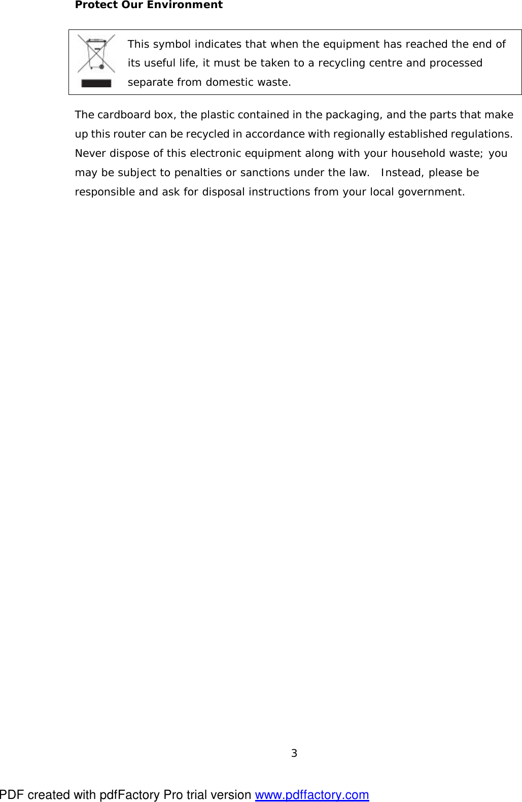
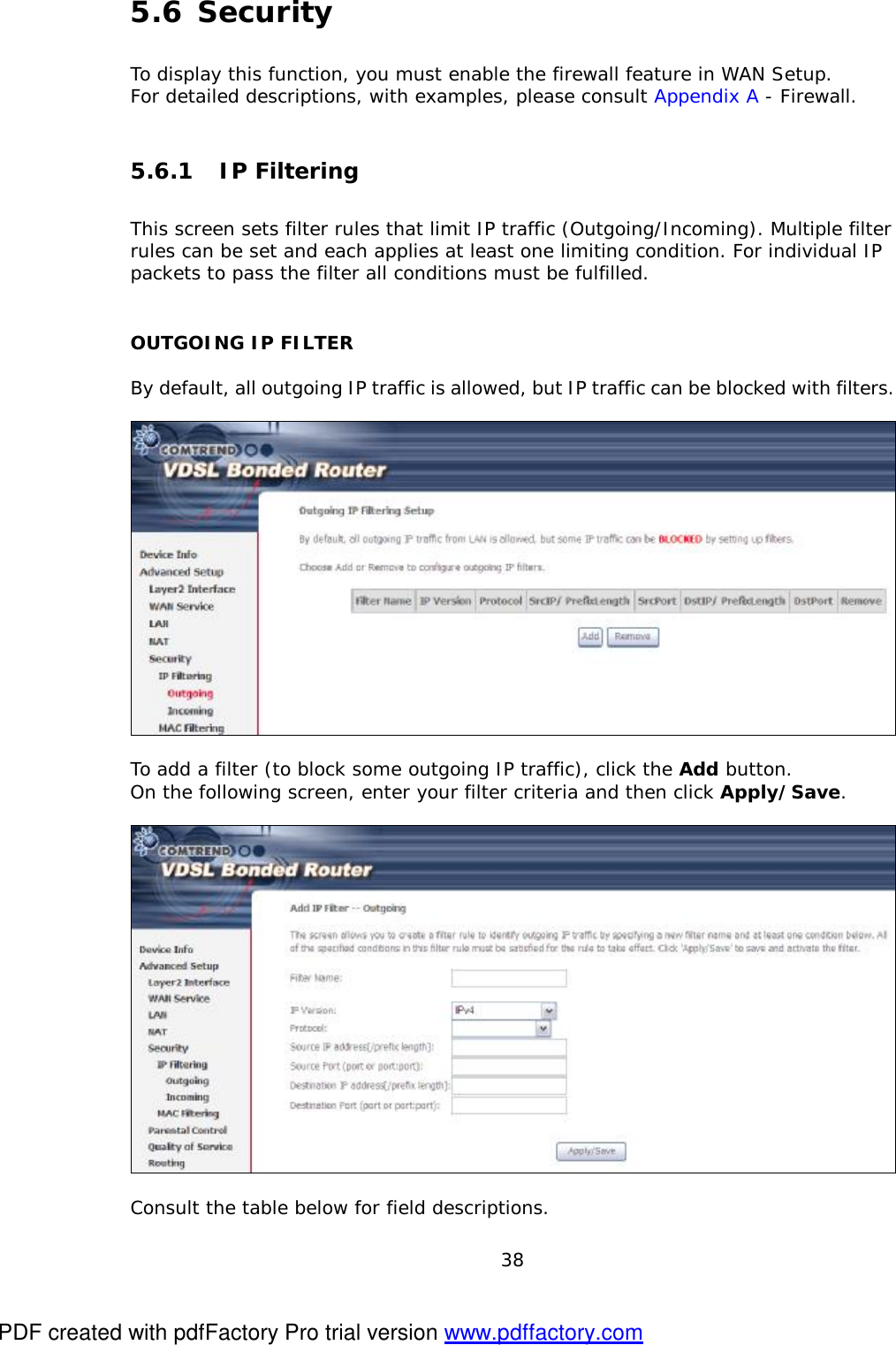
![73 Option Description Disable WMM Advertise Stops the router from ‘advertising’ its Wireless Multimedia (WMM) functionality, which provides basic quality of service for time-sensitive applications (e.g. VoIP, Video). Enable Wireless Multicast Forwarding Select the checkbox þ to enable this function. SSID [1-32 characters] Sets the wireless network name. SSID stands for Service Set Identifier. All stations must be configured with the correct SSID to access the WLAN. If the SSID does not match, that user will not be granted access. BSSID The BSSID is a 48-bit identity used to identify a particular BSS (Basic Service Set) within an area. In Infrastructure BSS networks, the BSSID is the MAC (Media Access Control) address of the AP (Access Point); and in Independent BSS or ad hoc networks, the BSSID is generated randomly. Country A drop-down menu that permits worldwide and specific national settings. Local regulations limit channel range: US= worldwide, Japan=1-14, Jordan= 10-13, Israel= 1-13 Max Clients The maximum number of clients that can access the router. Wireless - Guest / Virtual Access Points This router supports multiple SSIDs called Guest SSIDs or Virtual Access Points. To enable one or more Guest SSIDs select the checkboxes þ in the Enabled column. To hide a Guest SSID, select its checkbox þ in the Hidden column. Do the same for Isolate Clients and Disable WMM Advertise. For a description of these two functions, see the previous entries for “Clients Isolation” and “Disable WMM Advertise”. Similarly, for Enable WMF, Max Clients and BSSID, consult the matching entries in this table. NOTE: Remote wireless hosts cannot scan Guest SSIDs. PDF created with pdfFactory Pro trial version www.pdffactory.com](https://usermanual.wiki/Comtrend/NL-3111U.5-Users-manual-1R1/User-Guide-2003202-Page-74.png)