Comtrend NL-3111U A/VDSL Bonded Router User Manual UM NexusLink 3111u draft
Comtrend Corporation A/VDSL Bonded Router UM NexusLink 3111u draft
Comtrend >
Contents
- 1. 5.Users manual-1R1
- 2. 5.Users manual-2 R1
5.Users manual-1R1

1
Preface
This manual provides information related to the installation and operation of this
device. The individual reading this manual is presumed to have a basic
understanding of telecommunications terminology and concepts.
If you find the product to be inoperable or malfunctioning, please contact technical
support for immediate service by email at INT-support@comtrend.com
For product update, new product release, manual revision, or software upgrades,
please visit our website at http://www.comtrend.com
Important Safety Instructions
With reference to unpacking, installation, use, and maintenance of your electronic
device, the following basic guidelines are recommended:
• Do not use or install this product near water, to avoid fire or shock hazard. For
example, near a bathtub, kitchen sink or laundry tub, or near a swimming pool.
Also, do not expose the equipment to rain or damp areas (e.g. a wet basement).
• Do not connect the power supply cord on elevated surfaces. Allow it to lie freely.
There should be no obstructions in its path and no heavy items should be placed
on the cord. In addition, do not walk on, step on, or mistreat the cord.
• Use only the power cord and adapter that are shipped with this device.
• To safeguard the equipment against overheating, make sure that all openings in
the unit that offer exposure to air are not blocked.
• Avoid using a telephone (other than a cordless type) during an electrical storm.
There may be a remote risk of electric shock from lightening. Also, do not use
the telephone to report a gas leak in the vicinity of the leak.
• Never install telephone wiring during stormy weather conditions.
CAUTION:
n To reduce the risk of fire, use only No. 26 AWG or larger
telecommunication line cord.
n Always disconnect all telephone lines from the wall outlet before servicing
or disassembling this equipment.
WARNING
n Disconnect the power line from the device before servicing.
n Power supply specifications are clearly stated in Appendix C -
Specifications.
PDF created with pdfFactory Pro trial version www.pdffactory.com

2
FCC Compliance
This equipment has been tested and found to comply with the limits for a Class B
Digital Device, pursuant to part 15 of the FCC Rules. These limits are designed to
provide reasonable protection against harmful interference in a residential
installation. This equipment generates, uses and can radiate radio frequency energy
and, if not installed and used in accordance with the instruction, may cause harmful
interference to radio communication. However, there is no grantee that interference
will not occur in a particular installation. If this equipment does cause harmful
interference to radio or television reception, which can be determined by turning the
equipment off and on, the user is encouraged to try to correct the interference by
one or more of the following measures:
• Reorient or relocate the receiving antenna
• Increase the separation between the equipment and receiver
• Connect the equipment into an outlet on a circuit different from that to which
the receiver is connected
• Consult the dealer or an experienced radio/TV technician for help.
The changes or modifications not expressly approved by the party responsible for
compliance could void the user's authority to operate the equipment.
To comply with the FCC RF exposure compliance requirements, this device and its
antenna must not be co-located or operating to conjunction with any other antenna
or transmitter.
This equipment should be installed and operated with minimum distance 20cm
between the radiator & your body.
Copyright
Copyright© 2013 Comtrend Corporation. All rights reserved. The information
contained herein is proprietary to Comtrend Corporation. No part of this document
may be translated, transcribed, reproduced, in any form, or by any means without
the prior written consent of Comtrend Corporation.
This program is free software: you can redistribute it and/or modify it under the
terms of the GNU General Public License as published by the Free Software
Foundation, either version 3 of the License, or (at your option) any later version.
This program is distributed in the hope that it will be useful, but WITHOUT ANY
WARRANTY; without even the implied warranty of MERCHANTABILITY or FITNESS
FOR A PARTICULAR PURPOSE. See the GNU General Public License for more
details.
You should have received a copy of the GNU General Public License
along with this program. If not, see http://www.gnu.org/licenses/
NOTE: This document is subject to change without notice.
PDF created with pdfFactory Pro trial version www.pdffactory.com

3
Protect Our Environment
This symbol indicates that when the equipment has reached the end of
its useful life, it must be taken to a recycling centre and processed
separate from domestic waste.
The cardboard box, the plastic contained in the packaging, and the parts that make
up this router can be recycled in accordance with regionally established regulations.
Never dispose of this electronic equipment along with your household waste; you
may be subject to penalties or sanctions under the law. Instead, please be
responsible and ask for disposal instructions from your local government.
PDF created with pdfFactory Pro trial version www.pdffactory.com

4
Table of Contents
CHAPTER 1 INTRODUCTION...........................................................................................................6
1.1 FEATURES ........................................................................................................................................6
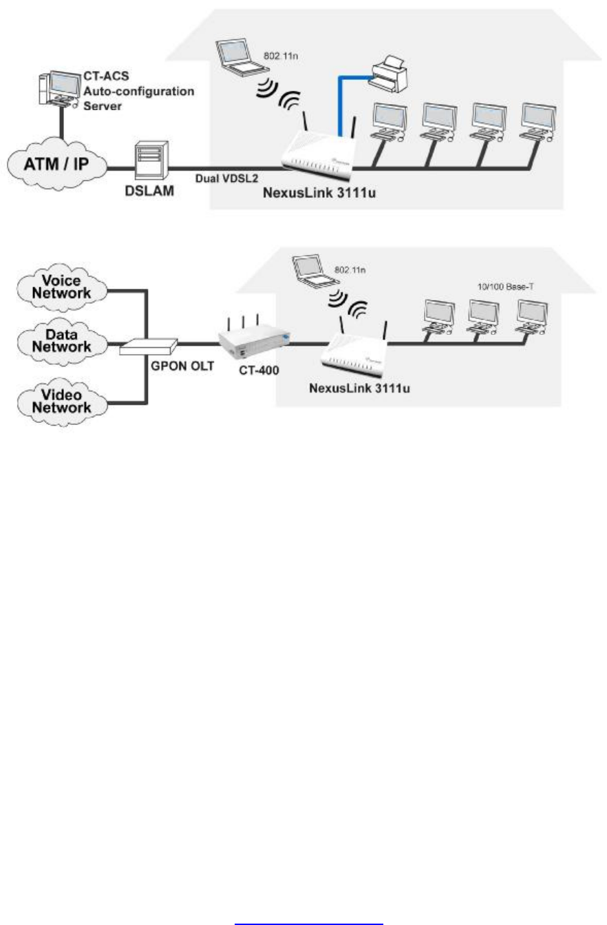
1.2 APPLICATION ...................................................................................................................................7
CHAPTER 2 INSTALLATION.............................................................................................................8
2.1 HARDWARE SETUP...........................................................................................................................8
2.2 LED INDICATORS...........................................................................................................................10
CHAPTER 3 WEB USER INTERFACE............................................................................................12
3.1 DEFAULT SETTINGS........................................................................................................................12
3.2 IP CONFIGURATION........................................................................................................................12
3.3 LOGIN PROCEDURE........................................................................................................................15
CHAPTER 4 DEVICE INFORMATION...........................................................................................17
4.1 WAN.............................................................................................................................................18
4.2 STATISTICS.....................................................................................................................................19
4.2.1 LAN Statistics..................................................................................................................19
4.2.2 WAN Statistics.................................................................................................................20
4.2.3 ATM Statistics.................................................................................................................21
4.2.4 xDSL Statistics................................................................................................................22
4.3 ROUTE ...........................................................................................................................................25
4.4 ARP...............................................................................................................................................26
4.5 DHCP............................................................................................................................................27
CHAPTER 5 ADVANCED SETUP.....................................................................................................28
5.1 LAYER 2 INTERFACE ......................................................................................................................28
5.1.1 ATM Interface.................................................................................................................28
5.1.2 PTM Interface.................................................................................................................29
5.1.3 ETH INTERFACE...........................................................................................................29
5.2 WAN SERVICE ...............................................................................................................................30
5.3 LAN..............................................................................................................................................31
5.4 IPV6 LAN AUTO CONFIGURATION ................................................................................................33
5.5 NAT...............................................................................................................................................34
5.5.1 Virtual Servers................................................................................................................34
5.5.2 Port Triggering...............................................................................................................35
5.5.3 DMZ Host.......................................................................................................................37
5.6 SECURITY ......................................................................................................................................38
5.6.1 IP Filtering.....................................................................................................................38
5.6.2 MAC Filtering.................................................................................................................41
5.7 PARENTAL CONTROL......................................................................................................................42
5.7.1 Time Restriction..............................................................................................................42
5.7.2 URL Filter.......................................................................................................................43
5.8 QUALITY OF SERVICE (QOS)..........................................................................................................45
5.8.1 Queue Management Configuration.................................................................................45
5.8.2 Queue Configuration......................................................................................................46
5.8.3 QoS Classification..........................................................................................................47
5.9 ROUTING .......................................................................................................................................49
5.9.1 Default Gateway.............................................................................................................49
5.9.2 Static Route.....................................................................................................................50
5.9.3 Policy Routing................................................................................................................51
5.9.4 RIP..................................................................................................................................52
5.10 DNS............................................................................................................................................53
5.10.1 DNS Server.....................................................................................................................53
5.10.2 Dynamic DNS.................................................................................................................54
5.11 DSL.............................................................................................................................................56
5.12 DSL BONDING.............................................................................................................................58
5.13 UPNP...........................................................................................................................................59
5.14 DNS PROXY ................................................................................................................................60
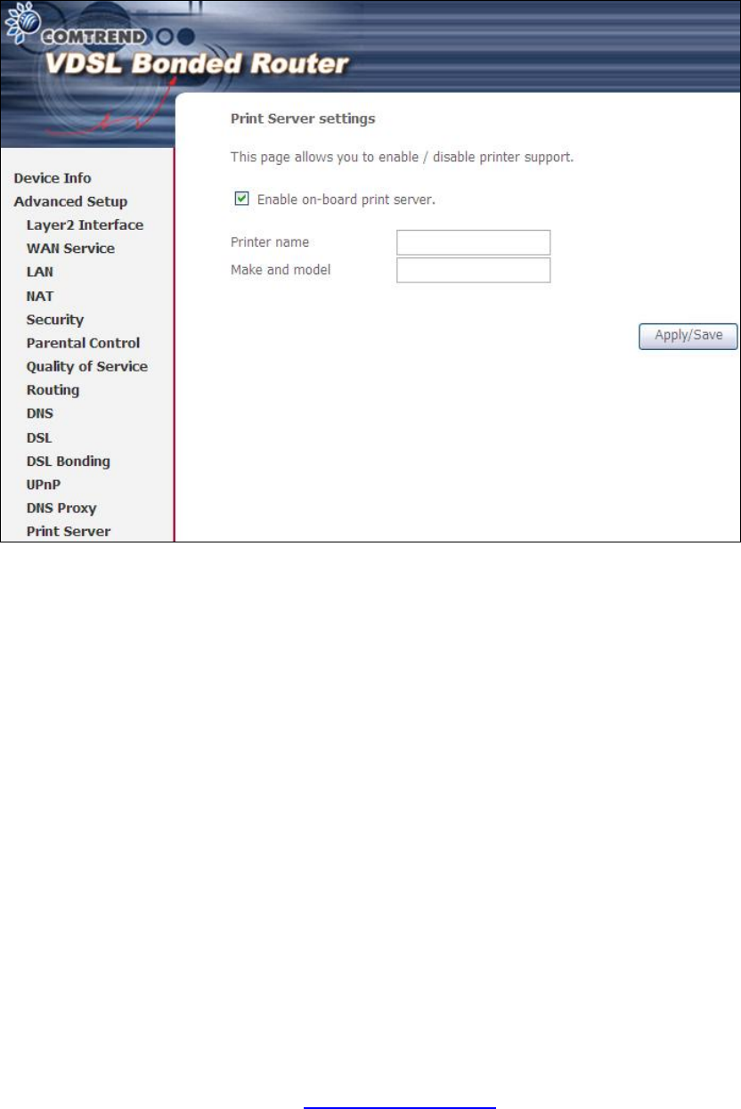
5.15 PRINT SERVER..............................................................................................................................61
PDF created with pdfFactory Pro trial version www.pdffactory.com

5
5.16 INTERFACE GROUPING.................................................................................................................62
5.17 IP SEC..........................................................................................................................................64
5.18 CERTIFICATE ................................................................................................................................67
5.18.1 Local...............................................................................................................................67
5.18.2 Trusted CA......................................................................................................................70
5.19 MULTICAST..................................................................................................................................71
CHAPTER 6 WIRELESS....................................................................................................................72
6.1 BASIC ............................................................................................................................................72
6.2 SECURITY ......................................................................................................................................74
6.2.1 WPS.......................................................................................................................................76
6.3 MAC FILTER..................................................................................................................................81
6.4 WIRELESS BRIDGE .........................................................................................................................82
6.5 ADVANCED ....................................................................................................................................83
6.6 STATION INFO ................................................................................................................................86
CHAPTER 7 DIAGNOSTICS.............................................................................................................87
CHAPTER 8 MANAGEMENT...........................................................................................................88
8.1 SETTINGS.......................................................................................................................................88
8.1.1 Backup Settings...............................................................................................................88
8.1.2 Update Settings...............................................................................................................88
8.1.3 Restore Default...............................................................................................................89
8.2 SYSTEM LOG .................................................................................................................................90
8.3 SNMP AGENT................................................................................................................................92
8.4 TR-069 CLIENT .............................................................................................................................93
8.5 INTERNET TIME..............................................................................................................................94
8.6 ACCESS CONTROL..........................................................................................................................95
8.6.1 Passwords.......................................................................................................................95
8.7 UPDATE SOFTWARE........................................................................................................................95
8.8 REBOOT.........................................................................................................................................96
APPENDIX A - FIREWALL................................................................................................................97
APPENDIX B - PIN ASSIGNMENTS..............................................................................................100
APPENDIX C - SPECIFICATIONS.................................................................................................101
APPENDIX D - SSH CLIENT...........................................................................................................104
APPENDIX E - WSC EXTERNAL REGISTRAR..........................................................................105
APPENDIX F - PRINTER SERVER................................................................................................108
APPENDIX G - CONNECTION SETUP.........................................................................................114
PDF created with pdfFactory Pro trial version www.pdffactory.com

6
Chapter 1 Introduction
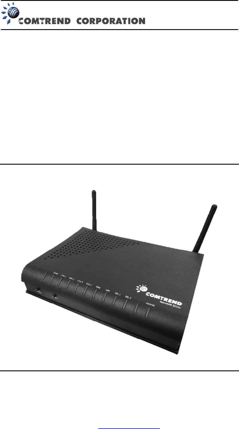
The NEXUSLINK 3111u MULTI-DSL Bonded Router features flexible networking
connectivity with dual DSL line capability, four 10/100 Ethernet ports, one Gigabit
Ethernet port and one USB Host port. It has robust routing capabilities to segment
and direct data streams and allows for multiple data encapsulations.
An integrated 802.11n (draft) WLAN Access Point (AP) provides faster wireless
connections with increased range, when compared with 802.11b and 802.11g,
without sacrificing backwards compatibility with these older wireless standards.
WPS (Wi-Fi Protected Setup) and Wi-Fi On/Off buttons are positioned on the front
panel for easy wireless network setup and control.
1.1 Features
• Integrated 802.11n AP
(802.11b/g backward-compatible) • Firmware upgrade and configuration
• MULTI-DSL 12a/12b profile support • Auto PVC configuration
• IP and Per-VC packet level QoS • Supports up to 8 VCs
• WPA/WPA2 and 802.1x • WMM & UPnP
• RADIUS client • IP/MAC filtering
• Static routing & RIP/RIP v2 • Dynamic IP assignment
• NAT/PAT • Parental Control
• IGMP Proxy and fast leave • DHCP Server/Client
• Web-based management • DNS Relay/Proxy
• Supports remote administration • FTP/TFTP server
• Configuration backup and restoration
• TR-069/TR-098/TR-104/TR-111
PDF created with pdfFactory Pro trial version www.pdffactory.com
8
Chapter 2 Installation
2.1 Hardware Setup
Follow the instructions below to complete the hardware setup.
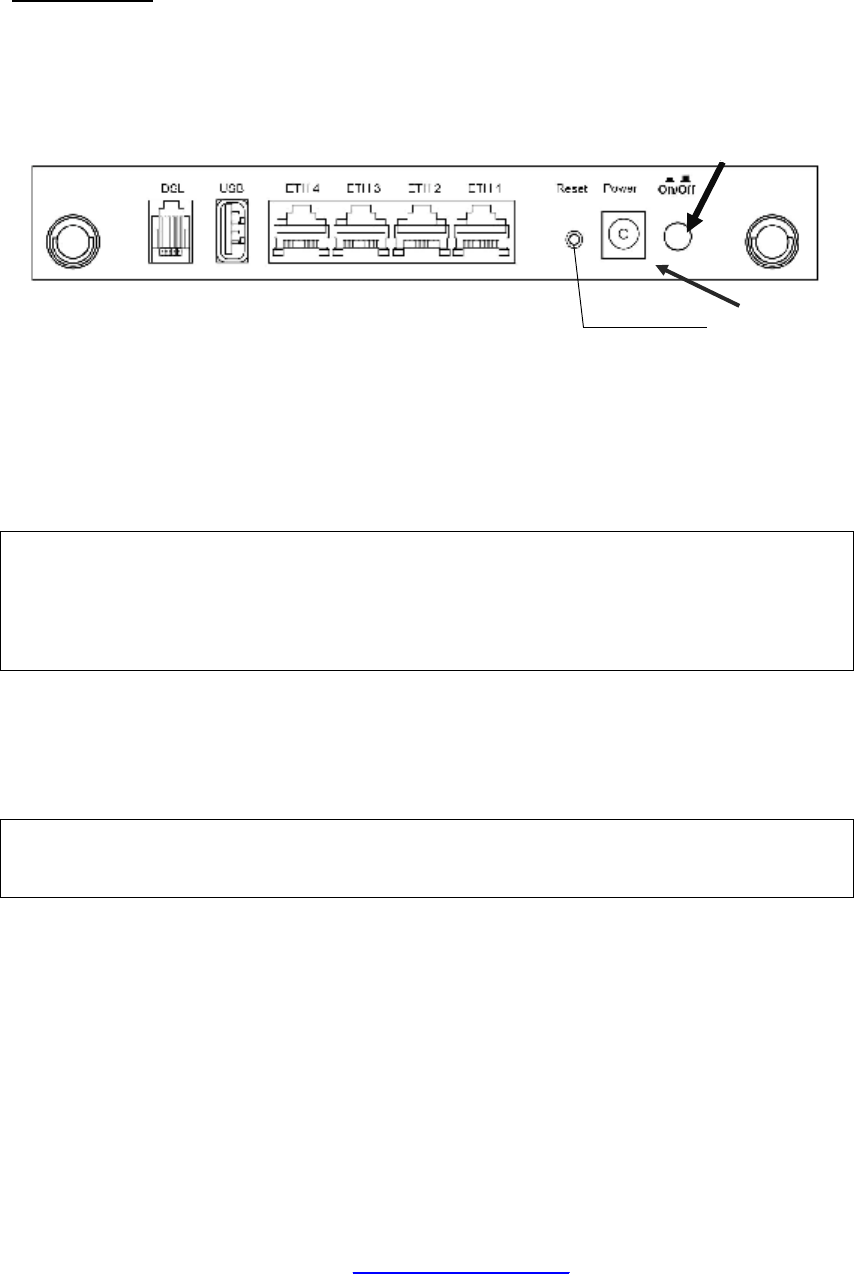
BACK PANEL
The figure below shows the back panel of the device.
1.2
Power ON
Press the power button to the OFF position (OUT). Connect the power adapter to the
power port. Attach the power adapter to a wall outlet or other AC source. Press the
power button to the ON position (IN). If the Power LED displays as expected then
the device is ready for setup (see section 2.2 LED Indicators).
Caution 1: If the device fails to power up, or it malfunctions, first verify that the
power cords are connected securely and then power it on again. If the
problem persists, contact technical support.
Caution 2: Before servicing or disassembling this equipment, disconnect all power
cords and telephone lines from their outlets.
Reset Button
Restore the default parameters of the device by pressing the Reset button for 5 to
10 seconds. After the device has rebooted successfully, the front panel should
display as expected (see section 2.2 LED Indicators for details).
NOTE: If pressed down for more than 20 seconds, the NEXUSLINK 3111u will go
into a firmware update state (CFE boot mode). The firmware can then
be updated using an Internet browser pointed to the default IP address.
Ethernet (LAN) Ports
Use 10/100 BASE-T RJ-45 cables to connect up to four network devices. These ports
are auto-sensing MDI/X; so either straight-through or crossover cable can be used.
Gb ETH Port
Use RJ45 straight through or crossover MDI/X cable to connect to Ethernet WAN.
DSL Port
Reset Button
Power Port
Ethernet (LAN) Ports
Ethernet (LAN) Ports
DSL Port
Power Button
PDF created with pdfFactory Pro trial version www.pdffactory.com

9
Connect to an VDSL with this RJ11 Port. This device contains a micro filter which
removes the analog phone signal. If you wish, you can connect a regular telephone
to the same line by using a POTS splitter.
FRONT PANEL
The Wi-Fi & WPS buttons are located on the bottom-left of the front panel, as shown.
WiFi Switch
Press this button to enable/disable the wireless LAN (WLAN).
WPS Button
Press this button to begin searching for WPS clients. These clients must also enable
WPS push button mode (see 6.2.1 WPS for instructions).
PDF created with pdfFactory Pro trial version www.pdffactory.com

10
2.2 LED Indicators
The front panel LED indicators are shown below and explained in the following table.
This information can be used to check the status of the device and its connections.
LED Color
Mode
Description
On Power on
Green
Off Power off
POWER
Red On
POST (Power On Self Test) failure (not bootable) or
Device malfunction1
On IP connected and no traffic detected2
Off Modem power off or modem in bridged mode
Green
Blink IP connected and IP Traffic is passing th
ru the
device (either direction)
INTERNET
Red On
Device attempted to become IP connected and
failed (no DHCP response, no PPPoE response,
PPPoE authentication failed, no IP address from
IPCP, etc.)
On The DSL1 link is established.
Off The DSL1 link is not established.
DSL1 Green
Blink
DSL1 attempting sync:
l
Flashing at 2 Hz with a 50% duty cycle when
trying to detect carrier signal
l
Flashing at 4 Hz with a 50% duty cycle when
the carrier has been detected and the modem
is trying to train
On The DSL2 link is established.
DSL2 Green
Off The DSL2 link is not established.
1 A malfunction is any error of internal sequence or state that will prevent the device from
connecting to the DSLAM or passing customer data. This may be identified at various times
such after power on or during operation through the use of self testing or in operations which
result in a unit state that is not expected or should not occur.
2 IP connected (the device has a WAN IP address from IPCP or DHCP and DSL is up or a
static IP address is configured, PPP negotiation has successfully complete – if used – and DSL
is up ) and no traffic detected. If the IP or PPPoE session is dropped for any other reason, the
light is turned off. The light will turn red when it attempts to reconnect and DHCP or PPPoE
fails
PDF created with pdfFactory Pro trial version www.pdffactory.com

11
Blink
DSL2 attempting sync:
l
Flashing at 2 Hz with a 50% duty cycle when
trying to detect carrier signal
l
Flashing at 4 Hz with a 50% duty cycle when
the carrier has been detected and the
modem
is trying to train
On The wireless module is ready.
Off The wireless module is not installed.
Wireless
Green
Blink Data transmitting or receiving over WLAN.
On WPS enabled and PC connected to WLAN
Off
l WPS disenabled when WPS configured
l After clients connected to router about 5
minutes, LED is off
WPS Green
Blink The router is searching for WPS clients or WPS
un-configured.
On Powered device connected to the associated port
Off No activity, modem power off, no cable or no
powered device connected to the associated port
Yellow
(for
10/100)
Blink Traffic is passing
On Powered device connected to the associated port
Off No activity, modem power off, no cable or no
powered device connected to the associated port
ETH 1
Green
(for
1000) Blink Traffic is passing
On
Powered device connected to the associated port
(includes devices with wake-on-LAN capability
where a slight voltage is supplied to an Ethernet
connection)
Off No activity, modem power off, no cable or no
powered device connected to the associated port
ETH 2~4
Green
Blink LAN activity present (traffic in either direction)
PDF created with pdfFactory Pro trial version www.pdffactory.com

12
Chapter 3 Web User Interface
This section describes how to access the device via the web user interface (WUI)
using an Internet browser such as Internet Explorer (version 5.0 and later).
3.1 Default Settings
The factory default settings of this device are summarized below.
• LAN IP address: 192.168.1.1
• LAN subnet mask: 255.255.255.0
• Administrative access (username: root , password: 12345)
• User access (username: user, password: user)
• Remote (WAN) access (username: support, password: support)
• WLAN access: enabled
Technical Note
During power on, the device initializes all settings to default values. It will then
read the configuration profile from the permanent storage section of flash memory.
The default attributes are overwritten when identical attributes with different values
are configured. The configuration profile in permanent storage can be created via
the web user interface or telnet user interface, or other management protocols.
The factory default configuration can be restored either by pushing the reset button
for more than five seconds until the power indicates LED blinking or by clicking the
Restore Default Configuration option in the Restore Settings screen.
3.2 IP Configuration
DHCP MODE
When the NEXUSLINK 3111u powers up, the onboard DHCP server will switch on.
Basically, the DHCP server issues and reserves IP addresses for LAN devices, such
as your PC.
To obtain an IP address from the DCHP server, follow the steps provided below.
NOTE: The following procedure assumes you are running Windows XP.
However, the general steps involved are similar for most operating
systems (OS). Check your OS support documentation for further details.
STEP 1: From the Network Connections window, open Local Area Connection (You
may also access this screen by double-clicking the Local Area Connection
icon on your taskbar). Click the Properties button.
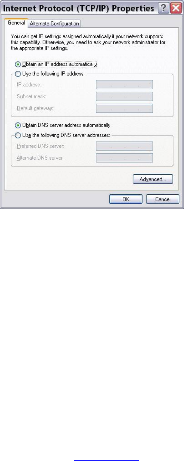
STEP 2: Select Internet Protocol (TCP/IP) and click the Properties button.
STEP 3: Select Obtain an IP address automatically as shown below.
PDF created with pdfFactory Pro trial version www.pdffactory.com
14
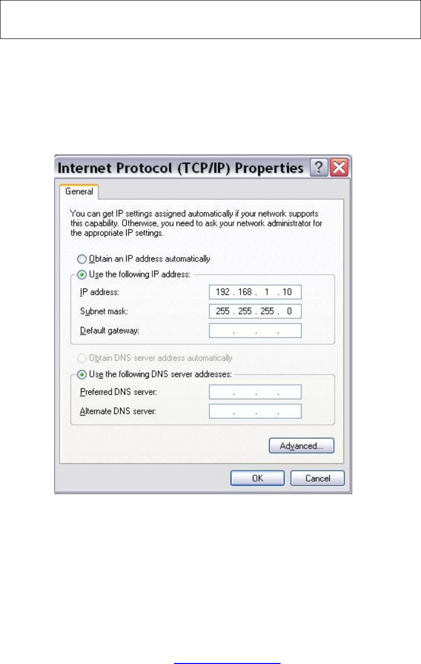
STATIC IP MODE
In static IP mode, you assign IP settings to your PC manually.
Follow these steps to configure your PC IP address to use subnet 192.168.1.10.
NOTE: The following procedure assumes you are running Windows XP.
However, the general steps involved are similar for most operating
systems (OS). Check your OS support documentation for further details.
STEP 1: From the Network Connections window, open Local Area Connection (You
may also access this screen by double-clicking the Local Area Connection
icon on your taskbar). Click the Properties button.
STEP 2: Select Internet Protocol (TCP/IP) and click the Properties button.
STEP 3: Change the IP address to the 192.168.1.10 subnet with subnet mask of
255.255.255.0. The screen should now display as shown below.
STEP 4: Click OK to submit these settings.
PDF created with pdfFactory Pro trial version www.pdffactory.com
15
3.3 Login Procedure
Perform the following steps to login to the web user interface.
NOTE: The default settings can be found in 3.1 Default Settings.
STEP 1: Start the Internet browser and enter the default IP address for the device
in the Web address field. For example, if the default IP address is
192.168.1.1, type http://192.168.1.1.
NOTE: For local administration (i.e. LAN access), the PC running the browser
must be attached to the Ethernet, and not necessarily to the device.
For remote access (i.e. WAN), use the IP address shown on the Chapter 4
Device Information screen and login with remote username and
password.
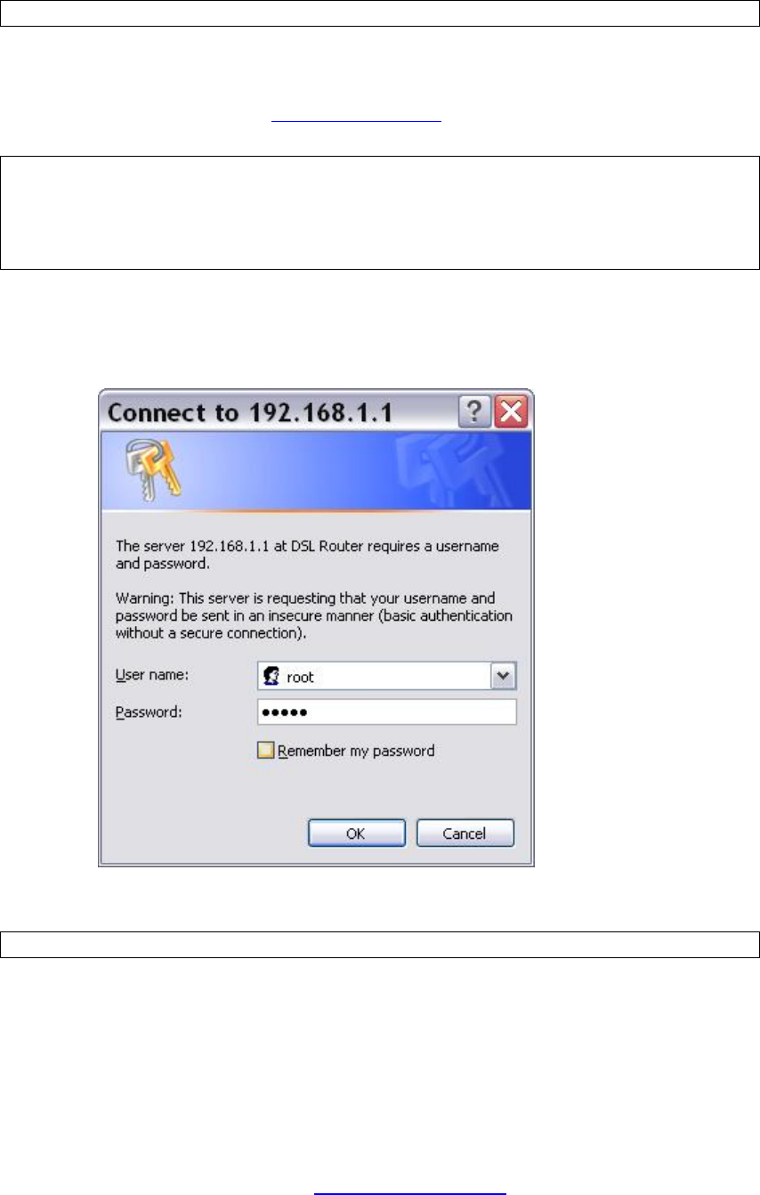
STEP 2: A dialog box will appear, such as the one below. Enter the default
username and password, as defined in section 3.1 Default Settings.
Click OK to continue.
NOTE: The login password can be changed later (see 8.6.1 Passwords).
PDF created with pdfFactory Pro trial version www.pdffactory.com
17
Chapter 4 Device Information
The web user interface window is divided into two frames, the main menu (at left)
and the display screen (on the right). The main menu has several options and
selecting each of these options opens a submenu with more selections.
NOTE: The menu items shown are based upon the configured connection(s) and
user account privileges.
Device Info is the first selection on the main menu so it will be discussed first.
Subsequent chapters will introduce the other main menu options in sequence.
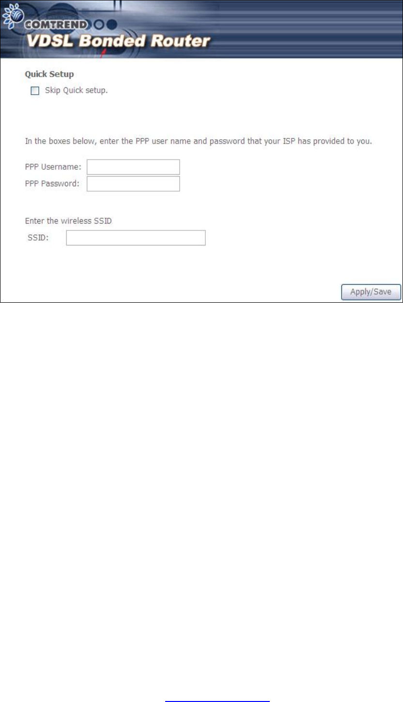
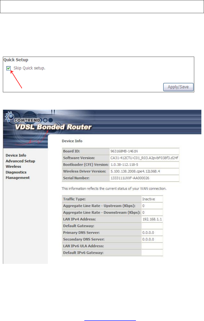
To display the Device Info Summary screen, tick the Skip Quick setup box and click
Apply/Save.
This screen shows hardware, software, IP settings and other related information.
PDF created with pdfFactory Pro trial version www.pdffactory.com
18
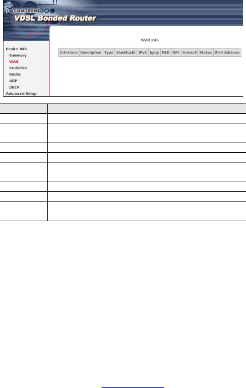
4.1 WAN
Select WAN from the Device Info submenu to display the configured PVC(s).
Heading Description
Interface Name of the interface for WAN
Description Name of the WAN connection
Type Shows the connection type
VlanMuxId Shows 802.1Q VLAN ID
IPv6 Shows WAN IPv6 address
IGMP Shows Internet Group Management Protocol (IGMP) status
MLD Shows Multicast Listener Discovery (MLD) status
NAT Shows Network Address Translation (NAT) status
Firewall Shows the status of Firewall
Status Lists the status of DSL link
IPv4 Address Shows WAN IPv4 address
PDF created with pdfFactory Pro trial version www.pdffactory.com
19
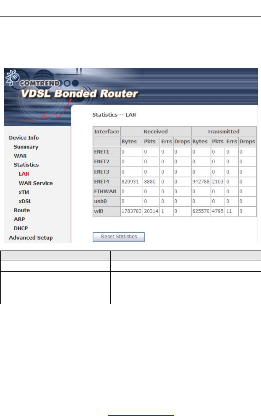
4.2 Statistics
This selection provides LAN, WAN, ATM/PTM and xDSL statistics.
NOTE: These screens are updated automatically every 15 seconds.
Click Reset Statistics to perform a manual update.
4.2.1 LAN Statistics
This screen shows data traffic statistics for each LAN interface.
Heading Description
Interface LAN interface(s)
Received/Transmitted: - Bytes
- Pkts
- Errs
- Drops
Number of Bytes
Number of Packets
Number of packets with errors
Number of dropped packets
PDF created with pdfFactory Pro trial version www.pdffactory.com
20
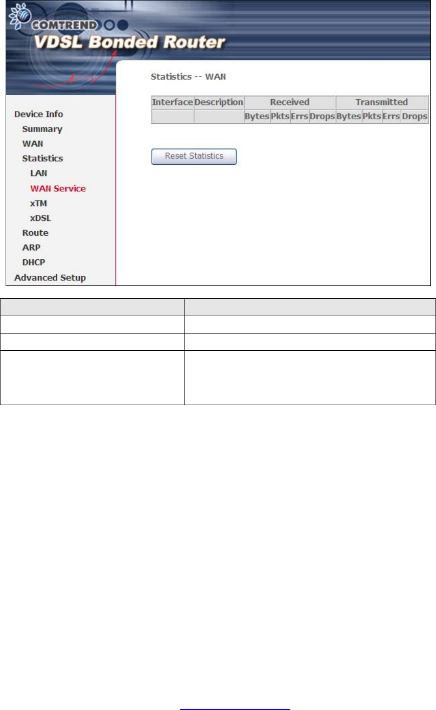
4.2.2 WAN Statistics
This screen shows data traffic statistics for each WAN interface.
Heading Description
Interface WAN interfaces
Description WAN service label
Received/Transmitted - Bytes
- Pkts
- Errs
- Drops
Number of Bytes
Number of Packets
Number of packets with errors
Number of dropped packets
PDF created with pdfFactory Pro trial version www.pdffactory.com

21
4.2.3 ATM Statistics
The following figure shows Asynchronous Transfer Mode (ATM) statistics.
XTM Interface Statistics
Heading Description
Port Number ATM PORT (0-3)
In Octets Number of received octets over the interface
Out Octets Number of transmitted octets over the interface
In Packets Number of packets received over the interface
Out Packets Number of packets transmitted over the interface
In OAM Cells Number of OAM Cells received over the interface
Out OAM Cells Number of OAM Cells transmitted over the interface.
In ASM Cells Number of ASM Cells received over the interface
Out ASM Cells Number of ASM Cells transmitted over the interface
In Packet
Errors Number of packets in Error
In Cell Errors Number of cells in Error
PDF created with pdfFactory Pro trial version www.pdffactory.com
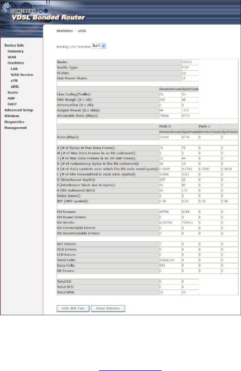

23
Field Description
Mode VDSL, MULTI-DSL
Traffic Type ATM, PTM
Status Lists the status of the DSL link
Link Power State Link output power state.
Line Coding (Trellis) Trellis On/Off
SNR Margin (0.1 dB) Signal to Noise Ratio (SNR) margin
Attenuation (0.1 dB) Estimate of average loop attenuation in the downstream
direction.
Output Power
(0.1 dBm) Total upstream output power
Attainable Rate (Kbps)
The sync rate you would obtain.
Rate (Kbps) Current sync rates downstream/upstream
In VDSL mode, the following section is inserted.
B Number of bytes in Mux Data Frame
M Number of Mux Data Frames in a RS codeword
T Number of Mux Data Frames in an OH sub-frame
R Number of redundancy bytes in the RS codeword
S Number of data symbols the RS codeword spans
L Number of bits transmitted in each data symbol
D The interleaver depth
I The interleaver block size in bytes
N RS codeword size
Delay The delay in milliseconds (msec)
INP DMT symbol
OH Frames Total number of OH frames
OH Frame Errors Number of OH frames received with errors
RS Words Total number of Reed-Solomon code errors
RS Correctable Errors Total Number of RS with correctable errors
RS Uncorrectable
Errors Total Number of RS words with uncorrectable errors
HEC Errors Total Number of Header Error Checksum errors
OCD Errors Total Number of Out-of-Cell Delineation errors
LCD Errors Total number of Loss of Cell Delineation
Total Cells Total number of ATM cells (including idle + data cells)
Data Cells Total number of ATM data cells
Bit Errors Total number of bit errors
PDF created with pdfFactory Pro trial version www.pdffactory.com
24
Total ES Total Number of Errored Seconds
Total SES Total Number of Severely Errored Seconds
Total UAS Total Number of Unavailable Seconds
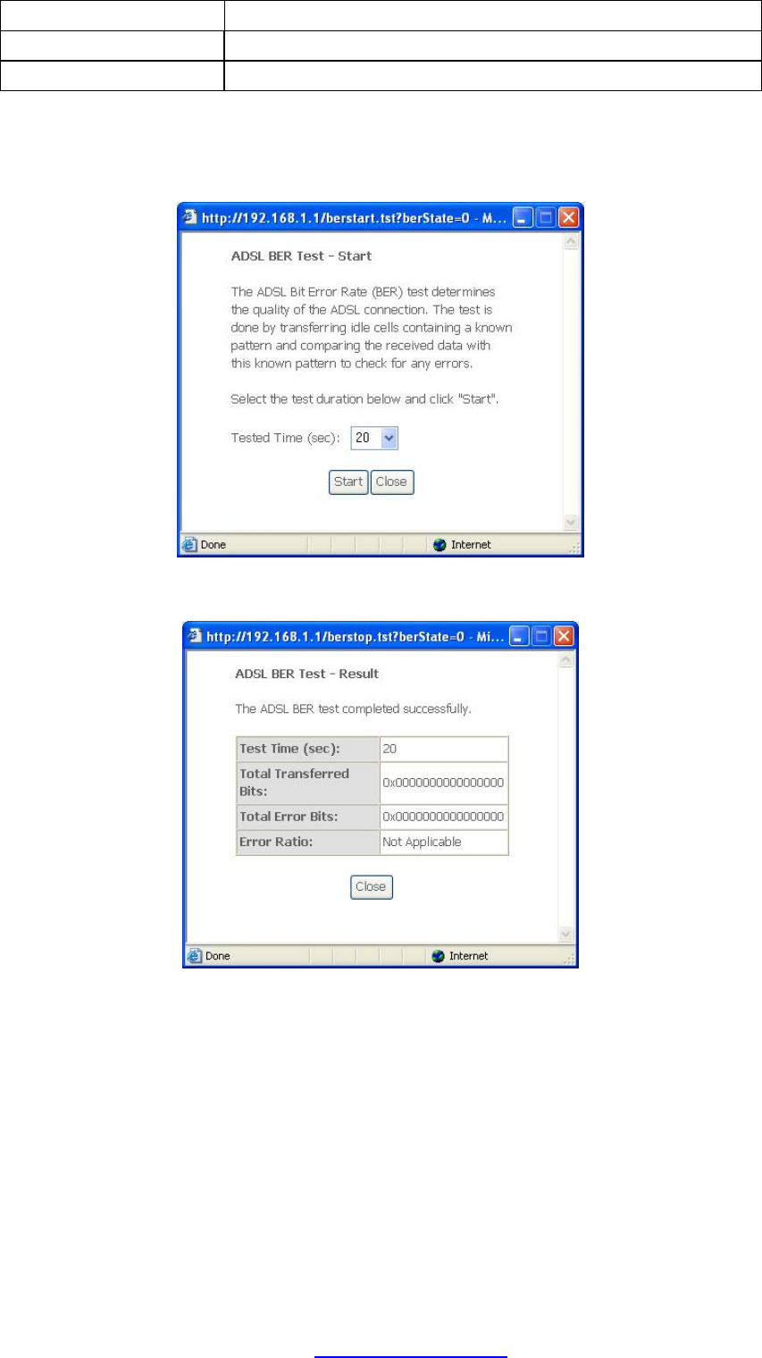
xDSL BER TEST
Click xDSL BER Test on the xDSL Statistics screen to test the Bit Error Rate (BER).
A small pop-up window will open after the button is pressed, as shown below.
Click Start to start the test or click Close to cancel the test. After the BER testing is
complete, the pop-up window will display as follows.
PDF created with pdfFactory Pro trial version www.pdffactory.com
25
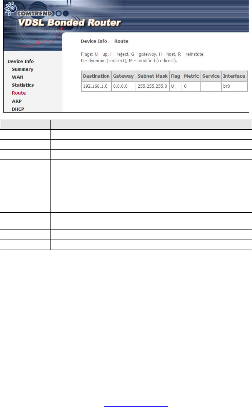
4.3 Route
Choose Route to display the routes that the NEXUSLINK 3111u has found.
Field Description
Destination Destination network or destination host
Gateway Next hub IP address
Subnet Mask Subnet Mask of Destination
Flag U: route is up
!: reject route
G: use gateway
H: target is a host
R: reinstate route for dynamic routing
D: dynamically installed by daemon or redirect
M: modified from routing daemon or redirect
Metric The 'distance' to the target (usually counted in hops). It is not
used by recent kernels, but may be needed by routing daemons.
Service Shows the WAN connection label
Interface Shows connection interfaces
PDF created with pdfFactory Pro trial version www.pdffactory.com
26
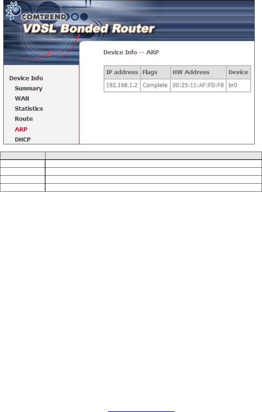
4.4 ARP
Click ARP to display the ARP information.
Field Description
IP address Shows IP address of host pc
Flags Complete, Incomplete, Permanent, or Publish
HW Address
Shows the MAC address of host pc
Device Shows the connection interface
PDF created with pdfFactory Pro trial version www.pdffactory.com
27
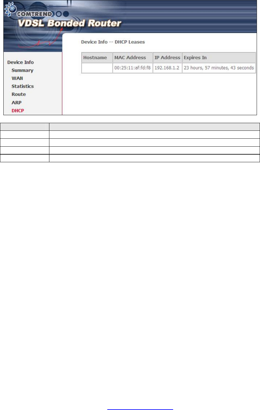
4.5 DHCP
Click DHCP to display all DHCP Leases.
Field Description
Hostname Shows the device/host/PC network name
MAC Address Shows the Ethernet MAC address of the device/host/PC
IP Address Shows IP address of device/host/PC
Expires In Shows how much time is left for each DHCP Lease
PDF created with pdfFactory Pro trial version www.pdffactory.com
28
Chapter 5 Advanced Setup
5.1 Layer 2 Interface
The ATM, PTM and ETH WAN interface screens are described here.
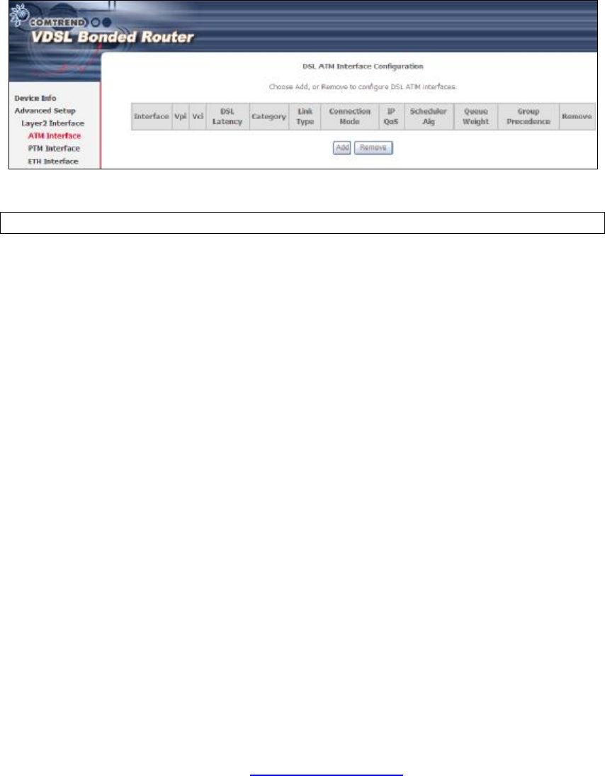
5.1.1 ATM Interface
Add or remove ATM interface connections here.
Click Add to create a new ATM interface (see Appendix G).
NOTE: Up to 8 ATM interfaces can be created and saved in flash memory.
To remove a connection, select its Remove column radio button and click Remove.
PDF created with pdfFactory Pro trial version www.pdffactory.com
29
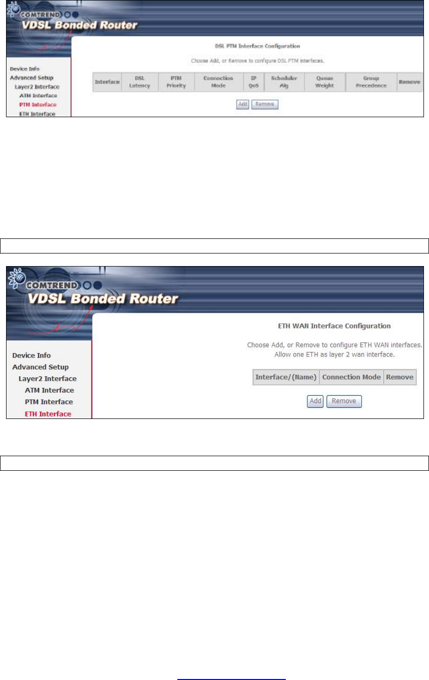
5.1.2 PTM Interface
Add or remove PTM interface connections here.
Click Add to create a new connection (see Appendix G - Connection Setup). To
remove a connection, select its Remove column radio button and click Remove.
5.1.3 ETH INTERFACE
This screen displays the Ethernet WAN Interface configuration.
NOTE: This option only applies to models with an Ethernet WAN port.
Click Add to create a new connection (see Appendix G - Connection Setup).
NOTE: One Ethernet WAN interface can be created and saved in flash memory.
To remove a connection, select its Remove column radio button and click remove.
PDF created with pdfFactory Pro trial version www.pdffactory.com

30
5.2 WAN Service
This screen allows for the configuration of WAN interfaces.
Click the Add button to create a new connection. For connections on ATM or ETH
WAN interfaces see Appendix G - Connection Setup.
NOTE: ETH and ATM service connections cannot coexist. In Default Mode, up to
8 WAN connections can be configured; while VLAN Mux and MSC
Connection Modes support up to 8 WAN connections.
To remove a connection, select its Remove column radio button and click Remove.
Heading Description
Interface Name of the interface for WAN
Description Name of the WAN connection
Type Shows the connection type
Vlan8021p VLAN ID is used for VLAN Tagging (IEEE 802.1Q)
VlanMuxId Shows 802.1Q VLAN ID
ConnId Connection ID
IGMP Shows Internet Group Management Protocol (IGMP) status
NAT Shows Network Address Translation (NAT) status
Firewall Shows the Security status
IPv6 Shows the WAN IPv6 address
MLD Shows Multicast Listener Discovery (MLD) status
Remove Select interfaces to remove
To remove a connection, select its Remove column radio button and click Remove.
To Add a new WAN connection, click the Add button and follow the instructions.
NOTE: Up to 8 PVC profiles can be configured and saved in flash memory. Also,
ETH and PTM/ATM service connections cannot coexist.
PDF created with pdfFactory Pro trial version www.pdffactory.com
31
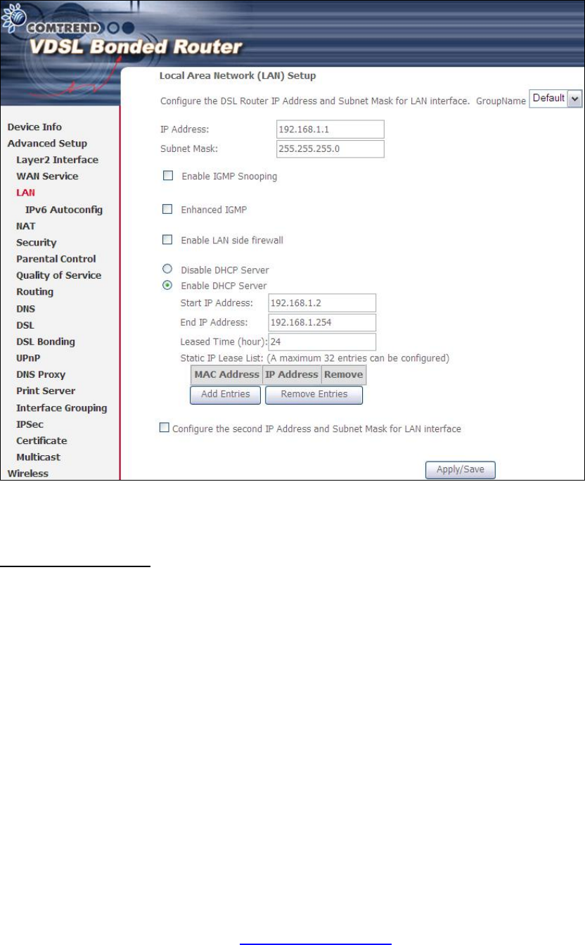
5.3 LAN
Configure the LAN interface settings and then click Apply/Save.
Consult the field descriptions below for more details.
GroupName: Select an Interface Group.
1st LAN INTERFACE
IP Address: Enter the IP address for the LAN port.
Subnet Mask: Enter the subnet mask for the LAN port.
Enable IGMP Snooping: Enable by ticking the checkbox þ.
Standard Mode: In standard mode, multicast traffic will flood to all
bridge ports when no client subscribes to a multicast
group – even if IGMP snooping is enabled.
Blocking Mode: In blocking mode, the multicast data traffic will be
blocked and not flood to all bridge ports when there are
no client subscriptions to any multicast group.
Enhanced IGMP: When enabled, IGMP packets will not flood to all bridge ports.
PDF created with pdfFactory Pro trial version www.pdffactory.com
32
Enable LAN side firewall: Enable by ticking the checkbox þ.
DHCP Server: To enable DHCP, select Enable DHCP server and enter Start and
End IP addresses and the Leased Time. This setting configures the
router to automatically assign IP, default gateway and DNS server
addresses to every PC on your LAN.
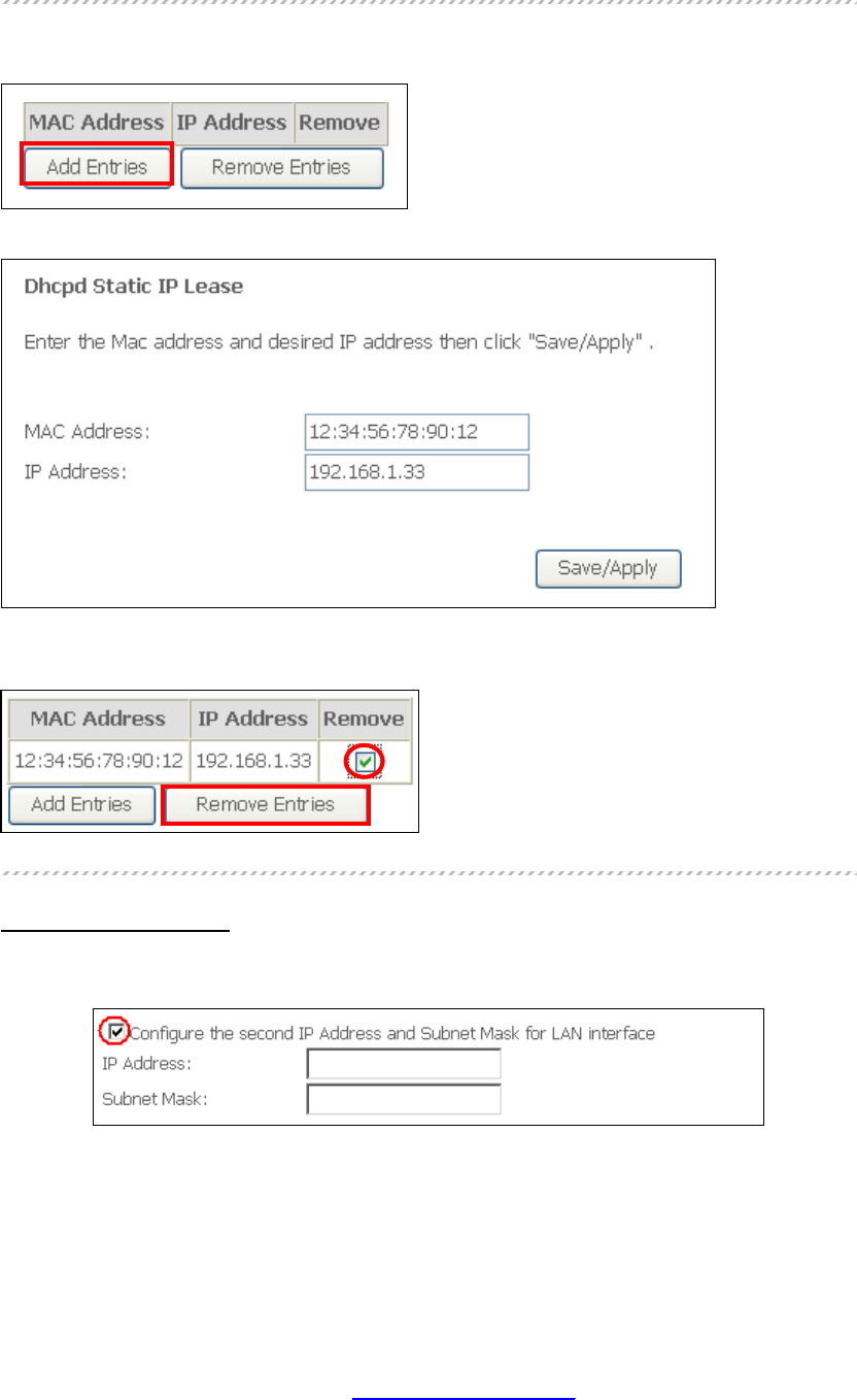
Static IP Lease List: A maximum of 32 entries can be configured.
To add an entry, enter MAC address and Static IP and then click Save/Apply.
To remove an entry, tick the corresponding checkbox þ in the Remove column and
then click the Remove Entries button, as shown below.
2ND LAN INTERFACE
To configure a secondary IP address, tick the checkbox þ outlined (in RED) below.
IP Address: Enter the secondary IP address for the LAN port.
Subnet Mask: Enter the secondary subnet mask for the LAN port.
PDF created with pdfFactory Pro trial version www.pdffactory.com
33
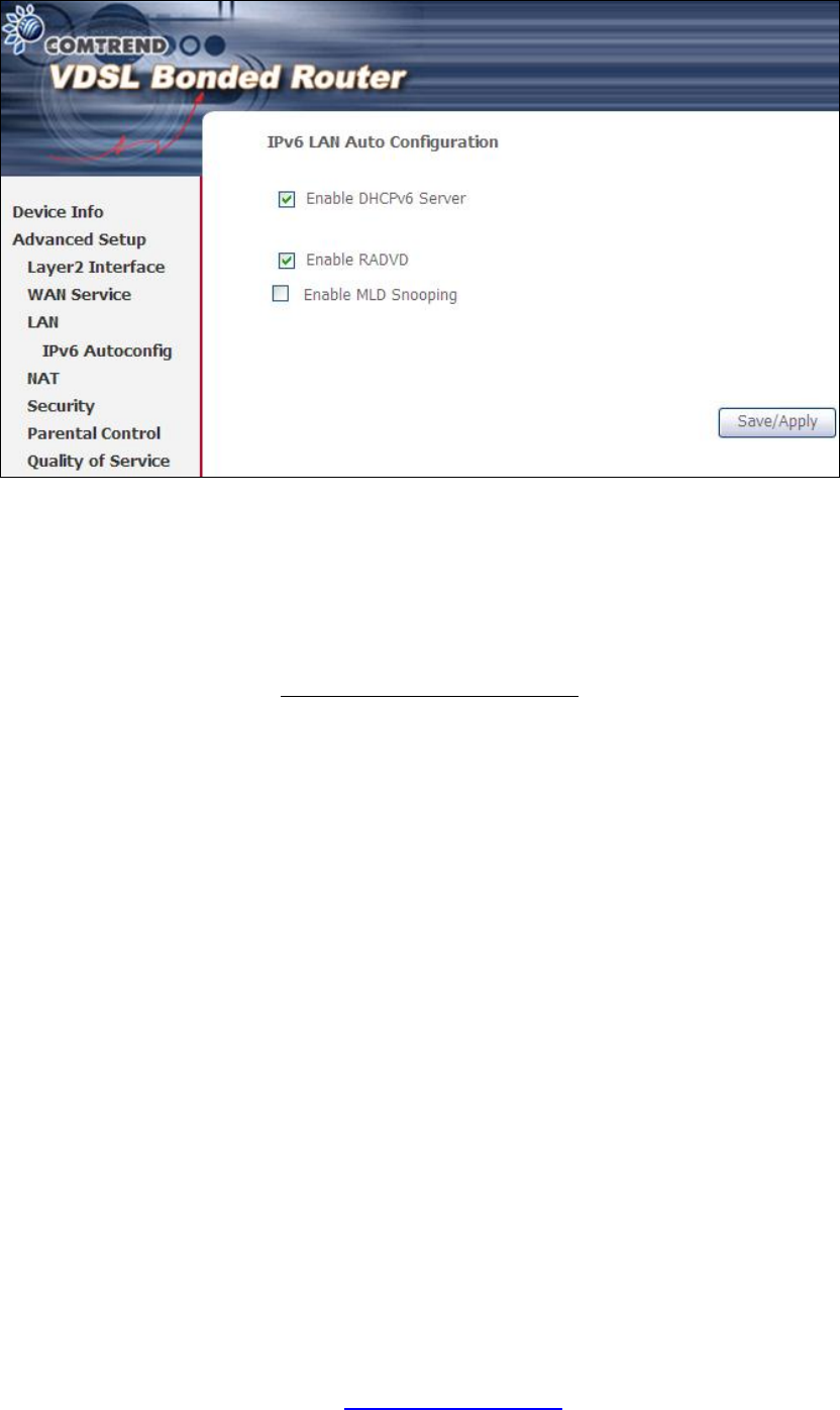
5.4 IPv6 LAN Auto Configuration
Configure the IPv6 LAN Host options (see below) and then click Save/Apply.
DHCPv6 Server: To enable DHCP for IPv6, select the Enable DHCPv6 server
checkbox þ. This setting enables the router to assign IP settings
to every IPv6-capable LAN device (IPv6 clients).
RADVD: Select the checkbox þ to enable the Router ADVertisement Daemon.
This provides information that IPv6 clients can use for autoconfiguration
according to the Neighbour Discovery for IPv6 protocol (RFC2461).
Enable MLD Snooping: Enable by ticking the checkbox þ.
Standard Mode: In standard mode, multicast traffic will flood to all
bridge ports when no client subscribes to a multicast
group – even if snooping is enabled.
Blocking Mode: In blocking mode, the multicast data traffic will be
blocked and not flood to all bridge ports when there are
no client subscriptions to any multicast group.
PDF created with pdfFactory Pro trial version www.pdffactory.com

34
5.5 NAT
To display this option, NAT must be enabled in at least one PVC shown on the
Chapter 5 Advanced Setup.
5.5.1 Virtual Servers
Virtual Servers allow you to direct incoming traffic from the WAN side (identified by
Protocol and External port) to the Internal server with private IP addresses on the
LAN side. The Internal port is required only if the external port needs to be
converted to a different port number used by the server on the LAN side.
A maximum of 32 entries can be configured.
To add a Virtual Server, click Add. The following will be displayed.
Consult the table below for field and header descriptions.
PDF created with pdfFactory Pro trial version www.pdffactory.com

35
Field/Header Description
Use Interface Select a WAN interface from the drop-down box.
Select a Service
Or
Custom Service
User should select the service from the list.
Or
User can enter the name of their choice.
Server IP Address Enter the IP address for the server.
External Port Start Enter the starting external port number (when you select
Custom Server). When a service is selected, the port ranges
are automatically configured.
External Port End Enter the ending external port number (when you select
Custom Server). When a service is selected, the port ranges
are automatically configured.
Protocol TCP, TCP/UDP, or UDP.
Internal Port Start Enter the internal port starting number (when you select
Custom Server). When a service is selected the port ranges
are automatically configured
Internal Port End Enter the internal port ending number (when you select
Custom Server). When a service is selected, the port ranges
are automatically configured.
5.5.2 Port Triggering
Some applications require that specific ports in the firewall be opened for access by
the remote parties. Port Triggers dynamically 'Open Ports' in the firewall when an
application on the LAN initiates a TCP/UDP connection to a remote party using the
'Triggering Ports'. The Router allows the remote party from the WAN side to
establish new connections back to the application on the LAN side using the 'Open
Ports'. A maximum 32 entries can be configured.
To add a Trigger Port, click Add. The following will be displayed.
PDF created with pdfFactory Pro trial version www.pdffactory.com

36
Consult the table below for field and header descriptions.
Field/Header Description
Use Interface Select a WAN interface from the drop-down box.
Select an Application
Or
Custom Application
User should select the application from the list.
Or
User can enter the name of their choice.
Trigger Port Start Enter the starting trigger port number (when you select
custom application). When an application is selected, the
port ranges are automatically configured.
Trigger Port End Enter the ending trigger port number (when you select
custom application). When an application is selected, the
port ranges are automatically configured.
Trigger Protocol TCP, TCP/UDP, or UDP.
Open Port Start Enter the starting open port number (when you select
custom application). When an application is selected, the
port ranges are automatically configured.
Open Port End Enter the ending open port number (when you select
custom application). When an application is selected, the
port ranges are automatically configured.
Open Protocol TCP, TCP/UDP, or UDP.
PDF created with pdfFactory Pro trial version www.pdffactory.com

37
5.5.3 DMZ Host
The DSL router will forward IP packets from the WAN that do not belong to any of
the applications configured in the Virtual Servers table to the DMZ host computer.
To Activate the DMZ host, enter the DMZ host IP address and click Save/Apply.
To Deactivate the DMZ host, clear the IP address field and click Save/Apply.
PDF created with pdfFactory Pro trial version www.pdffactory.com
38
5.6 Security
To display this function, you must enable the firewall feature in WAN Setup.
For detailed descriptions, with examples, please consult Appendix A - Firewall.
5.6.1 IP Filtering
This screen sets filter rules that limit IP traffic (Outgoing/Incoming). Multiple filter
rules can be set and each applies at least one limiting condition. For individual IP
packets to pass the filter all conditions must be fulfilled.
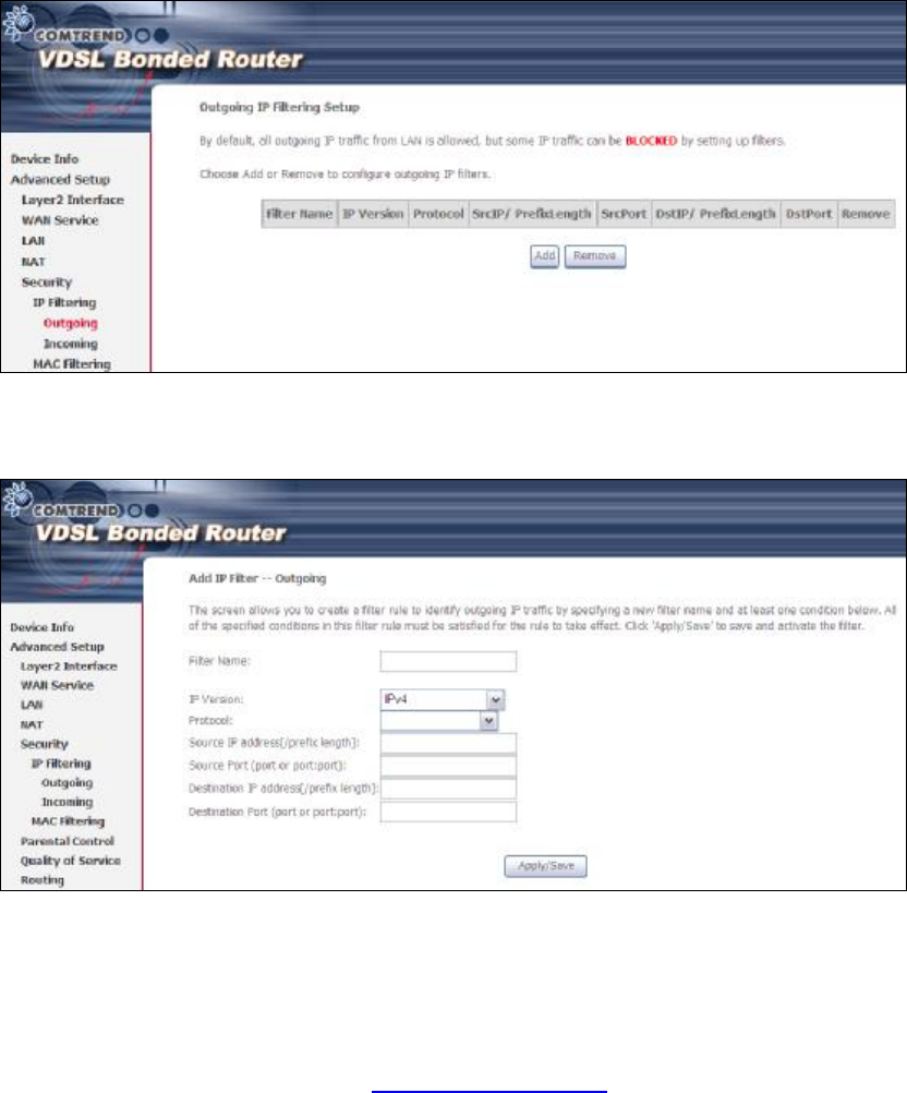
OUTGOING IP FILTER
By default, all outgoing IP traffic is allowed, but IP traffic can be blocked with filters.
To add a filter (to block some outgoing IP traffic), click the Add button.
On the following screen, enter your filter criteria and then click Apply/Save.
Consult the table below for field descriptions.
PDF created with pdfFactory Pro trial version www.pdffactory.com
39
Field Description
Filter Name The filter rule label.
IP Version Select from the drop down menu.
Protocol TCP, TCP/UDP, UDP, or ICMP.
Source IP address Input source IP address.
Source Port (port or port:port) Input source port number or range.
Destination IP address Input destination IP address.
Destination Port (port or port:port)
Input destination port number or range.
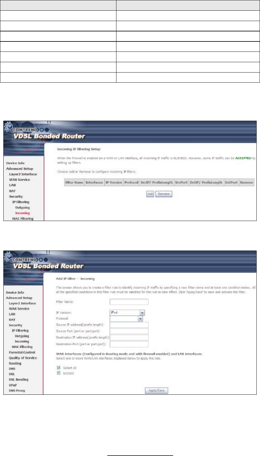
INCOMING IP FILTER
By default, all incoming IP traffic is blocked, but IP traffic can be allowed with filters.
To add a filter (to allow incoming IP traffic), click the Add button.
On the following screen, enter your filter criteria and then click Apply/Save.
Consult the table below for field descriptions.
PDF created with pdfFactory Pro trial version www.pdffactory.com

40
Field Description
Filter Name The filter rule label
IP Version Select from the drop down menu.
Protocol TCP, TCP/UDP, UDP, or ICMP.
Source IP address Enter source IP address.
Source Port (port or port:port) Enter source port number or range.
Destination IP address Enter destination IP address.
Destination Port (port or port:port)
Enter destination port number or range.
At the bottom of this screen, select the WAN and LAN Interfaces to which the filter
rule will apply. You may select all or just a subset. WAN interfaces in bridge mode or
without firewall enabled are not available.
PDF created with pdfFactory Pro trial version www.pdffactory.com
41
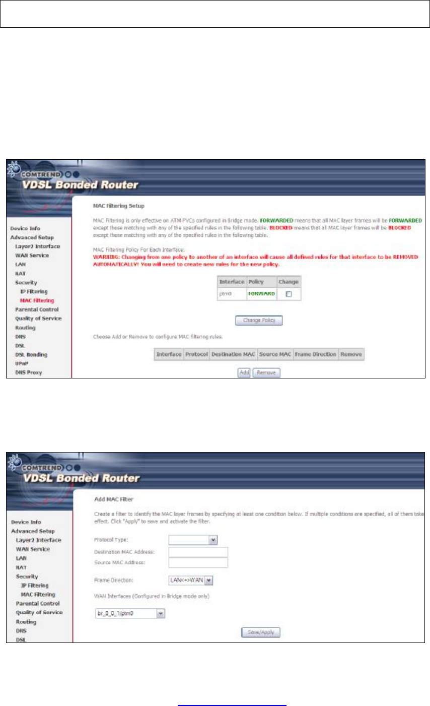
5.6.2 MAC Filtering
NOTE: This option is only available in bridge mode. Other modes use IP Filtering
to perform a similar function.
Each network device has a unique 48-bit MAC address. This can be used to filter
(block or forward) packets based on the originating device. MAC filtering policy and
rules for the NEXUSLINK 3111u can be set according to the following procedure.
The MAC Filtering Global Policy is defined as follows. FORWARDED means that all
MAC layer frames will be FORWARDED except those matching the MAC filter rules.
BLOCKED means that all MAC layer frames will be BLOCKED except those
matching the MAC filter rules. The default MAC Filtering Global policy is
FORWARDED. It can be changed by clicking the Change Policy button.
Choose Add or Remove to configure MAC filtering rules. The following screen will
appear when you click Add. Create a filter to identify the MAC layer frames by
specifying at least one condition below. If multiple conditions are specified, all of
them must be met. Click Save/Apply to save and activate the filter rule.
PDF created with pdfFactory Pro trial version www.pdffactory.com
42
Consult the table below for detailed field descriptions.
Field Description
Protocol Type PPPoE, IPv4, IPv6, AppleTalk, IPX, NetBEUI, IGMP
Destination MAC Address
Defines the destination MAC address
Source MAC Address Defines the source MAC address
Frame Direction Select the incoming/outgoing packet interface
WAN Interfaces Applies the filter to the selected bridge interface.
5.7 Parental Control
This selection provides WAN access control functionality.
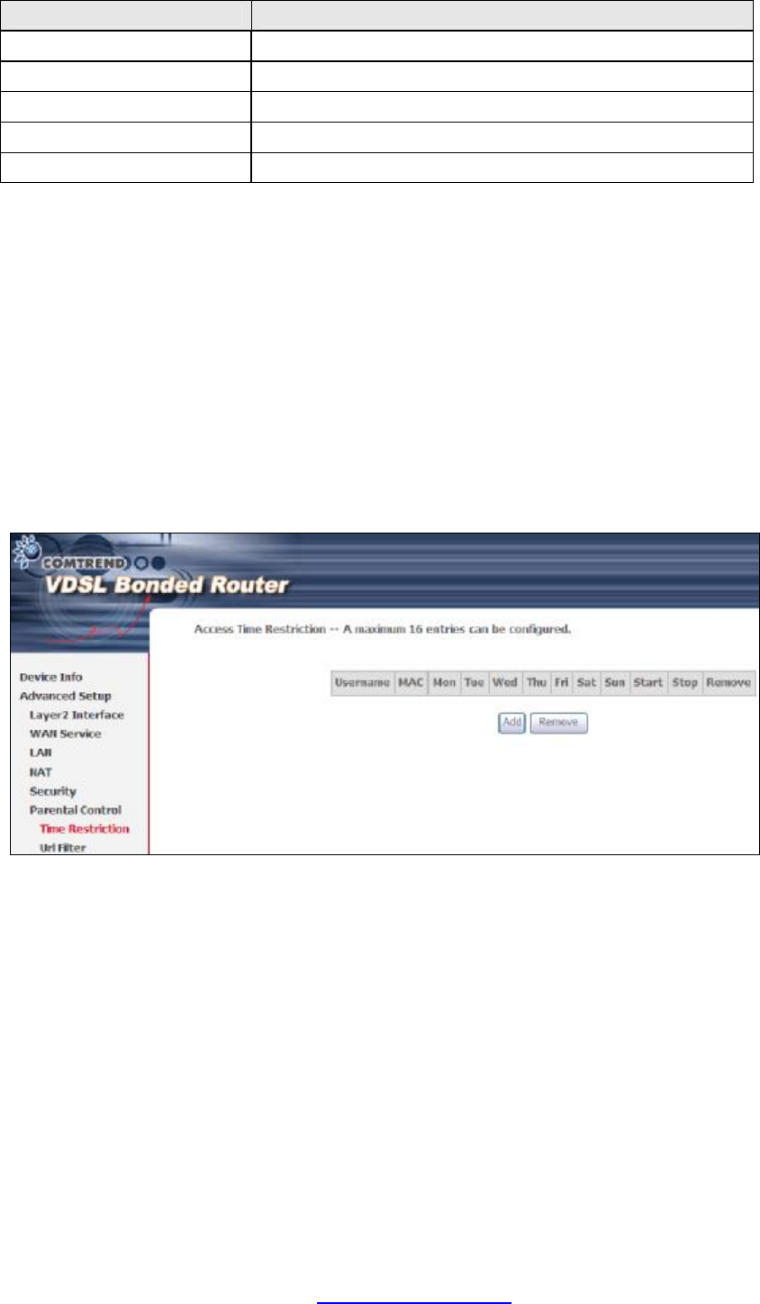
5.7.1 Time Restriction
This feature restricts access from a LAN device to an outside network through the
device on selected days at certain times. Make sure to activate the Internet Time
server synchronization as described in 8.5 Internet Time, so that the scheduled
times match your local time.
Click Add to display the following screen.
PDF created with pdfFactory Pro trial version www.pdffactory.com
43
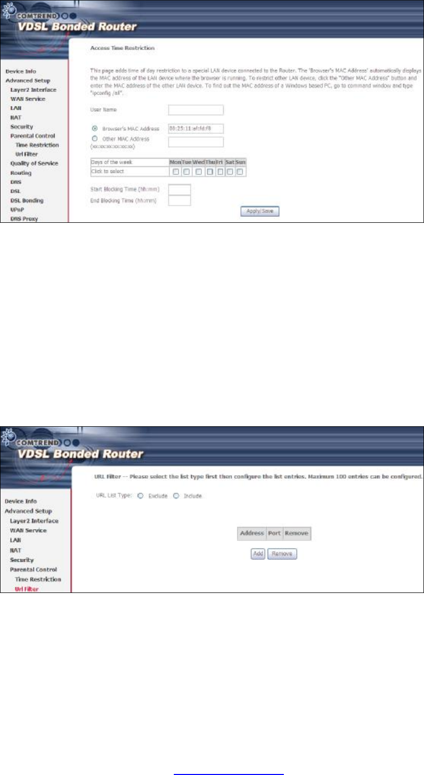
See below for field descriptions. Click Apply/Save to add a time restriction.
User Name: A user-defined label for this restriction.
Browser's MAC Address: MAC address of the PC running the browser.
Other MAC Address: MAC address of another LAN device.
Days of the Week: The days the restrictions apply.
Start Blocking Time: The time the restrictions start.
End Blocking Time: The time the restrictions end.
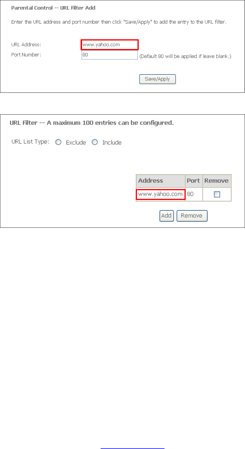
5.7.2 URL Filter
This screen allows for the creation of a filter rule for access rights to websites based
on their URL address and port number.
Click Add to display the following screen.
PDF created with pdfFactory Pro trial version www.pdffactory.com
44
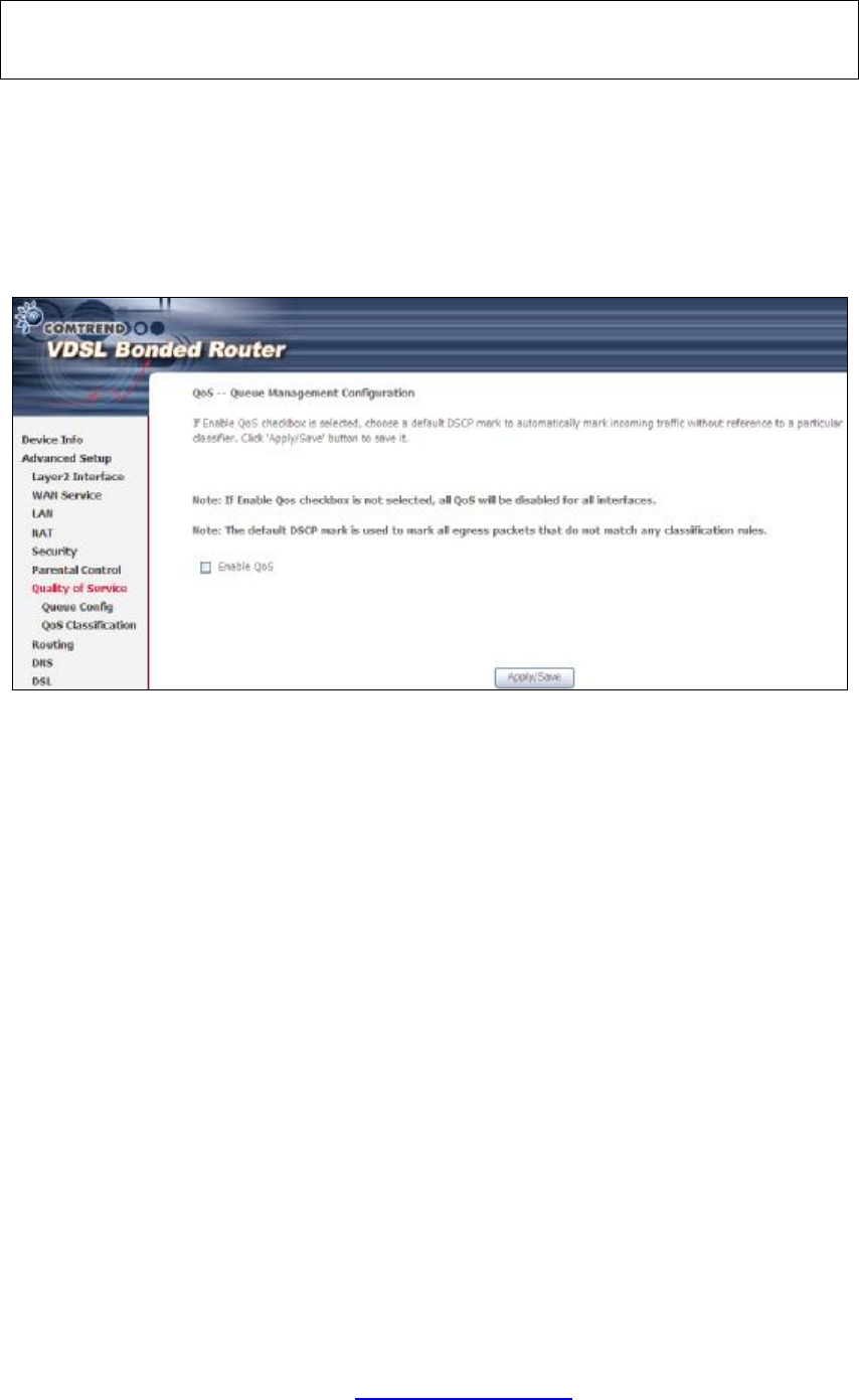
Enter the URL address and port number then click Save/Apply to add the entry to
the URL filter. URL Addresses begin with “www”, as shown in this example.
A maximum of 100 entries can be added to the URL Filter list.
Tick the Exclude radio button to deny access to the websites listed.
Tick the Include radio button to restrict access to only those listed websites.
PDF created with pdfFactory Pro trial version www.pdffactory.com
45
5.8 Quality of Service (QoS)
NOTE: QoS must be enabled in at least one PVC to display this option.
(see Appendix G - Connection Setup for detailed PVC setup instructions).
5.8.1 Queue Management Configuration
To Enable QoS tick the checkbox þ and select a Default DSCP Mark.
Click Apply/Save to activate QoS.
QoS and DSCP Mark are defined as follows:
Quality of Service (QoS): This provides different priority to different users or data
flows, or guarantees a certain level of performance to a data flow in accordance with
requests from Queue Prioritization.
Default Differentiated Services Code Point (DSCP) Mark: This specifies the
per hop behavior for a given flow of packets in the Internet Protocol (IP) header that
do not match any other QoS rule.
PDF created with pdfFactory Pro trial version www.pdffactory.com
46
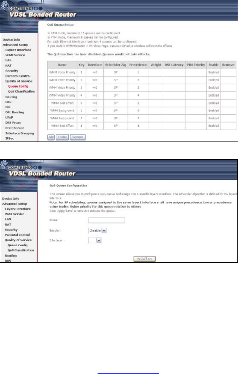
5.8.2 Queue Configuration
This function follows the Differentiated Services rule of IP QoS. You can create a new
Queue entry by clicking the Add button. Enable and assign an interface and
precedence on the next screen. Click Save/Reboot on this screen to activate it.
Click Enable to activate the QoS Queue. Click Add to display the following screen.
Name: Identifier for this Queue entry.
Enable: Enable/Disable the Queue entry.
Interface: Assign the entry to a specific network interface (QoS enabled).
PDF created with pdfFactory Pro trial version www.pdffactory.com
47
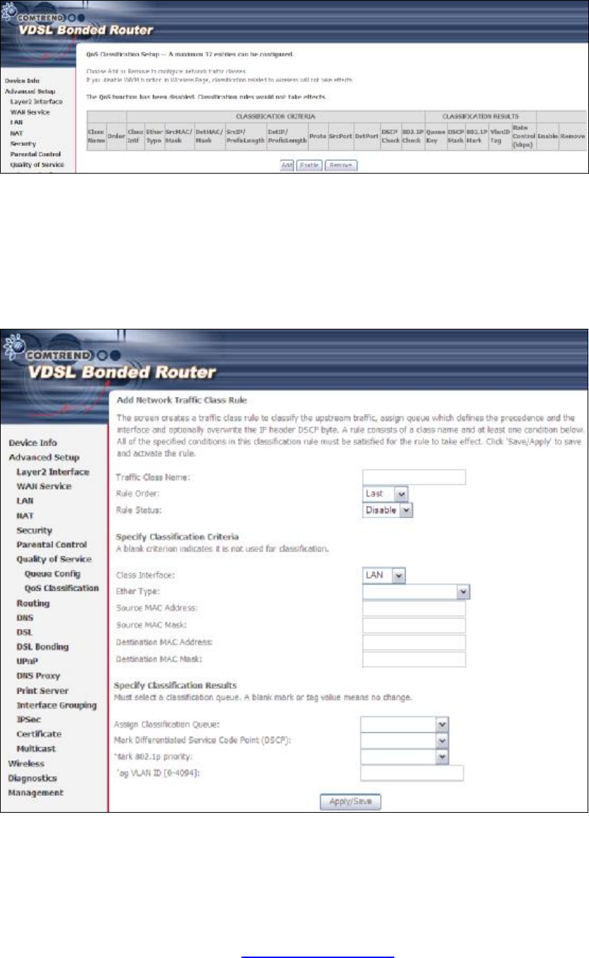
5.8.3 QoS Classification
The network traffic classes are listed in the following table.
Click Add to configure a network traffic class rule and Enable to activate it. To
delete an entry from the list, click Remove.
This screen creates a traffic class rule to classify the upstream traffic, assign
queuing priority and optionally overwrite the IP header DSCP byte. A rule consists of
a class name and at least one logical condition. All the conditions specified in the
rule must be satisfied for it to take effect.
Please see table below for reference.
PDF created with pdfFactory Pro trial version www.pdffactory.com

48
Field Description
Traffic Class Name Enter a name for the traffic class.
Rule Order Last is the only option.
Rule Status Disable or enable the rule.
Classification Criteria
Class Interface Select an interface (i.e. Local, eth0-4, wl0)
Ether Type Set the Ethernet type (e.g. IP, ARP, IPv6).
Source MAC Address A packet belongs to SET-1, if a binary-AND of its source
MAC address with the Source MAC Mask is equal to the
binary-AND of the Source MAC Mask and this field.
Source MAC Mask This is the mask used to decide how many bits are checked
in Source MAC Address.
Destination MAC
Address A packet belongs to SET-1 then the result that the
Destination MAC Address of its header binary-AND to the
Destination MAC Mask must equal to the result that this
field binary-AND to the Destination MAC Mask.
Destination MAC Mask
This is the mask used to decide how many bits are checked
in Destination MAC Address.
Classification Results
Assign Classification
Queue The queue configurations are presented in this format:
“Interfacename&Prece P&Queue Q” where P and Q are the
Precedence and Queue Key values for the corresponding
Interface as listed on the Queue Config screen.
Mark Differentiated
Service Code Point The selected Code Point gives the corresponding priority to
packets that satisfy the rule.
Mark 802.1p Priority Select between 0-7. Lower values have higher priority.
Tag VLAN ID Enter a 802.1Q VLAN ID tag [2-4094]
PDF created with pdfFactory Pro trial version www.pdffactory.com
49
5.9 Routing
These following routing functions are accessed from this menu:
Default Gateway, Static Route, Policy Routing, RIP and IPv6 Static Route.
NOTE: In bridge mode, the RIP menu option is hidden while the other menu
options are shown but ineffective.
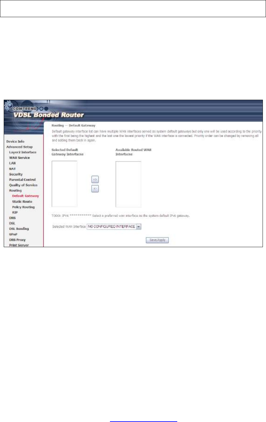
5.9.1 Default Gateway
Default gateway interface list can have multiple WAN interfaces served as system
default gateways but only one will be used according to the priority with the first
being the highest and the last one the lowest priority if the WAN interface is
connected. Priority order can be changed by removing all and adding them back in
again.
PDF created with pdfFactory Pro trial version www.pdffactory.com
50
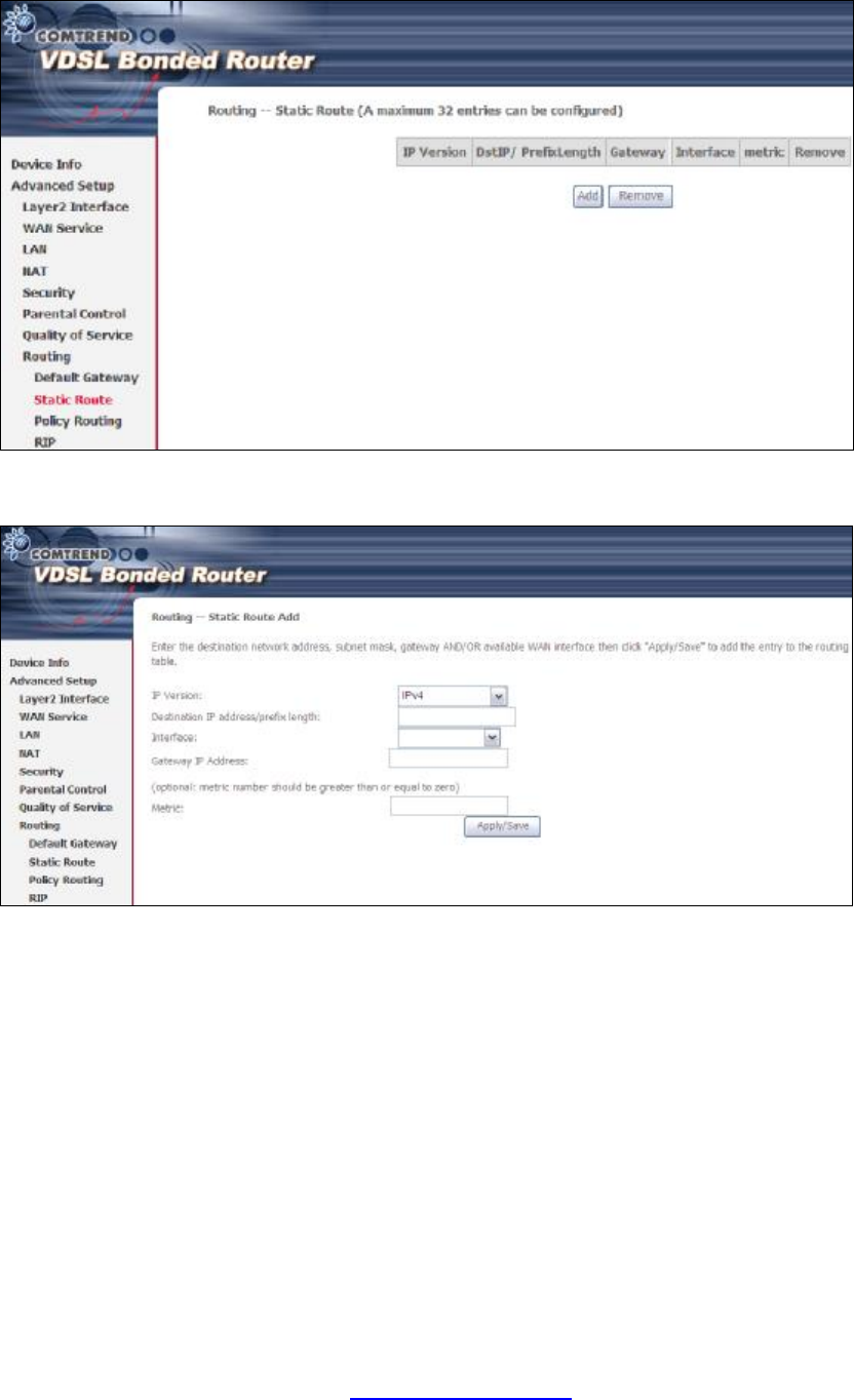
5.9.2 Static Route
This option allows for the configuration of static routes by destination IP.
Click Add to create a static route or click Remove to delete a static route.
After clicking Add the following screen will display.
Select the IP Version from the drop down menu. Input the Destination IP Address,
select the interface and input the Gateway IP Address. Then click Apply/Save to
add an entry to the routing table.
PDF created with pdfFactory Pro trial version www.pdffactory.com
51
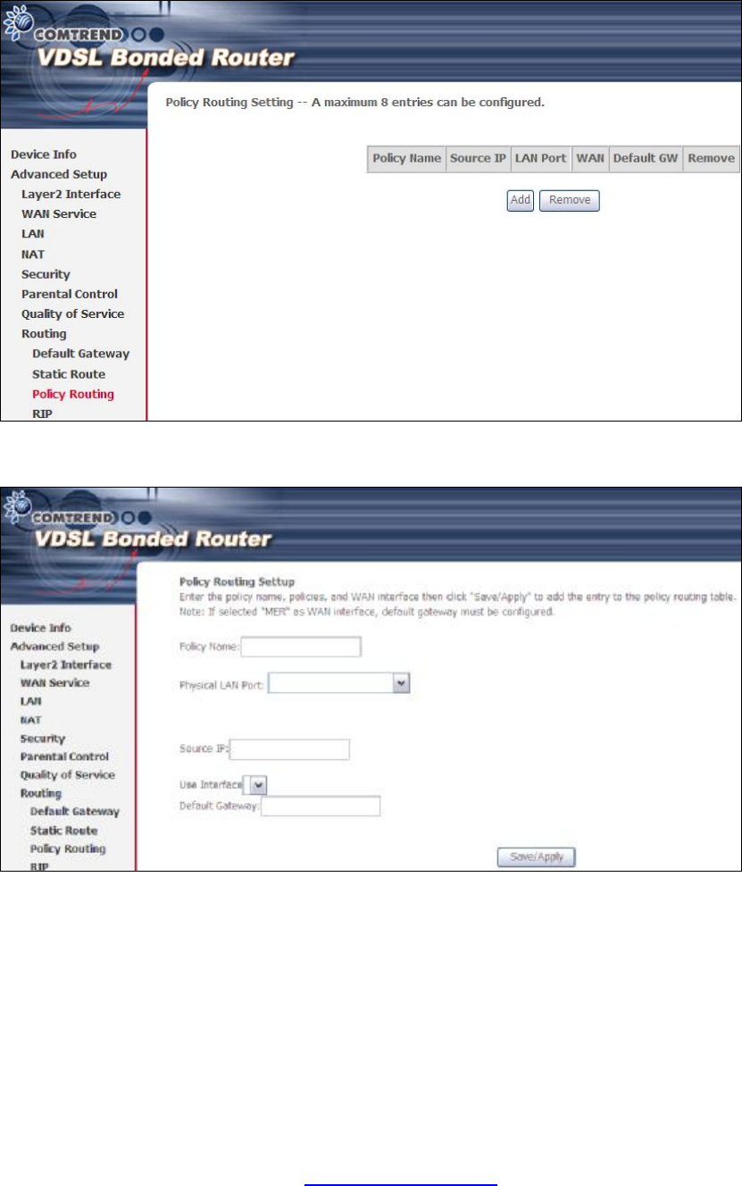
5.9.3 Policy Routing
This option allows for the configuration of static routes by policy.
Click Add to create a routing policy or Remove to delete one.
On the following screen, complete the form and click Save/Apply to create a policy.
PDF created with pdfFactory Pro trial version www.pdffactory.com

53
5.10 DNS
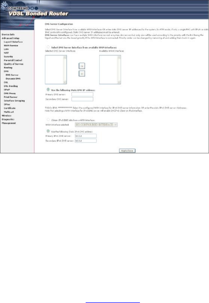
5.10.1 DNS Server
Select DNS Server Interface from available WAN interfaces OR enter static DNS
server IP addresses for the system. In ATM mode, if only a single PVC with IPoA or
static IPoE protocol is configured, Static DNS server IP addresses must be entered.
Click Apply/Save to save the new configuration.
PDF created with pdfFactory Pro trial version www.pdffactory.com
54
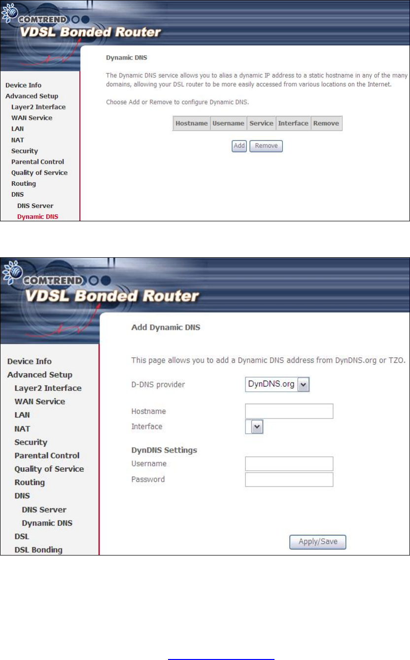
5.10.2 Dynamic DNS
The Dynamic DNS service allows you to map a dynamic IP address to a static
hostname in any of many domains, allowing the NEXUSLINK 3111u to be more
easily accessed from various locations on the Internet.
To add a dynamic DNS service, click Add. The following screen will display.
Consult the table below for field descriptions.
PDF created with pdfFactory Pro trial version www.pdffactory.com

55
Field Description
D-DNS provider Select a dynamic DNS provider from the list
Hostname Enter the name of the dynamic DNS server
Interface Select the interface from the list
Username Enter the username of the dynamic DNS server
Password Enter the password of the dynamic DNS server
PDF created with pdfFactory Pro trial version www.pdffactory.com
56
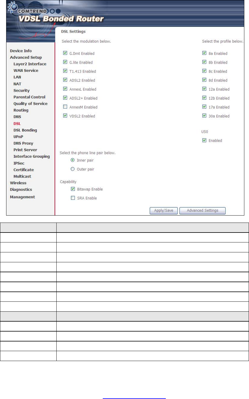
5.11 DSL
The DSL Settings screen allows for the selection of DSL modulation modes.
For optimum performance, the modes selected should match those of your ISP.
DSL Mode Data Transmission Rate - Mbps (Megabits per second)
G.Dmt Downstream: 12 Mbps Upstream: 1.3 Mbps
G.lite Downstream: 4 Mbps Upstream: 0.5 Mbps
T1.413 Downstream: 8 Mbps Upstream: 1.0 Mbps
ADSL2 Downstream: 12 Mbps Upstream: 1.0 Mbps
AnnexL Supports longer loops but with reduced transmission rates
ADSL2+ Downstream: 24 Mbps Upstream: 1.0 Mbps
AnnexM Downstream: 24 Mbps Upstream: 3.5 Mbps
MULTI-DSL Downstream: 100 Mbps Upstream: 60 Mbps
Options Description
Inner/Outer Pair
Select the inner or outer pins of the twisted pair (RJ11 cable)
Bitswap Enable Enables adaptive handshaking functionality
SRA Enable Enables Seamless Rate Adaptation (SRA)
Profile Selection 8a-d, 12a-b, 17a, 30a, US0
PDF created with pdfFactory Pro trial version www.pdffactory.com
57
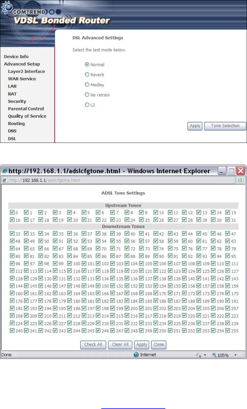
Advanced DSL Settings
Click Advanced Settings to reveal additional options. On the following screen you
can select a test mode or modify tones by clicking Tone Selection. Click Apply to
implement these settings and return to the previous screen.
On this screen you select the tones you want activated, then click Apply and Close.
PDF created with pdfFactory Pro trial version www.pdffactory.com
60
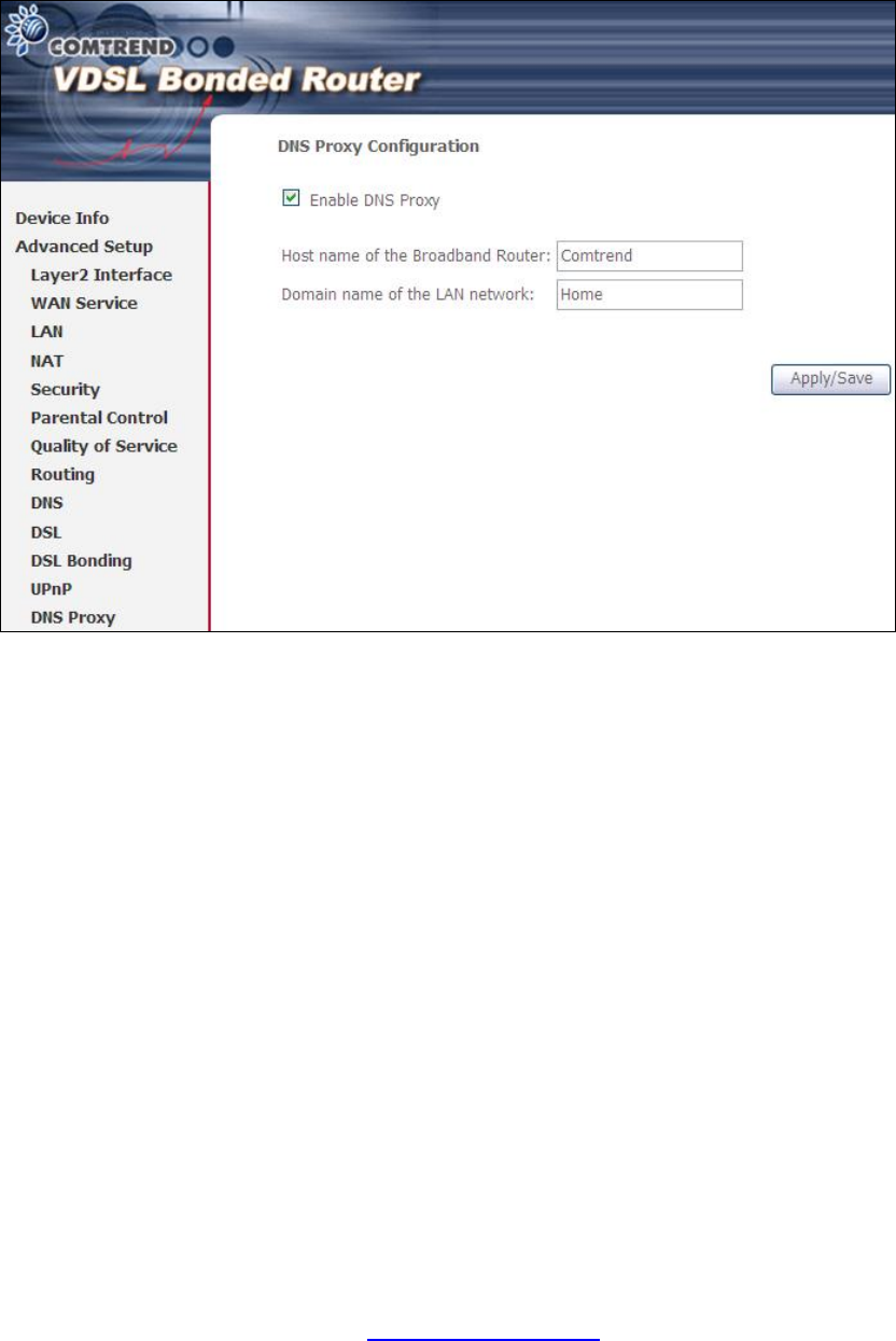
5.14 DNS Proxy
DNS proxy receives DNS queries and forwards DNS queries to the Internet. After the
CPE gets answers from the DNS server, it replies to the LAN clients. Configure DNS
proxy with the default setting, when the PC gets an IP via DHCP, the domain name,
Home, will be added to PC’s DNS Suffix Search List, and the PC can access route with
“Comtrend.Home”.
PDF created with pdfFactory Pro trial version www.pdffactory.com
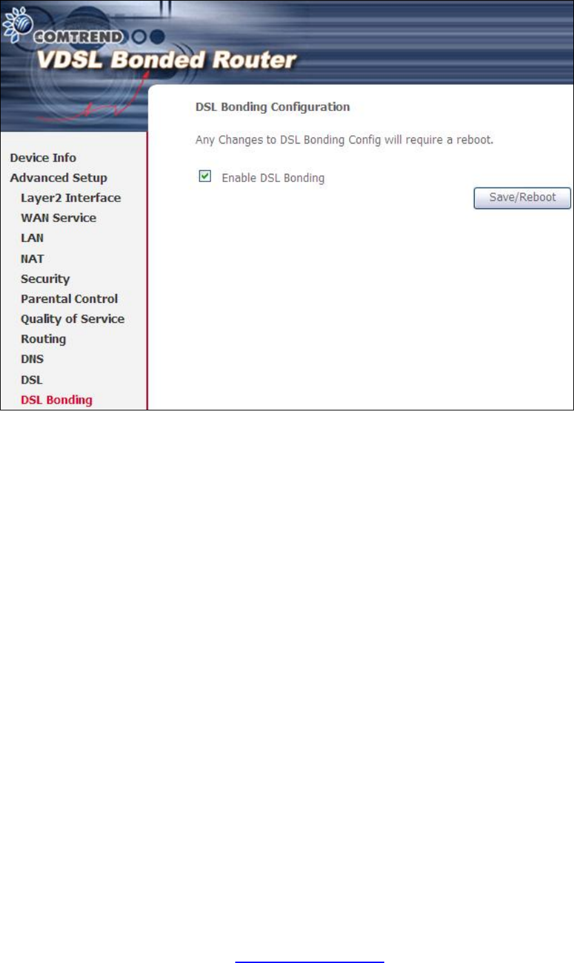
62
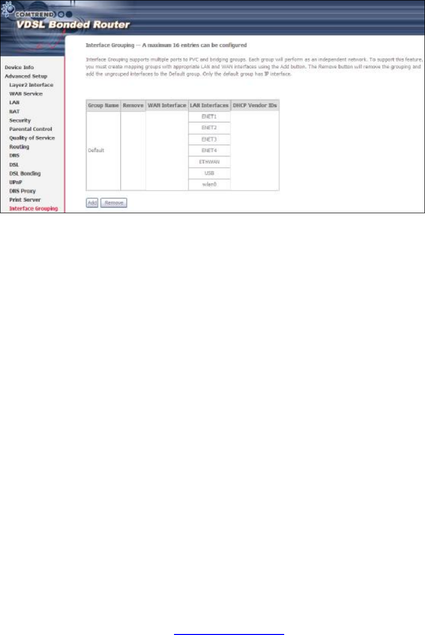
5.16 Interface Grouping
Interface Grouping supports multiple ports to PVC and bridging groups. Each group
performs as an independent network. To use this feature, you must create mapping
groups with appropriate LAN and WAN interfaces using the Add button.
The Remove button removes mapping groups, returning the ungrouped interfaces
to the Default group. Only the default group has an IP interface.
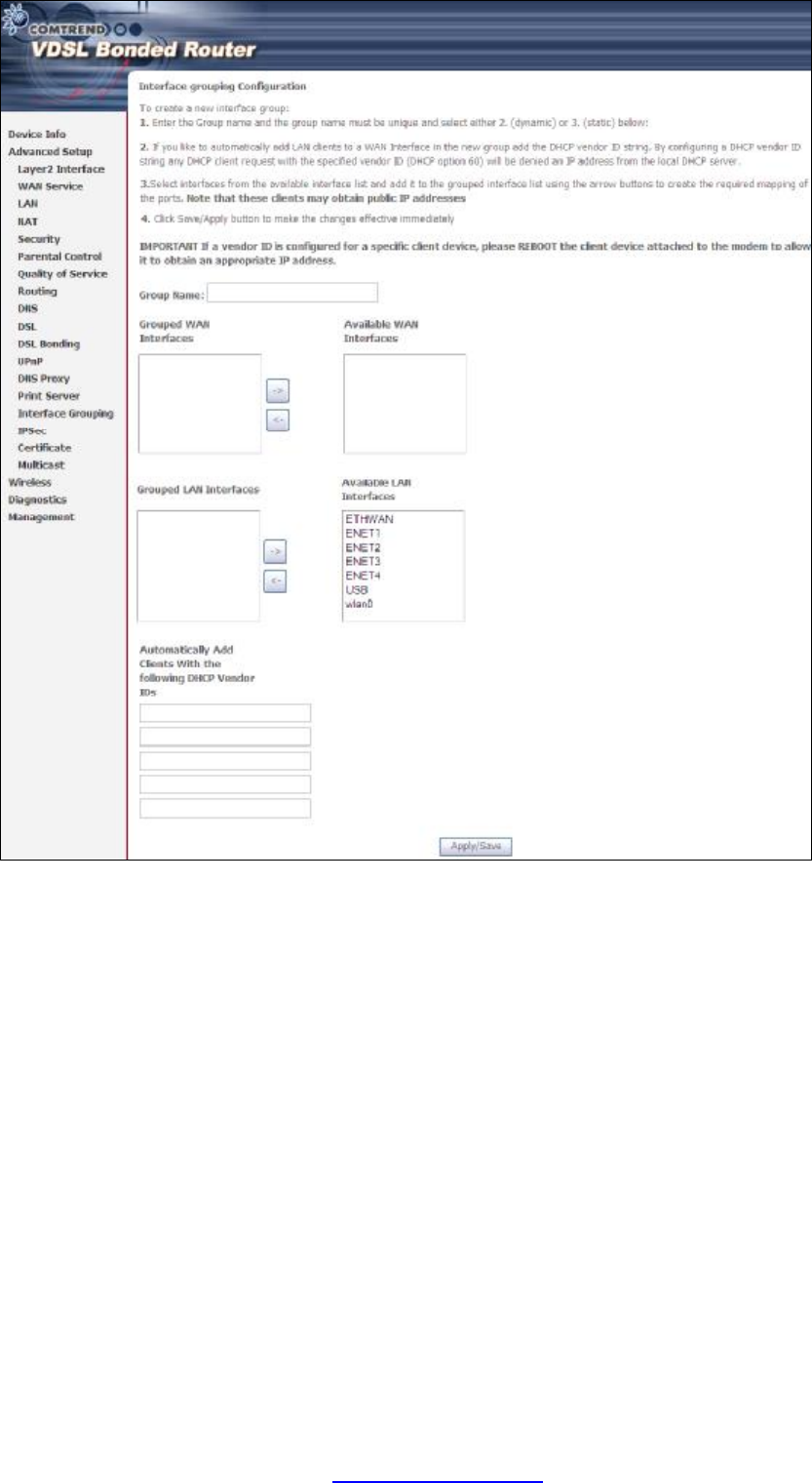
To add an Interface Group, click the Add button. The following screen will appear.
It lists the available and grouped interfaces. Follow the instructions shown
onscreen.
PDF created with pdfFactory Pro trial version www.pdffactory.com
63
Automatically Add Clients With Following DHCP Vendor IDs:
Add support to automatically map LAN interfaces to PVC's using DHCP vendor ID
(option 60). The local DHCP server will decline and send the requests to a remote
DHCP server by mapping the appropriate LAN interface. This will be turned on when
Interface Grouping is enabled.
For example, imagine there are 4 PVCs (0/33, 0/36, 0/37, 0/38). VPI/VCI=0/33 is
for PPPoE while the other PVCs are for IP set-top box (video). The LAN interfaces are
ENET1, ENET2, ENET3, and ENET4.
The Interface Grouping configuration will be:
1. Default: ENET1, ENET2, ENET3, and ENET4.
2. Video: nas_0_36, nas_0_37, and nas_0_38. The DHCP vendor ID is "Video".
If the onboard DHCP server is running on "Default" and the remote DHCP server is
running on PVC 0/36 (i.e. for set-top box use only). LAN side clients can get IP
addresses from the CPE's DHCP server and access the Internet via PPPoE (0/33).
PDF created with pdfFactory Pro trial version www.pdffactory.com
64
If a set-top box is connected to ENET1 and sends a DHCP request with vendor ID
"Video", the local DHCP server will forward this request to the remote DHCP server.
The Interface Grouping configuration will automatically change to the following:
1. Default: ENET2, ENET3, and ENET4.
2. Video: nas_0_36, nas_0_37, nas_0_38, and ENET1.
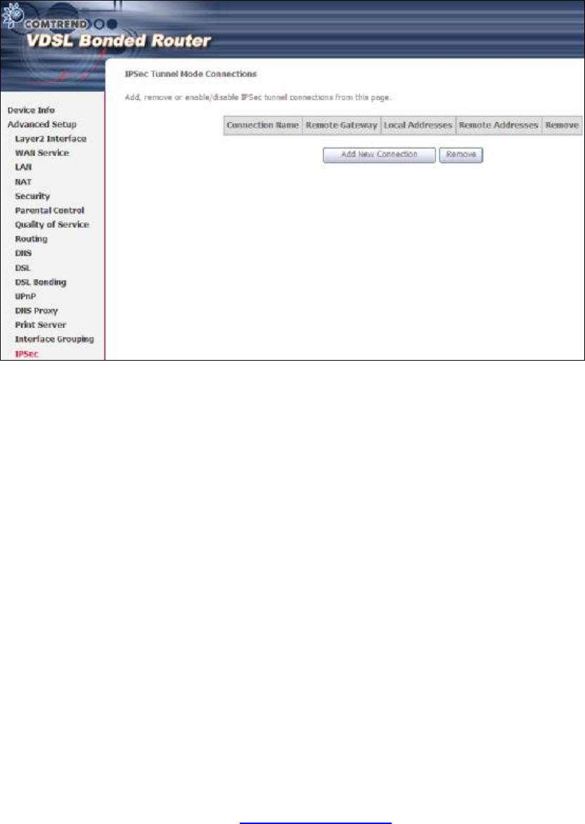
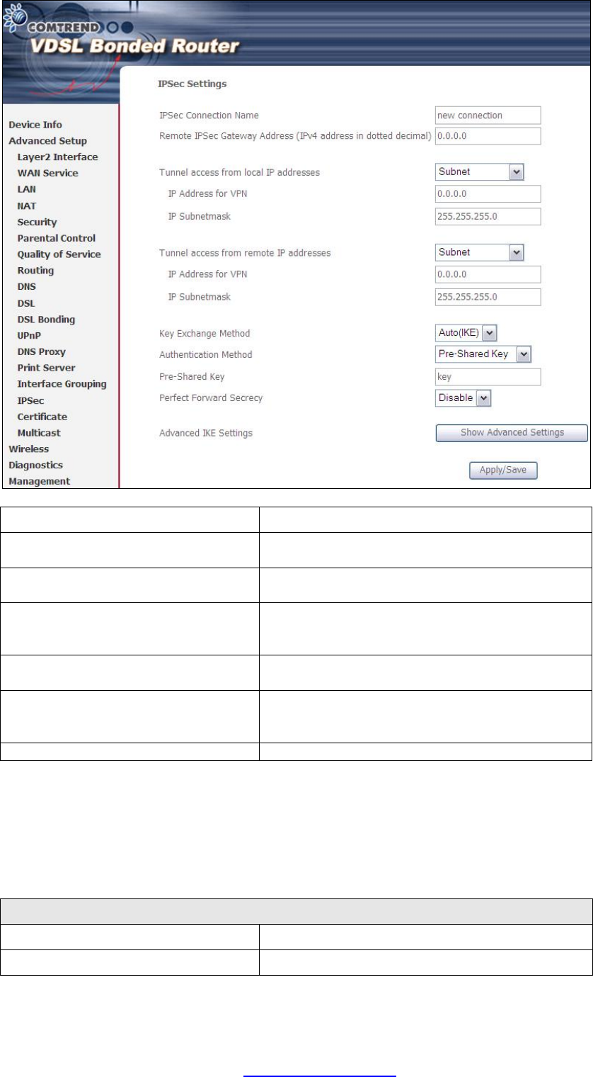
5.17 IP Sec
You can add, edit or remove IPSec tunnel mode connections from this page.
Click Add New Connection to add a new IPSec termination rule.
The following screen will display.
PDF created with pdfFactory Pro trial version www.pdffactory.com
65
IPSec Connection Name User-defined label
Remote IPSec Gateway Address The location of the Remote IPSec Gateway. IP
address or domain name can be used.
Tunnel access from local IP
addresses Specify the acceptable host IP on the local
side. Choose Single or Subnet.
IP Address/Subnet Mask for VPN If you chose Single, please enter the host IP
address for VPN. If you chose Subnet
, please
enter the subnet information for VPN.
Tunnel access from remote IP
addresses Specify the acceptable host IP on the remote
side. Choose Single or Subnet.
IP Address/Subnet Mask for VPN If you chose Single, please enter the host IP
address for VPN. If you chose Subnet
, please
enter the subnet information for VPN.
Key Exchange Method Select from Auto(IKE) or Manual
For the Auto(IKE) key exchange method, select Pre-shared key or Certificate (X.509)
authentication. For Pre-shared key authentication you must enter a key, while for
Certificate (X.509) authentication you must select a certificate from the list.
See the tables below for a summary of all available options.
Auto(IKE) Key Exchange Method
Pre-Shared Key / Certificate (X.509)
Input Pre-shared key / Choose Certificate
Perfect Forward Secrecy Enable or Disable
PDF created with pdfFactory Pro trial version www.pdffactory.com
66
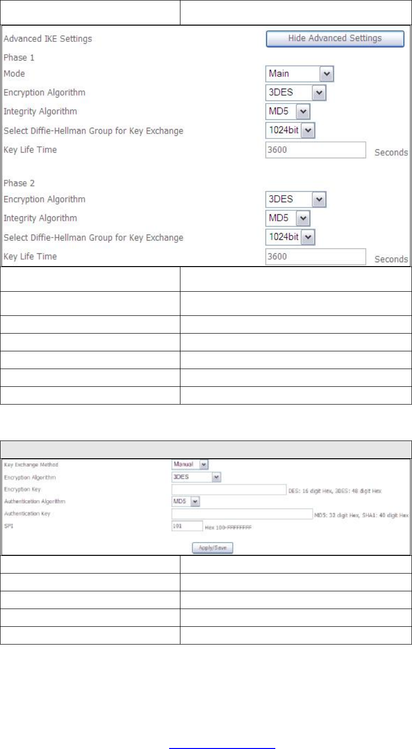
Advanced IKE Settings Select Show Advanced Settings to reveal
the advanced settings options shown below.
Advanced IKE Settings Select Hide Advanced Settings to hide the
advanced settings options shown above.
Phase 1 / Phase 2 Choose settings for each phase, the available
options are separated with a “/” character.
Mode Main / Aggressive
Encryption Algorithm DES / 3DES / AES 128,192,256
Integrity Algorithm MD5 / SHA1
Select Diffie-Hellman Group 768 – 8192 bit
Key Life Time Enter your own or use the default (1 hour)
The Manual key exchange method options are summarized in the table below.
Manual Key Exchange Method
Encryption Algorithm DES / 3DES / AES (aes-cbc)
Encryption Key DES: 16 digit Hex, 3DES: 48 digit Hex
Authentication Algorithm MD5 / SHA1
Authentication Key MD5: 32 digit Hex, SHA1: 40 digit Hex
SPI (default is 101) Enter a Hex value from 100-FFFFFFFF
PDF created with pdfFactory Pro trial version www.pdffactory.com
67
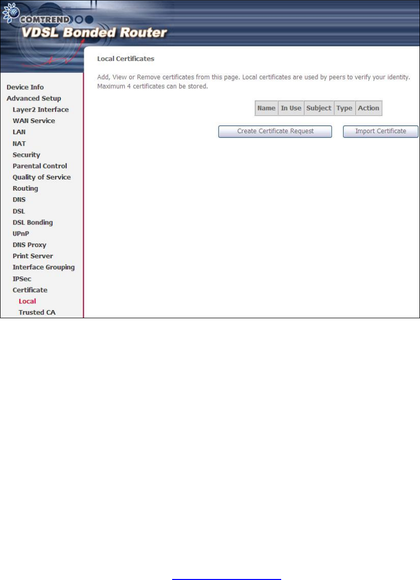
5.18 Certificate
A certificate is a public key, attached with its owner’s information (company name,
server name, personal real name, contact e-mail, postal address, etc) and digital
signatures. There will be one or more digital signatures attached to the certificate,
indicating that these entities have verified that this certificate is valid.
5.18.1 Local
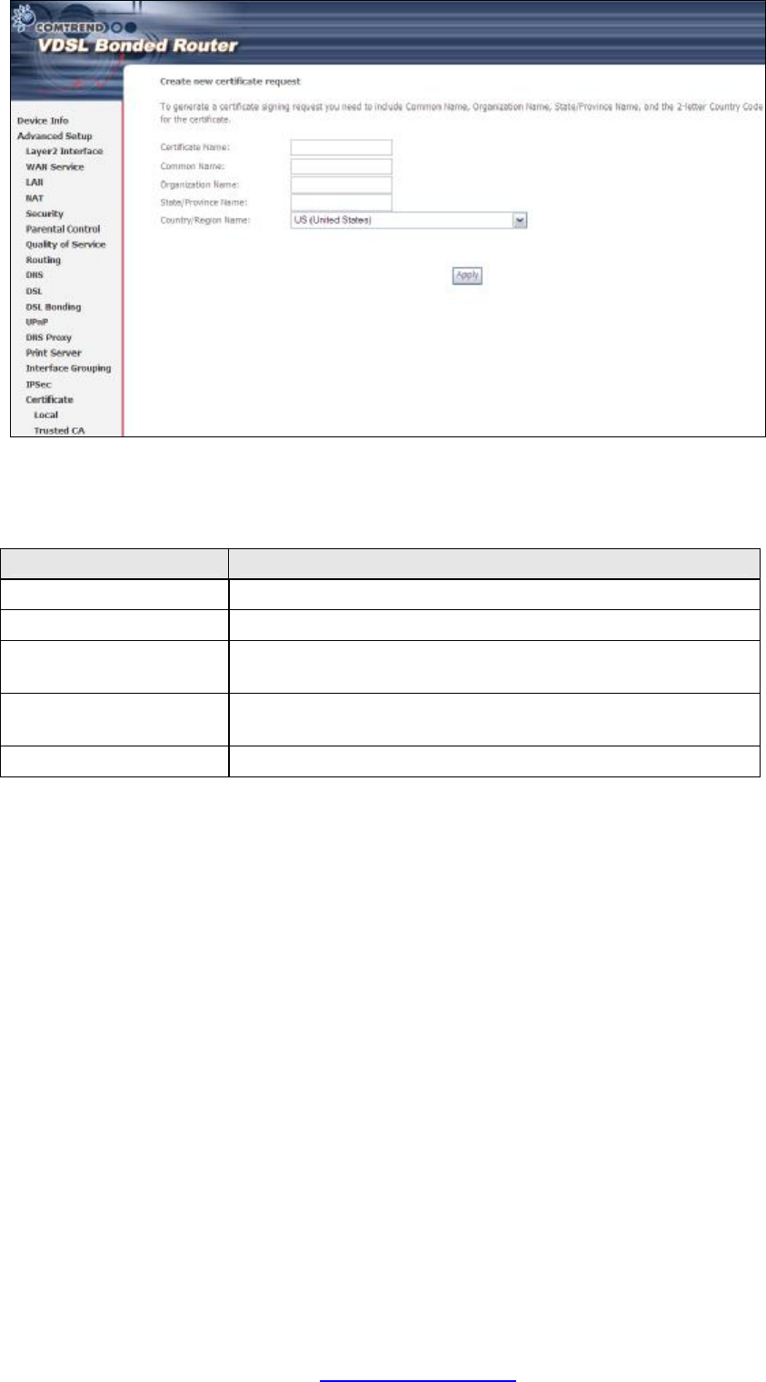
CREATE CERTIFICATE REQUEST
Click Create Certificate Request to generate a certificate-signing request.
The certificate-signing request can be submitted to the vendor/ISP/ITSP to apply for
a certificate. Some information must be included in the certificate-signing request.
Your vendor/ISP/ITSP will ask you to provide the information they require and to
provide the information in the format they regulate. Enter the required information
and click Apply to generate a private key and a certificate-signing request.
PDF created with pdfFactory Pro trial version www.pdffactory.com
68
The following table is provided for your reference.
Field Description
Certificate Name A user-defined name for the certificate.
Common Name Usually, the fully qualified domain name for the machine
.
Organization Name The exact legal name of your organization.
Do not abbreviate.
State/Province Name The state or province where your organization is located
.
It cannot be abbreviated.
Country/Region Name The two-letter ISO abbreviation for your country.
PDF created with pdfFactory Pro trial version www.pdffactory.com
69
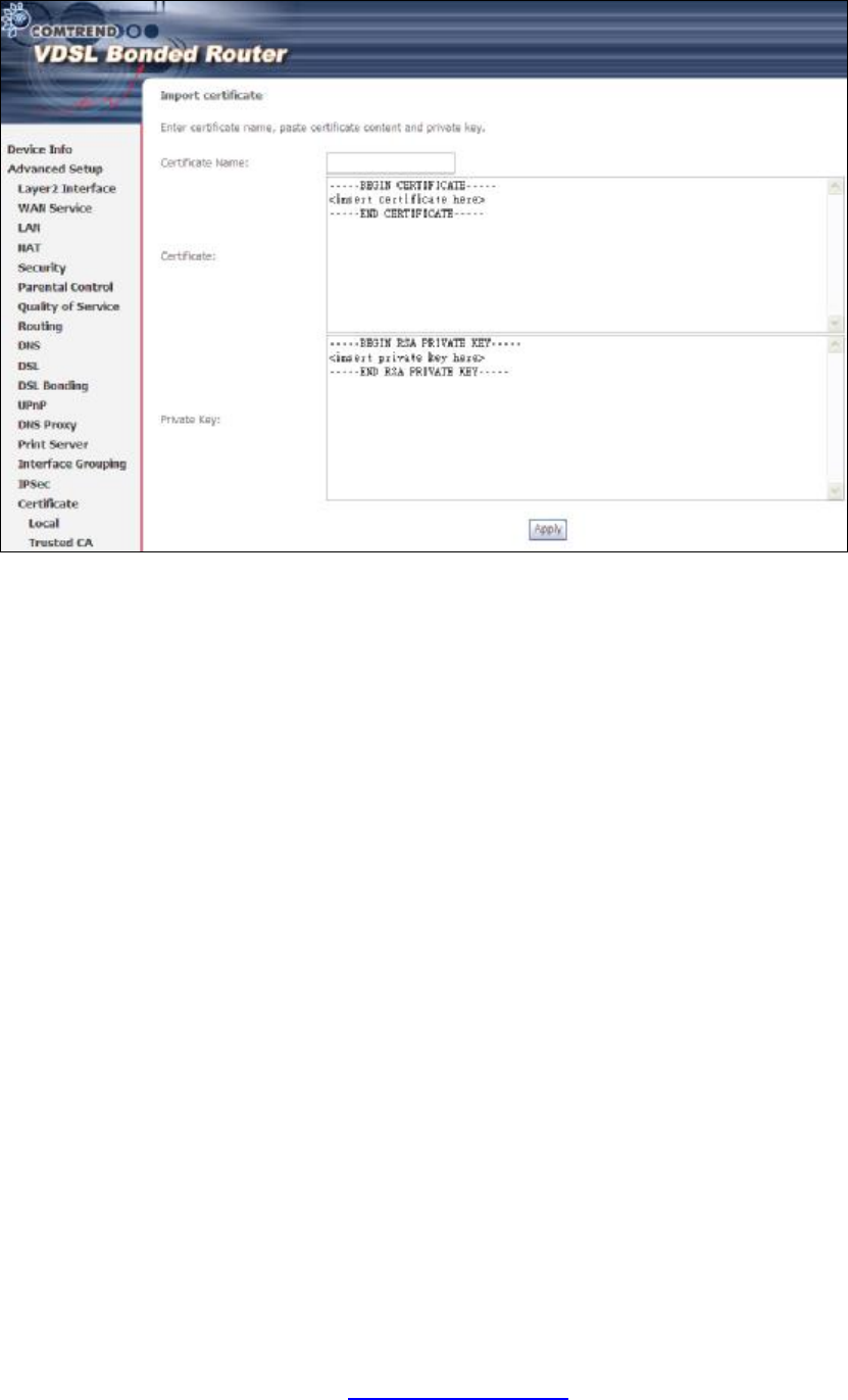
IMPORT CERTIFICATE
Click Import Certificate to paste the certificate content and the private key
provided by your vendor/ISP/ITSP into the corresponding boxes shown below.
Input a certificate name and click Apply to import the local certificate.
PDF created with pdfFactory Pro trial version www.pdffactory.com
70
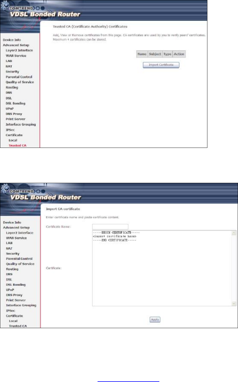
5.18.2 Trusted CA
CA is an abbreviation for Certificate Authority, which is a part of the X.509 system.
It is itself a certificate, attached with the owner information of this certificate
authority; but its purpose is not encryption/decryption. Its purpose is to sign and
issue certificates, in order to prove that these certificates are valid.
Click Import Certificate to paste the certificate content of your trusted CA. The
CA certificate content will be provided by your vendor/ISP/ITSP and is used to
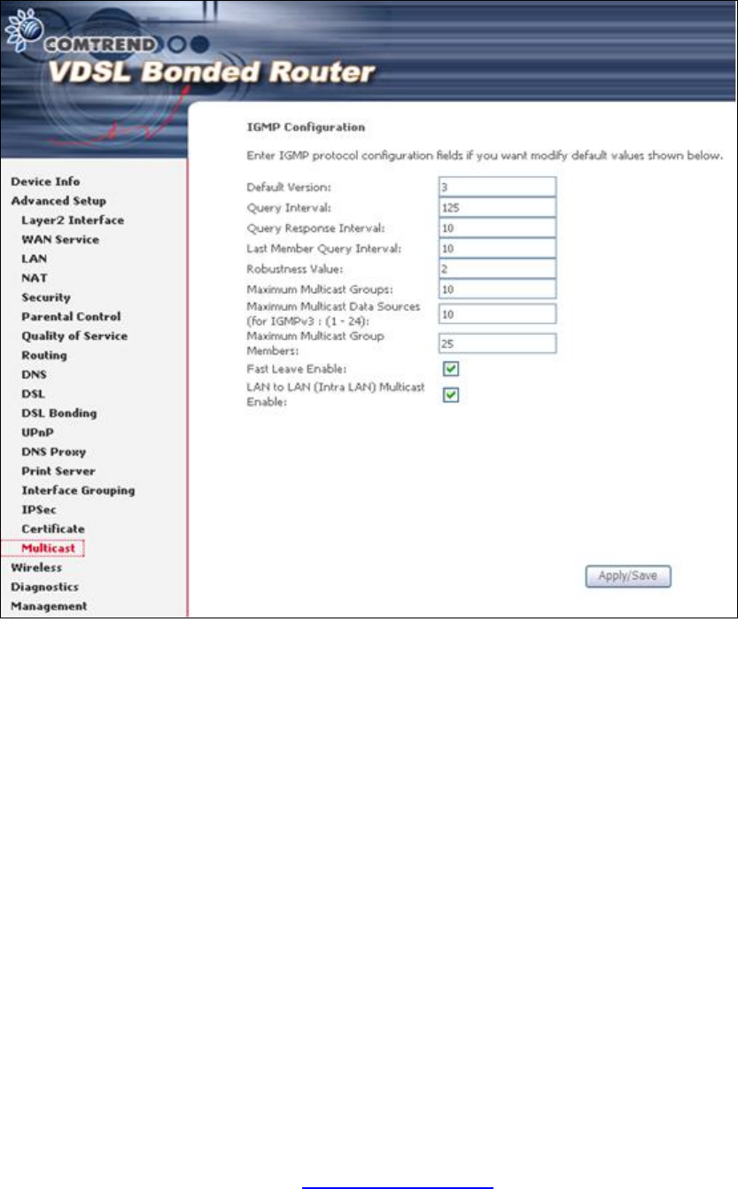
authenticate the Auto-Configuration Server (ACS) that the CPE will connect to.
Input a certificate name and click Apply to import the CA certificate.
PDF created with pdfFactory Pro trial version www.pdffactory.com
72
Chapter 6 Wireless
The Wireless menu provides access to the wireless options discussed below.
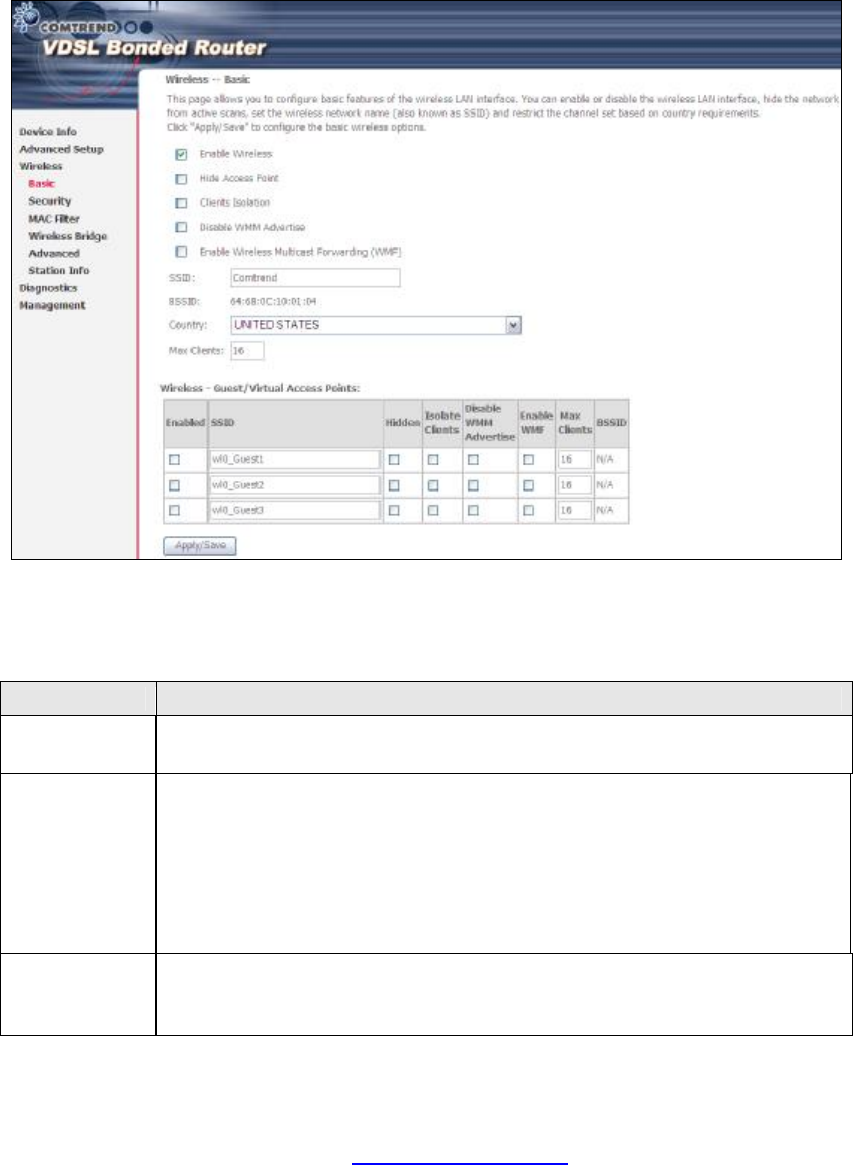
6.1 Basic
The Basic option allows you to configure basic features of the wireless LAN interface.
Among other things, you can enable or disable the wireless LAN interface, hide the
network from active scans, set the wireless network name (also known as SSID)
and restrict the channel set based on country requirements.
Click Save/Apply to apply the selected wireless options.
Consult the table below for descriptions of these options.
Option Description
Enable
Wireless A checkbox þ that enables or disables the wireless LAN interface.
When selected, a set of basic wireless options will appear.
Hide Access
Point Select Hide Access Point to protect the access point from detection
by wireless active scans. To check AP status in Windows XP, open
Network Connections from the start Menu and select View
Available Network Connections. If the access point is hidden, it
will not be listed there. To connect a client to a hidden access point,
the station must add the access point manually to its wireless
configuration.
Clients
Isolation When enabled, it prevents client PCs from seeing one another in My
Network Places or Network Neighborhood. Also, prevents one
wireless client communicating with another wireless client.
PDF created with pdfFactory Pro trial version www.pdffactory.com

73
Option Description
Disable WMM
Advertise
Stops the router from ‘advertising’ its Wireless Multimedia (WMM)
functionality, which provides basic quality of service for
time-sensitive applications (e.g. VoIP, Video).
Enable
Wireless
Multicast
Forwarding
Select the checkbox þ to enable this function.
SSID
[1-32
characters]
Sets the wireless network name. SSID stands for Service Set
Identifier. All stations must be configured with the correct SSID to
access the WLAN. If the SSID does not match, that user will not be
granted access.
BSSID The BSSID is a 48-bit identity used to identify a particular BSS
(Basic Service Set) within an area. In Infrastructure BSS
networks, the BSSID is the MAC (Media Access Control) address of
the AP (Access Point); and in Independent BSS or ad hoc networks,
the BSSID is generated randomly.
Country A drop-down menu that permits worldwide and specific national
settings. Local regulations limit channel range:
US= worldwide, Japan=1-14, Jordan= 10-13, Israel= 1-13
Max Clients The maximum number of clients that can access the router.
Wireless -
Guest /
Virtual
Access Points
This router supports multiple SSIDs called Guest SSIDs or Virtual
Access Points. To enable one or more Guest SSIDs select the
checkboxes þ in the Enabled column. To hide a Guest SSID, select
its checkbox þ in the Hidden column.
Do the same for Isolate Clients and Disable WMM Advertise.
For a description of these two functions, see the previous entries for
“Clients Isolation” and “Disable WMM Advertise”. Similarly, for
Enable WMF, Max Clients and BSSID, consult the matching
entries in this table.
NOTE: Remote wireless hosts cannot scan Guest SSIDs.
PDF created with pdfFactory Pro trial version www.pdffactory.com
74
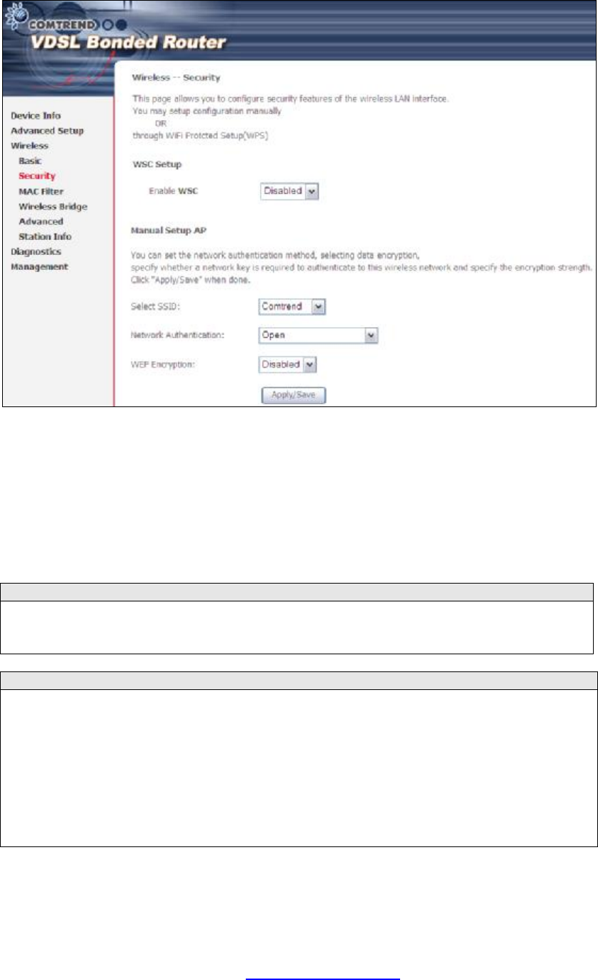
6.2 Security
The following screen appears when Wireless Security is selected. The options shown
here allow you to configure security features of the wireless LAN interface.
Click Save/Apply to implement new configuration settings.
WIRELESS SECURITY
Wireless security settings can be configured according to Wi-Fi Protected Setup
(WPS) or Manual Setup. The WPS method configures security settings automatically
(see 6.2.1 WPS) while the Manual Setup method requires that the user configure
these settings using the Web User Interface (see the table below).
Select SSID
Select the wireless network name from the drop-
down box. SSID stands for Service
Set Identifier. All stations must be configured with the correct SSID to access the
WLAN. If the SSID does not match, that client will not be granted access.
Network Authentication
This option specifies whether a network key is used for authentication to the
wireless network. If network authentication is set to Open, then no authentication
is provided. Despite this, the identity of the client is still verified.
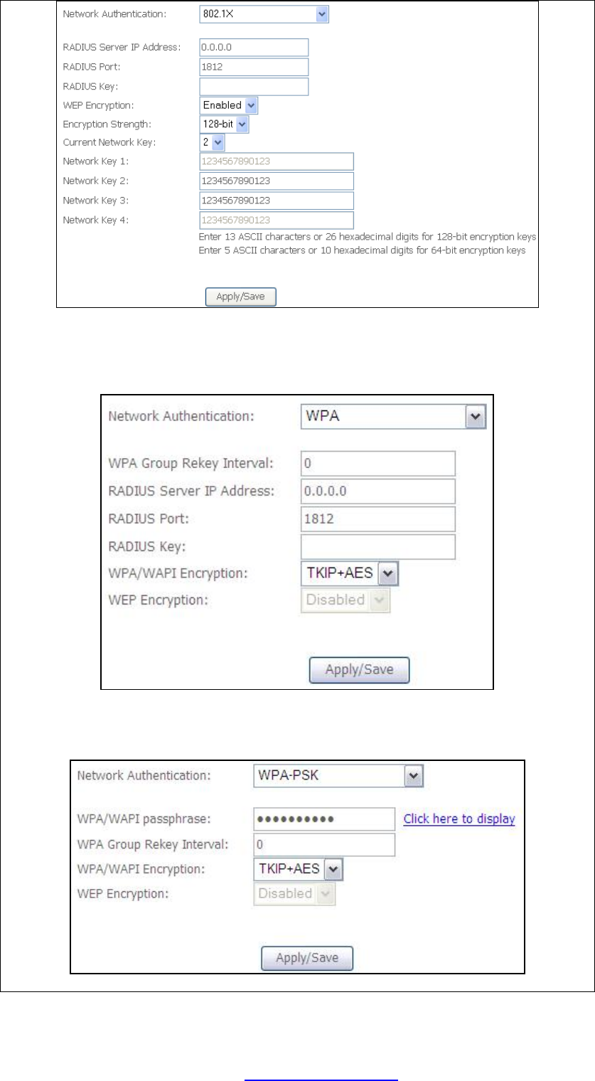
Each authentication type has its own settings. For example, selecting 802.1X
authentication will reveal the RADIUS Server IP address, Port and Key fields. WEP
Encryption will also be enabled as shown below.
PDF created with pdfFactory Pro trial version www.pdffactory.com
76
WEP Encryption
This option specifies whether data sent over the network is encrypted. The same
network key is used for data encryption and network authentication. Fo
ur network
keys can be defined although only one can be used at any one time. Use the Current
Network Key list box to select the appropriate network key.
Security options include authentication and encryption services based on the wired
equivalent privacy (WEP) algorithm. WEP is a set of security services used to
protect 802.11 networks from unauthorized access, such as eavesdropping; in this
case, the capture of wireless network traffic. When data encryption is enabled,
secret shared encryption keys ar
e generated and used by the source station and the
destination station to alter frame bits, thus avoiding disclosure to eavesdroppers.
Under shared key authentication, each wireless station is assumed to have received
a secret shared key over a secure channel that is independent from the 802.11
wireless network communications channel.
Encryption Strength
This drop-down list box will display when WEP Encryption is enabled. The key
strength is proportional to the number of binary bits comprising the key. This
means that keys with a greater number of bits have a greater degree of security and
are considerably more difficult to crack. Encryption strength can be set to either
64-bit or 128-bit. A 64-bit key is equivalent to 5 ASCII characters or 10
hexadecimal numbers. A 128-bit key contains 13 ASCII characters or 26
hexadecimal numbers. Each key contains a 24-bit header (an initiation vector)
which enables parallel decoding of multiple streams of encrypted data.
6.2.1 WPS
Wi-Fi Protected Setup (WPS) is an industry standard that simplifies wireless security
setup for certified network devices. Every WPS certified device has both a PIN
number and a push button, located on the device or accessed through device
software. The NEXUSLINK 3111u has both a WPS button on the device and a virtual
button accessible from the web user interface (WUI).
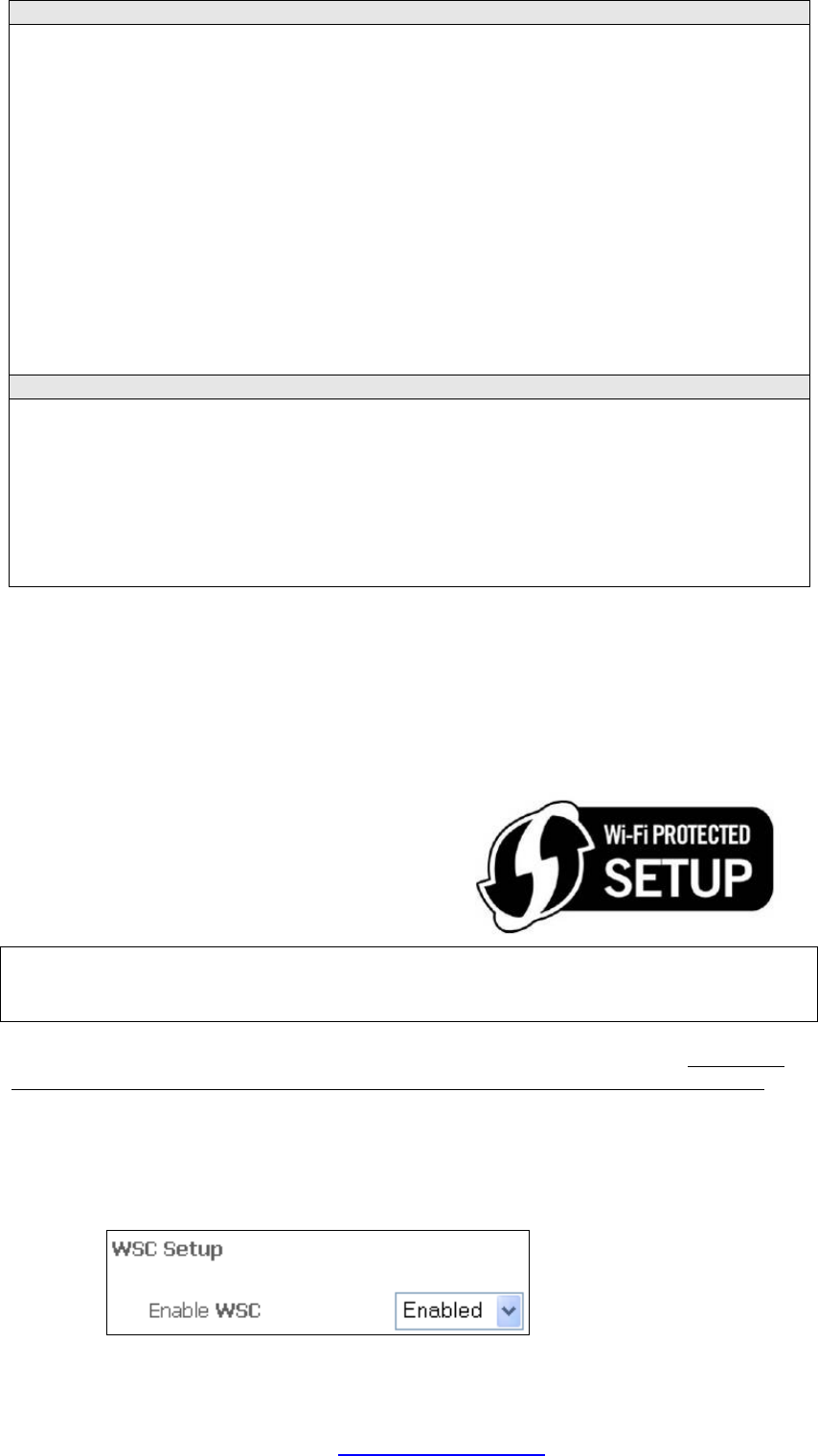
Devices with the WPS logo (shown here)
support WPS. If the WPS logo is not present
on your device it still may support WPS, in
this case, check the device documentation
for the phrase “Wi-Fi Protected Setup”.
NOTE: WPS is only available in Open, WPA-PSK, WPA2-PSK and Mixed
WPA2/WPA-PSK network authentication modes. Other authentication
modes do not use WPS so they must be configured manually.
To configure security settings with WPS, follow the procedures below. You must
choose either the Push-Button or PIN configuration method for Steps 6 and 7.
I. Setup
Step 1: Enable WPS by selecting Enabled from the drop down list box shown.
PDF created with pdfFactory Pro trial version www.pdffactory.com
77
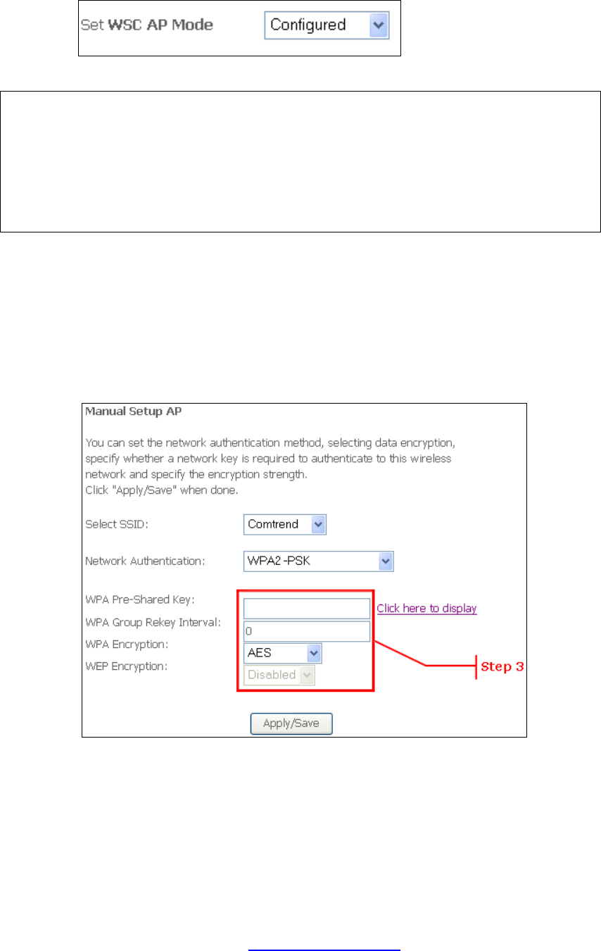
Step 2: Set the WSC AP Mode. Configured is used when the NEXUSLINK 3111u
will assign security settings to clients. Unconfigured is used when an
external client assigns security settings to the NEXUSLINK 3111u.
NOTES: Your client may or may not have the ability to provide security settings to
the NEXUSLINK 3111u. If it does not, then you must set the WSC AP
mode to Configured. Consult the device documentation to check its
capabilities.
In addition, using Windows Vista, you can add an external registrar using
the StartAddER button (Appendix E - WSC External Registrar has
detailed instructions).
II. NETWORK AUTHENTICATION
Step 3: Select Open, WPA-PSK, WPA2-PSK, or Mixed WPA2/WPA-PSK network
authentication mode from the Manual Setup AP section of the Wireless
Security screen. The example below shows WPA2-PSK mode.
Step 4: For the Pre-Shared Key (PSK) modes, enter a WPA Pre-Shared Key. You
will see the following dialog box if the Key is too short or too long.
PDF created with pdfFactory Pro trial version www.pdffactory.com
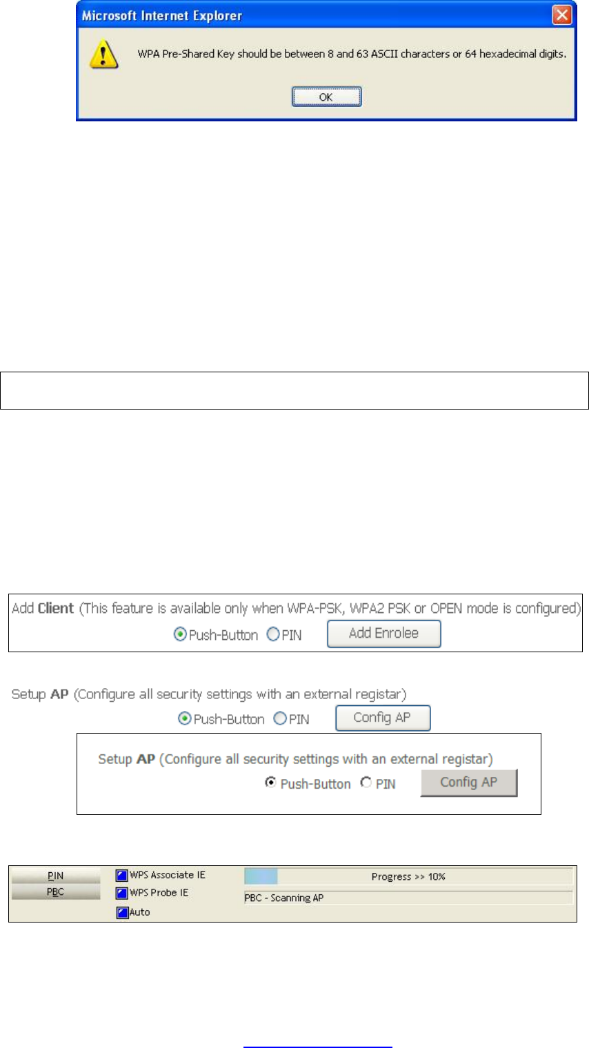
78
Step 5: Click the Save/Apply button at the bottom of the screen.
IIIa. PUSH-BUTTON CONFIGURATION
The WPS push-button configuration provides a semi-automated configuration
method. The WPS button on the rear panel of the router can be used for this
purpose or the Web User Interface (WUI) can be used exclusively.
The WPS push-button configuration is described in the procedure below. It is
assumed that the Wireless function is Enabled and that the router is configured as
the Wireless Access Point (AP) of your WLAN. In addition, the wireless client must
also be configured correctly and turned on, with WPS function enabled.
NOTE: The wireless AP on the router searches for 2 minutes. If the router stops
searching before you complete Step 7, return to Step 6.
Step 6: First method: WPS button
Press the WPS button on the rear panel of the router. The WPS LED will
blink to show that the router has begun searching for the client.
Second method: WUI virtual button
Select the Push-Button radio button in the WSC Setup section of the
Wireless Security screen, as shown in A or B below, and then click the
appropriate button based on the WSC AP mode selected in step 2.
A - For Configured mode, click the Add Enrollee button.
B - For Unconfigured mode, click the Config AP button.
Step 7: Go to your WPS wireless client and activate the push-button function.
A typical WPS client screenshot is shown below as an example.
Now go to Step 8 (part IV. Check Connection) to check the WPS connection.
PDF created with pdfFactory Pro trial version www.pdffactory.com
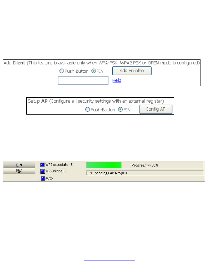
79
IIIb. WPS – PIN CONFIGURATION
Using this method, security settings are configured with a personal identification
number (PIN). The PIN can be found on the device itself or within the software.
The PIN may be generated randomly in the latter case. To obtain a PIN number for
your client, check the device documentation for specific instructions.
The WPS PIN configuration is described in the procedure below. It is assumed that
the Wireless function is Enabled and that the router is configured as the Wireless
Access Point (AP) of your wireless LAN. In addition, the wireless client must also be
configured correctly and turned on, with WPS function enabled.
NOTE: Unlike the push-button method, the pin method has no set time limit.
This means that the router will continue searching until it finds a client.
Step 6: Select the PIN radio button in the WSC Setup section of the Wireless
Security screen, as shown in A or B below, and then click the appropriate
button based on the WSC AP mode selected in step 2.
A - For Configured mode, enter the client PIN in the box provided and
then click the Add Enrollee button (see below).
B - For Unconfigured mode, click the Config AP button.
Step 7: Activate the PIN function on the wireless client. For Configured mode,
the client must be configured as an Enrollee. For Unconfigured mode,
the client must be configured as the Registrar. This is different from the
External Registrar function provided in Windows Vista.
The figure below provides an example of a WPS client PIN function in-progress.
Now go to Step 8 (part IV. Check Connection) to check the WPS connection.
IV. CHECK CONNECTION
Step 8: If the WPS setup method was successful, you will be able access the
wireless AP from the client. The client software should show the status.
PDF created with pdfFactory Pro trial version www.pdffactory.com

80
The example below shows that the connection established successfully.
You can also double-click the Wireless Network Connection icon from the
Network Connections window (or the system tray) to confirm the status of
the new connection.
PDF created with pdfFactory Pro trial version www.pdffactory.com