Comtrend NL-3111U A/VDSL Bonded Router User Manual UM NexusLink 3111u draft
Comtrend Corporation A/VDSL Bonded Router UM NexusLink 3111u draft
Comtrend >
Contents
- 1. 5.Users manual-1R1
- 2. 5.Users manual-2 R1
5.Users manual-2 R1
81
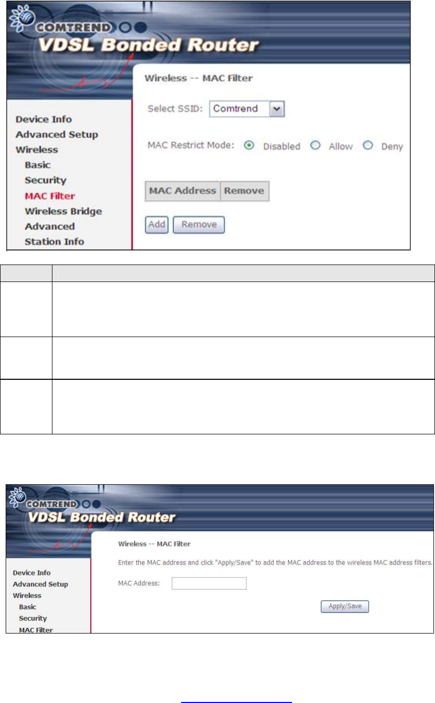
6.3 MAC Filter
This option allows access to the router to be restricted based upon MAC addresses.
To add a MAC Address filter, click the Add button shown below. To delete a filter,
select it from the MAC Address table below and click the Remove button.
Option
Description
Select
SSID Select the wireless network name from the drop-down box. SSID stands
for Service Set Identifier. All stations must be configured with the correct
SSID to access the WLAN. If the SSID does not match, that user will not
be granted access.
MAC
Restrict
Mode
Disabled: MAC filtering is disabled.
Allow: Permits access for the specified MAC addresses.
Deny: Rejects access for the specified MAC addresses.
MAC
Address
Lists the MAC addresses subject to the MAC Restrict Mode. A maximum
of 60 MAC addresses can be added. Every network device has a unique
48-bit MAC address. This is usually shown as xx.xx.xx.xx.xx.xx, where
xx are hexadecimal numbers.
After clicking the Add button, the following screen appears.
Input the MAC address in the box provided and click Save/Apply.
PDF created with pdfFactory Pro trial version www.pdffactory.com
82
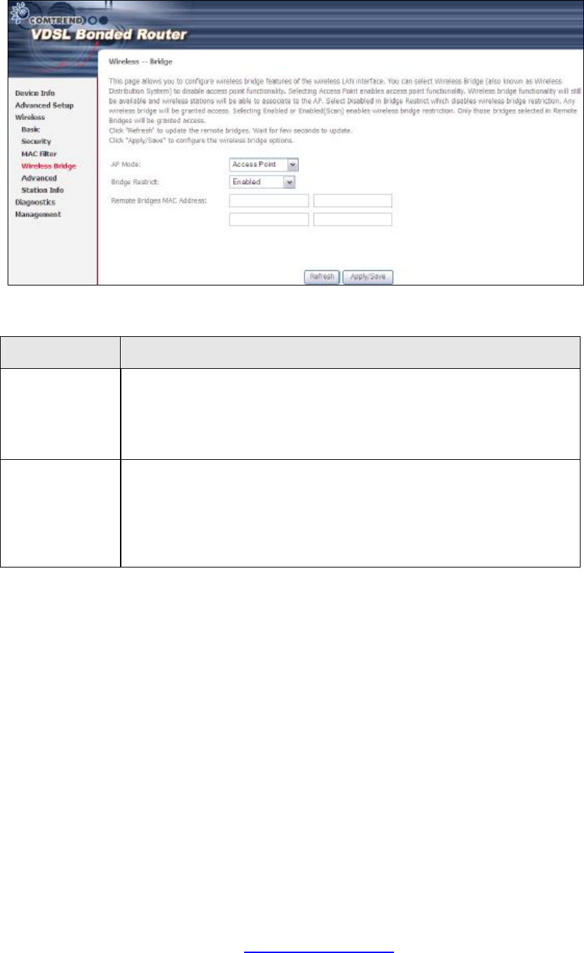
6.4 Wireless Bridge
This screen allows for the configuration of wireless bridge features of the WLAN
interface. See the table beneath for detailed explanations of the various options.
Click Save/Apply to implement new configuration settings.
Feature Description
AP Mode Selecting Wireless Bridge (aka Wireless Distribution System)
disables Access Point (AP) functionality, while selecting Access
Point enables AP functionality. In Access Point mode, wireless
bridge functionality will still be available and wireless stations
will be able to associate to the AP.
Bridge Restrict
Selecting Disabled disables wireless bridge restriction, which
means that any wireless bridge will be granted access.
Selecting Enabled or Enabled (Scan) enables wireless bridge
restriction. Only those bridges selected in the Remote Bridges
list will be granted access. Click Refresh to update the station
list when Bridge Restrict is enabled.
PDF created with pdfFactory Pro trial version www.pdffactory.com
83
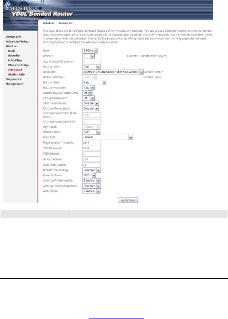
6.5 Advanced
The Advanced screen allows you to configure advanced features of the wireless LAN
interface. You can select a particular channel on which to operate, force the
transmission rate to a particular speed, set the fragmentation threshold, set the RTS
threshold, set the wakeup interval for clients in power-save mode, set the beacon
interval for the access point, set XPress mode and set whether short or long
preambles are used. Click Save/Apply to set new advanced wireless options.
Field Description
Band Set to 2.4 GHz for compatibility with IEEE 802.11x
standards. The new amendment allows IEEE 802.11n units
to fall back to slower speeds so that legacy IEEE 802.11x
devices can coexist in the same network. IEEE 802.11g
creates data-rate parity at 2.4 GHz with the IEEE 802.11a
standard, which has a 54 Mbps rate at 5 GHz. (IEEE 802.11a
has other differences compared to IEEE 802.11b or g, such
as offering more channels.)
Channel Drop-down menu that allows selection of a specific channel.
Auto Channel Timer (min)
Auto channel scan timer in minutes (0 to disable)
PDF created with pdfFactory Pro trial version www.pdffactory.com

84
Field Description
802.11n/EWC An equipment interoperability standard setting based on
IEEE 802.11n Draft 2.0 and Enhanced Wireless Consortium
(EWC)
Bandwidth Select 20GHz or 40GHz bandwidth. 40GHz bandwidth uses
two adjacent 20GHz bands for increased data throughput.
Control Sideband Select Upper or Lower sideband when in 40GHz mode.
802.11n Rate Set the physical transmission rate (PHY).
802.11n Protection Turn Off for maximized throughput.
Turn On for greater security.
RIFS Advertisement Reduced Interframe Space is the creation of a short time
delay between PDUs to improve wireless efficiency.
OBSS Co-Existence Co-existence between 20 MHZ AND 40 MHZ overlapping
Basic Service Set (OBSS) in WLAN.
RX Chain Power Save Enabling this feature turns off one of the Receive chains,
going from 2x2 to 2x1 to save power.
RX Chain Power Save
Quiet Time The number of seconds the traffic must be below the PPS
value below before the Rx Chain Power Save feature
activates itself.
RX Chain Power Save PPS
The maximum number of packets per seconds that can be
processed by the WLAN interface for a duration of Quiet
Time, described above, before the Rx Chain Power Save
feature activates itself.
Support 802.11n Client
Only Turn Off to allow 802.11b/g clients access to the router.
Turn On to prohibit 802.11b/g clients access to the router.
54g Rate Drop-down menu that specifies the following fixed rates:
Auto: Default. Uses the 11 Mbps data rate when possible
but drops to lower rates when necessary. 1 Mbps, 2Mbps,
5.5Mbps, or 11Mbps fixed rates. The appropriate setting is
dependent on signal strength.
Multicast Rate Setting for multicast packet transmit rate (1-54 Mbps)
Basic Rate Setting for basic transmission rate.
Fragmentation Threshold
A threshold, specified in bytes, that determines whether
packets will be fragmented and at what size. On an 802.11
WLAN, packets that exceed the fragmentation threshold are
fragmented, i.e., split into, smaller units suitable for the
circuit size. Packets smaller than the specified
fragmentation threshold value are not fragmented. Enter a
value between 256 and 2346. If you experience a high
packet error rate, try to slightly increase your
Fragmentation Threshold. The value should remain at its
default setting of 2346. Setting the Fragmentation
Threshold too low may result in poor performance.
RTS Threshold Request to Send, when set in bytes, specifies the packet size
beyond which the WLAN Card invokes its RTS/CTS
mechanism. Packets that exceed the specified RTS
threshold trigger the RTS/CTS mechanism. The NIC
transmits smaller packet without using RTS/CTS. The
default setting of 2347 (maximum length) disables RTS
Threshold.
PDF created with pdfFactory Pro trial version www.pdffactory.com

85
Field Description
DTIM Interval Delivery Traffic Indication Message (DTIM) is also known as
Beacon Rate. The entry range is a value between 1 and
65535. A DTIM is a countdown variable that informs clients
of the next window for listening to broadcast and multicast
messages. When the AP has buffered broadcast or
multicast messages for associated clients, it sends the next
DTIM with a DTIM Interval value. AP Clients hear the
beacons and awaken to receive the broadcast and multicast
messages. The default is 1.
Beacon Interval The amount of time between beacon transmissions in
milliseconds. The default is 100 ms and the acceptable
range is 1 – 65535. The beacon transmissions identify the
presence of an access point. By default, network devices
passively scan all RF channels listening for beacons coming
from access points. Before a station enters power save
mode, the station needs the beacon interval to know when
to wake up to receive the beacon (and learn whether there
are buffered frames at the access point).
Global Max Clients The maximum number of clients that can connect to the
router.
Xpress TM Technology Xpress Technology is compliant with draft specifications of
two planned wireless industry standards.
Transmit Power Set the power output (by percentage) as desired.
WMM (Wi-Fi Multimedia) The technology maintains the priority of audio, video and
voice applications in a Wi-Fi network. It allows multimedia
service get higher priority.
WMM No
Acknowledgement Refers to the acknowledge policy used at the MAC level.
Enabling no Acknowledgement can result in more efficient
throughput but higher error rates in a noisy Radio Frequency
(RF) environment.
WMM APSD This is Automatic Power Save Delivery. It saves power.
PDF created with pdfFactory Pro trial version www.pdffactory.com
86
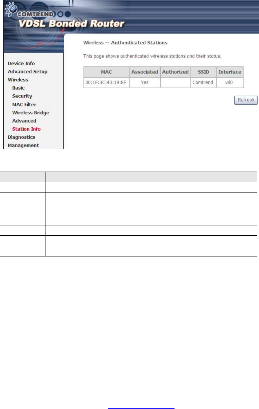
6.6 Station Info
This page shows authenticated wireless stations and their status. Click the Refresh
button to update the list of stations in the WLAN.
Consult the table below for descriptions of each column heading.
Heading Description
MAC Lists the MAC address of all the stations.
Associated Lists all the stations that are associated with the Access
Point, along with the amount of time since packets were transferred
to and from each station. If a station is idle for too long, it is
removed from this list.
Authorized Lists those devices with authorized access.
SSID Lists which SSID of the modem that the stations connect to.
Interface Lists which interface of the modem that the stations connect to.
PDF created with pdfFactory Pro trial version www.pdffactory.com
87
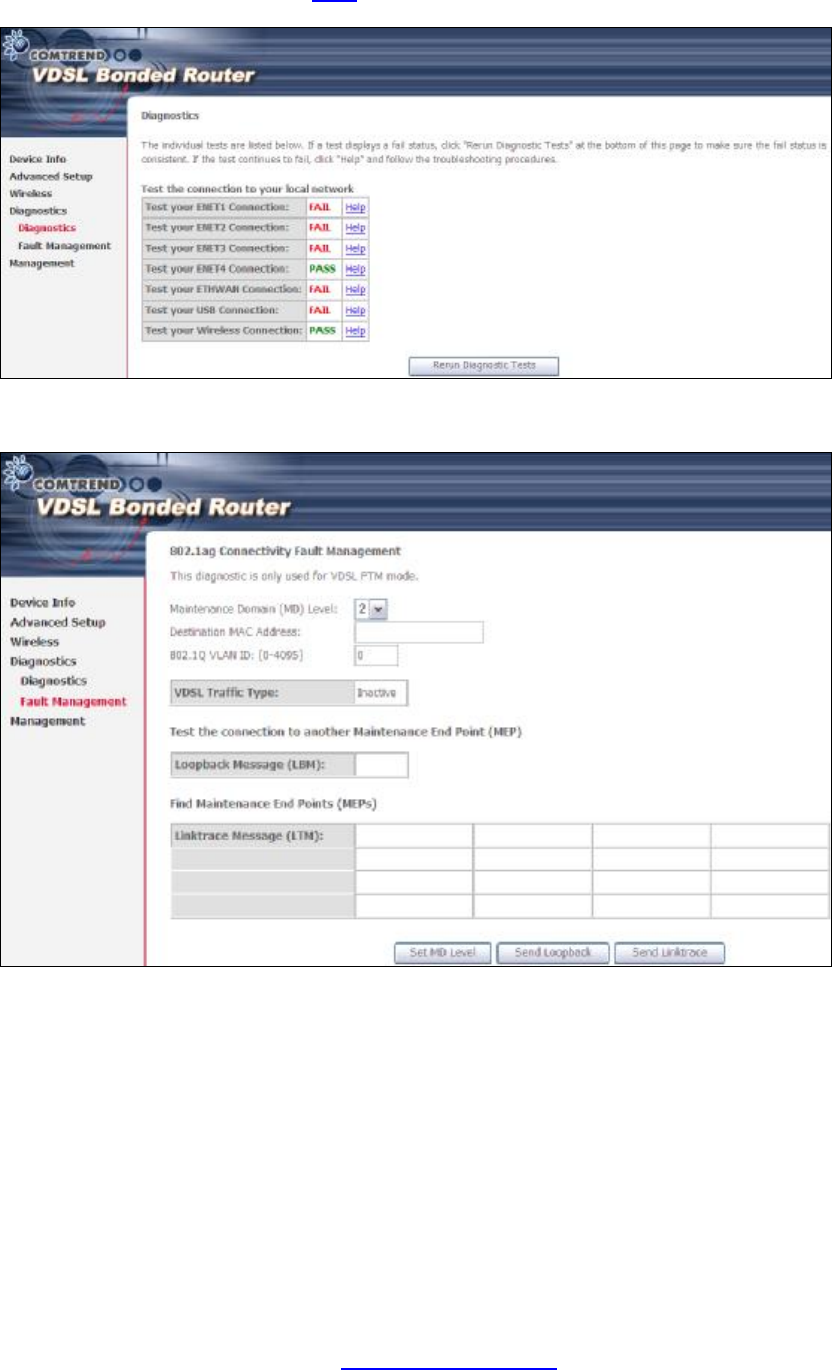
Chapter 7 Diagnostics
The first Diagnostics screen is a dashboard that shows overall connection status.
If a test displays a fail status, click the button to retest and confirm the error.
If a test continues to fail, click Help and follow the troubleshooting procedures.
The second Diagnostics screen (Fault Management) is used for VDSL diagnostics.
PDF created with pdfFactory Pro trial version www.pdffactory.com
88
Chapter 8 Management
8.1 Settings
This includes 8.1.1 Backup Settings, 8.1.2 Update Settings, and 8.1.3 Restore
Default screens.
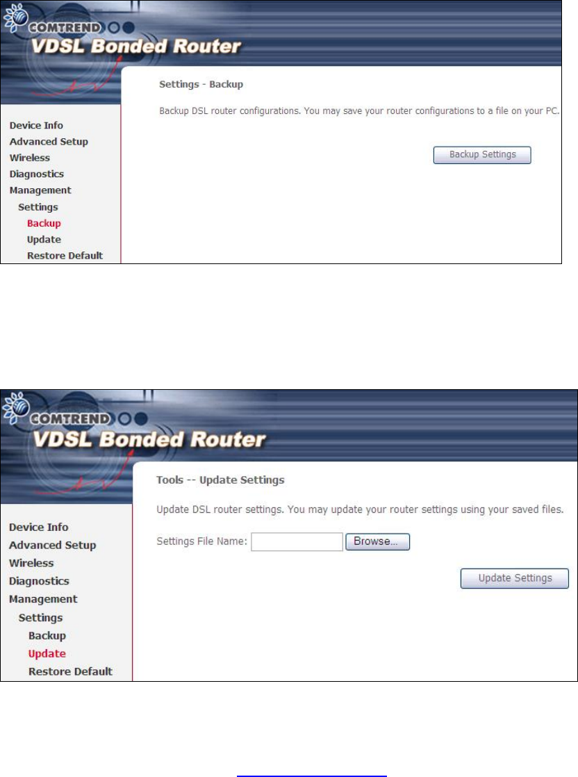
8.1.1 Backup Settings
To save the current configuration to a file on your PC, click Backup Settings. You
will be prompted for backup file location. This file can later be used to recover
settings on the Update Settings screen, as described below.
8.1.2 Update Settings
This option recovers configuration files previously saved using Backup Settings.
Enter the file name (including folder path) in the Settings File Name box, or press
Browse… to search for the file, then click Update Settings to recover settings.
PDF created with pdfFactory Pro trial version www.pdffactory.com
89
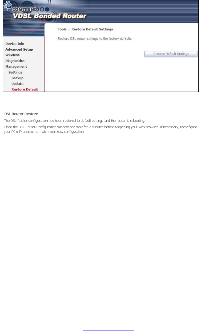
8.1.3 Restore Default
Click Restore Default Settings to restore factory default settings.
After Restore Default Settings is clicked, the following screen appears.
Close the browser and wait for 2 minutes before reopening it. It may also be
necessary, to reconfigure your PC IP configuration to match any new settings.
NOTE: This entry has the same effect as the Reset button. The NEXUSLINK
3111u board hardware and the boot loader support the reset to default. If
the Reset button is continuously pressed for more than 5 seconds, the
boot loader will erase the configuration data saved in flash memory.
PDF created with pdfFactory Pro trial version www.pdffactory.com
90
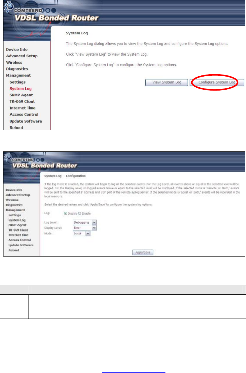
8.2 System Log
This function allows a system log to be kept and viewed upon request.
Follow the steps below to configure, enable, and view the system log.
STEP 1: Click Configure System Log, as shown below (circled in Red).
STEP 2: Select desired options and click Apply/Save.
Consult the table below for detailed descriptions of each system log option.
Option
Description
Log Indicates whether the system is currently recording events. The user
can enable or disable event logging. By default, it is disabled. To
enable it, select the Enable radio button and then click Apply/Save.
PDF created with pdfFactory Pro trial version www.pdffactory.com
91
Option
Description
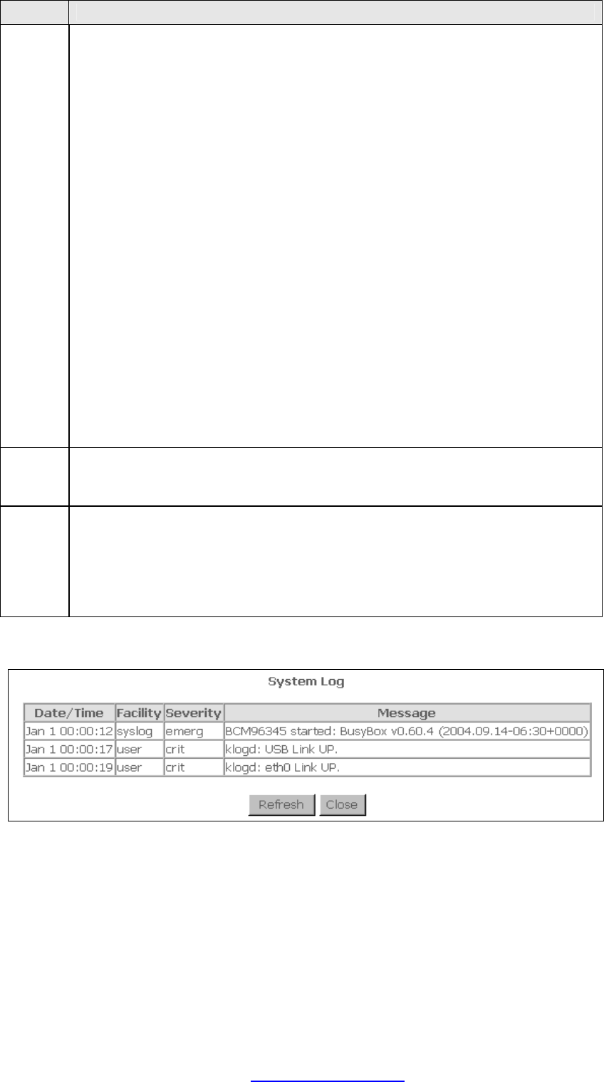
Log
Level Allows you to configure the event level and filter out unwanted events
below this level. The events ranging from the highest critical level
“Emergency” down to this configured level will be recorded to the log
buffer on the NEXUSLINK 3111u SDRAM. When the log buffer is full, the
newer event will wrap up to the top of the log buffer and overwrite the old
event. By default, the log level is “Debugging”, which is the lowest critical
level.
The log levels are defined as follows:
• Emergency = system is unusable
• Alert = action must be taken immediately
• Critical = critical conditions
• Error = Error conditions
• Warning = normal but significant condition
• Notice= normal but insignificant condition
• Informational= provides information for reference
• Debugging = debug-level messages
Emergency is the most serious event level, whereas Debugging is the
least important. For instance, if the log level is set to Debugging, all the
events from the lowest Debugging level to the most critical level
Emergency level will be recorded. If the log level is set to Error, only
Error and the level above will be logged.
Display
Level Allows the user to select the logged events and displays on the View
System Log window for events of this level and above to the highest
Emergency level.
Mode Allows you to specify whether events should be stored in the local
memory, or be sent to a remote system log server, or both
simultaneously. If remote mode is selected, view system log will not be
able to display events saved in the remote system log server.
When either Remote mode or Both mode is configured, the WEB UI will
prompt the user to enter the Server IP address and Server UDP port.
STEP 3: Click View System Log. The results are displayed as follows.
PDF created with pdfFactory Pro trial version www.pdffactory.com

92
8.3 SNMP Agent
Simple Network Management Protocol (SNMP) allows a management application to
retrieve statistics and status from the SNMP agent in this device. Select the
Enable radio button, configure options, and click Save/Apply to activate SNMP.
PDF created with pdfFactory Pro trial version www.pdffactory.com
93
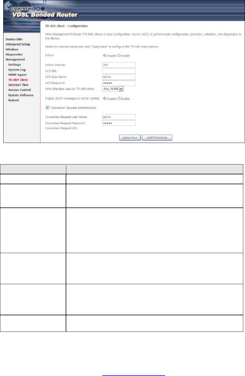
8.4 TR-069 Client
WAN Management Protocol (TR-069) allows an Auto-Configuration Server (ACS) to
perform auto-configuration, provision, collection, and diagnostics to this device.
Select desired values and click Apply/Save to configure TR-069 client options.
The table below is provided for ease of reference.
Option Description
Inform Disable/Enable TR-069 client on the CPE.
Inform Interval The duration in seconds of the interval for which the CPE
MUST attempt to connect with the ACS and call the Inform
method.
ACS URL URL for the CPE to connect to the ACS using the CPE WAN
Management Protocol. This parameter MUST be in the form
of a valid HTTP or HTTPS URL. An HTTPS URL indicates that
the ACS supports SSL. The “host” portion of this URL is
used by the CPE for validating the certificate from the ACS
when using certificate-based authentication.
ACS User Name Username used to authenticate the CPE when making a
connection to the ACS using the CPE WAN Management
Protocol. This username is used only for HTTP-based
authentication of the CPE.
ACS Password Password used to authenticate the CPE when making a
connection to the ACS using the CPE WAN Management
Protocol. This password is used only for HTTP-based
authentication of the CPE.
WAN Interface used
by TR-069 client Choose Any_WAN, LAN, Loopback or a configured
connection.
PDF created with pdfFactory Pro trial version www.pdffactory.com
94
Option Description
Display SOAP
messages on serial
console
Enable/Disable SOAP messages on serial console. This
option is used for advanced troubleshooting of the device.
Connection Request
Authorization Tick the checkbox þ to enable.
User Name Username used to authenticate an ACS making a
Connection Request to the CPE.
Password Password used to authenticate an ACS making a
Connection Request to the CPE.
URL IP address and port the ACS uses to connect to NEXUSLINK
3111u.
The Get RPC Methods button forces the CPE to establish an immediate connection
to the ACS. This may be used to discover the set of methods supported by the ACS
or CPE. This list may include both standard TR-069 methods (those defined in this
specification or a subsequent version) and vendor-specific methods. The receiver of
the response MUST ignore any unrecognized methods.
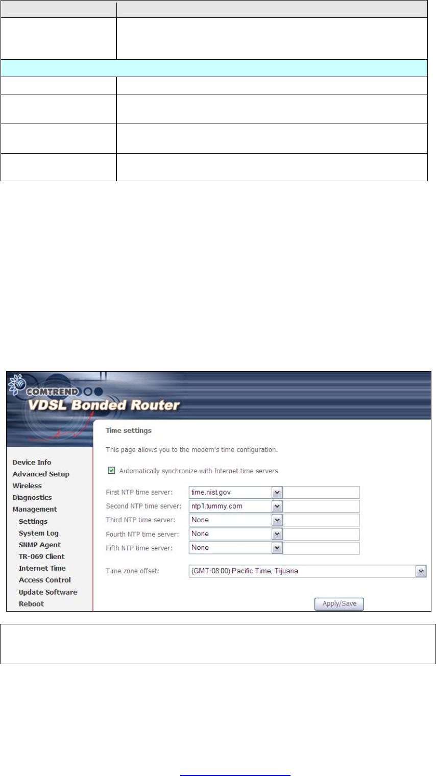
8.5 Internet Time
This option automatically synchronizes the router time with Internet timeservers.
To enable time synchronization, tick the corresponding checkbox þ, choose your
preferred time server(s), select the correct time zone offset, and click Save/Apply.
NOTE: Internet Time must be activated to use Parental Control.
In addition, this menu item is not displayed when in Bridge mode since
the router would not be able to connect to the NTP timeserver.
PDF created with pdfFactory Pro trial version www.pdffactory.com
95
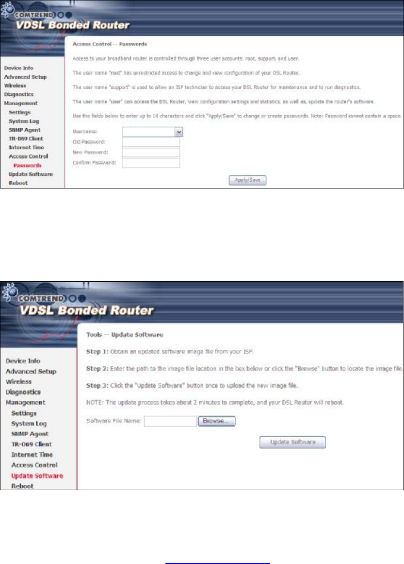
8.6 Access Control
8.6.1 Passwords
This screen is used to configure the user account access passwords for the device.
Access to the NEXUSLINK 3111u is controlled through the following three user
accounts:
• root - unrestricted access to change and view the configuration.
• support - used for remote maintenance and diagnostics of the router
• user - can view configuration settings & statistics and update firmware.
Use the fields below to change password settings. Click Save/Apply to continue.
NOTE: Passwords can be up to 16 characters in length.
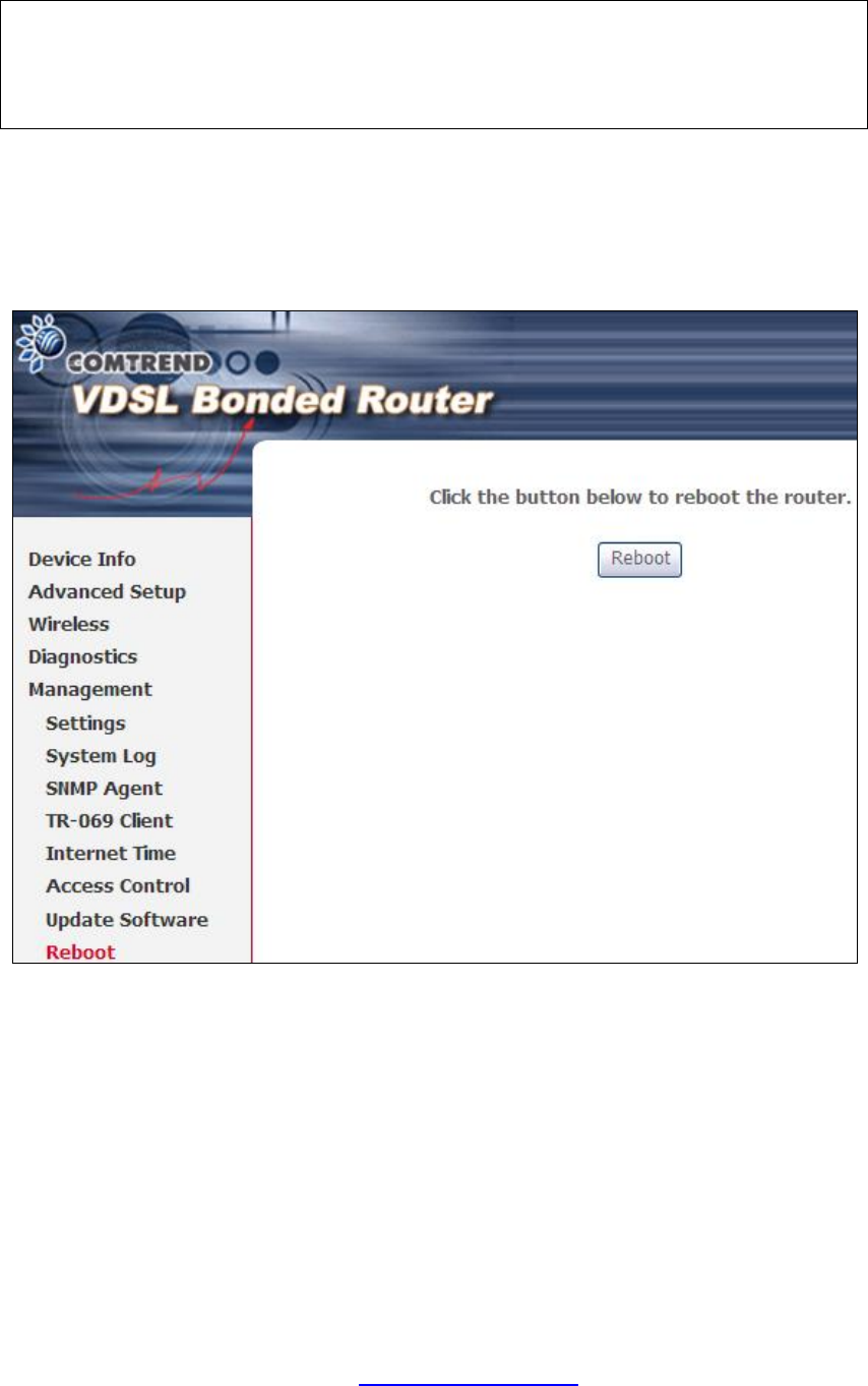
8.7 Update Software
This option allows for firmware upgrades from a locally stored file.
PDF created with pdfFactory Pro trial version www.pdffactory.com
96
STEP 1: Obtain an updated software image file from your ISP.
STEP 2: Enter the path and filename of the firmware image file in the Software
File Name field or click the Browse button to locate the image file.
STEP 3: Click the Update Software button once to upload and install the file.
NOTE: The update process will take about 2 minutes to complete. The device
will reboot and the browser window will refresh to the default screen upon
successful installation. It is recommended that you compare the
Software Version on the Chapter 4 Device Information screen with the
firmware version installed, to confirm the installation was successful.
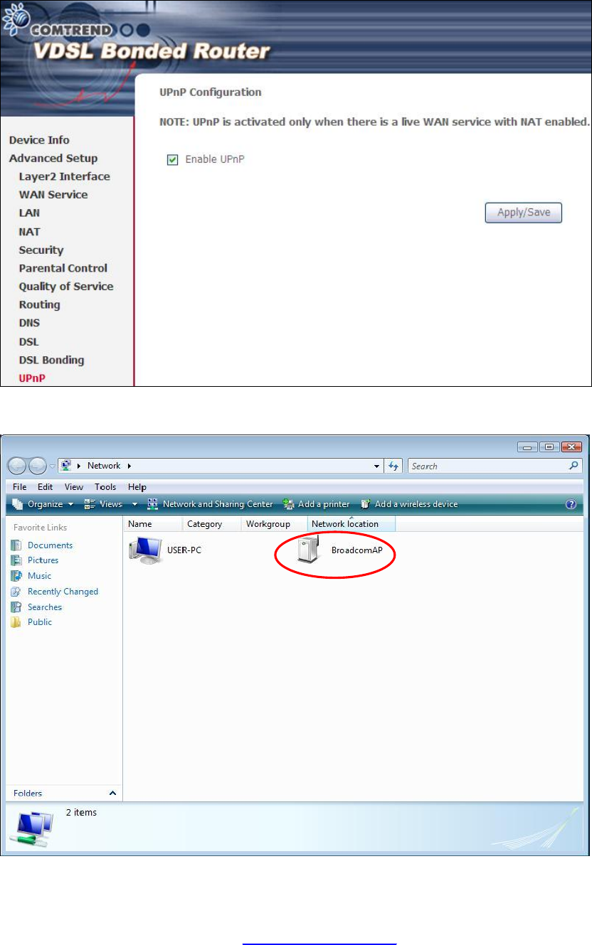
8.8 Reboot
To save the current configuration and reboot the router, click Save/Reboot.
NOTE: You may need to close the browser window and wait for 2 minutes before
reopening it. It may also be necessary, to reset your PC IP configuration.
PDF created with pdfFactory Pro trial version www.pdffactory.com

97
Appendix A - Firewall
STATEFUL PACKET INSPECTION
Refers to an architecture, where the firewall keeps track of packets on each
connection traversing all its interfaces and makes sure they are valid. This is in
contrast to static packet filtering which only examines a packet based on the
information in the packet header.
DENIAL OF SERVICE ATTACK
Is an incident in which a user or organization is deprived of the services of a
resource they would normally expect to have. Various DoS attacks the device can
withstand are ARP Attack, Ping Attack, Ping of Death, Land, SYN Attack, Smurf
Attack, and Tear Drop.
TCP/IP/PORT/INTERFACE FILTER
These rules help in the filtering of traffic at the Network layer (i.e. Layer 3).
When a Routing interface is created, Enable Firewall must be checked.
Navigate to Advanced Setup à Security à IP Filtering.
OUTGOING IP FILTER
Helps in setting rules to DROP packets from the LAN interface. By default, if the
Firewall is Enabled, all IP traffic from the LAN is allowed. By setting up one or more
filters, specific packet types coming from the LAN can be dropped.
Example 1: Filter Name : Out_Filter1
Protocol : TCP
Source IP address : 192.168.1.45
Source Subnet Mask : 255.255.255.0
Source Port : 80
Dest. IP Address : NA
Dest. Subnet Mask : NA
Dest. Port : NA
This filter will Drop all TCP packets coming from the LAN with IP
Address/Subnet Mask of 192.168.1.45/24 having a source port of 80
irrespective of the destination. All other packets will be Accepted.
Example 2: Filter Name : Out_Filter2
Protocol : UDP
Source IP Address : 192.168.1.45
Source Subnet Mask : 255.255.255.0
Source Port : 5060:6060
Dest. IP Address : 172.16.13.4
Dest. Subnet Mask : 255.255.255.0
Dest. Port : 6060:7070
This filter will drop all UDP packets coming from the LAN with IP Address /
Subnet Mask of 192.168.1.45/24 and a source port range of 5060 to 6060,
destined to 172.16.13.4/24 and a destination port range of 6060 to 7070.
INCOMING IP FILTER
Helps in setting rules to Allow or Deny packets from the WAN interface. By default,
all incoming IP traffic from the WAN is Blocked, if the Firewall is Enabled. By setting
up one or more filters, specific packet types coming from the WAN can be Accepted.
PDF created with pdfFactory Pro trial version www.pdffactory.com

98
Example 1: Filter Name : In_Filter1
Protocol : TCP
Policy : Allow
Source IP Address : 210.168.219.45
Source Subnet Mask : 255.255.0.0
Source Port : 80
Dest. IP Address : NA
Dest. Subnet Mask : NA
Dest. Port : NA
Selected WAN interface : br0
This filter will ACCEPT all TCP packets coming from WAN interface “br0” with IP
Address/Subnet Mask 210.168.219.45/16 with a source port of 80, irrespective
of the destination. All other incoming packets on this interface are DROPPED.
Example 2: Filter Name : In_Filter2
Protocol : UDP
Policy : Allow
Source IP Address : 210.168.219.45
Source Subnet Mask : 255.255.0.0
Source Port : 5060:6060
Dest. IP Address : 192.168.1.45
Dest. Sub. Mask : 255.255.255.0
Dest. Port : 6060:7070
Selected WAN interface : br0
This rule will ACCEPT all UDP packets coming from WAN interface “br0” with IP
Address/Subnet Mask 210.168.219.45/16 and a source port in the range of
5060 to 6060, destined to 192.168.1.45/24 and a destination port in the range
of 6060 to 7070. All other incoming packets on this interface are DROPPED.
MAC LAYER FILTER
These rules help in the filtering of Layer 2 traffic. MAC Filtering is only effective in
Bridge mode. After a Bridge mode connection is created, navigate to Advanced
Setup à Security à MAC Filtering in the WUI.
Example 1: Global Policy : Forwarded
Protocol Type : PPPoE
Dest. MAC Address : 00:12:34:56:78:90
Source MAC Address : NA
Src. Interface : eth1
Dest. Interface : eth2
Addition of this rule drops all PPPoE frames going from eth1 to eth2 with a
Destination MAC Address of 00:12:34:56:78:90 irrespective of its Source MAC
Address. All other frames on this interface are forwarded.
Example 2: Global Policy : Blocked
Protocol Type : PPPoE
Dest. MAC Address : 00:12:34:56:78:90
Source MAC Address : 00:34:12:78:90:56
Src. Interface : eth1
Dest. Interface : eth2
Addition of this rule forwards all PPPoE frames going from eth1 to eth2 with a
Destination MAC Address of 00:12:34:56:78 and Source MAC Address of
00:34:12:78:90:56. All other frames on this interface are dropped.
PDF created with pdfFactory Pro trial version www.pdffactory.com

99
DAYTIME PARENTAL CONTROL
This feature restricts access of a selected LAN device to an outside Network through
the NEXUSLINK 3111u, as per chosen days of the week and the chosen times.
Example: User Name : FilterJohn
Browser's MAC Address : 00:25:46:78:63:21
Days of the Week : Mon, Wed, Fri
Start Blocking Time : 14:00
End Blocking Time : 18:00
With this rule, a LAN device with MAC Address of 00:25:46:78:63:21 will have
no access to the WAN on Mondays, Wednesdays, and Fridays, from 2pm to 6pm.
On all other days and times, this device will have access to the outside
Network.
PDF created with pdfFactory Pro trial version www.pdffactory.com

100
Appendix B - Pin Assignments
ETHERNET Ports (RJ45)
ETHERNET LAN Ports (10/100Base-T)
Pin Signal name Signal definition
1 TXP Transmit data (positive lead)
2 TXN Transmit data (negative lead)
3 RXP Receive data (positive lead)
4 NC Not used
5 NC Not used
6 RXN Receive data (negative lead)
7 NC Not used
8 NC Not used
Table 1
Signals for ETHERNET WAN port (10/1001000Base-T)
Pin Signal name Signal definition
1 TRD+(0) Transmit/Receive data 0 (positive lead)
2 TRD-(0) Transmit/Receive data 0 (negative lead)
3 TRD+(1) Transmit/Receive data 1 (positive lead)
4 TRD+(2) Transmit/Receive data 2 (positive lead)
5 TRD-(2) Transmit/Receive data 2 (negative lead)
6 TRD-(1) Transmit/Receive data 1 (negative lead)
7 TRD+(3) Transmit/Receive data 3 (positive lead)
8 TRD-(3) Transmit/Receive data 3 (negative lead)
Table 2
PDF created with pdfFactory Pro trial version www.pdffactory.com

101
Appendix C - Specifications
Hardware Interface
l RJ-14 X1 for VDSL Bonded,
l RJ-45 X 4 for LAN, (10/100 BaseT auto-sense)
l RJ-45 X 1 for Flex Port, (10/100/1000 BaseT auto-sense)
l Reset Button X 1,
l Power switch X 1,
l USB host X 1
Dual WAN Interface
VDSL WAN
l Comply with G.993.2 (supporting profile 8a, 8b, 8c, 8d, 12a, 12b)
l MULTI-DSL bonded : up to 12a profile
GbE WAN
l 10/100/1000 Mbps
l RJ45 connector
LAN Interface
l Standard IEEE 802.3, IEEE 802.3u
l MDI/MDX support Yes
l Multiple Subnets on LAN
Wireless Interface
l IEEE802.11b/g/n
l 64, 128-bit Wired Equivalent Privacy (WEP) Data Encryption
l 11 Channels (US, Canada)/ 13 Channels (Europe)/ 14 Channels (Japan)
l Up to 300Mbps data rate
l Multiple BSSID
l MAC address filtering, WDS, WEP, WPA, WPA2, IEEE 802.1x
l 10,25,50,100mW@22MHz channel bandwidth output power level can be
selected according to the environment
ATM Attributes
l RFC 2684 (RFC 1483) Bridge/Route;
l RFC 2516 (PPPoE); RFC 2364 (PPPoA); RFC 1577 (IPoA)
l Support up to 8 PVCs
l AAL type AAL5
l ATM service class UBR/CBR/VBR-rt/VBR-nrt
l ATM UNI support UNI 3.1/4.0
l OAM F4/F5
PTM Attributes
l ATM Adaptation Layer: Ethernet packet format
l Support 8 flows
l Support preemption and dual latency
l Support IEEE 802.1ag Ethernet CFM (Connectivity Fault Management)
l Support PTM shaping Latency.................Yes
PDF created with pdfFactory Pro trial version www.pdffactory.com

102
Management
l Compliant with TR-069/TR-098/TR-104/TR-111 remote management protocols,
SNMP, Telnet, Web-based management, Configuration backup and restoration,
l Software upgrade via HTTP / TFTP / FTP server
Networking Protocols
l RFC2684 VC-MUX, LLC/SNAP encapsulations for bridged or routed packet
l RFC2364 PPP over AAL5
l IPoA, PPPoA, PPPoE, Multiple PPPoE sessions on single PVC, PPPoE
pass-through
l PPPoE filtering of on-PPPoE packets between WAN and LAN
l Transparent bridging between all LAN and WAN interfaces
l 802.1p/802.1q VLAN support
l Spanning Tree Algorithm
l IGMP Proxy V1/V2/V3, IGMP Snooping V1/V2/V3, Fast leave
l Static route, RIP v1/v2, ARP, RARP, SNTP, DHCP Server/Client/Relay,
l DNS Relay, Dynamic DNS,
l IPv6 subset
Security Functions
l PAP, CHAP, Packet and MAC address filtering, SSH,
l VPN termination
l Three level login: local admin, local user and remote technical support access
QoS
l Packet level QoS classification rules,
l Priority queuing using ATM TX queues,
l IP TOS/Precedence,
l 802.1p marking,
l DiffServ DSCP marking
l Src/dest MAC addresses classification
Firewall/Filtering
l Stateful Inspection Firewall
l Stateless Packet Filter
l Day-time Parental Control
l URI/URL filtering
l Denial of Service (DOS): ARP attacks, Ping attacks, Ping of Death, LAND,SYNC,
Smurf, Unreachable, Teardrop
l TCP/IP/Port/interface filtering rules Support both incoming and outgoing
filtering
NAT/NAPT
l Support Port Triggering and Port forwarding
l Symmetric port-overloading NAT, Full-Cone NAT
l Dynamic NAPT (NAPT N-to-1)
l Support DMZ host
l Virtual Server
l VPN Passthrough (PPTP, L2TP, IPSec)
PDF created with pdfFactory Pro trial version www.pdffactory.com

103
Application Layer Gateway (ALG)
SIP, H.323, Yahoo messenger, ICQ, RealPlayer, Net2Phone, NetMeeting, MSN, X-box,
Microsoft DirectX games and etc.
Power Supply ................................................Input: 100 - 240 Vac
Output: 12 Vdc / 1.5 A
Environment Condition
Operating temperature...........................0 ~ 40 degrees Celsius
Relative humidity...................................5 ~ 95% (non-condensing)
Dimensions .....................................205 mm (W) x 48 mm (H) x 145 mm (D)
Certifications................................... FCC Part 15, FCC Part 68
Kit Weight
(1*NEXUSLINK 3111u, 1*RJ14 cable, 1*RJ45 cable, 1*power adapter, 1*CD-ROM)
= 1.0 kg
NOTE: Specifications are subject to change without notice
PDF created with pdfFactory Pro trial version www.pdffactory.com

104
Appendix D - SSH Client
Unlike Microsoft Windows, Linux OS has a ssh client included. For Windows users,
there is a public domain one called “putty” that can be downloaded from here:
http://www.chiark.greenend.org.uk/~sgtatham/putty/download.html
To access the ssh client you must first enable SSH access for the LAN or WAN from
the Management à Access Control à Services menu in the web user interface.
To access the router using the Linux ssh client
For LAN access, type: ssh -l root 192.168.1.1
For WAN access, type: ssh -l support WAN IP address
To access the router using the Windows “putty” ssh client
For LAN access, type: putty -ssh -l root 192.168.1.1
For WAN access, type: putty -ssh -l support WAN IP address
NOTE: The WAN IP address can be found on the Device Info à WAN screen
PDF created with pdfFactory Pro trial version www.pdffactory.com
105
Appendix E - WSC External Registrar
Follow these steps to add an external registrar using the web user interface (WUI)
on a personal computer running the Windows Vista operating system:
Step 1: Enable UPnP on the Advanced Setup.
Step 2: Open the Network folder and look for the BroadcomAP icon.
PDF created with pdfFactory Pro trial version www.pdffactory.com
106
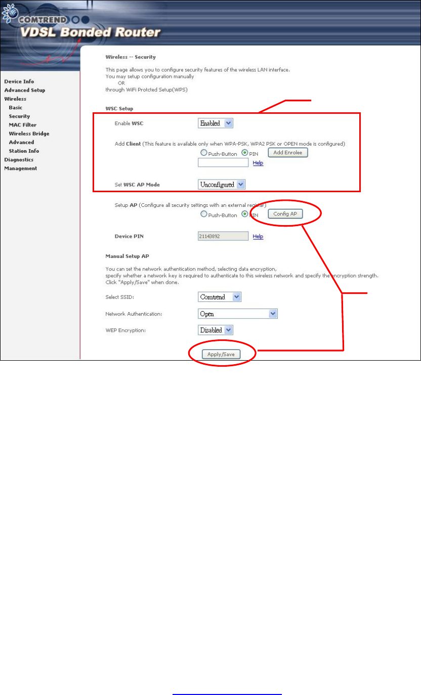
Step 3: On the Wireless à Security screen, enable WSC by selecting Enabled
from the drop down list box and set the WSC AP Mode to Unconfigured.
Step 4: Click the Save/Apply button at the bottom of the screen. The screen
will go blank while the router applies the new Wireless settings. When the screen
returns, press the Config AP button, as shown above.
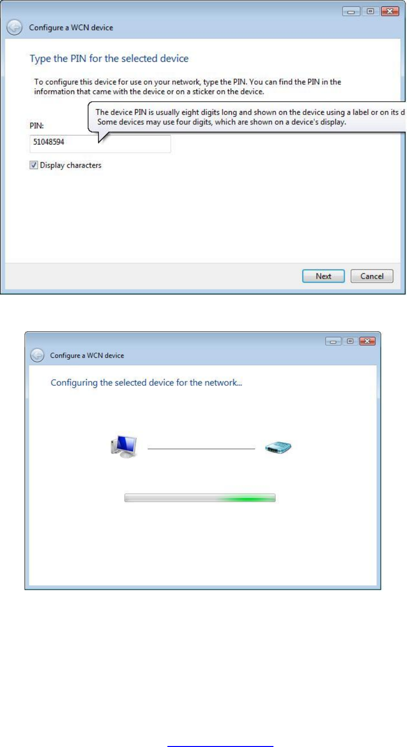
Step 5: Now return to the Network folder and click the BroadcomAP icon. A
dialog box will appear asking for the Device PIN number. Enter the
Device PIN as shown on the Wireless à Security screen. Click Next.
Step 3
Step 4
PDF created with pdfFactory Pro trial version www.pdffactory.com
108
Appendix F - Printer Server
These steps explain the procedure for enabling the Printer Server.
NOTE: This function only applies to models with an USB host port.
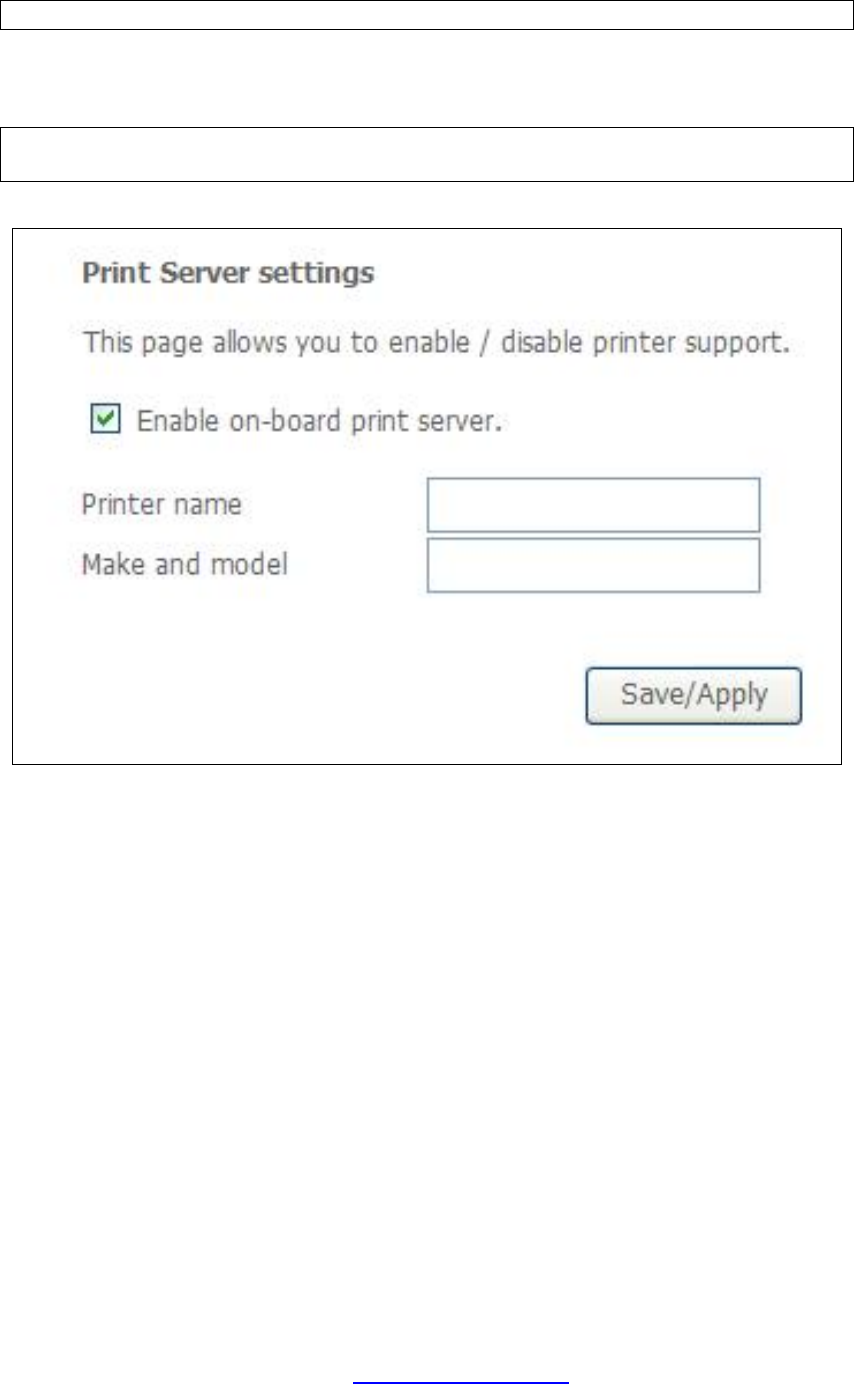
STEP 1: Enable Print Server from Web User Interface. Select Enable on-board
print server checkbox þ and enter Printer name and Make and model
NOTE: The Printer name can be any text string up to 40 characters.
The Make and model can be any text string up to 128 characters.
PDF created with pdfFactory Pro trial version www.pdffactory.com
110
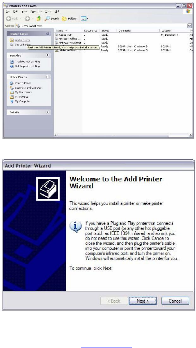
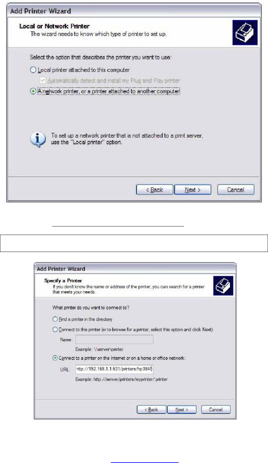
STEP 4: Select Network Printer and click Next.
STEP 5: Select Connect to a printer on the Internet and enter your printer link.
(e.g. http://192.168.1.1:631/printers/hp3845) and click Next.
NOTE: The printer name must be the same name entered in the VDSL modem
WEB UI “printer server setting” as in step 1.
PDF created with pdfFactory Pro trial version www.pdffactory.com
114
Appendix G - Connection Setup
Creating a WAN connection is a two-stage process.
1 - Setup a Layer 2 Interface (ATM, PTM or Ethernet).
2 - Add a WAN connection to the Layer 2 Interface.
The following sections describe each stage in turn.
G1 ~ Layer 2 Interfaces
Every layer2 interface operates in one of three modes: Default, VLAN Mux or MSC.
A short introduction to each of these three modes is included below for reference.
It is important to understand the differences between these connection modes, as
they determine the number and types of connections that may be configured.
DEFAULT MODE
In this mode there is a 1:1 relationship between interfaces and WAN connections, in
that an interface in default mode supports just one connection. However, unlike the
multiple connection modes described below, it supports all five connection types.
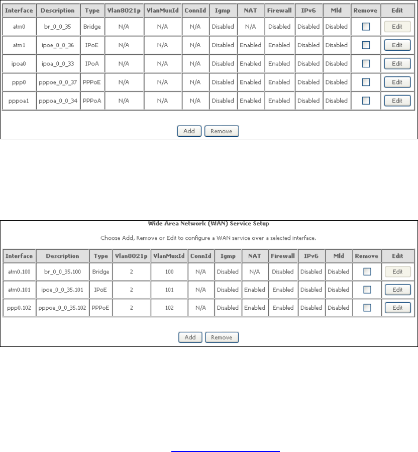
The figure below shows the five connection types available in ATM default mode.
VLAN MUX MODE
This mode uses VLAN tags to allow for multiple connections over a single interface.
PPPoE, IPoE, and Bridge are supported while PPPoA and IPoA connections are not.
The figure below shows multiple connections over a single VLAN Mux interface.
PDF created with pdfFactory Pro trial version www.pdffactory.com

115
MSC MODE
Multi-Service Connection (MSC) mode supports multiple connections over a single
interface. As with VLAN Mux mode, PPPoA and IPoA connection types are not
supported, while Bridging is unavailable for Ethernet WAN interfaces. After adding
WAN connections to an interface, you must also create an Interface Group to
connect LAN/WAN interfaces (see section G3 ~ More About MSC Mode).
G1.1 ATM Interfaces
Follow these procedures to configure an ATM interface.
NOTE: The NEXUSLINK 3111u supports up to 8 ATM interfaces.
STEP 1: Go to Advanced Setup à Layer2 Interface à ATM Interface.
This table is provided here for ease of reference.
Heading Description
Interface WAN interface name.
VPI ATM VPI (0-255)
VCI ATM VCI (32-65535)
DSL Latency {Path0} à portID = 0
{Path1} à port ID = 1
{Path0&1} à port ID = 4
Category ATM service category
Link Type Choose EoA (for PPPoE, IPoE, and Bridge), PPPoA, or IPoA.
Connection Mode Default Mode – Single service over one connection
Vlan Mux Mode – Multiple Vlan service over one connection
MSC Mode – Multiple Service over one Connection
IP QoS Quality of Service (QoS) status
Scheduler Alg The algorithm used to schedule the dequeue behavior.
Queue Weight The weight of the specified queue.
Group Precedence The Precedence of the specified group.
Remove Select items for removal
STEP 2: Click Add to proceed to the next screen.
NOTE: To add WAN connections to one interface type, you must delete existing
connections from the other interface type using the remove button.
PDF created with pdfFactory Pro trial version www.pdffactory.com
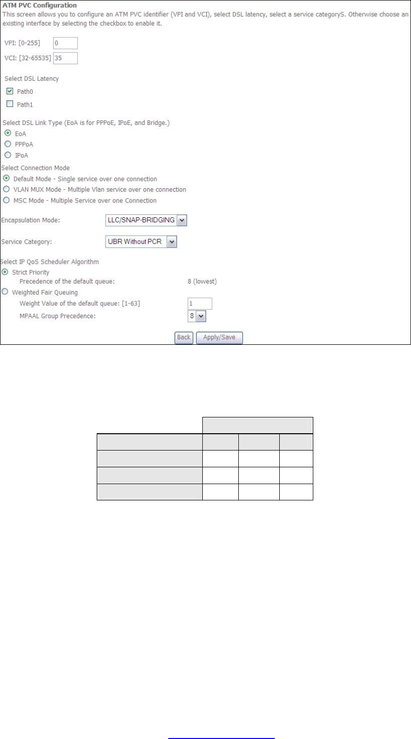
116
There are many settings here including: VPI/VCI, DSL Latency, DSL Link Type,
Encapsulation Mode, Service Category, Connection Mode and Quality of Service.
The table below shows xDSL Link Type availability with each Connection Mode.
xDSL Link Type
Connection Mode
EoA*
PPPoA
IPoA
Default Mode
OK OK OK
VLAN Mux Mode
OK X X
MSC Mode
OK X X
* EoA includes PPPoE, IPoE, and Bridge link types.
Here are the available encapsulations for each xDSL Link Type:
u EoA- LLC/SNAP-BRIDGING, VC/MUX
u PPPoA- VC/MUX, LLC/ENCAPSULATION
u IPoA- LLC/SNAP-ROUTING, VC MUX
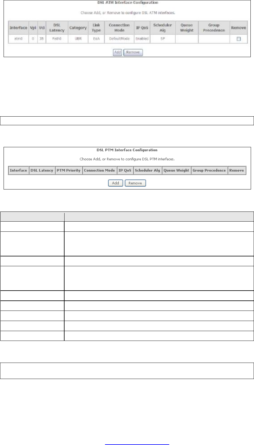
STEP 3: Click Apply/Save to confirm your choices.
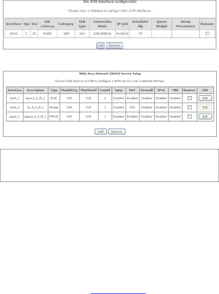
On the next screen, check that the ATM interface is added to the list. For example,
an ATM interface on PVC 0/35 in Default Mode with an EoA Link type is shown below.
PDF created with pdfFactory Pro trial version www.pdffactory.com
117
To add a WAN connection, go to section G2 ~ WAN Connections.
G1.2 PTM Interfaces
Follow these procedures to configure a PTM interface.
NOTE: The NEXUSLINK 3111u supports up to four PTM interfaces.
STEP 4: Go to Advanced Setup à Layer2 Interface à PTM Interface.
This table is provided here for ease of reference.
Heading Description
Interface WAN interface name.
DSL Latency {Path0} à portID = 0
{Path1} à port ID = 1
{Path0&1} à port ID = 4
PTM Priority Normal or High Priority (Preemption).
Connection Mode Default Mode – Single service over one interface.
Vlan Mux Mode – Multiple Vlan services over one interface.
MSC Mode – Multiple Services over one interface.
IP QoS Quality of Service (QoS) status.
Scheduler Alg The algorithm used to schedule the dequeue behavior.
Queue Weight The weight of the specified queue.
Group Precedence The Precedence of the specified group.
Remove Select interfaces to remove.
STEP 5: Click Add to proceed to the next screen.
NOTE: To add WAN connections to one interface type, you must delete existing
connections from the other interface type using the remove button.
PDF created with pdfFactory Pro trial version www.pdffactory.com
118
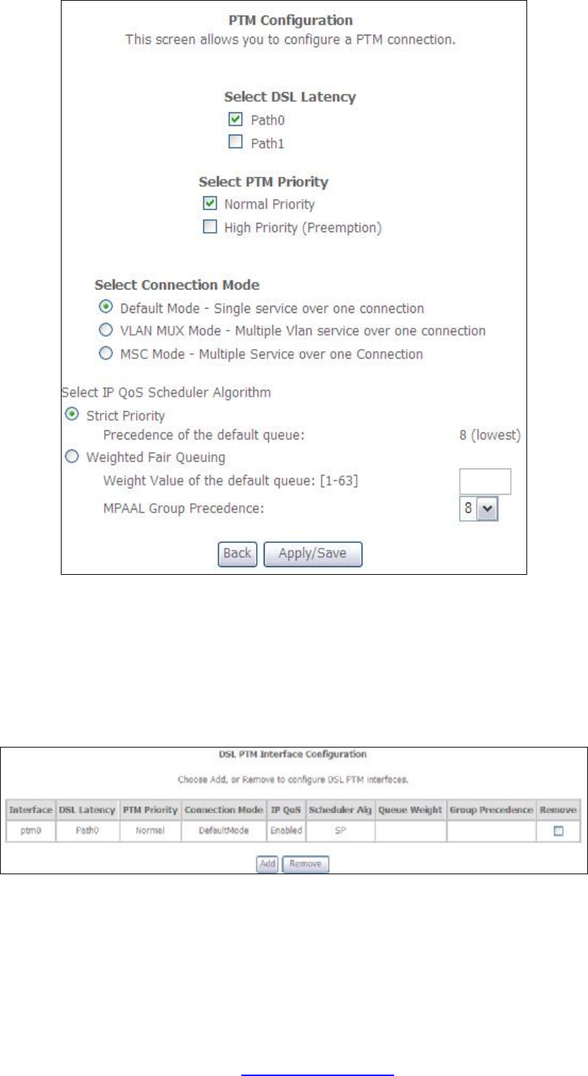
There are many settings that can be configured here including:
DSL Latency, PTM Priority, Connection Mode and Quality of Service.
STEP 6: Click Apply/Save to confirm your choices.
On the next screen, check that the PTM interface is added to the list.
For example, an PTM interface in Default Mode is shown below.
To add a WAN connection, go to section G2 ~ WAN Connections.
PDF created with pdfFactory Pro trial version www.pdffactory.com
119
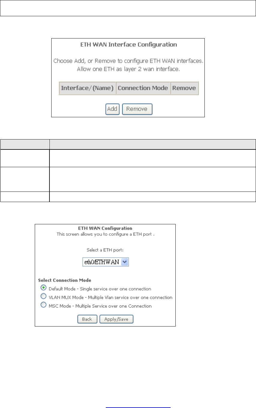
G1.3 Ethernet WAN Interface
Some models of the NEXUSLINK 3111u support a single Ethernet WAN interface
over the ETH WAN port. Follow these procedures to configure an Ethernet WAN
interface.
NOTE: To add WAN connections to one interface type, you must delete existing
connections from the other interface type using the remove button.
STEP 1: Go to Advanced Setup à Layer2 Interface à ETH Interface.
This table is provided here for ease of reference.
Heading Description
Interface/
(Name) ETH WAN Interface
Connection
Mode Default Mode – Single service over one connection
Vlan Mux Mode – Multiple Vlan service over one connection
MSC Mode – Multiple Service over one Connection
Remove Select the checkbox and click Remove to remove the connection.
STEP 2: Click Add to proceed to the next screen.
STEP 3: Select a Connection Mode from the options shown above.
STEP 4: Click Apply/Save to confirm your choice.
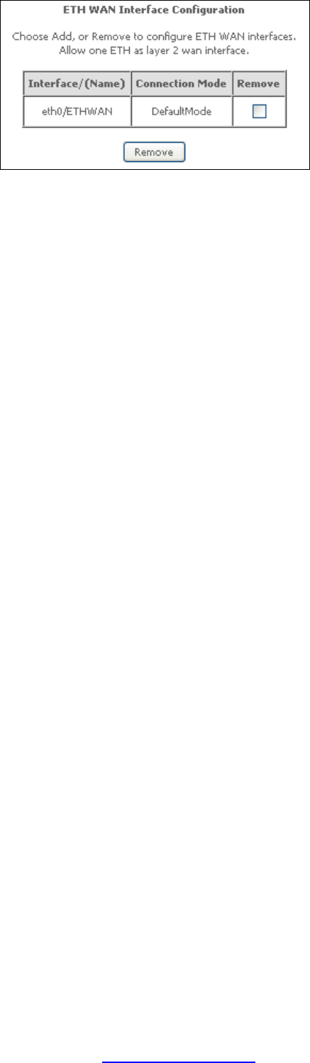
The figure below shows an Ethernet WAN interface configured in Default Mode.
PDF created with pdfFactory Pro trial version www.pdffactory.com
121
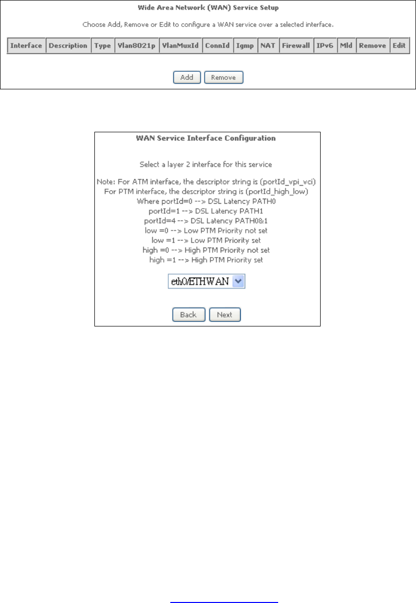
G2 ~ WAN Connections
In Default Mode, the NEXUSLINK 3111u supports one WAN connection for each
interface, up to a maximum of 8 connections. VLAN Mux and MSC support up to 16
connections.
To setup a WAN connection follow these instructions.
STEP 1: Go to the Advanced Setup à WAN Service screen.
STEP 2: Click Add to create a WAN connection. The following screen will display.
PDF created with pdfFactory Pro trial version www.pdffactory.com
122
STEP 3: Choose a layer 2 interface from the drop-down box and click Next.
The WAN Service Configuration screen will display as shown below.
NOTE: The WAN services shown here are those supported by the layer 2
interface you selected in the previous step. If you wish to change your
selection click the Back button and select a different layer 2 interface.
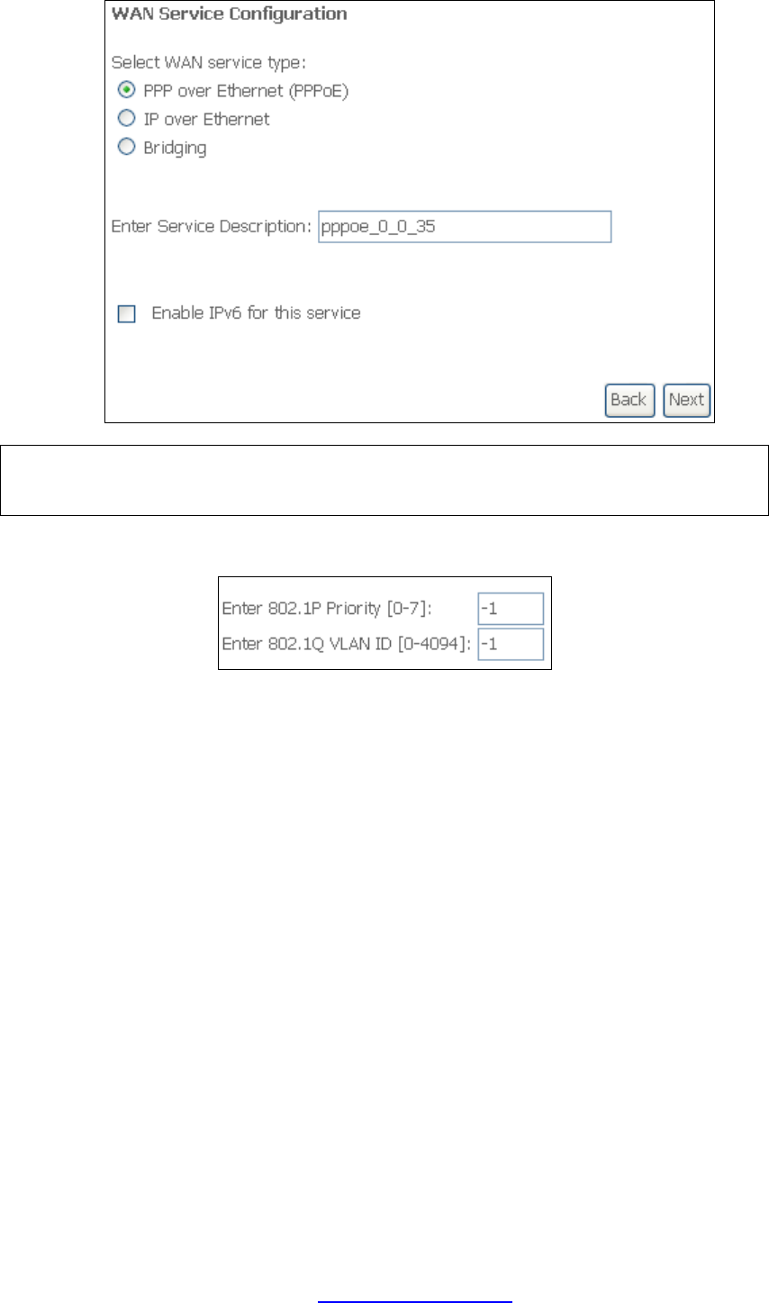
STEP 4: For VLAN Mux Connections only, you must enter Priority & VLAN ID tags.
STEP 5: You will now follow the instructions specific to the WAN service type you
wish to establish. This list should help you locate the correct procedure:
(1) For G2.1 PPP over ETHERNET (PPPoE), go to page 123.
(2) For G2.2 IP over ETHERNET (IPoE), go to page 128.
(3) For G2.3 Bridging, go to page 133.
(4) For G2.4 PPP over ATM (PPPoA), go to page 134.
(5) For G2.5 IP over ATM (IPoA), go to page 137.
The subsections that follow continue the WAN service setup procedure.
PDF created with pdfFactory Pro trial version www.pdffactory.com
123
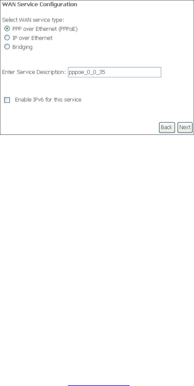
G2.1 PPP over ETHERNET (PPPoE)
STEP 1: Select the PPP over Ethernet radio button and click Next. You can also
enable IPv6 by ticking the checkbox þ at the bottom of this screen.
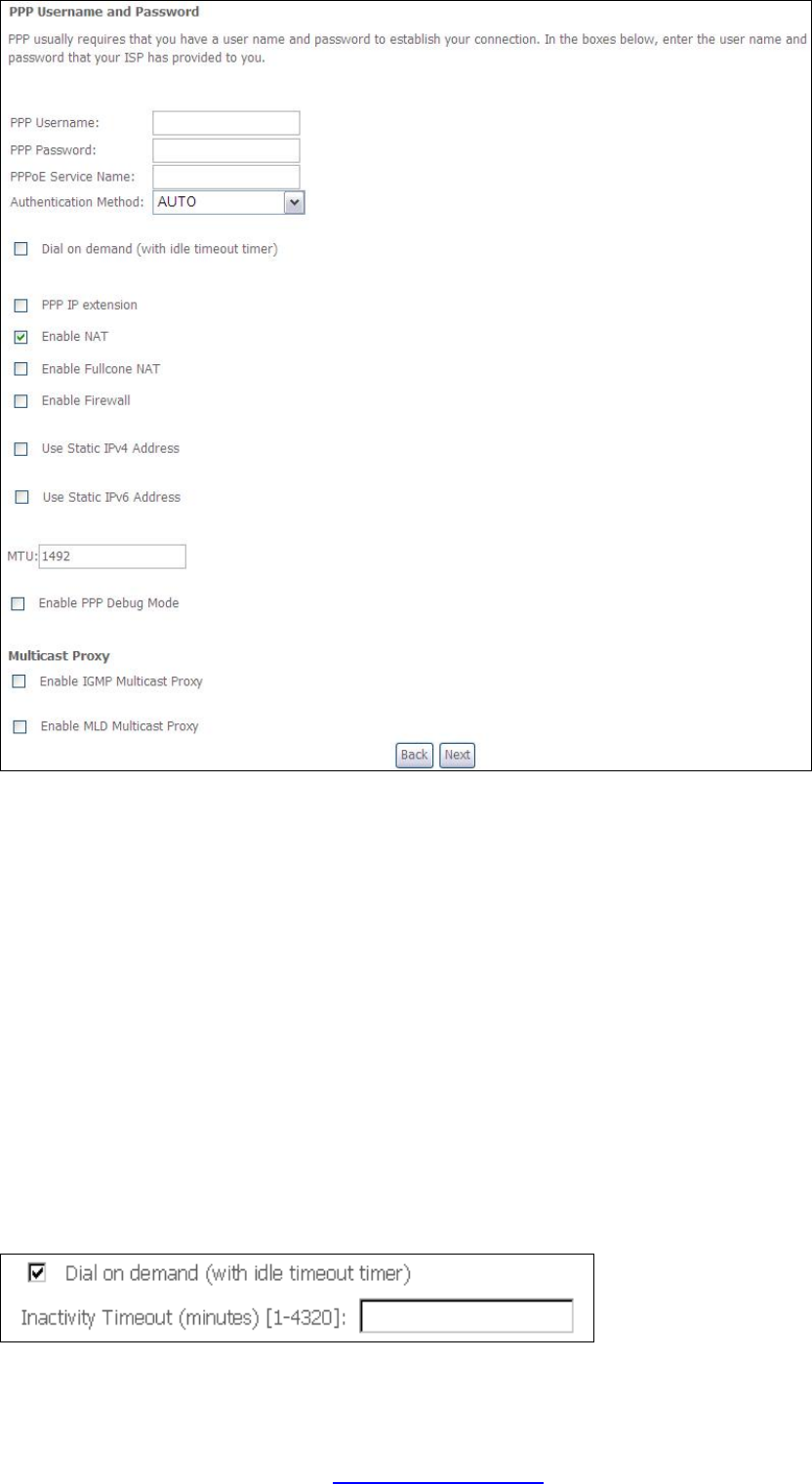
STEP 2: On the next screen, enter the PPP settings as provided by your ISP.
Click Next to continue or click Back to return to the previous step.
PDF created with pdfFactory Pro trial version www.pdffactory.com
124
The settings shown above are described below.
PPP SETTINGS
The PPP Username, PPP password and the PPPoE Service Name entries are
dependent on the particular requirements of the ISP. The user name can be a
maximum of 256 characters and the password a maximum of 32 characters in
length. For Authentication Method, choose from AUTO, PAP, CHAP, and MSCHAP.
ENABLE FULLCONE NAT
This option becomes available when NAT is enabled. Known as one-to-one NAT, all
requests from the same internal IP address and port are mapped to the same
external IP address and port. An external host can send a packet to the internal host,
by sending a packet to the mapped external address.
DIAL ON DEMAND
The NEXUSLINK 3111u can be configured to disconnect if there is no activity for a
period of time by selecting the Dial on demand checkbox þ. You must also enter
an inactivity timeout period in the range of 1 to 4320 minutes.
PDF created with pdfFactory Pro trial version www.pdffactory.com

125
PPP IP EXTENSION
The PPP IP Extension is a special feature deployed by some service providers.
Unless your service provider specifically requires this setup, do not select it.
PPP IP Extension does the following:
• Allows only one PC on the LAN.
• Disables NAT and Firewall.
• The device becomes the default gateway and DNS server to the PC
through DHCP using the LAN interface IP address.
• The device extends the IP subnet at the remote service provider to the
LAN PC. i.e. the PC becomes a host belonging to the same IP subnet.
• The device bridges the IP packets between WAN and LAN ports, unless
the packet is addressed to the device’s LAN IP address.
• The public IP address assigned by the remote side using the PPP/IPCP
protocol is actually not used on the WAN PPP interface. Instead, it is
forwarded to the PC LAN interface through DHCP. Only one PC on the
LAN can be connected to the remote, since the DHCP server within the
device has only a single IP address to assign to a LAN device.
ENABLE NAT
If the LAN is configured with a private IP address, the user should select this
checkbox þ. The NAT submenu will appear in the Advanced Setup menu after reboot.
On the other hand, if a private IP address is not used on the LAN side (i.e. the LAN
side is using a public IP), this checkbox þ should not be selected to free up system
resources for better performance.
ENABLE FIREWALL
If this checkbox þ is selected, the Security submenu will be displayed on the
Advanced Setup menu after reboot. If firewall is not necessary, this checkbox þ
should not be selected to free up system resources for better performance.
USE STATIC IPv4 ADDRESS
Unless your service provider specially requires it, do not select this checkbox þ. If
selected, enter the static IP address in the IPv4 Address field. Don’t forget to
adjust the IP configuration to Static IP Mode as described in 3.2 IP Configuration.
USE STATIC IPv6 ADDRESS
This option displays when IPv6 is enabled. Unless your service provider specially
requires it, do not select this checkbox þ. If selected, enter the static IP address in
the IPv6 Address field along with a value for Prefix Length. Don’t forget to adjust
the IP configuration to Static IP Mode as described in 3.2 IP Configuration.
MTU
Maximum Transmission Unit. The size (in bytes) of largest protocol data unit which
the layer can pass onwards. This value is 1492 for PPPoE.
ENABLE PPP DEBUG MODE
When this option is selected, the system will put more PPP connection information
into the system log. This is for debugging errors and not for normal usage.
PDF created with pdfFactory Pro trial version www.pdffactory.com
126
ENABLE IGMP MULTICAST PROXY
Tick the checkbox þ to enable Internet Group Membership Protocol (IGMP)
multicast. This protocol is used by IPv4 hosts to report their multicast group
memberships to any neighboring multicast routers.
ENABLE MLD MULTICAST PROXY
This option displays when IPv6 is enabled. Tick the checkbox þ to enable Multicast
Listener Discovery (MLD). This protocol is used by IPv6 hosts to report their
multicast group memberships to any neighboring multicast routers.
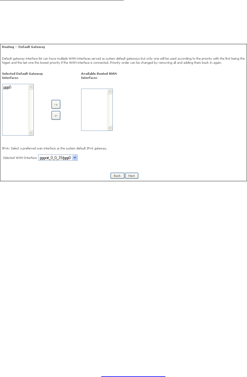
STEP 3: Choose an interface to be the default gateway.
Click Next to continue or click Back to return to the previous step.
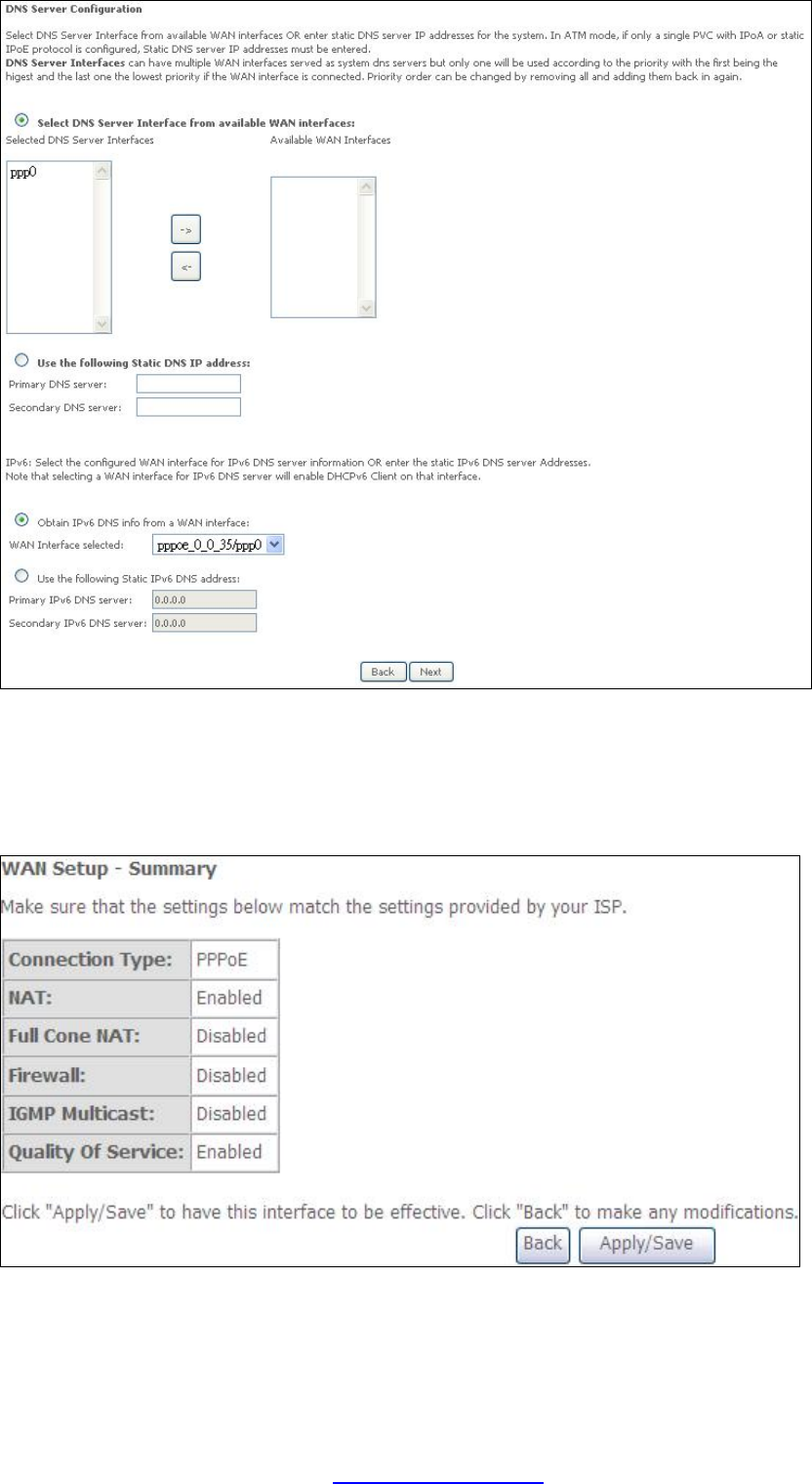
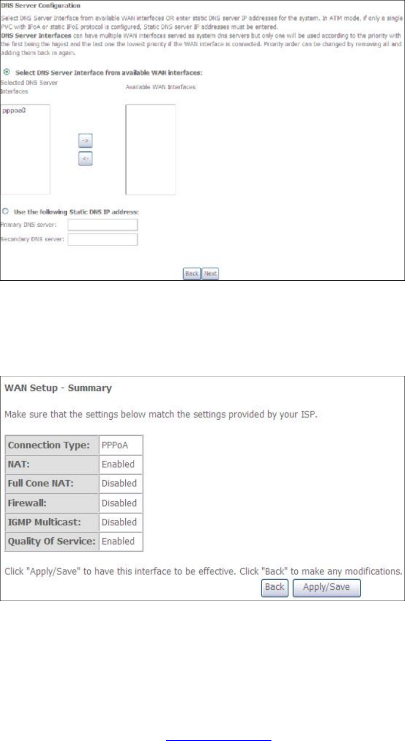
STEP 4:
Select DNS Server Interface from available WAN interfaces OR enter static DNS
server IP addresses for the system. In ATM mode, if only a single PVC with IPoA or
static IPoE protocol is configured, Static DNS server IP addresses must be entered.
PDF created with pdfFactory Pro trial version www.pdffactory.com
127
Click Next to continue or click Back to return to the previous step.
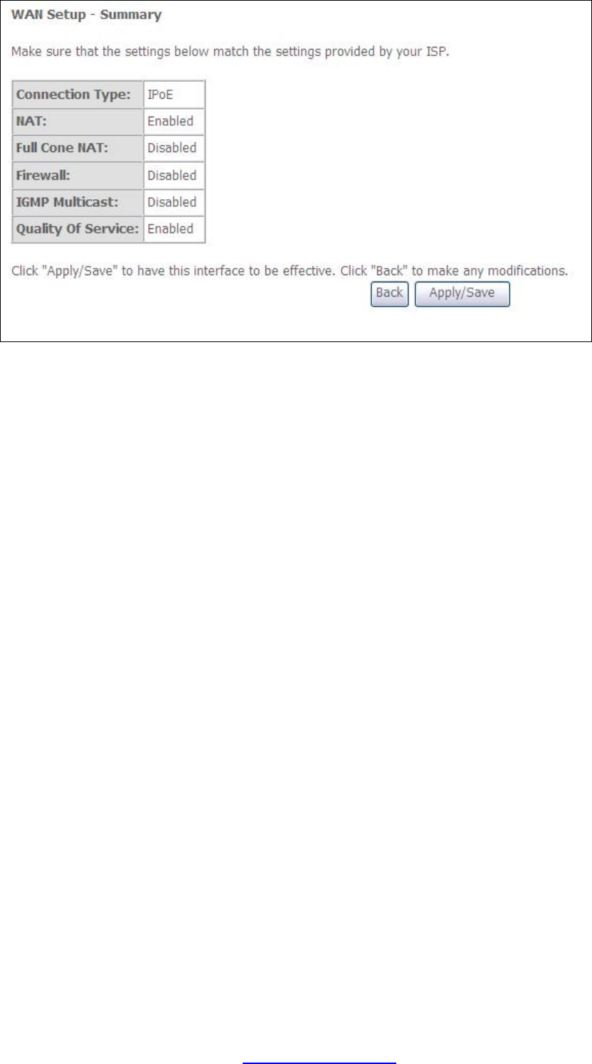
STEP 5: The WAN Setup - Summary screen shows a preview of the WAN service
you have configured. Check these settings and click Apply/Save if they
are correct, or click Back to modify them.
After clicking Apply/Save, the new service should appear on the main screen.
To activate it you must reboot. Go to Management à Reboot and click Reboot.
PDF created with pdfFactory Pro trial version www.pdffactory.com
128
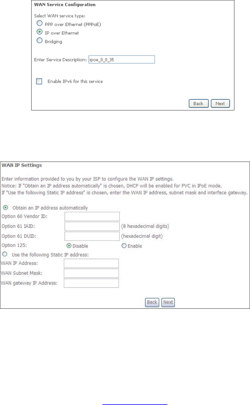
G2.2 IP over ETHERNET (IPoE)
STEP 1: Select the IP over Ethernet radio button and click Next. You can also
enable IPv6 by ticking the checkbox þ at the bottom of this screen.
STEP 2: The WAN IP settings screen provides access to the DHCP server settings.
You can select the Obtain an IP address automatically radio button to
enable DHCP (use the DHCP Options only if necessary). However, if you
prefer, you can instead use the Static IP address method to assign WAN
IP address, Subnet Mask and Default Gateway manually.
PDF created with pdfFactory Pro trial version www.pdffactory.com
129
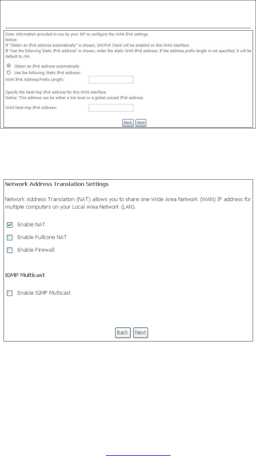
NOTE: If IPv6 networking is enabled, an additional set of instructions, radio
buttons, and text entry boxes will appear at the bottom of the screen.
These configuration options are quite similar to those for IPv4 networks.
Click Next to continue or click Back to return to the previous step.
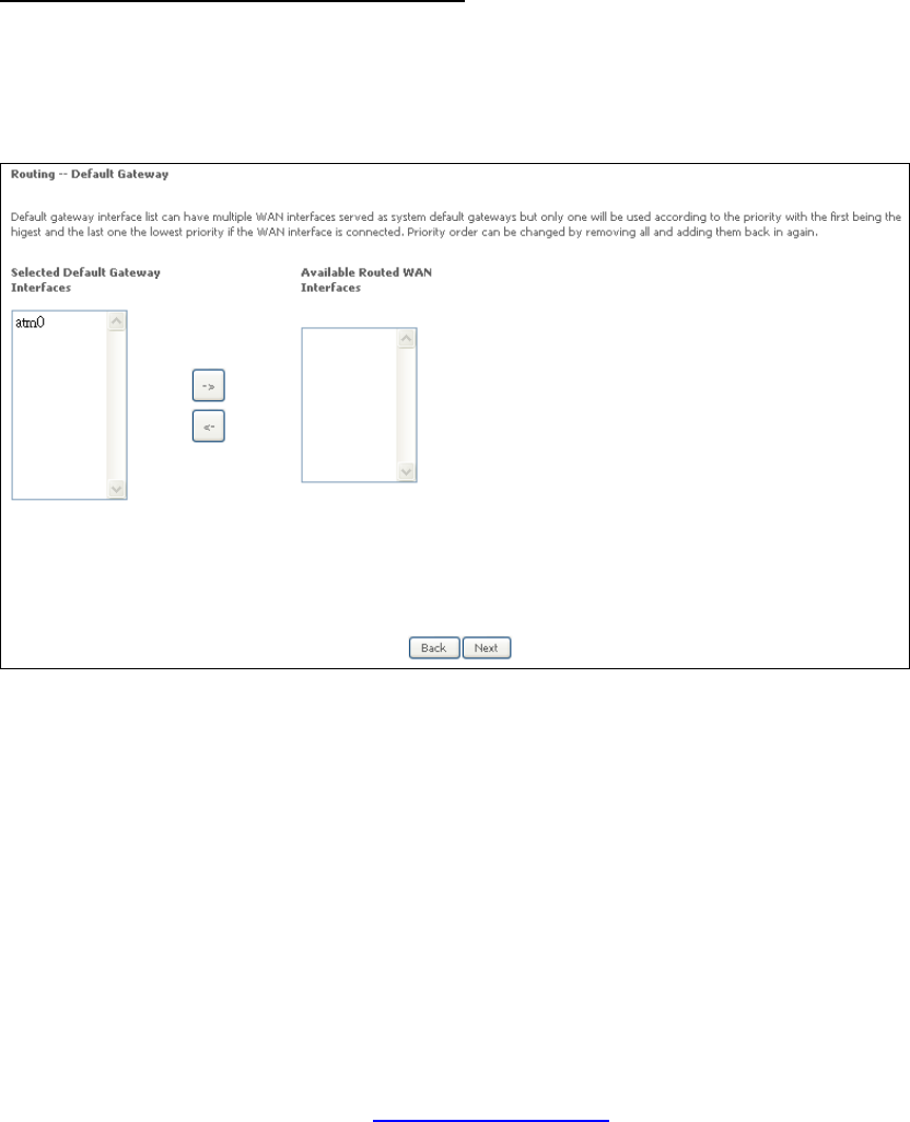
STEP 3: This screen provides access to NAT, Firewall and IGMP Multicast settings.
Enable each by selecting the appropriate checkbox þ. Click Next to
continue or click Back to return to the previous step.
ENABLE NAT
If the LAN is configured with a private IP address, the user should select this
checkbox þ. The NAT submenu will appear in the Advanced Setup menu after
reboot. On the other hand, if a private IP address is not used on the LAN side (i.e.
the LAN side is using a public IP), this checkbox þ should not be selected, so as to
free up system resources for improved performance.
PDF created with pdfFactory Pro trial version www.pdffactory.com
130
ENABLE FULLCONE NAT
This option becomes available when NAT is enabled. Known as one-to-one NAT, all
requests from the same internal IP address and port are mapped to the same
external IP address and port. An external host can send a packet to the internal host,
by sending a packet to the mapped external address.
ENABLE FIREWALL
If this checkbox þ is selected, the Security submenu will be displayed on the
Advanced Setup menu after reboot. If firewall is not necessary, this checkbox þ
should not be selected so as to free up system resources for better performance.
ENABLE IGMP MULTICAST
Tick the checkbox þ to enable Internet Group Membership Protocol (IGMP)
multicast. IGMP is a protocol used by IPv4 hosts to report their multicast group
memberships to any neighboring multicast routers.
ENABLE MLD MULTICAST PROXY
This option displays when IPv6 is enabled. Tick the checkbox þ to enable Multicast
Listener Discovery (MLD). This protocol is used by IPv6 hosts to report their
multicast group memberships to any neighboring multicast routers.
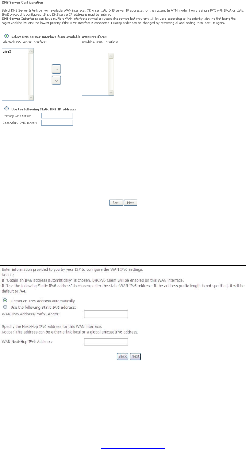
STEP 4: Choose an interface to be the default gateway.
Click Next to continue or click Back to return to the previous step.
STEP 5:
Select DNS Server Interface from available WAN interfaces OR enter static DNS
server IP addresses for the system. In ATM mode, if only a single PVC with IPoA or
static IPoE protocol is configured, Static DNS server IP addresses must be entered.
PDF created with pdfFactory Pro trial version www.pdffactory.com
131
Click Next to continue or click Back to return to the previous step.
If IPv6 is enabled, an additional set of options will be shown.
Click Next to continue or click Back to return to the previous step.
STEP 6: The WAN Setup - Summary screen shows a preview of the WAN service
you have configured. Check these settings and click Apply/Save if they
are correct, or click Back to modify them.
PDF created with pdfFactory Pro trial version www.pdffactory.com
133
G2.3 Bridging
NOTE: This connection type is not available on the Ethernet WAN interface.
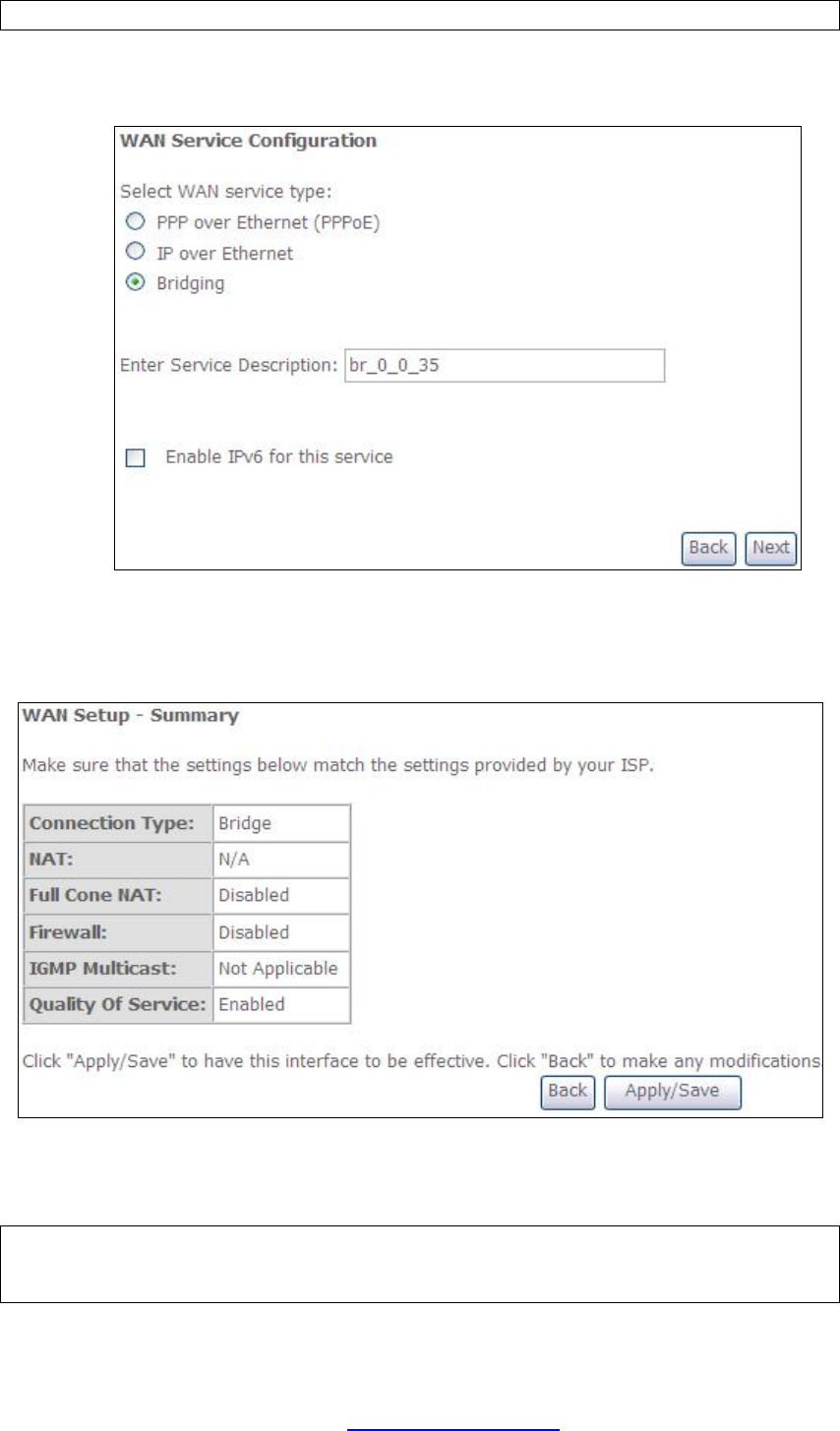
STEP 1: Select the Bridging radio button and click Next. You can also enable IPv6
by ticking the checkbox þ at the bottom of this screen.
STEP 2: The WAN Setup - Summary screen shows a preview of the WAN service
you have configured. Check these settings and click Apply/Save if they
are correct, or click Back to return to the previous screen.
After clicking Apply/Save, the new service should appear on the main screen.
To activate it you must reboot. Go to Management à Reboot and click Reboot.
NOTE: If this bridge connection is your only WAN service, the NEXUSLINK 3111u
will be inaccessible for remote management or technical support from the
WAN.
PDF created with pdfFactory Pro trial version www.pdffactory.com
134
G2.4 PPP over ATM (PPPoA)
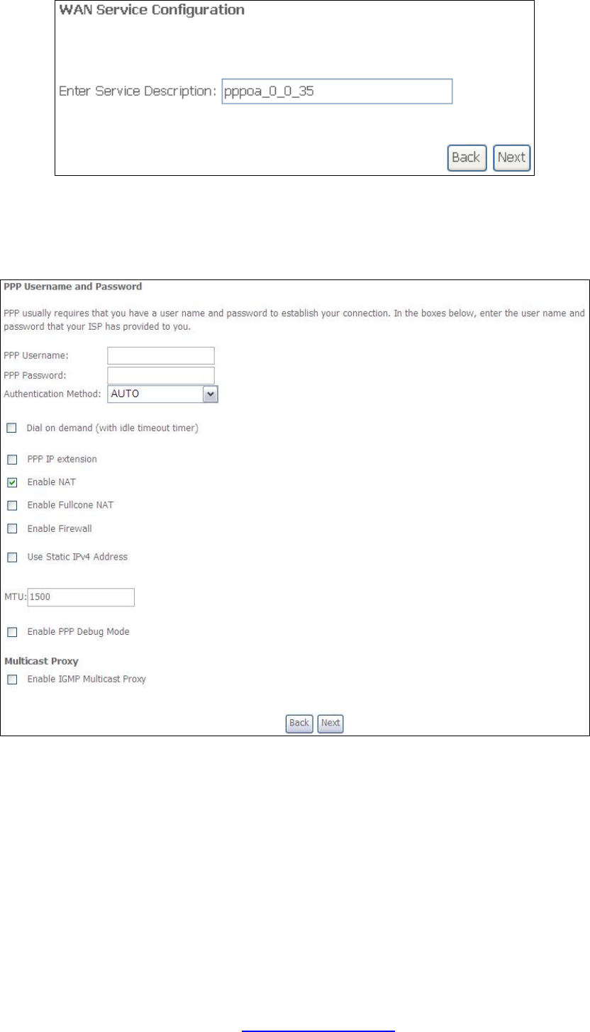
STEP 1: Click Next to continue.
STEP 2: On the next screen, enter the PPP settings as provided by your ISP.
Click Next to continue or click Back to return to the previous step.
PPP SETTINGS
The PPP username and password are dependent on the requirements of the ISP.
The user name can be a maximum of 256 characters and the password a maximum
of 32 characters in length. (Authentication Method: AUTO, PAP, CHAP, or MSCHAP.)
DIAL ON DEMAND
The NEXUSLINK 3111u can be configured to disconnect if there is no activity for a
period of time by selecting the Dial on demand checkbox þ. You must also enter
an inactivity timeout period in the range of 1 to 4320 minutes.
PDF created with pdfFactory Pro trial version www.pdffactory.com

135
PPP IP EXTENSION
The PPP IP Extension is a special feature deployed by some service providers.
Unless your service provider specifically requires this setup, do not select it.
PPP IP Extension does the following:
• Allows only one PC on the LAN.
• Disables NAT and Firewall.
• The device becomes the default gateway and DNS server to the PC
through DHCP using the LAN interface IP address.
• The device extends the IP subnet at the remote service provider to the
LAN PC. i.e. the PC becomes a host belonging to the same IP subnet.
• The device bridges the IP packets between WAN and LAN ports, unless
the packet is addressed to the device’s LAN IP address.
• The public IP address assigned by the remote side using the PPP/IPCP
protocol is actually not used on the WAN PPP interface. Instead, it is
forwarded to the PC LAN interface through DHCP. Only one PC on the
LAN can be connected to the remote, since the DHCP server within the
device has only a single IP address to assign to a LAN device.
ENABLE NAT
If the LAN is configured with a private IP address, the user should select this
checkbox þ. The NAT submenu will appear in the Advanced Setup menu after reboot.
On the other hand, if a private IP address is not used on the LAN side (i.e. the LAN
side is using a public IP), this checkbox þ should not be selected to free up system
resources for better performance.
ENABLE FULLCONE NAT
This option becomes available when NAT is enabled. Known as one-to-one NAT, all
requests from the same internal IP address and port are mapped to the same
external IP address and port. An external host can send a packet to the internal host,
by sending a packet to the mapped external address.
ENABLE FIREWALL
If this checkbox þ is selected, the Security submenu will be displayed on the
Advanced Setup menu after reboot. If firewall is not necessary, this checkbox þ
should not be selected to free up system resources for better performance.
USE STATIC IPv4 ADDRESS
Unless your service provider specially requires it, do not select this checkbox þ. If
selected, enter the static IP address in the IP Address field. Also, don’t forget to
adjust the IP configuration to Static IP Mode as described in 3.2 IP Configuration.
MTU
Maximum Transmission Unit. The size (in bytes) of largest protocol data unit which
the layer can pass onwards. This value is 1500 for PPPoA.
ENABLE PPP DEBUG MODE
When this option is selected, the system will put more PPP connection information
into the system log. This is for debugging errors and not for normal usage.
PDF created with pdfFactory Pro trial version www.pdffactory.com
136
ENABLE IGMP MULTICAST PROXY
Tick the checkbox þ to enable Internet Group Membership Protocol (IGMP)
multicast. IGMP is a protocol used by IPv4 hosts to report their multicast group
memberships to any neighboring multicast routers.
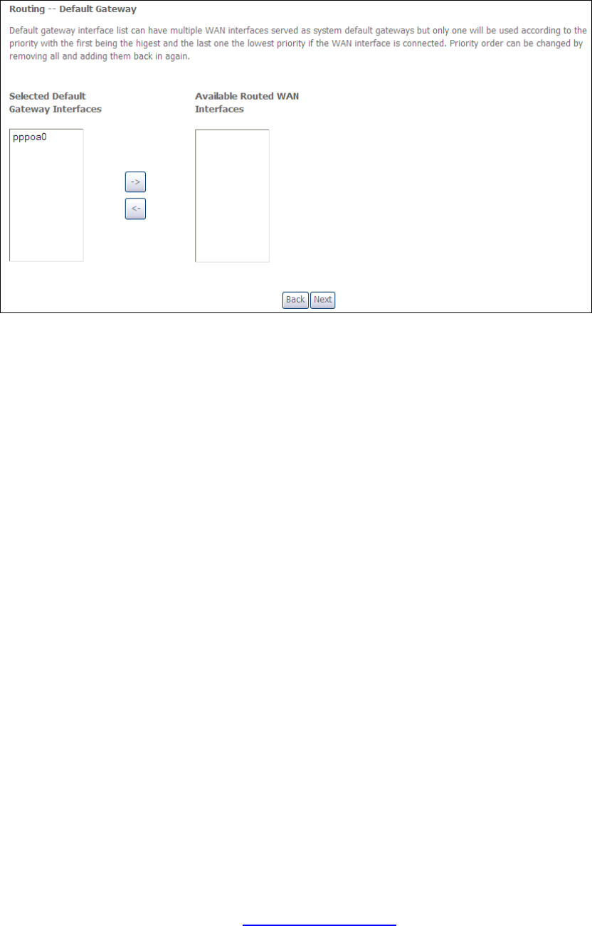
STEP 3: Choose an interface to be the default gateway.
Click Next to continue or click Back to return to the previous step.
STEP 4:
Select DNS Server Interface from available WAN interfaces OR enter static DNS
server IP addresses for the system. In ATM mode, if only a single PVC with IPoA or
static IPoE protocol is configured, Static DNS server IP addresses must be entered.
PDF created with pdfFactory Pro trial version www.pdffactory.com
137
Click Next to continue or click Back to return to the previous step.
STEP 5: The WAN Setup - Summary screen shows a preview of the WAN service
you have configured. Check these settings and click Apply/Save if they
are correct, or click Back to modify them.
After clicking Apply/Save, the new service should appear on the main screen.
To activate it you must reboot. Go to Management à Reboot and click Reboot.
PDF created with pdfFactory Pro trial version www.pdffactory.com
138
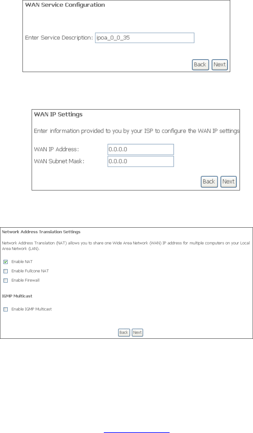
G2.5 IP over ATM (IPoA)
STEP 1: Click Next to continue.
STEP 2: Enter the WAN IP settings provided by your ISP. Click Next to continue.
STEP 3: This screen provides access to NAT, Firewall and IGMP Multicast settings.
Enable each by selecting the appropriate checkbox þ. Click Next to
continue or click Back to return to the previous step.
ENABLE NAT
If the LAN is configured with a private IP address, the user should select this
checkbox þ. The NAT submenu will appear in the Advanced Setup menu after
reboot. On the other hand, if a private IP address is not used on the LAN side (i.e.
the LAN side is using a public IP), this checkbox þ should not be selected, so as to
free up system resources for improved performance.
PDF created with pdfFactory Pro trial version www.pdffactory.com
139
ENABLE FULLCONE NAT
This option becomes available when NAT is enabled. Known as one-to-one NAT, all
requests from the same internal IP address and port are mapped to the same
external IP address and port. An external host can send a packet to the internal host
by sending a packet to the mapped external address.
ENABLE FIREWALL
If this checkbox þ is selected, the Security submenu will be displayed on the
Advanced Setup menu after reboot. If firewall is not necessary, this checkbox þ
should not be selected so as to free up system resources for better performance.
ENABLE IGMP MULTICAST
Tick the checkbox þ to enable Internet Group Membership Protocol (IGMP)
multicast. IGMP is a protocol used by IPv4 hosts to report their multicast group
memberships to any neighboring multicast routers.
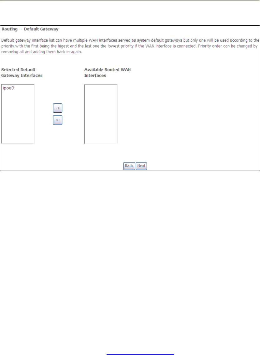
STEP 4: Choose an interface to be the default gateway.
Click Next to continue or click Back to return to the previous step.
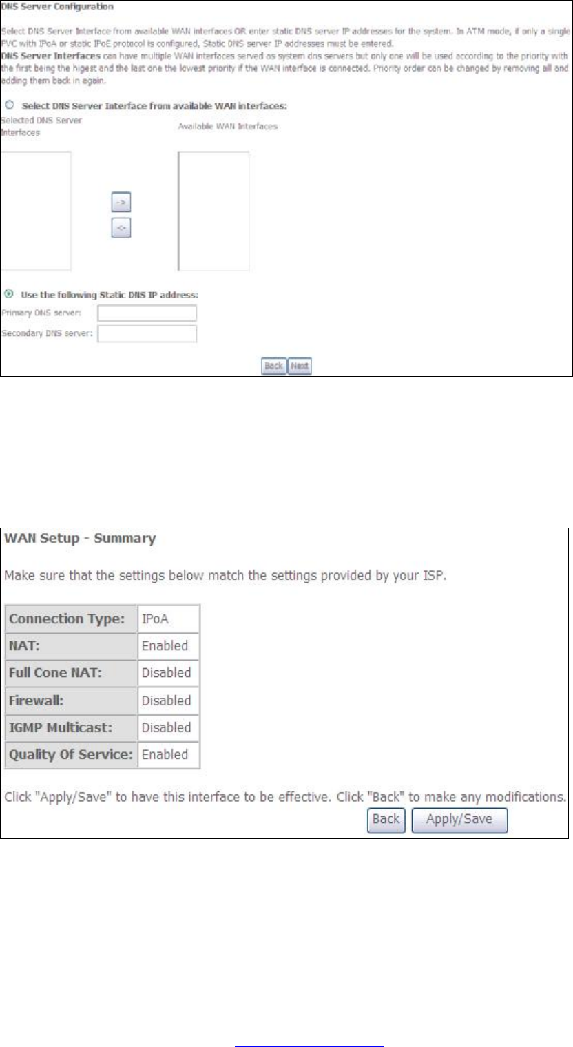
STEP 5:
Select DNS Server Interface from available WAN interfaces OR enter static DNS
server IP addresses for the system. In ATM mode, if only a single PVC with IPoA or
static IPoE protocol is configured, Static DNS server IP addresses must be entered.
PDF created with pdfFactory Pro trial version www.pdffactory.com
140
Click Next to continue or click Back to return to the previous step.
STEP 7: The WAN Setup - Summary screen shows a preview of the WAN service
you have configured. Check these settings and click Apply/Save if they
are correct, or click Back to modify them.
After clicking Apply/Save, the new service should appear on the main screen.
To activate it you must reboot. Go to Management à Reboot and click Reboot.
PDF created with pdfFactory Pro trial version www.pdffactory.com
141
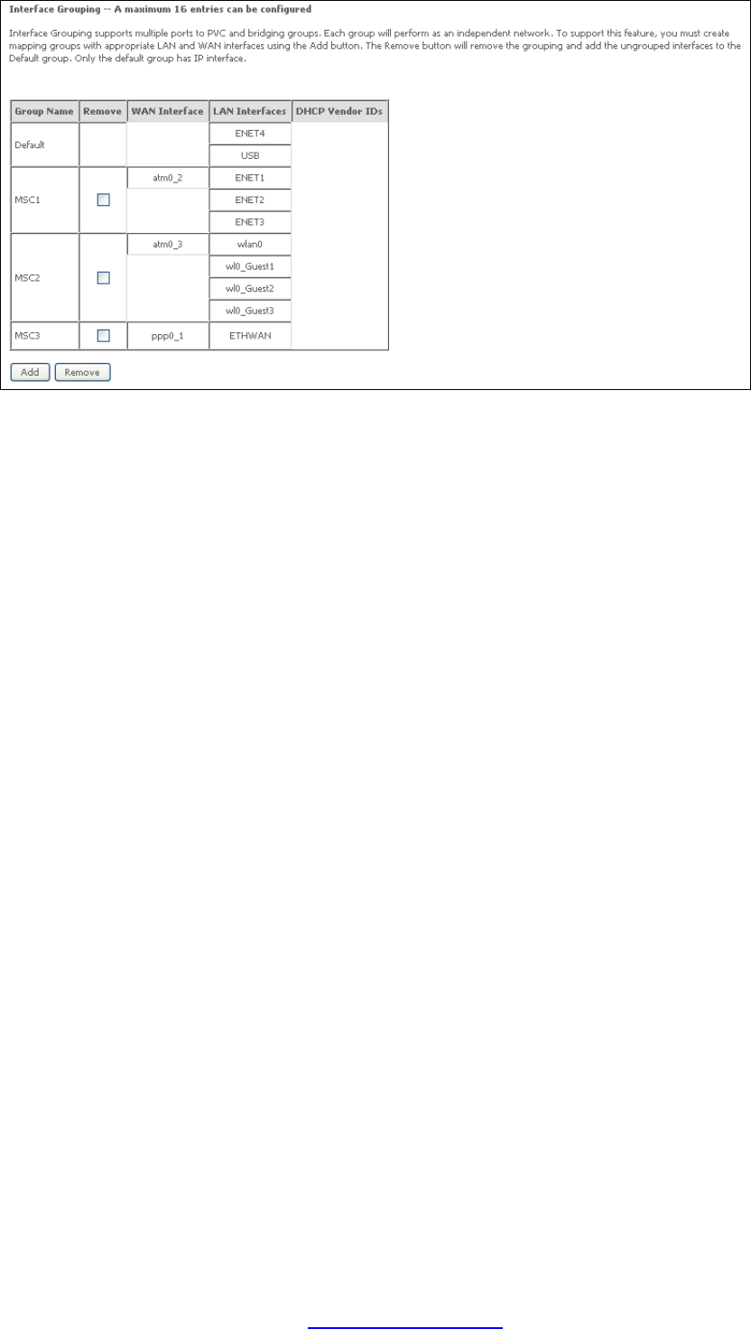
G3 ~ More About MSC Mode
The procedure for WAN connection setup in MSC mode is as follows:
STEP 1: Create a Layer2 interface in MSC connection mode.
STEP 2: Add WAN connections to the interface (Bridge, PPPoE or IPoE).
STEP 3: Use 5.16 Interface Grouping to connect LAN and WAN interfaces.
These three steps are repeated below with screenshots added for reference.
STEP 1: Create a Layer2 interface in MSC connection mode.
STEP 2: Add WAN connections to the interface (Bridge, PPPoE or IPoE).
NOTES: If QoS is configured on the first MSC connection, it will be configured by
default for all subsequent connections.
If a MSC connection is removed every other MSC connection should be
removed to avoid potential configuration problems.
PDF created with pdfFactory Pro trial version www.pdffactory.com