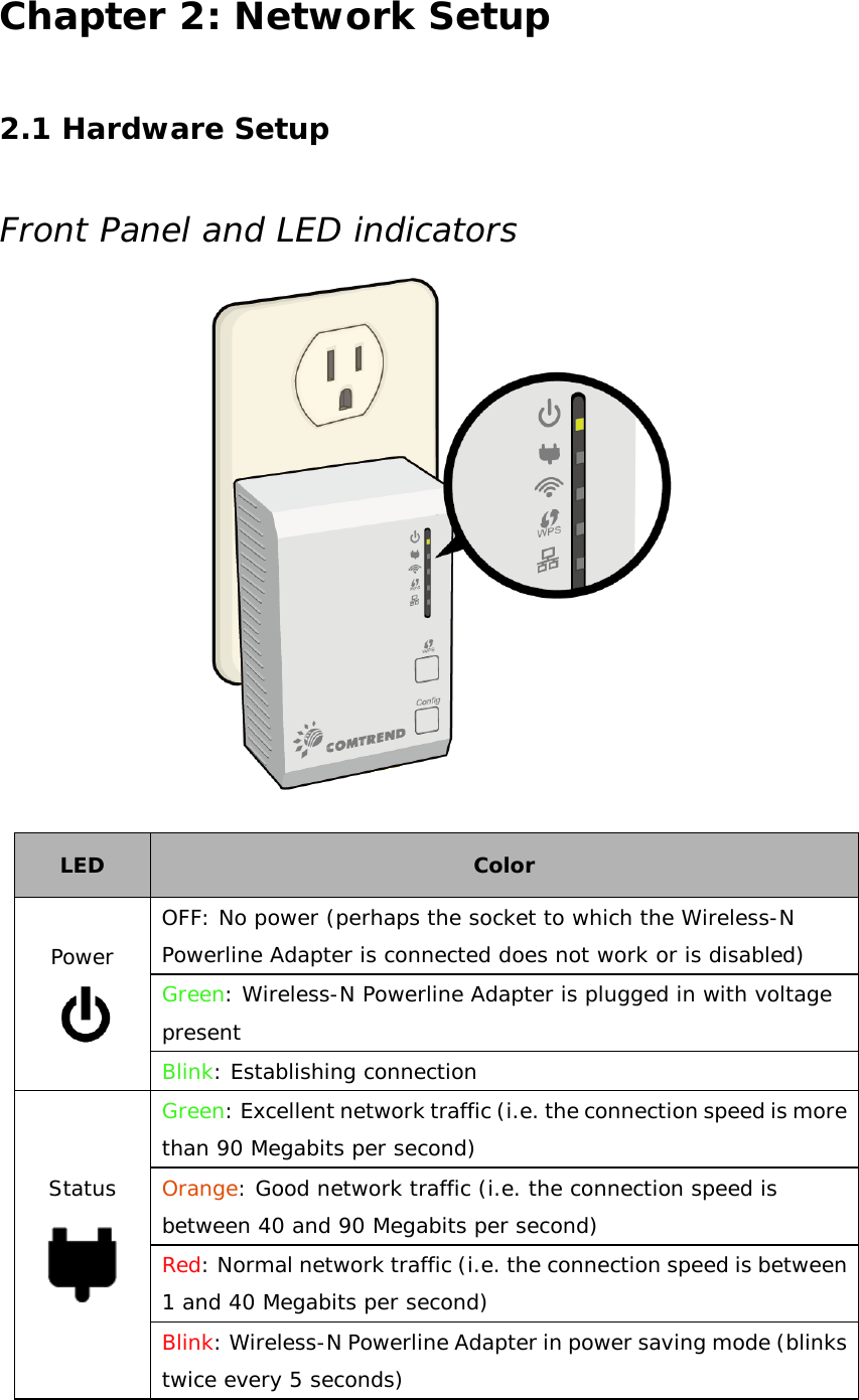
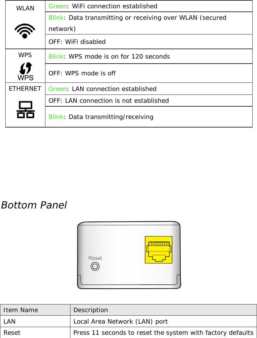
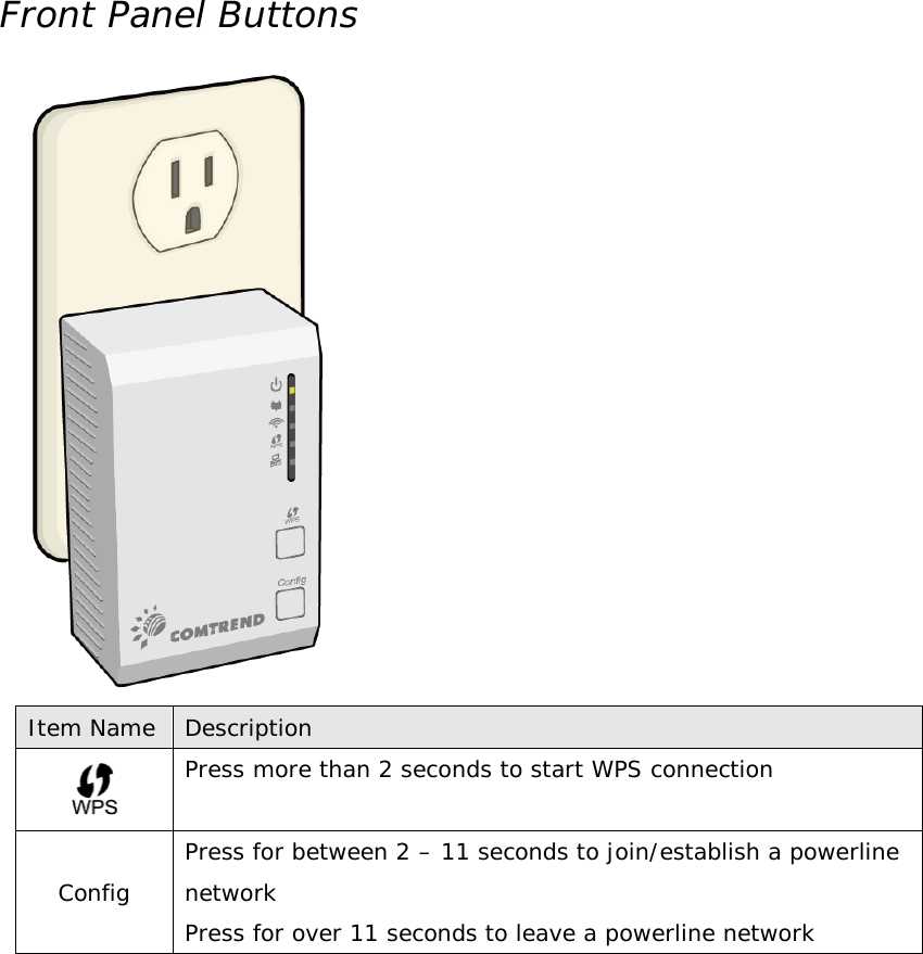
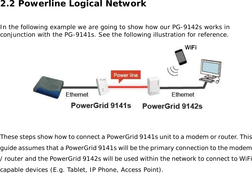
Comtrend PG-9142S Powerline Ethernet Adapter with WiFi User Manual

Comtrend Corporation Powerline Ethernet Adapter with WiFi

User manual

1    PowerGrid 9142s    Powerline Ethernet Adapter   with WiFi   User Manual    Version A1.0, October 2, 2014      261072-025
 Preface This manual provides information related to the installation and operation of this device.  The individual reading this manual is presumed to have a basic understanding of telecommunications terminology and concepts.    If you find the product to be inoperable or malfunctioning, please contact technical support for immediate service by email at INT-support@comtrend.com  For product update, new product release, manual revision, or software upgrades, please visit our website at http://www.comtrend.com Copyright Copyright©2014 Comtrend Corporation.  All rights reserved.  The information contained herein is proprietary to Comtrend Corporation.   No part of this document may be translated, transcribed, reproduced, in any form, or by any means without prior written consent of Comtrend Corporation.  This program is free software: you can redistribute it and/or modify it under the terms of the GNU General Public License as published by the Free Software Foundation, either version 3 of the License, or (at your option) any later version.  This program is distributed in the hope that it will be useful, but WITHOUT ANY WARRANTY; without even the implied warranty of MERCHANTABILITY or FITNESS FOR A PARTICULAR PURPOSE.  See the GNU General Public License for more details.  You should have received a copy of the GNU General Public License along with this program.  If not, see http://www.gnu.org/licenses/     NOTE:    This document is subject to change without notice. Protect Our Environment This symbol indicates that when the equipment has reached the end of  its useful life, it must be taken to a recycling centre and processed  separate from domestic waste.  The cardboard box, the plastic contained in the packaging, and the parts that make up this router can be recycled in accordance with regionally established regulations.   Never dispose of this electronic equipment along with your household waste; you may be subject to penalties or sanctions under the law.  Instead, please be responsible and ask for disposal instructions from your local government.
Federal Communication Commission Interference StatementThis equipment has been tested and found to comply with the limits for a Class B digital device,pursuant to Part 15 of the FCC Rules. These limits are designed to provide reasonableprotection against harmful interference in a residential installation. This equipment generates,uses, and can radiate radio frequency energy and, if not installed and used in accordance withthe instructions, may cause harmful interference to radio communications. However, there isno guarantee that interference will not occur in a particular installation. If this equipment doescause harmful interference to radio or television reception, which can be determined by turningthe equipment off and on, the user is encouraged to try to correct the interference by one ormore of the following measures:• Reorient or relocate the receiving antenna.• Increase the separation between the equipment and receiver.• Connect the equipment into an outlet on a circuit different from that to which the receiver isconnected.• Consult the dealer or an experienced radio/TV technician for help.FCC Caution:This device complies with Part 15 of the FCC Rules. Operation is subject to the following twoconditions: (1) This device may not cause harmful interference, and (2) this device mustaccept any interference received, including interference that may cause undesired operation.Non-modification Statement:Changes or modifications not expressly approved by the party responsible for compliancecould void the user's authority to operate the equipment.FCC Radiation Exposure Statement:This equipment complies with FCC radiation exposure limits set forth for an uncontrolledenvironment. This equipment should be installed and operated with minimum distance 20cmbetween the radiator & your body.
 CHAPTER 1: PRODUCT INFORMATION ................................................................................................ 5 1.1 WIFI FEATURES .................................................................................................................................. 5 1.2 POWERLINE FEATURES ......................................................................................................................... 5 1.3 SAFETY INFORMATION .......................................................................................................................... 6 1.4 SYSTEM REQUIREMENTS ....................................................................................................................... 6 1.5 PACKAGE CONTENTS ............................................................................................................................ 7 CHAPTER 2: NETWORK SETUP ............................................................................................................ 8 2.1 HARDWARE SETUP .............................................................................................................................. 8 2.2 POWERLINE LOGICAL NETWORK ........................................................................................................... 11 2.2.1 Initial Setup .......................................................................................................................... 12 2.2.2 Device Connection ................................................................................................................ 13 2.2.3 Adding a New Device............................................................................................................ 14 2.2.4 PowerGrid 9142s WiFi setup ................................................................................................ 15 2.2.5 WPS Setup ............................................................................................................................ 16 2.2.6 How to use a power strip with the PowerGrid 9142s ........................................................... 17 2.2.7 How to understand the STATUS LED colors ........................................................................... 17 2.2.8 Troubleshooting ................................................................................................................... 18 2.2.9 Frequently Asked Questions ................................................................................................. 19 2.3 CONNECTING TO PG-9142S WIRELESS-N POWERLINE ADAPTER BY WEB BROWSER ....................................... 22 2.3.1 Windows 7 IP address setup ................................................................................................ 23 2.3.2 Connecting to Web Management Interface ......................................................................... 24 2.4 QUICK SETUP ................................................................................................................................... 25 2.4.1 LAN Settings ......................................................................................................................... 25 2.4.2 Wireless Settings .................................................................................................................. 26 2.4.3 Security Settings ................................................................................................................... 28 2.5 STATUS ............................................................................................................................................ 29 2.5.1 Device Status ........................................................................................................................ 29 2.5.2 System Log ........................................................................................................................... 31 2.5.3 Statistics ............................................................................................................................... 32 2.6 GENERAL SETUP ............................................................................................................................... 33 2.6.1 Time Zone Setting ................................................................................................................ 33 2.6.2 Password .............................................................................................................................. 34 2.6.3 TR-069 Client ........................................................................................................................ 35 2.6.4 LAN Settings ......................................................................................................................... 37 2.7 WIRELESS ........................................................................................................................................ 38 2.7.1 Basic settings ........................................................................................................................ 38
2.7.2 Advanced settings ................................................................................................................ 41 2.7.3 Security settings ................................................................................................................... 43 2.7.3.1 Disable Security ................................................................................................................. 44 2.7.3.2 WEP ................................................................................................................................... 44 2.7.3.3 WPA/WPA2/WPA-Mix ....................................................................................................... 45 2.7.4 Access Control ...................................................................................................................... 47 2.7.5 WPS ...................................................................................................................................... 48 2.8 TOOLS............................................................................................................................................. 51 2.8.1 Configuration Tools .............................................................................................................. 51 2.8.2 Firmware Upgrade ............................................................................................................... 52 2.8.3 Factory Defaults ................................................................................................................... 53 2.8.4 Save/Reload setting ............................................................................................................. 54 CHAPTER 3: HOMEPLUG AV USER APPLICATION TOOL ..................................................................... 55 3.1 INSTALLATION INSTRUCTIONS ............................................................................................................... 55 3.2 USER GUIDE .................................................................................................................................... 59 3.2.1 Configuration ....................................................................................................................... 59 3.3 NETWORK TOPOLOGY ........................................................................................................................ 60 3.3.1 Topology Infornmation ......................................................................................................... 60 3.3.2 Device Details ....................................................................................................................... 62 3.3.3 Connectivity Information on the Entire Network ................................................................. 63 3.3.4 Connectivity Information for a Specific Device ..................................................................... 64 3.3.5 Average Network PHY Rate .................................................................................................. 66 3.3.6 Network Topology Legend .................................................................................................... 67 3.4 CHANGE DEVICE ID ........................................................................................................................... 68 3.5 UPDATE FIRMWARE ........................................................................................................................... 70 3.6 CONFIGURATION WIZARD ................................................................................................................... 73 3.6.1 First Step – Creating a New Private Network ....................................................................... 74 3.6.2 Second Step – Adding Remote Devices to the New Private Network ................................... 75 3.7 LANGUAGE ...................................................................................................................................... 78 3.8 TROUBLESHOOTING ........................................................................................................................... 79 APPENDIX A: SPECIFICATIONS .......................................................................................................... 80
Chapter 1: Product Information  1.1 WiFi Features  • Compatible with IEEE 802.11b/g/n wireless network standard • Supports 64/128-bit WEP, WPA, and WPA2 wireless data encryption • Supports MAC address filtering  • Supports WPS (Wi-Fi Protected Setup) • Easy to use web-based GUI (Graphical User Interface) for network configuration and management purposes   1.2 Powerline Features  • High speed PHY rate - Up to 200Mbps • Supports 128-bit AES link encryption with key management • Supports Quality of Service (QoS) • Support for IPv4/IPv6, IGMP and MLD snooping • Easy installation - just plug and play • Wall-mount design
1.3 Safety Information  1. This Wireless-N Powerline Adapter is designed for indoor use only; DO NOT place this Wireless-N Powerline Adapter outdoors.  2. DO NOT put this Wireless-N Powerline Adapter at or near hot or humid places, like kitchens or bathrooms.   3. DO NOT pull any connected cable with force; disconnect it from the Wireless-N Powerline Adapter first.  4. There’s no user-serviceable part inside the Wireless-N Powerline Adapter. If you found that the product is not working properly, please contact your dealer of purchase and ask for help. DO NOT disassemble the product; this will void your warranty.    1.4 System Requirements   Computer or network devices with wired or wireless network interface card.  Any connected devices must feature a network port.  Web browser (Microsoft Internet Explorer 4.0 or above, Opera web browser, or Safari web browser).  An available AC power socket (100 – 240 V, 50/60Hz).
1.5 Package contents  The following items are included in your PG-9142s package: • A single PG-9142s Wireless-N Powerline Adapter  • One Ethernet cable  • Quick Installation Guide
Chapter 2: Network Setup  2.1 Hardware Setup  Front Panel and LED indicators   LED Color Power  OFF: No power (perhaps the socket to which the Wireless-N Powerline Adapter is connected does not work or is disabled) Green: Wireless-N Powerline Adapter is plugged in with voltage present Blink: Establishing connection  Status  Green: Excellent network traffic (i.e. the connection speed is more than 90 Megabits per second) Orange: Good network traffic (i.e. the connection speed is between 40 and 90 Megabits per second) Red: Normal network traffic (i.e. the connection speed is between 1 and 40 Megabits per second)     Blink: Wireless-N Powerline Adapter in power saving mode (blinks twice every 5 seconds)
WLAN Green: WiFi connection established Blink: Data transmitting or receiving over WLAN (secured network) OFF: WiFi disabled WPS  Blink: WPS mode is on for 120 seconds OFF: WPS mode is off ETHERNET  Green: LAN connection established OFF: LAN connection is not established Blink: Data transmitting/receiving    Bottom Panel    Item Name Description LAN Local Area Network (LAN) port Reset Press 11 seconds to reset the system with factory defaults
Front Panel Buttons  Item Name Description  Press more than 2 seconds to start WPS connection Config Press for between 2 – 11 seconds to join/establish a powerline network Press for over 11 seconds to leave a powerline network
2.2 Powerline Logical Network  In the following example we are going to show how our PG-9142s works in conjunction with the PG-9141s. See the following illustration for reference.   These steps show how to connect a PowerGrid 9141s unit to a modem or router. This guide assumes that a PowerGrid 9141s will be the primary connection to the modem / router and the PowerGrid 9142s will be used within the network to connect to WiFi capable devices (E.g. Tablet, IP Phone, Access Point).
2.2.1 Initial Setup 1. Ensure that your modem or router is powered on.  2. Plug a PowerGrid 9141s unit into the power socket closest to the modem/ router. The Power LED will blink GREEN.   3. Connect the PowerGrid 9141s unit to the LAN port of the modem/router with an Ethernet (RJ-45) cable. Wait 10 seconds for the PowerGrid’s Ethernet LED and Power LED to light up GREEN indicating a stable connection.
2.2.2 Device Connection These steps show how to connect a PowerGrid 9142s to a network device.  Below we use an Ethernet camera as a network device.  1.  Plug a PowerGrid 9142s unit into the power socket closest to the      camera or other device. The Power LED on the PowerGrid 9142s should       light up GREEN.  2.  Power on your camera (or Ethernet device). Connect the PowerGrid         9142s to the camera with an Ethernet cable. The Ethernet LED on the      PowerGrid 9142s should light up GREEN.                    3.  The Status LED on the PowerGrid 9142s (s) should now be RED,       GREEN or ORANGE.  4.  If the Status LED is off , Press the “Config” button on each of the two        PowerGrid 9142s and 9141s devices for 2-11 seconds. Upon successful        connection of the PowerGrid 9141s, the Status LED will light up.   5.  If the connection process is not successful, please refer to the trouble          shooting steps in 2.2.8
2.2.3 Adding a New Device  Follow steps 1-4 in section 2.2.2 to add additional PowerGrid 9142s devices to the network. Press the “Config” button on the new device and one other PowerGrid device in the network so they can pair and transmit data successfully.
2.2.4 PowerGrid 9142s WiFi setup  1.  To connect your WiFi device (e.g. computer, tablet, smartphone) to the        PowerGrid 9142s Wireless-N Powerline Adapter, go to your device’s WiFi       settings to search for - and select - the SSID that is located on your PowerGrid        9142s device label.   2.  When prompted, input the WiFi key located on the PowerGrid 9142s device       label to connect. 3.  You should now be successfully connected to the PowerGrid 9142s WiFi       network.       Note: To configure the WiFi settings of your PowerGrid 9142s using a desktop       computer/notebook via an Ethernet cable, please refer to section 2.3 & 2.4
2.2.5 WPS Setup  If your client (e.g. smartphone, notebook, tablet) supports WPS (Wi-Fi Protected Setup) then you can use this method to set up your PowerGrid 9142s’ Wi-Fi network.   1.  Press and hold the WPS button for more than 2 seconds on the PowerGrid 9142s       to activate its WPS. The PowerGrid 9142s’ WPS LED should flash to indicate a      WPS connection is in progress.    2.  Within two minutes, press the WPS button (often the WPS/Reset button) on      your client to activate WPS.   Note: Please check the instructions for your wireless client for how long you need to hold down its WPS button to activate WPS.    3.  The devices will establish a connection. You can now connect to the PowerGrid       9142s’ wireless network with a Wi-Fi device, as described in section 2.2.2 To       confirm a successful connection you can see if your client device       (e.g. smartphone, notebook, tablet) displays the WiFi connected icon
2.2.6 How to use a power strip with the PowerGrid 9142s  If you must plug your Wireless-N Powerline Adapter into a power strip, we suggest you use a basic power strip as the more advanced ones have a filter that can interfere with the Powerline signal.    SURGE PROTECTED POWER STRIPS:  Avoid plugging PowerGrid units into power strips with surge protection as this will reduce network speed and may even prevent their use.    2.2.7 How to understand the STATUS LED colors  The  STATUS  LED  displays quality of the network and provides  important information that will provide solutions to common questions, such as why a High Definition (HD) movie is not showing or shows with pixels.  The STATUS LED indicator will vary its color depending on the estimated speed of the Powerline connection.  The speed is measured in Megabits Per Second (Mbps).   Color Information RED Normal network traffic (ex. the connection speed is between 1 and 40 Megabits per second). ORANGE Good network traffic (ex. the connection speed is between 40 and 90 Megabits per second). GREEN Excellent network traffic (ex. the connection speed is more than 90 Megabits per second).
2.2.8 Troubleshooting The following information should help you diagnose basic setup or installation problems.                         1) POWER LED is OFF: If the POWER LED goes off, please make sure that your power socket is working properly (perhaps by testing with another device).Then plug in your PowerGrid 9142s again. If the POWER LED does not light up, please contact your equipment supplier for further information. 2) ETHERNET LED is OFF: If the ETHERNET LED fails to light up, check that the LAN port of the PowerGrid unit is connected firmly to the LAN port of the other device. To check the condition of the Ethernet cable, use another cable to test the same connection. 3) STATUS LED is OFF: Plug both PowerGrid units that you’re attempting to pair into power sockets that are within the same room; both PowerGrid devices should have an Ethernet cable connected to their respective devices e.g. PC, Router, Set Top Box, camera, etc…). After 10 seconds (approx, until all the LEDs of the device blink), the STATUS LED should light up GREEN. If not, press the Config button on each for 2-5 seconds and let go. * If you have tried all of the above and are still experiencing problems, you can reset both devices to factory default by using a pin to push the Reset button of each device for 11 seconds. The WPS LED will flash every second. After the Reset button is released, the WPS LED will be steady ON for around 5 seconds, then the system will reboot to factory defaults.   PowerGrid 9142s                           PowerGrid 9141s                                                                        Reset                                      Reset
2.2.9 Frequently Asked Questions  This PG-9142s Wireless-N Powerline Adapter has been designed to be reliable and easy to use in creating or extending your existing home network.   However, should you experience any problems, please refer to the list below to aid in troubleshooting.   1. What to do if the LEDs do not display as expected? • Power indictor is flashing, the other indicators are off:  The PG-9142s Wireless-N Powerline Adapter went into power saving mode.    It occurs 60 seconds after the Ethernet signal connection stops.   • Ethernet LED is off:  If the Ethernet LED does not light up, check or connect your devices (PC, STB…etc.) to the port Ethernet PowerGrid to check whether your Ethernet cable works. Alternatively, you can use another similar cable.   • Status LED is off:   After performing step 2. (for 2 single units to pair up), if still not working, please do the following 2 steps:  Simple Connect:  Press the CONFIG push button for more than 11 seconds on each of PG-9142s Wireless-N Powerline Adapters, then press the CONFIG push button for 2-5 seconds on one adapter (the Power LED should blink).  Within 2 minutes, press the CONFIG push button for 2-5 seconds on the second adapter.  After 10 seconds the two adapters should communicate and the Status LED should be solid on both adapters at the end of the pairing process.     Simple Pairing:    Plug 2 PG-9142s Wireless-N Powerline Adapters in to power outlets, then connect these 2 devices directly to one another using an Ethernet cable.  Wait for the Ethernet LED to turn ON, and then disconnect the Ethernet cable.    The Status LED should be solid ON both PG-9142s Wireless-N Powerline Adapters at the end of the pairing process.   2. How do I RESET to factory default settings?       If you have tried the FAQ above action 1., and you are still experiencing problems, you can return both PG-9142s Wireless-N Powerline Adapters to factory settings using the pin by pressing (RESET) for 11 seconds (until the WPS LED flashes every second).        If the power LED on any of the PG-9142s units (in the network) does not light up Green, press the Config button on the problem PG-9142s unit for more than 10 seconds to disconnect it from the network.  Then, see section 2.2.1 & 2.2.2 for Network Setup. If the problem persists, please contact your local agent for further assistance.
3. Why is SDTV video not streaming?  • Check the  STATUS indicator  LED in  the adapter  connected to the STB. • If the indicator is RED this means that the PLC link is not able to play an SDTV streaming. • Try to reposition the adapter into another outlet in order to obtain an ORANGE or GREEN indication. • If the indicator is ORANGE or GREEN, it should now be able to play SDTV video. • If the SDTV video still does not play, check the Ethernet cables and the settings of devices connected to the PLC adapters (STB, router, PC, video server, etc.).    4. How many PG-9142s Wireless-N Powerline Adapters could be installed     in the home?  For each additional device (computer, modem, router…and so on) that you want to connect to your home network, you will need add additional PG-9142s Wireless-N Powerline Adapters and Ethernet cables, one for each device.     The maximum number of installed devices, is up to 10 in the same home network.    Maximum data transfer between devices, 95 MB /sec.    Poor quality of the wiring and the presence of interference will significantly reduce the possible number of installed devices and data transfer rate.      5. Why is HDTV video not streaming?  • Check the status indicator LED in the adapter connected to the set top box (STB). • If the indicator is RED or ORANGE this means that the Powerline link is not able to stream HDTV. • Try to reposition the adapter in another outlet in order to obtain a GREEN indication. • If the indicator is GREEN, it should now be able to play a HDTV video. • If the LED is not GREEN check the Ethernet cables and the settings of devices connected to Powerline adapters (STB, DSL router, PC, video server, etc.).     NOTE: If the HDTV video bandwidth is lower than 10Mbps, it may be possible    to stream the video with an ORANGE STATUS LED in some cases.
 6.  What if my Powerline Adapters don’t fit into the plug socket?  • Your Wireless-N Powerline Adapter might not fit because the sockets are too close to the floor or are in the skirting board. • The easiest way around this is to use a trailing power strip, and plug the Adapter into the strip. Please make sure that the strip is not an anti-surge adapter strip.   7. What if the house next door has Powerline Adapters  as well?  • Each pair of Wireless-N Powerline Adapters has its own unique security key. This means that your connection is secure and cannot be confused with anyone else’s.   8. Is it safe to leave the Powerline Adapters on all the time - is there any     danger of overheating?  • Wireless-N Powerline Adapters are  CE and FCC certified  and  completely safe to leave plugged in all the time. They may become slightly warm in use - this is perfectly normal. However, you may wish to put them into standby when not in use.   9. How much power do Wireless-N Powerline Adapters use and how much       do they cost each month in electricity?  • The adapters use 5 Watts when in use. Prices vary between electricity suppliers.  10. How can I check that my Wireless-N Powerline Adapters are      working properly? • Your Wireless-N Powerline Adapters are set to work together as a pair, and should work perfectly out of the box. The best way to test them is to find a double plug socket, and plug them in next to each other. Often the best place to find a double plug socket is in your kitchen. Alternatively plug them into a trailing extension strip (but not an anti-surge strip). • When  plugged  in,  after  10  seconds,  the  Wireless-N  Powerline Adapters will configure themselves so that each has a green status light. • If the Wireless-N Powerline Adapters don’t configure themselves as    above, you need to follow the reset procedure (described above). • When your Wireless-N Powerline Adapters are connected to a device the Ethernet light should light up. When you’re using the service the Ethernet light will flash. You may notice that the Status Light on one or  both  Powerline  Adapters  changes  to  red  or  orange.  This  isn’t something to worry about if you are not having any problems with your connection.
2.3 Connecting to PG-9142s Wireless-N Powerline Adapter by web browser  After the network connection is complete, the next step you should do is setup the Wireless-N Powerline Adapter with proper network parameters, so it can work properly in your network environment.   Before you can connect to the Wireless-N Powerline Adapter and start configuration procedures, your computer must be able to get an IP address automatically (use dynamic IP address). If it’s set to use static IP address, or you’re unsure, please follow the instructions below to configure your computer to use dynamic IP address. Windows 7 is used for reference; other operating systems might have slightly different configuration options or interfaces.
2.3.1 Windows 7 IP address setup  1. Click the Start button and select Control Panel.  Double click Network and Internet and click Network and Sharing Center, the Network and Sharing Center window will appear.  2. Click Change adapter settings and right click on the Local Area Connection icon and select Properties. The Local Area Connection window will appear. 3. Check your list of Network Components. You should see Internet Protocol Version 4 (TCP/IPv4) on your list. Select it and click the Properties button. 4. In the Internet Protocol Version 4 (TCP/IPv4) Properties window, select ‘Use the following IP address’, then input the following settings in their respective field:  IP address: 192.168.0.2 Subnet Mask: 255.255.255.0  5. Click OK to confirm the setting.
2.3.2 Connecting to Web Management Interface  All functions and settings of this Wireless-N Powerline Adapter must be configured via web management interface. Please start your web browser, and input ‘192.168.0.10’ in address bar, then press ‘Enter’ key. The following message should be shown:    Please input user name and password in the field respectively, default user name is ‘root’, and default password is ‘12345’, then press ‘OK’ button, and you can see the Quick Setup interface of this Wireless-N Powerline Adapter.
2.4 Quick Setup  After login, the Quick Setup screen will appear.  It is the default screen when no connections exist.  This screen allows for the configuration of DSL settings and the IP configuration.  It includes LAN, Wireless and Security setup screens.         2.4.1 LAN Settings Enable your Wireless-N Powerline Adapter to dynamically receive an IP Address from your home gateway. Your Wireless-N Powerline Adapter must have an IP Address in the Local Area Network's existing IP range.   IP Address The IP address for the Wireless-N Powerline Adapter. Subnet Mask The Subnet Mask for the Wireless-N Powerline Adapter. Default Gateway Specify the IP address of the default gateway of your network here. NOTE: If you can’t see the web management interface, and you’re being prompted to input user name and password again, it means you didn’t input username and password correctly. Please retype user name and password again. If you’re certain about the user name and password you type are correct, please see section 2.1 to perform a factory reset, to set the password back to default value.
DNS Input the IP address of the domain name server. DHCP Disable or Enable DHCP client. If Enabled, IP Address, Subnet Mask, Default Gateway and DNS will be got by DHCP client automatically. Click the Next button to continue.   2.4.2 Wireless Settings This page is used to configure the parameters for the wireless connection of tablets, smart phones, and laptops.   Band Select the wireless band you wish to use. By selecting different band setting, you’ll be able to allow or deny the wireless client of a certain band.  If you select 2.4GHz (B), 2.4GHz (N), or 2.4GHz (G), only wireless clients using the wireless band you select (802.11b, 802.11 n, or 802.11g) will be able to connect to this Wireless-N Powerline Adapter. If you select 2.4GHz (B+G), then only wireless clients using 802.11b and 802.11g band will be able to connect to this Wireless-N Powerline Adapter.  If you want to allow 802.11b, 802.11g, and 802.11 Draft-N clients to connect to this Wireless-N Powerline Adapter, select 2.4GHz (B+G+N).
Mode PG-9142s only supports AP mode. Network Type In Infrastructure Mode, wireless clients can access the other networks (perhaps Internet) via this AP. For AP. Only Infrastructure Mode is allowed here. SSID Input the ESSID (the name used to identify this Wireless-N Powerline Adapter) here. You can input up to 32 alphanumerical characters. PLEASE NOTE THAT THE ESSID IS CASE SENSITIVE. Channel Width Select wireless channel width (bandwidth taken by wireless signals of this Wireless-N Powerline Adapter). It’s suggested to select ‘Auto 20/40MHz’. Do not change to ’20 MHz’ unless you know what it is. Control Sideband Specify if the extension channel should be in the Upper or Lower sideband. Channel Number Select a channel number (“Auto” is recommended). Please select a channel number you wish to use. If you know a certain channel number is being used by other wireless access points nearby, please refrain from using the same channel number.
 2.4.3 Security Settings Turn on WEP or WPA encryption to prevent unauthorized access to your wireless network.   Select the Encryption method from the drop down menu. Then select and fill in the required parameters.  Click the Apply button to display the following.    Do not turn off or reboot the device during this time.
2.5 Status 2.5.1 Device Status This page shows the current status and some basic settings of the device.   Up time Displays the total time passed since the Wireless-N Powerline Adapter was powered on. Firmware Version Displays Firmware version of wireless Wireless-N Powerline Adapter.  Mode Displays current wireless operating mode. Band Displays the transmission mode (802.11b, 802.11n or 802.11g).  SSID Displays current SSID (the name used to identify this Wireless-N Powerline Adapter)  Channel   Number Displays current wireless channel number. Encryption Displays current wireless security setting. BSSID Displays current BSSID (a set of unique identification name of this Wireless-N Powerline Adapter, it cannot be modified by user)
Associated Clients Displays the number of connected wireless clients. Attain IP Protocol Displays the method of obtaining the IP address. IP Address Displays the IP address of this Wireless-N Powerline Adapter. Subnet Mask Displays the net mask of IP address. Default Gateway Displays the IP address of default gateway. DNS Displays the IP address of the DNS server. MAC address Displays the MAC address of WLAN interface
2.5.2 System Log  This page shows the system's operational information; start up time, system events, and also lets you enable or disable certain logging features.   To enable the System Log tick the check box and make your selections. Click the Apply Changes button to display the following.    Click the Reboot Now button for the changes to take effect. Click the Reboot Later button to continue to make changes and reboot the device at a different time.
2.5.3 Statistics  This page shows the packet count for the Wireless and Ethernet LAN.     Wireless LAN  Sent Packets It shows the statistic count of sent packets on the wireless LAN interface Wireless LAN  Received Packets It shows the statistic count of received packets on the wireless LAN interface Ethernet LAN Sent Packets It shows the statistic count of sent packets on the Ethernet LAN interface Ethernet LAN Received Packets It shows the statistic count of received packets on the Ethernet LAN interface  Click the Refresh button to update the Wireless/Ethernet LAN statistics.
2.6 General Setup 2.6.1 Time Zone Setting  Automatically synchronize your Wireless-N Powerline Adapter time with Internet time servers. Select your local time zone from the drop-down menu.  This page is used to configure NTP client to get current time.  After click ‘Time Zone’ on the left of web management interface and the following messages will be displayed:      Time Zone Select Click the time zone in your country  Automatically Adjust Daylight Saving Click this box to enable or disable Automatically Adjust Daylight Saving function  Enable NTP client update Click the checkbox to enable NTP client update NTP server Click select default or input NTP server IP address
2.6.2 Password  This page is used to set the account to access the web server of your Wireless-N Powerline Adapter. Emptying the user name and password fields will disable the protection.      Click the Apply Changes button to create the new password setting.  Click the Reset button to reset/clear the data just input on screen.
2.6.3 TR-069 Client WAN Management Protocol (TR-069) allows an Auto-Configuration Server (ACS) to perform auto-configuration, provision, collection, and diagnostics of this device.   Select desired values and click Apply Changes to configure TR-069 client options.    ACS URL URL for the CPE to connect to the ACS using the CPE WAN Management Protocol. This parameter MUST be in the form of a valid HTTP or HTTPS URL. An HTTPS URL indicates that the ACS supports SSL. The “host” portion of this URL is used by the CPE for validating the certificate from the ACS when using certificate-based authentication.
ACS User Name Username used to authenticate the CPE when making a connection to the ACS using the CPE WAN Management Protocol. This username is used only for HTTP-based authentication of the CPE. ACS Password Password used to authenticate the CPE when making a connection to the ACS using the CPE WAN Management Protocol. This password is used only for HTTP-based authentication of the CPE. Periodic Inform Enable Whether or not the CPE periodically sends CPE information to the ACS.  Periodic Inform Interval The duration in seconds of the interval for which the CPE attempts to connect with the ACE if periodic inform is enabled. Connection Request User Name Username used to authenticate an ACS making a Connection Request to the CPE. Password Password used to authenticate an ACS making a Connection Request to the CPE. Path This is an element in the makeup of the Connection Request URL. Port This is an element in the makeup of the Connection Request URL.
2.6.4 LAN Settings  Enable your Wireless-N Powerline Adapter to dynamically receive an IP Address from your home gateway. Your Wireless-N Powerline Adapter must have an IP Address in the Local Area Network's existing IP range.    IP Address The IP address for the Wireless-N Powerline Adapter Subnet Mask The Subnet Mask for the Wireless-N Powerline Adapter Default Gateway The LAN default gateway DNS Specify the IP address of the default gateway of your network here. DHCP Disable or Enable DHCP client. If Enabled, IP Address, Subnet Mask, Default Gateway and DNS will be obtained by DHCP client automatically.  Click the Apply Changes button to apply the amendments you made.   Click the Reset button to clear the data just inputted on the screen.
2.7 Wireless  2.7.1 Basic settings This page is used to configure the parameters for the wireless connection of tablets, smart phones, and laptops.    Disable Wireless LAN interface  Click it will disable your Wireless LAN Interface. The Wireless Interface default is Enable. Band Please select the wireless band you wish to use. By selecting different band setting, you’ll be able to allow or deny the wireless client of a certain band.   If you select 2.4GHz (B), 2.4GHz (N), or 2.4GHz (G), only wireless clients using the wireless band you select (802.11b, 802.11 n, or 802.11g) will be able to connect to this Wireless-N Powerline Adapter.
If you select 2.4GHz (B+G), then only wireless clients using 802.11b and 802.11g band will be able to connect to this Wireless-N Powerline Adapter.   If you want to allow 802.11b, 802.11g, and 802.11 Draft-N clients to connect to this Wireless-N Powerline Adapter, select 2.4GHz (B+G+N). Mode PG-9142s supports not only AP mode, but also provides WDS, AP+WDS. Please refer to below for detailed wireless Basic Settings. In Default, PG-9142s will work with AP mode. SSID Please input the ESSID (the name used to identify this Wireless-N Powerline Adapter) here. You can input up to 32 alphanumerical characters. PLEASE NOTE THAT THE ESSID IS CASE SENSITIVE. Network Type In Infrastructure Mode, wireless clients can access the other networks (perhaps Internet) via this AP. For AP. Only Infrastructure Mode is allowed here. Channel Width Select wireless channel width (bandwidth taken by wireless signals of this Wireless-N Powerline Adapter). It’s suggested to select ‘Auto 20/40MHz’. Do not change to ’20 MHz’ unless you know what it is. Control Sideband Specify if the extension channel should be in the Upper or Lower sideband. Channel   Number Please select a channel number you wish to use. If you know a certain channel number is being used by other wireless access points nearby, please refrain from using the same channel number Broadcast SSID Decide if the Wireless-N Powerline Adapter will broadcast its own SSID or not. You can hide the SSID of your Wireless-N Powerline Adapter (set the option to ‘Disable’), so only people those who know the SSID of your Wireless-N Powerline Adapter can get connected. WMM WMM (Wi-Fi Multimedia) technology, which can improve the performance of certain network applications, like audio/video streaming, network telephony (VoIP), and others.
When you enable WMM function, the Wireless-N Powerline Adapter will define the priority of different kinds of data, to give higher priority to applications which require instant responding. Therefore you can improve the performance of such network applications. Data rate Set the wireless data transfer rate to a certain value. Since most of wireless devices will negotiate with each other and pick a proper data transfer rate automatically, it’s not necessary to change this value unless you know what will happen after modification. Associated Clients Click ‘Show Active Clients’ button and a new popup window will appear which contains the information about all wireless clients connected to this Wireless-N Powerline Adapter. You can click ‘Refresh’ button in popup window to keep information up-to-date.       Click the Show Active Clients button to display the following.  After you finish with setting, please click ‘Apply Change’, and the following message will be displayed:  When you see this message, the settings you made is successfully save. You can click ‘Reboot Later’ button to back to previous page and continue on other setting items, or click ‘Reboot Now’ button to restart the Wireless-N Powerline Adapter and the changes will take effect after about 30 seconds.
2.7.2 Advanced settings This Wireless-N Powerline Adapter has many advanced wireless features. Please note that all settings listed here are for experienced users only, if you’re not sure about the meaning and function of these settings, please don’t modify them, or the wireless performance will be reduced.  You can click ‘Advanced Setting’ on the left to enter advanced settings menu, and the following message will be displayed:   Fragment Threshold Set the Fragment threshold of wireless radio. Do not modify default value if you don’t know what it is, default value is 2346 RTS Threshold Set the RTS threshold of wireless radio. Do not modify default value if you don’t know what it is, default value is 2347 Beacon Interval Set the beacon interval of wireless radio. Do not modify default value if you don’t know what it is, default value is 100
Preamble Type Set the type of preamble of wireless radio, Do not modify default value if you don’t know what it is, default setting is ‘Short Preamble’ IAPP Click to enable or disable the IAPP function. Protection Click to enable or disable the Protection function. Aggregation Click to enable or disable the Aggregation function. Short GI Click to enable or disable the Short GI function. STBC Click to enable or disable the STBC function. LDPC Click to enable or disable the LDPC function. 20/40MHz Coexist Click to enable or disable the 20/40MHz Coexist function. TX Beamforming Click to enable or disable the TX Beamforming function. Multicast to Unicast Click to enable or disable the multicast to unicast conversion function. RF Output Power You can set the output power of wireless radio. Unless you’re using this Wireless-N Powerline Adapter in a really big space, you may not have to set output power to 100%. This will enhance security (malicious / unknown users in distance will not be able to reach your Wireless-N Powerline Adapter).  After you finish with setting, please click ‘Apply Changes’, and the following message will be displayed:  When you see this message, the settings you made is successfully save. You can click ‘Reboot Later’ button to back to previous page and continue on other setting items, or click ‘Reboot Now’ button to restart the Wireless-N Powerline Adapter and the changes will take effect after about 30 seconds.
2.7.3 Security settings  This Wireless-N Powerline Adapter provides many types of wireless security (wireless data encryption). When you use data encryption, data transferred by radio signals in the air will become unreadable for those people who don’t know correct encryption key (encryption password). You can click ‘Security’ on the left to enter Security settings menu, and the following message will be displayed:     Encryption Select the encryption supported over wireless access. The encryption method can be None, WEP, WPA(TKIP), WPA2 or WPA2 Mixed.   Different selections will produce different parameters.
2.7.3.1 Disable Security  When you select ‘Disable’, wireless encryption for the network is disabled.    2.7.3.2 WEP WEP (Wired Equivalent Privacy) is a common encryption mode, it’s safe enough for home and personal use. But if you need higher level of security, please consider using WPA encryption (see next Section).   However, some wireless clients don’t support WPA, but only support WEP, so WEP is still a good choice for you if you have such kind of client in your network environment.  When you select ‘WEP’ as encryption type, the following messages will be displayed:
  802.1x Authentication While Encryption is selected to be Open and WEP. Click the check box to enable IEEE 802.1x authentication function. Key Length There are two types of WEP key length: 64-bit and 128-bit. Using ‘128-bit’ is safer than ’64-bit’, but will reduce some data transfer performance. Key Format There are two types of key format: ASCII and Hex. When you select a key format, the number of characters of key will be displayed. For example, if you select ’64-bit’ as key length, and ‘Hex’ as key format, you’ll see the message at the right of ‘Key Format’ is ‘Hex (10 characters), which means the length of WEP key is 10 characters.  2.7.3.3 WPA/WPA2/WPA-Mix  WPA/WPA2/WPA-Mix is the safest encryption method currently, and it’s recommended to use this encryption method to ensure the safety of your data.  When you select ‘WPA/WPA2/WPA-Mix’ as encryption type, the following messages will be displayed:
  WPA Authentication Mode While Encryption is selected to be WPA. Click to select the WPA Authentication Mode with Enterprise (RADIUS) or Personal (Pre-Shared Key). Cipher Suite There are two type of Cipher :TKIP and AES Pre-shared Key Format Please select the format of pre-shared key here, available options are ‘Passphrase’ (8 to 63 alphanumerical characters) and ‘Hex (64 hexadecimal characters – 0 to 9 and a to f). Pre-shared Key Please input pre-shared key according to the key format you selected here. For security reason, don’t use simple words).
2.7.4 Access Control Another security measure you can use to keep hackers and intruders away is ‘Access Control’. You can pre-define a so-called ‘white-list’, which contains MAC addresses of the wireless clients you trust. All other wireless client with the MAC address which is not in your list will be denied by this Wireless-N Powerline Adapter.  To setup MAC filtering, please click ‘Access Control’ on the left of web management interface and the following messages will be displayed:    Wireless Access Control Mode Click the Disabled, Allow Listed or Deny Listed of drop down menu choose wireless access control mode. This is a security control function; only those clients registered in the access control list can link to this WLAN Broadband Router. MAC Address Fill in the MAC address of client to register this WLAN Broadband Router access capability. Comment Fill in the comment tag for the registered client. Current Access Control List It shows the registered clients that are allowed to link to this WLAN Broadband Router.  After you finish with setting, please click ‘Apply Changes’.
2.7.5 WPS Wi-Fi Protected Setup (WPS) is the simplest way to build connection between wireless network clients and this Wireless-N Powerline Adapter. You don’t have to select encryption mode and input a long encryption passphrase every time when you need to setup a wireless client, you only have to press a button on wireless client and this Wireless-N Powerline Adapter, and the WPS will do the setup for you.  This Wireless-N Powerline Adapter supports two types of WPS: Push-Button Configuration (PBC), and PIN code. If you want to use PBC, you have to switch this Wireless-N Powerline Adapter to WPS mode and push a specific button on the wireless client to start WPS mode. You can push Reset/WPS button of this Wireless-N Powerline Adapter, or click ‘Start PBC’ button in the web configuration interface to do this; if you want to use PIN code, you have to provide the PIN code of the wireless client you wish to connect to this Wireless-N Powerline Adapter and then switch the wireless client to WPS mode. The detailed instructions are listed follow:   To use WPS function to set encrypted connection between this Wireless-N Powerline Adapter and WPS-enabled wireless client by WPS, click ‘WPS Setting’ on the left of web management menu, and the following information will be displayed: Note: WPS function of this Ethernet adapter will not work for those wireless clients that do not support WPS.
   Disable WPS Check this box to enable or disable WPS function WPS Status Displays WPS status. If data encryption settings of this Wireless-N Powerline Adapter has never been set, ‘unConfigured’ message will be displayed her.; if data encryption settings has been set before, ‘Configured’ message will be displayed here.  Auto-lock-down state When WSC daemon be attacked by wrong pin code 10 times, then wsc will enter lock-down state Self-PIN Number This is the WPS PIN code of this Wireless-N Powerline Adapter. This code is useful when you need to build wireless connection by WPS with other WPS-enabled wireless devices Push Button Configuration Click ‘Start PBC’ to start Push-Button style WPS setup procedure. This Wireless-N Powerline Adapter will wait for WPS requests from wireless clients for 2 minutes. The ‘WLAN’ LED on the Wireless-N Powerline Adapter will be steady on for 2 minutes when this Wireless-N Powerline Adapter is waiting for incoming WPS request.
STOP WSC Click ‘Stop WSC’ to stop WPS setup procedure. Client PIN Number Please input the PIN code of the wireless client you via client wish to connect, and click ‘Start PIN’ button. The ‘WLAN’ LED on the Wireless-N Powerline Adapter will be steady on when this Wireless-N Powerline Adapter is waiting for incoming WPS request.      NOTE: When you’re using PBC type WPS setup, you must press ‘PBC’ button (hardware or software) of wireless client within 120 seconds; if you didn’t press PBC button of wireless client within this time period, please press ‘PBC’ button (hardware or software) of this access point again.
2.8 Tools  2.8.1 Configuration Tools  Use the "Backup" tool to save the current configuration of your Wireless-N Powerline Adapter to a file named "config.dat". You can then use the "Restore" tool to recover the saved configuration to your Wireless-N Powerline Adapter.    Click the Backup button to display the following.    Click the Save button to backup your current configuration.
2.8.2 Firmware Upgrade  This page allows you upgrade the Wireless-N Powerline Adapter firmware to new version. Please note, do not power off the device during the upload because it may crash the system.  After click ‘ Upgrade Firmware’ on the left of web management interface and the following messages will be displayed:   Click the Browse button to locate the file.  Click the Apply button to apply the upgrade.
2.8.3 Factory Defaults  This page allows you to reset the current configuration to factory defaults.    Click the Apply button to reset the configuration.
2.8.4 Save/Reload setting  This page allows you save current settings to a file or reload the settings from the file that was saved previously. Besides, you could reset the current configuration to factory default.  After click ‘Save/Reload setting’ on the left of web management interface and the following messages will be displayed:
Chapter 3: HomePlug AV User Application Tool  This section provides the installation instructions for the HomePlug AV User Application Tool. This utility is meant to be used in the home by the end user for viewing and configuring the CG2x10 home network.   The following are the main features of this application: • Scans network for all available devices • Lists all adapters found, including their names and MAC addresses • Shows if the device is local or remote • Enables renaming of the adapter • Shows firmware version for each device • Firmware upgrade - manually apply a firmware upgrade • Security - specify device/network encryption key • Add a device to the Power-Line network • Works on Windows platforms (XP, Vista, and 7)  In order to use this application, one available LAN card must be connected to the CG2x10 device.  3.1 Installation Instructions  The following are instructions for running the setup executable and installing the User Application on your PC.  Run the Setup.exe file:
Should the above windows pop up, please go to Comtrend’s North American Website to download the relevant software.   When the following window displays click the Next button.                  Select the destination folder:
Select the Start Menu folder and then press Install:     Press Finish:         If you don’t have Microsoft .NET Framework 4 installed on your PC, the following window will appear:
  Click on the “Install” button to run the Microsoft .NET Framework 4 installation (from the web).
3.2 User Guide  3.2.1 Configuration When you open the application, you will be asked to select the network card that is connected to your CG2x10 HPAV device:  Select the network card from the drop-down list.  NOTE: The PC NIC must have a fixed IP, either a static one or one that is given by a DHCP server (like a home router).  For example, let’s suppose that IP 172.16.16.114 is connected to the CG2x10 HPAV device. In this case, you should select the proper card, and click on OK to continue.
3.3 Network Topology 3.3.1 Topology Infornmation In the network topology tab, a graphic representation of all devices connected to your local CG2x10 HPAV device will be shown.   In the example below, there are no CG2x10 devices connected to your PC:               The example below shows one CG2x10 HPAV device connected to your PC.
The example below shows two CG2x10 HPAV devices connected to the network. The name of the local device on the left is “Room1,” and the name of the remote device on the right is “Room2.”
3.3.2 Device Details The MAC address and other information relevant to a device (e.g. firmware version, manufacturer name) can be seen by placing the mouse cursor over one of the devices of interest listed on the screen. For example, placing the mouse over device “Room1” will give the following:       * Please note that all the information fields might not be available if the device has been removed from the network.
3.3.3 Connectivity Information on the Entire Network In order to get the current PHY rate for the entire network, you need to run traffic between the two CG2x10 HPAV devices. (Any program that sends bi-directional data between the two hosts connected to the “Room1” and “Room2” devices will be good enough.)  After running some traffic, you should immediately receive information about the quality of the connection. In the case below, the network’s quality is shown as an excellent (colored green) connection (running at 150 Mbps):
3.3.4 Connectivity Information for a Specific Device 1.                        “Room 1”                 CG2x10 device  2.                        “Room 2”                 CG2x10 device  3.                        “Room 3”                 CG2x10 device  4.                        “Room 4“                 Foreign (non-CG2x10) device
If you click on a specific device, you will get the connectivity quality towards that device from each of the other devices in the network.  Clicking on  Output Graph Explanation   “Room 1”   (left)          “Room 2” connectivity towards “Room 1” is excellent  “Room 3” connectivity towards “Room 1” is poor    “Room 2”   (right)       “Room 1” connectivity towards “Room 2” is excellent  “Room 3” connectivity towards “Room 2” is poor     “Room 3”   (down)       “Room 1” connectivity towards “Room 3” is excellent  “Room 2” connectivity towards “Room 3” is excellent   “Room 4“    (up)   Connectivity towards “Room 4” is n/a.  This is a foreign (non-CG2x10) device.
3.3.5 Average Network PHY Rate  The average network PHY rate is shown in the center of the network topology screen. For the case shown in the previous table, the average rate is 110Mbps (excellent average connectivity among all devices).
3.3.6 Network Topology Legend  Connectivity legend:      Excellent          > 80 Mbps      Good              50 – 80 Mbps      Poor               < 50 Mbps      Not connected     no traffic  ICON Legend:    The local drive is indicated with a picture of a PC connected to it.   A CG2x10 HPAV device is represented by the black plug icon.    A foreign (non-CGx10) device is represented by a black plug icon with hash marks.   A device that is disconnected from the network topology will completely disappear after a long time-out.
3.4 Change Device ID A free-text unique name can be given to each HPAV device. To do so, choose the “Change Device ID” tab, select the device from the MAC-Address drop-down list, enter the new device name, and press on the “Change Device ID” button.                          In the example below, the user selected the MAC (00:c5:d9:00:40:47) named “Room1” and entered a new name for the device (“New Room”). Pressing the “Change Device ID” button will change the name of the device.                        Please note that you may also change the device's name by left-clicking on the device name while in the network topology tab:
In this example, we click on the “Room 1” name:              And enter a new device name in the white rectangle:
3.5 Update Firmware  It is possible to update the firmware of a working device to a new firmware version. This is currently supported for local devices only. You are required to supply the bin file via the “Browse” button found in the Upgrade Firmware tab.  The following steps are required to update the firmware on a device: 1. Press on the “Browse” button, select a firmware file and press open.
    2. Press on the “Upgrade Firmware” button.           3. Confirm the update message (Click on Yes).
 4. Wait until the upgrade process is finished.            5. Once the process is completed, the following message will be displayed:
3.6 Configuration Wizard   This wizard enables you to create a new private network and to add remote devices to that network.                 The following process can be used to create a private network and add remote devices to that network:
3.6.1 First Step – Creating a New Private Network   Press the “Launch Wizard” button. Check the “Change Password” box and enter a Network Password. You may enter any string of characters (up to 64 characters). In the example below, “FooPassword1234” was used as the password.                  Click on “Change” and then “OK”:
3.6.2 Second Step – Adding Remote Devices to the New Private Network   For each remote device that is added to the private network, you must enter the Device Password found on the remote device's label. Use the screen below to enter this information. In this example, the remote device's password is: AAAA-BBBB-CCCC-DDDD  In the Configuration-Wizard tab, click on the “Launch Wizard” button and then click on the “Next” button. Enter the remote password, select with/without Hyphen, and click on “Add Device.”              This operation may take up to 60 seconds:
In case of a failure, you will receive the following failure notification:           In case of success: 1. You will receive the following success notification:         2. You should also see the details of the other device that you have just added to your network.
3. The network topology, before adding the remote password “AAAA-BBBB-CCCC-DDDD”, was: The network topology, after adding the remote device, is: If you have more devices to add, you can add them by entering their device password and by clicking again on the “Add Device” button.
3.7 Language   It is possible to dynamically change the UA language between English and Chinese (traditional).
3.8 Troubleshooting  Error Message: Explanation:      The application failed to read the network topology information from the local device. Please check your IP settings and check your cables.        Another CG2x10 application is open and communicating with the device. Please close any other tool you might have running on your PC.     The application has identified a CG2x10 device connected to your PC, but the firmware of the device is corrupted. Please upgrade the firmware with the “Upgrade Firmware” tab.     The application has identified a CG2x10 device connected to your PC, but the last upgrade firmware process failed. Please reset the device and try to upgrade the firmware again with the “Upgrade Firmware” tab.
 Appendix A: Specifications   Interface  RJ-45 x 1 for Ethernet connection  Internal WiFi Antenna x 2  AC power plug x1  PLC paring button x1  Reset button x1  WPS button x1 Ethernet  10/100 Mbps BaseT auto-sense  Auto rate and duplex negotiation    MDI/MDX support WLAN (WiFi)  802.11 b/g/n WLAN (2.4 GHz)  11 Channels (US, Canada)   WEP/WPA/WPA2 Modulations  OFDM, FEC, Flexible frequency configuration  BPSK/QPSK/16-QAM/64-QAM for WiFi Data Rate  Up to 200Mbps by PLC transmission  Up to 300 Mbps by WiFi transmission Management  HTTP Web-based; Firmware upgrade via TFTP    TR-069 Supported                        Networking Protocols  802.1D Ethernet Bridge  802.1Q VLAN   Quality of Service (QoS)  IGMP(IPv4) Snooping & MLD(IPv6) Snooping Power  100-240 VAC 0.2A 50Hz/60Hz  Environment Condition  Operating temperature: 0 ~ 40 degrees Celsius  Relative humidity: 8 ~ 95% (non-condensing) Dimensions  EU (UK/French/NA) version 93mm (H) x 29.6mm (W) x 59mm (D)  (with plug) Certifications   FCC, CE class B, WEEE, RoHS, REACH

Navigation menu