Comtrend PG9171N Powerline Ethernet + WiFi Adapter User Manual UM PG 9171n A2 0 20160103
Comtrend Corporation Powerline Ethernet + WiFi Adapter UM PG 9171n A2 0 20160103
UserManual.wiki
>
Comtrend
>
PG9171N User Manual
Users Manual
Navigation menu
Upload a User Manual
Namespaces
Wiki Guide
HTML
PDF
Info
Views
User Manual
Discussion / Help
Navigation
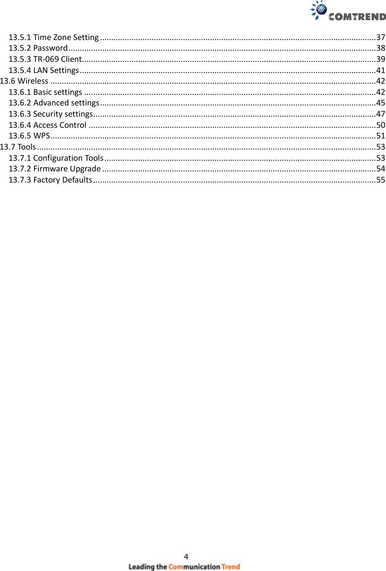
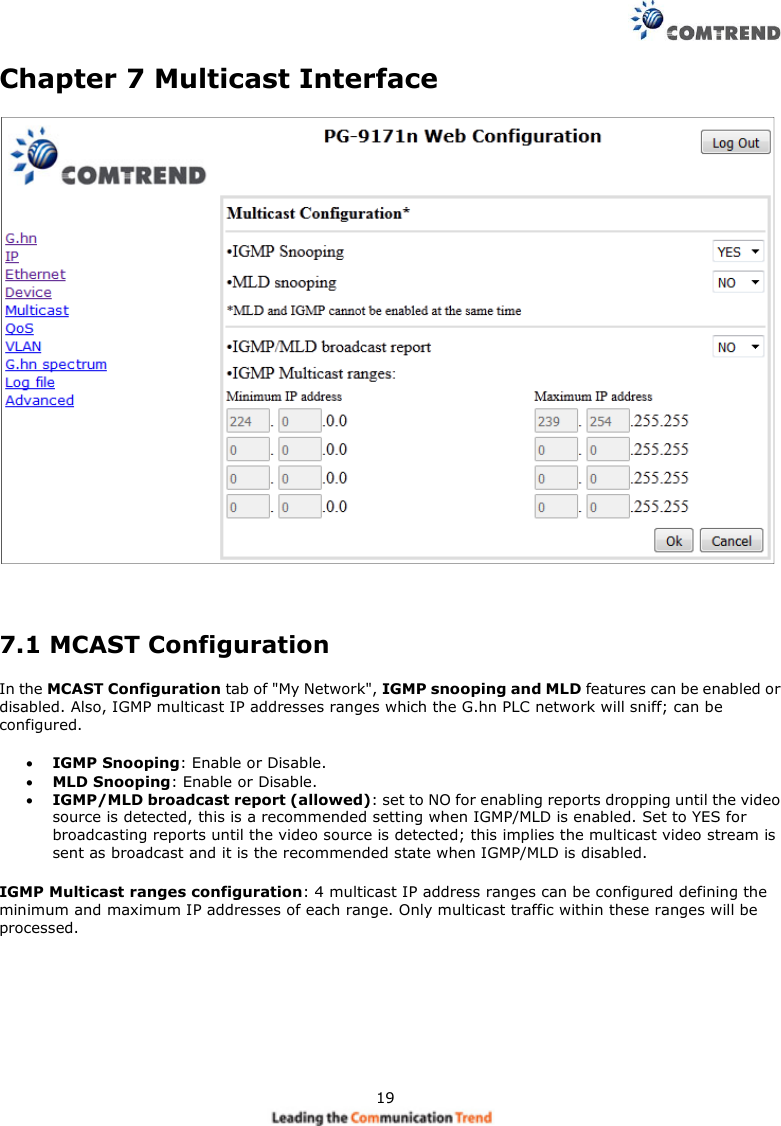
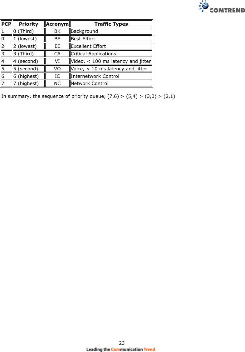
![22Example 1If QoS criterion: 802.1p, all other options are grayed out, and follow the QoS rules below.According to G.9960 specs, the priority mapping recommended by [IEEE 802.1D] subclause 7.7.3 ispresented in Table III.1. for four priority queues.](https://usermanual.wiki/Comtrend/PG9171N/User-Guide-2879470-Page-23.png)
![2913.1 Windows 7 IP address setup1. Click the Start button and select Control Panel. Double click Network and Internet and click Networkand Sharing Center, the Network and Sharing Center window will appear.2. Click Change adapter settings and right click on the Local Area Connection icon and select Properties.The Local Area Connection window will appear.3. Check your list of Network Components. You should see Internet Protocol Version 4 (TCP/IPv4) on yourlist. Select it and click the Properties button.4. In the Internet Protocol Version 4 (TCP/IPv4) Properties window, select ‘Use the following IP address’,then input the following settings in their respective fields:IP address: 192.168.0.2Subnet Mask: 255.255.255.05. Click OK to confirm the setting.已註解[Trevor1]:Is this ok?](https://usermanual.wiki/Comtrend/PG9171N/User-Guide-2879470-Page-30.png)
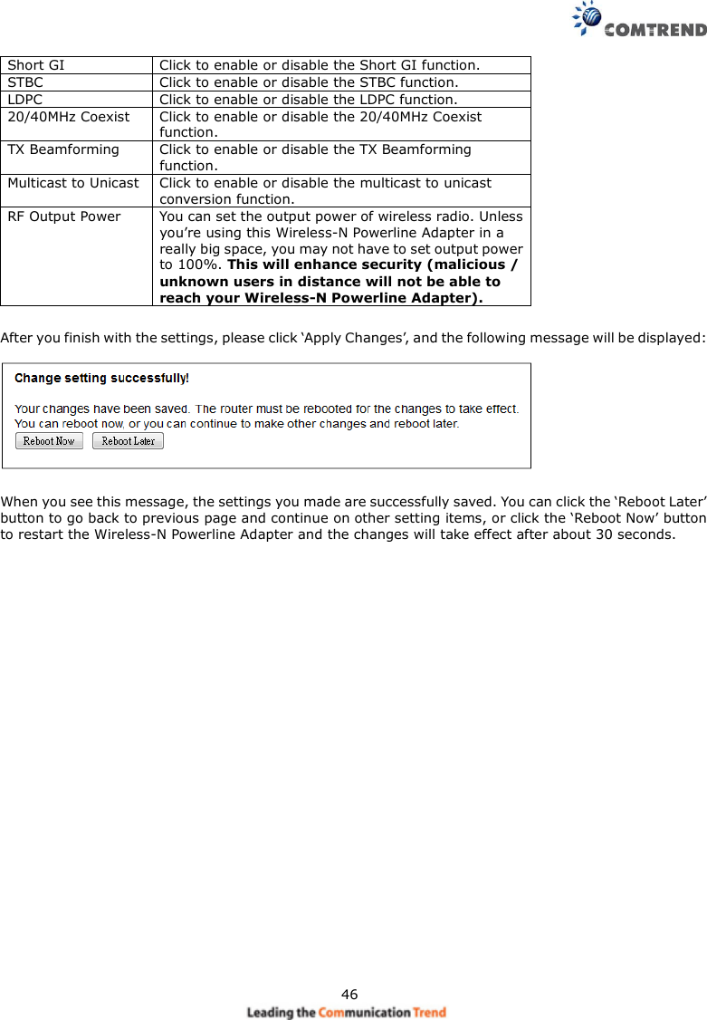
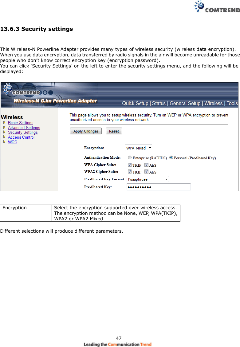
![4813.6.3.1 Disable SecurityWhen you select ‘Disable’, wireless encryption for the network is disabled.13.6.3.2 WEPWEP (Wired Equivalent Privacy) is a common encryption mode, it’s safe enough for home and personal use.But if you need higher level of security, please consider using WPA encryption (see next Section).However, some wireless clients don’t support WPA, but only support WEP, so WEP is still a good choice foryou if you have such kind of client in your network environment.When you select ‘WEP’ as the encryption type, the following will be displayed:802.1xAuthenticationWhile WEP Encryption is selected.Click the check box to enable the IEEE 802.1xauthentication function.AuthenticationKey Length There are two types of WEP key length: 64-bit and128-bit. Using ‘128-bit’ is safer than ’64-bit’, but willreduce some data transfer performance.已註解 [Trevor2]: Please provide a description](https://usermanual.wiki/Comtrend/PG9171N/User-Guide-2879470-Page-49.png)
![49Key Format There are two types of key format: ASCII and Hex. Whenyou select a key format, the number of characters of thekey will be displayed. For example, if you select ’64-bit’ askey length, and ‘Hex’ as key format, you’ll see themessage at the right of ‘Key Format’ is ‘Hex (10characters), which means the length of WEP key is 10characters.13.6.3.3 WPA/WPA2/WPA-MixWPA/WPA2/WPA-Mix are the safest encryption methods currently, and it’s recommended to use one ofthese encryption methods to ensure the safety of your data.In our example below we select ‘WPA-Mix’ as the encryption type. The following will be displayed:WPA AuthenticationModeClick to select the WPA-Mixed Authentication Mode withEnterprise(RADIUS) or Personal (Pre-Shared Key).WPA/WPA2 CipherSuiteThere are two type of Cipher :TKIP and AESPre-shared KeyFormatPlease select the format of pre-shared key here, availableoptions are ‘Passphrase’ (8 to 63 alphanumericalcharacters) and ‘Hex (64 hexadecimal characters – 0 to 9and a to f).Pre-shared Key Please input pre-shared key according to the key formatyou selected here. For security reasons, don’t use simplewords).已註解[Trevor3]:Please add to the description](https://usermanual.wiki/Comtrend/PG9171N/User-Guide-2879470-Page-50.png)