Comtrend PG9171N Powerline Ethernet + WiFi Adapter User Manual UM PG 9171n A2 0 20160103
Comtrend Corporation Powerline Ethernet + WiFi Adapter UM PG 9171n A2 0 20160103
Comtrend >
Users Manual
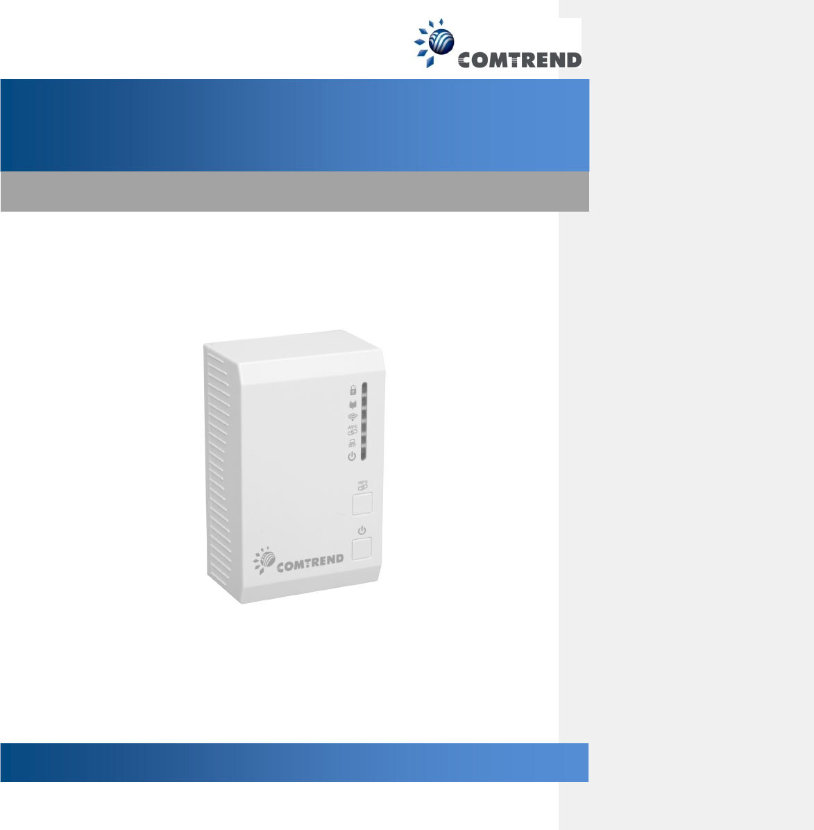
PowerGrid-9171n
Powerline Ethernet Adapter
User Manual
261
072
-
035
Version A2.0, November 3, 2015
1
Preface
This manual provides information related to the installation and operation of this device. The individual
reading this manual is presumed to have a basic understanding of telecommunications terminology and
concepts.
If you find the product to be inoperable or malfunctioning, please contact technical support for immediate
service by email at INT-support@comtrend.com
For product update, new product release, manual revision, or software upgrades, please visit our website
at http://www.comtrend.com
Important Safety Instructions
With reference to unpacking, installation, use, and maintenance of your electronic device, the following
basic guidelines are recommended:
Do not use or install this product near water, to avoid fire or shock hazard. For example, near a
bathtub, kitchen sink or laundry tub, or near a swimming pool. Also, do not expose the equipment
to rain or damp areas (e.g. a wet basement).
To safeguard the equipment against overheating, make sure that all openings in the unit that offer
exposure to air are not blocked.
Avoid using a telephone (other than a cordless type) during an electrical storm. There may be a
remote risk of electric shock from lightening. Also, do not use the telephone to report a gas leak
in the vicinity of the leak.
WARNING
Disconnect the Ethernet Adapter from the power source before servicing.
Copyright
Copyright©2015 Comtrend Corporation. All rights reserved. The information contained herein is
proprietary to Comtrend Corporation. No part of this document may be translated, transcribed,
reproduced, in any form, or by any means without prior written consent of Comtrend Corporation.
This program is free software: you can redistribute it and/or modify it under the terms of the GNU General
Public License as published by the Free Software Foundation, either version 3 of the License, or (at your
option) any later version.
This program is distributed in the hope that it will be useful, but WITHOUT ANY WARRANTY; without even
the implied warranty of MERCHANTABILITY or FITNESS FOR A PARTICULAR PURPOSE. See the GNU
General Public License for more details.
You should have received a copy of the GNU General Public License along with this program. If not, see
http://www.gnu.org/licenses/
NOTE: This document is subject to change without notice.
2
Protect Our Environment
This symbol indicates that when the equipment has reached the end of its useful life, it must be
taken to a recycling centre and processed separate from domestic waste.
The cardboard box, the plastic contained in the packaging, and the parts that make up this
Ethernet Adapter can be recycled in accordance with regionally established regulations.
Never dispose of this electronic equipment along with your household waste; you may be
subject to penalties or sanctions under the law. Instead, please be responsible and ask for
disposal instructions from your local government.
FCC
Federal Communication Commission Interference Statement
This equipment has been tested and found to comply with the limits for a Class B digital device, pursuant to Part 15 of the FCC Rules.
These limits are designed to provide reasonable protection against harmful interference in a residential installation. This equipment
generates, uses, and can radiate radio frequency energy and, if not installed and used in accordance with the instructions, may cause
harmful interference to radio communications. However, there is no guarantee that interference will not occur in a particular
installation. If this equipment does cause harmful interference to radio or television reception, which can be determined by turning the
equipment off and on, the user is encouraged to try to correct the interference by one or more of the following measures:
• Reorient or relocate the receiving antenna.
• Increase the separation between the equipment and receiver.
• Connect the equipment into an outlet on a circuit different from that to which the receiver is connected.
• Consult the dealer or an experienced radio/TV technician for help.
FCC Caution:
This device complies with Part 15 of the FCC Rules. Operation is subject to the following two conditions: (1) This device may not
cause harmful interference, and (2) this device must accept any interference received, including interference that may cause
undesired operation.
Non-modification Statement:
Changes or modifications not expressly approved by the party responsible for compliance could void the user's authority to operate
the equipment.
FCC Radiation Exposure Statement:
This equipment complies with FCC radiation exposure limits set forth for an uncontrolled environment. This equipment should be
installed and operated with minimum distance 20cm between the radiator & your body.

3
Table of Contents
Chapter 1 Product Information............................................................................................................................5
1.1 Front Panel and LED indicators ..................................................................................................................5
1.2 Bottom Panel .............................................................................................................................................6
1.3 How to understand the COVERAGE LED colors .........................................................................................7
1.4 Point-to-Point Network..............................................................................................................................8
1.5 Point to Multipoint Network .....................................................................................................................9
Chapter 2 Log In Procedure ...............................................................................................................................10
2.1 Configure STATIC IP MODE.......................................................................................................................10
2.2 Logging In.................................................................................................................................................11
Chapter 3 G.hn Interface ...................................................................................................................................12
3.1 Basic Configuration ..................................................................................................................................13
3.2 NDIM Configuration.................................................................................................................................13
3.3 Encryption Configuration via WEB UI ......................................................................................................13
Chapter 4 IP Interface ........................................................................................................................................14
4.1 IP config ...................................................................................................................................................15
Chapter 5 Ethernet Interface .............................................................................................................................16
Chapter 6 Device Interface ................................................................................................................................17
6.1 Hardware information .............................................................................................................................17
6.2 Software information...............................................................................................................................18
6.3 Security ....................................................................................................................................................18
6.4 SW update................................................................................................................................................18
Chapter 7 Multicast Interface............................................................................................................................19
7.1 MCAST Configuration...............................................................................................................................19
Chapter 8 QoS menu..........................................................................................................................................20
8.1 QoS Configuration....................................................................................................................................21
Chapter 9 VLAN Interface ..................................................................................................................................24
9.1 VLAN Configuration .................................................................................................................................24
Chapter 10 G.hn spectrum Interface .................................................................................................................25
10.1 Notches ..................................................................................................................................................25
Chapter 11 Log file Interface .............................................................................................................................26
11.1 Log File ...................................................................................................................................................26
Chapter 12 Advanced Interface .........................................................................................................................27
Chapter 13 Connecting to PG-9171nWireless-N Powerline Adapter by web browser .....................................28
13.1 Windows 7 IP address setup..................................................................................................................29
13.2 Connecting to Web Management Interface ..........................................................................................30
13.3 Quick Setup............................................................................................................................................31
13.3.1 LAN Settings....................................................................................................................................31
13.3.2 Wireless Settings.............................................................................................................................32
13.3.3 Security Settings..............................................................................................................................33
13.4 Status .....................................................................................................................................................34
13.4.1 Device Status ..................................................................................................................................34
13.4.2 System Log ......................................................................................................................................35
13.4.3 Statistics..........................................................................................................................................36
13.5 General Setup .....................................................................................................................................37

4
13.5.1 Time Zone Setting ...........................................................................................................................37
13.5.2 Password.........................................................................................................................................38
13.5.3 TR-069 Client...................................................................................................................................39
13.5.4 LAN Settings....................................................................................................................................41
13.6 Wireless .................................................................................................................................................42
13.6.1 Basic settings ..................................................................................................................................42
13.6.2 Advanced settings...........................................................................................................................45
13.6.3 Security settings..............................................................................................................................47
13.6.4 Access Control ................................................................................................................................50
13.6.5 WPS.................................................................................................................................................51
13.7 Tools .......................................................................................................................................................53
13.7.1 Configuration Tools.........................................................................................................................53
13.7.2 Firmware Upgrade ..........................................................................................................................54
13.7.3 Factory Defaults..............................................................................................................................55
5
Chapter 1 Product Information
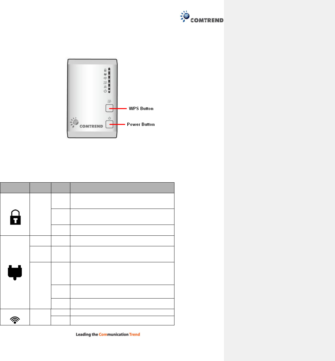
1.1 Front Panel and LED indicators
WPS Button: Press for 2 – 10 seconds to start the WPS function. Press for over 10 seconds to reset to
factory defaults.
Power Button: Push once to power up the PG-9171n
Push once to power down the PG-9171n
LED COLOR MODE Description
Security
Green
On Node is secure (it has either received or
generated network keys)
Off
Node is not secure, it has neither received nor
generated network key parameters (domain
name
and encryption key)
Blink Node is in configuration mode (able to
exchange network keys)
COVERAGE
Green On The current connection (estimated
throughput
) is greater than 40 Mbps
Orange On
The current connection (estimated
throughput) is greater than 20 Mbps and less
than 40 Mbps
Red
On
The current connection (estimated
throughput) is between 1 and 20 Mbps per
second)
Off No PLC connection exists
Blink Adapter in power saving mode (blinks twice
every 5 seconds)
WLAN
Green
Off WLAN is off
Blink Wireless is activity (tx/rx data and message)
6
WPS
Green
Off WPS function is disabled or there is no activity
Blink There is activity occurring
Ethernet
Green
On LAN connection established
Off LAN connection is not established
Blink Data transmitting/receiving
Power
Green
On The device is powered up
Off The device is powered down
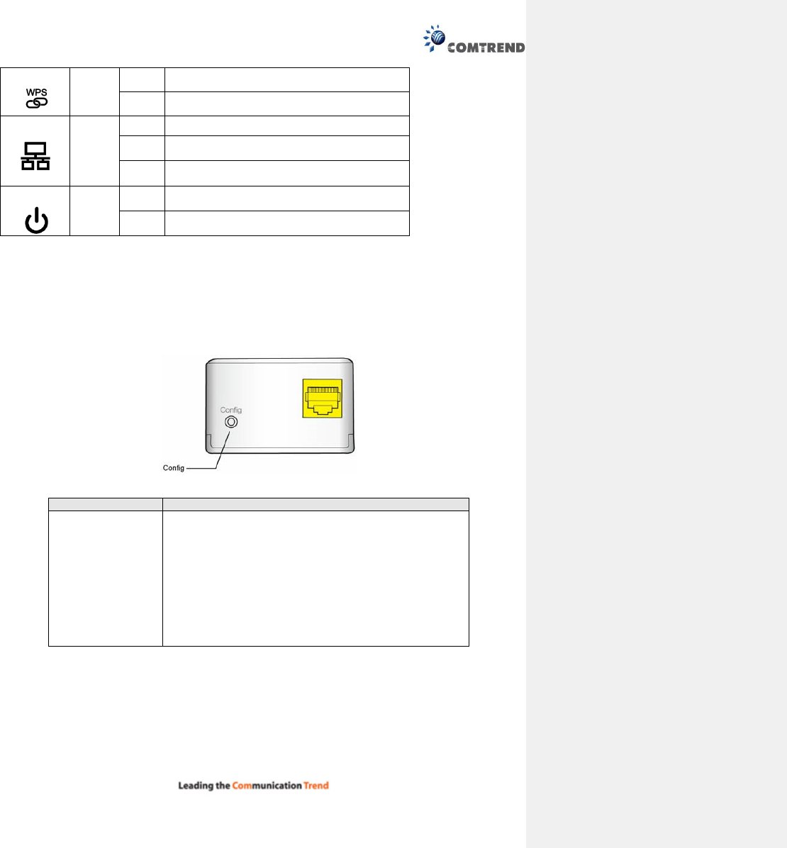
1.2 Bottom Panel
Item Name Description
Config
Press more than 2 seconds (“Security” LED starts slow
blinking) and released: the “One Button Security
Setup” (OBUS) procedure is started and configuration
period is open.
Press more than 5 seconds (“Security” LED starts quick
blinking) and released: security settings are set to
default values.
Press more than 10 seconds (“Security” LED switches
off) and released: a factory reset is performed.
7
1.3 How to understand the COVERAGE LED colors
The COVERAGE LED displays quality of the network and provides important information that will
provide solutions to common questions, such as why a High Definition (HD) movie is not showing or
shows with pixels. The COVERAGE LED indicator will vary its color depending on the estimated speed of
the Powerline connection. The speed is measured in Megabits Per Second (Mbps).
C
olo
r
I
n
fo
r
ma
t
io
n
RED
The current connection has standard quality, normal Internet
activities ex. 20Mbps are possible but the Powerline is unable to
transmit either a Standard Movie or High Definition (HD) Movie.
ORANGE
The current connection has good quality and Internet activities
ex. greater than 20Mbps and less than 40Mbps to transmit
Standard Movie and HD Movie.
GREEN
The current connection has excellent quality and Internet
activities ex. greater than
40Mbps to transmit multiple Standard
Movies and HD Movies.
8
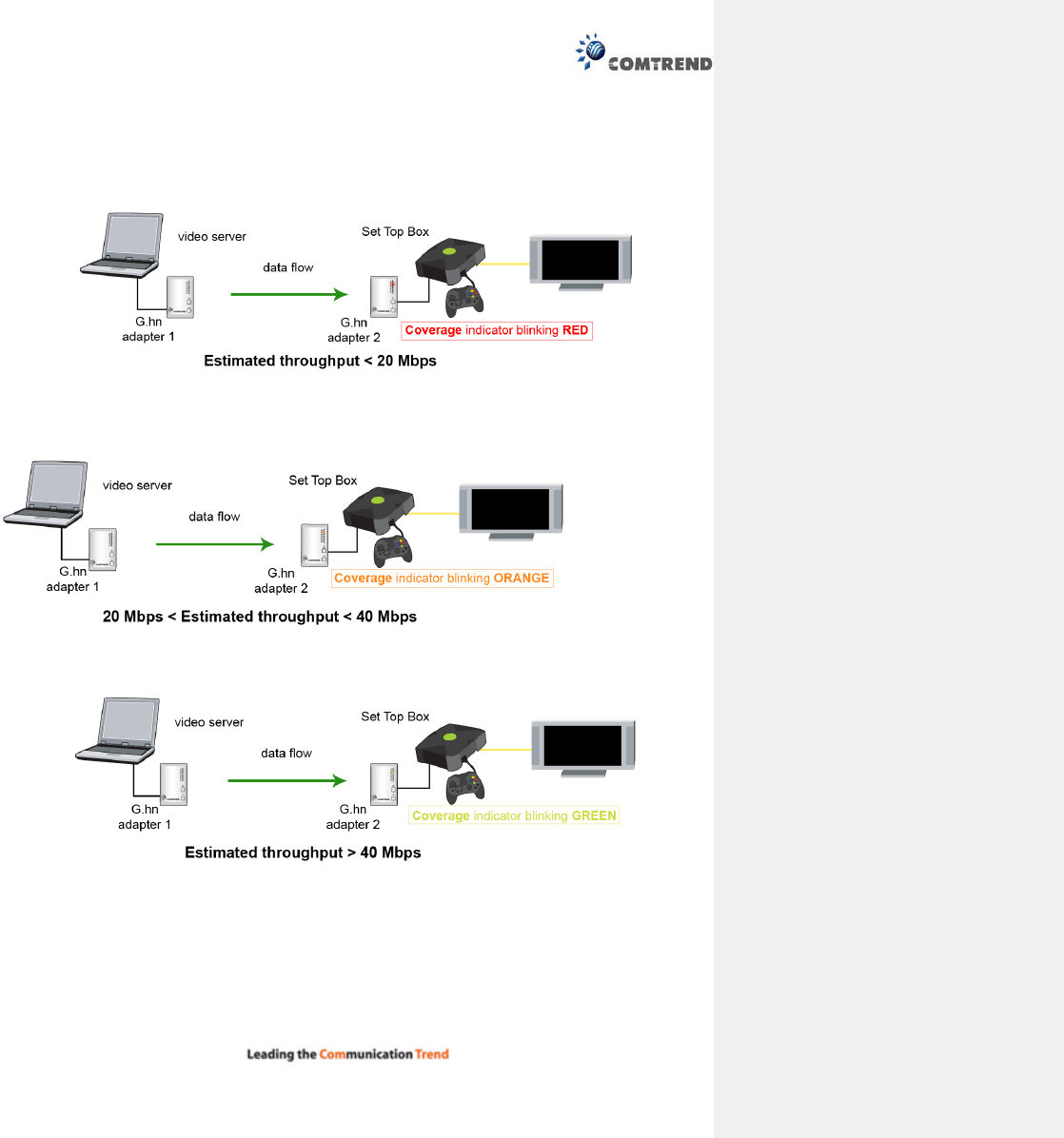
1.4 Point-to-Point Network
CASE 1: Estimated throughput is less than 20 Mbps. The PLC channel is not able to transmit an
SDTV channel. The COVERAGE LED will be RED as shown in the following figure:
CASE 2: Estimated throughput is greater than 20 Mbps but less than 40 Mbps. The PLC channel is
able to transmit an SDTV channel, but not two SDTV channels simultaneously or one HDTV channel.
The COVERAGE LED will be ORANGE as shown in the following figure:
CASE 3: Estimated throughput is greater than 10 Mbps. The PLC channel is able to play at least two
SDTV channels or 1 HDTV. The COVERAGE LED will be GREEN as shown here:
9
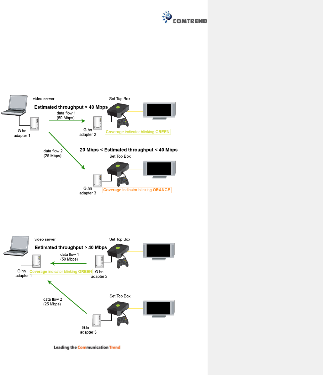
1.5 Point to Multipoint Network
In the case where the PLC network is composed of three or more adapters, similar situations could arise as
with a point-to-point network.
CASE 1: The COVERAGE LED in G.hn adapter 2 and G.hn adapter 3 will show the estimated level of
the PLC link receiving from G.hn adapter 1.
CASE 2: The COVERAGE LED in G.hn adapter 1 will show the estimated level of the PLC link from
which it is receiving the most amount of traffic at any given time. For example, if G.hn adapter 1 is
receiving traffic at 50Mbps from G.hn adapter 2 and is receiving 25Mbps from G.hn adapter 3, the
COVERAGE LED will show the level with reference to the G.hn adapter 2 link, as shown in the following
figure.
10
Chapter 2 Log In Procedure
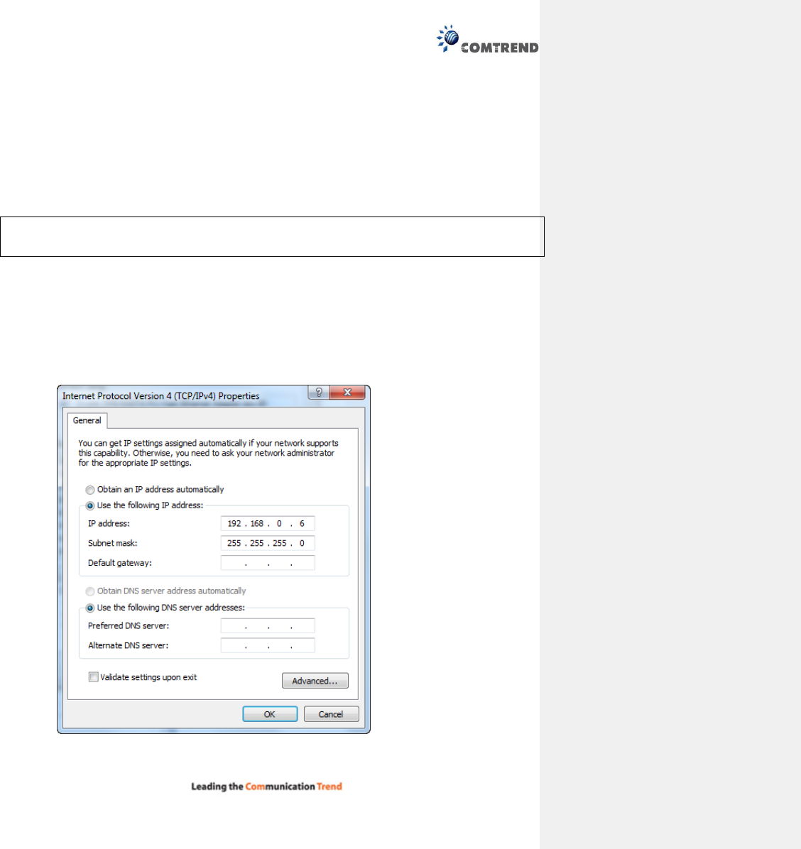
2.1 Configure STATIC IP MODE
In static IP mode, you assign IP settings to your PC manually.
Follow these steps to configure your PC IP address to use subnet 192.168.0.x.
NOTE: The following procedure assumes you are running Windows XP. However, the general steps
involved are similar for most operating systems (OS). Check your OS support documentation
for further details.
STEP 1: From the Network Connections window, open Local Area Connection (You may also access this
screen by double-clicking the Local Area Connection icon on your taskbar). Click the
Properties button.
STEP 2: Select Internet Protocol (TCP/IP) and click the Properties button.
STEP 3: Change the IP address to the domain of 192.168.0.x (5<x<255) with subnet mask of
255.255.255.0. The screen should now display as below.
STEP 4: Click OK to submit these settings.
11
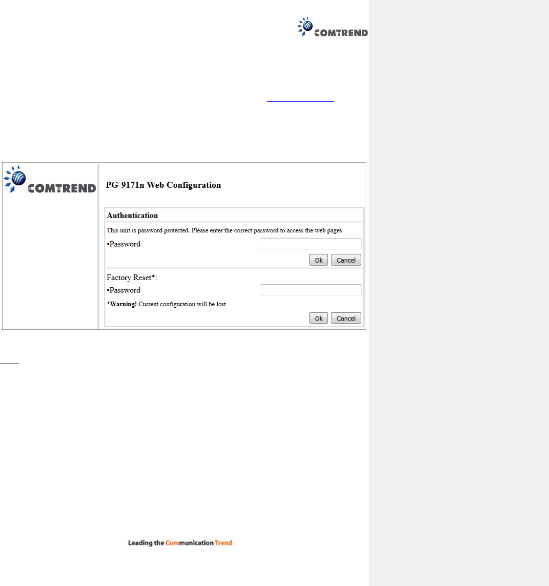
2.2 Logging In
Perform the following steps to login to the web user interface.
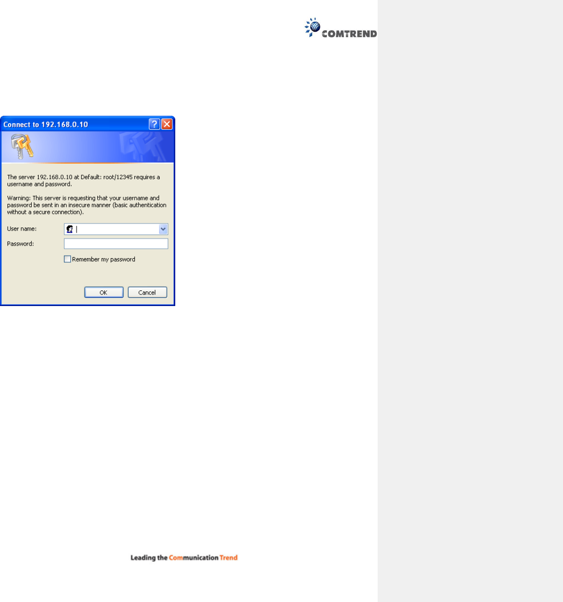
STEP 1: Start the Internet browser and enter the default IP address for the device in the Web address
field. For example, if the default IP address is 192.168.0.5, type http://192.168.0.5
STEP 2: A dialog box will appear, such as the one below. Input the default Authentication Password.
Authentication Password: admin
Click OK to continue.
Note:
The Factory Reset password is: betera
12
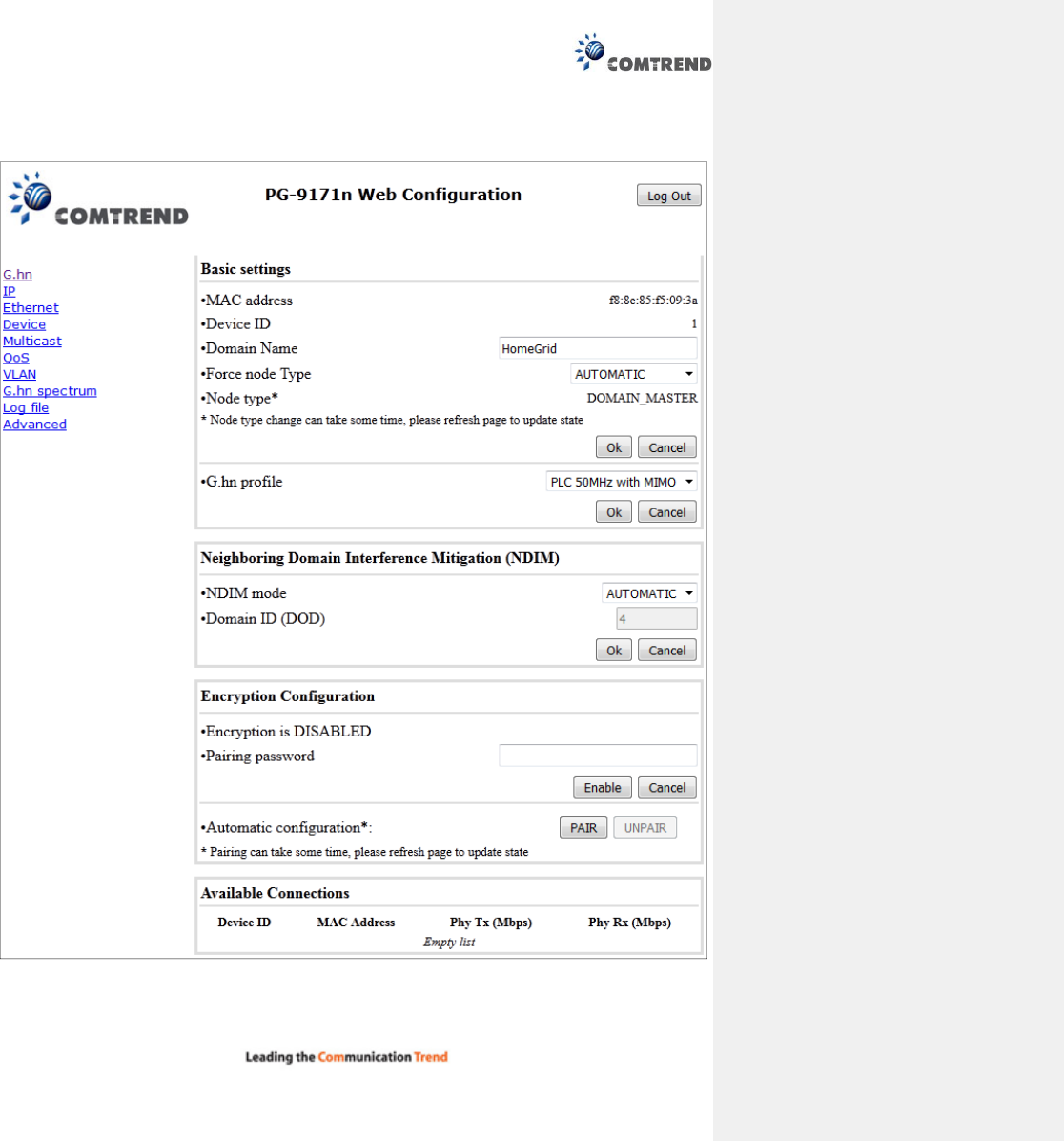
Chapter 3 G.hn Interface

13
3.1 Basic Configuration
MAC Address Displays the MAC address of the device.
Device ID Device ID of this node.
Domain Name string of all nodes in the network.
Force node Type force the modem to have a particular role (END POINT or DOMAIN MASTER)
G.hn profile of all nodes in the network: selecting which G.hn profile must be applied to the
network (PLC 50MHz, PLC 50MHz with MIMO, PLC 100MHz, COAX 100MHz and PHONE 100MHz).
3.2 NDIM Configuration
NDIM mode set to Automatic for enabling automatic DOD selection functionality and set to Manual
for manual configuration of DOD.
Domain ID (DOD) manually set the DOD number from 1 to 15 to use a different preamble seed
than the default 0.
3.3 Encryption Configuration via WEB UI
Pairing Password used for authentication. Write a custom password to manually create a secure
domain.
Available Connections
In this tab table, all the available G.hn connections are presented. Remote node DID and MAC
address, transmission and reception physical speeds.
14
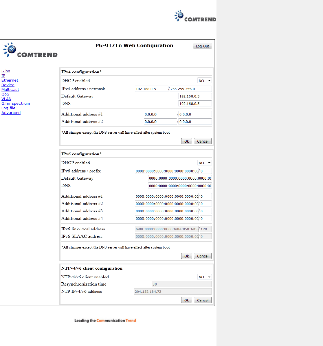
Chapter 4 IP Interface
15
4.1 IP config
In the IP configuration tab of one G.hn node, the IPv4 and IPv6 settings can be read and changed.
IPv4 subsection:
DHCPv4 enabled: in the case of choosing ”NO" IP configuration in the following parameters, the
IPv4 Address, Subnet Mask, Default Gateway and DNS should be configured; fill these fields in. In
the case of choosing “YES” they will be filled automatically when configuration is received from the
DHCPv4 server.
IPv4 address/netmask: IPv4 address / netmask of this device.
Default Gateway: IPv4 gateway to connect the device to other LAN segments.
DNS: Domain Name Server IP (IPV4).
Additional address #1/2: additional fixed IPv4 addresses that will always be configured at boot
time.
IPv6 subsection:
DCHPv6 enabled: in the case of choosing ”NO" IP configuration in the following parameters, the
IPv6 Address, prefix, Default Gateway and DNS should be configured; fill these fields in. In the case
of choosing “YES” they will be filled automatically when configuration is received from the DHCPv6
server.
IPv6 Address / prefix: IPv6 address / prefix of the device to read the node's DHCPv6 address in
case the DHCPv6 is enabled.
Default Gateway: IPv6 gateway to connect the node to other LAN segments.
DNS: Domain Name Server IP (IPV6).
Additional address #1/2/3/4: additional fixed IPv6 addresses that will always be configured at
boot time.
IPv6 Link-Local Address: to read the node's Link Local address.
IPv6 SLAAC address: IPv6 address, automatically obtained by means of the SLAAC mechanism.
NTPv4/v6 subsection:
NTPv4/v6 client enabled: Enable/disable NTP client.
Resynchronization time: Configure re-synchronization interval time in minutes.
NTP IPv4/v6 address: Hostname or IP (IPv4 or IPv6) of NTP server.
16
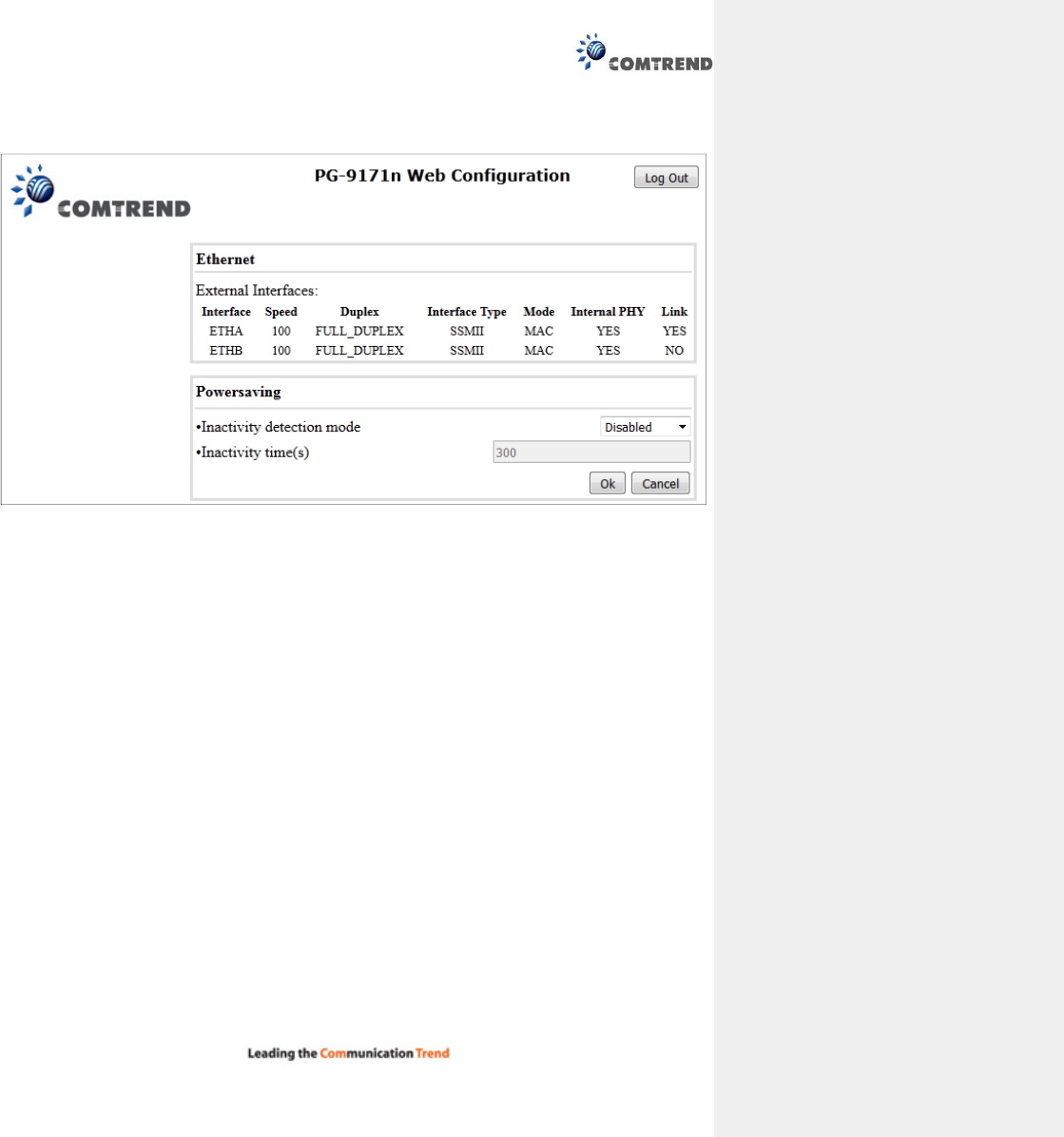
Chapter 5 Ethernet Interface
The Ethernet table shows the coverage & Info of the Ethernet interface; including Interface, Speed, Duplex,
Interface Type, Mode, Internal PHY & Link.
Powersaving
Ethernet powersaving can be disabled, enabled by Ethernet link or enabled by Ethernet activity; idle timer
can be configured as well.
17
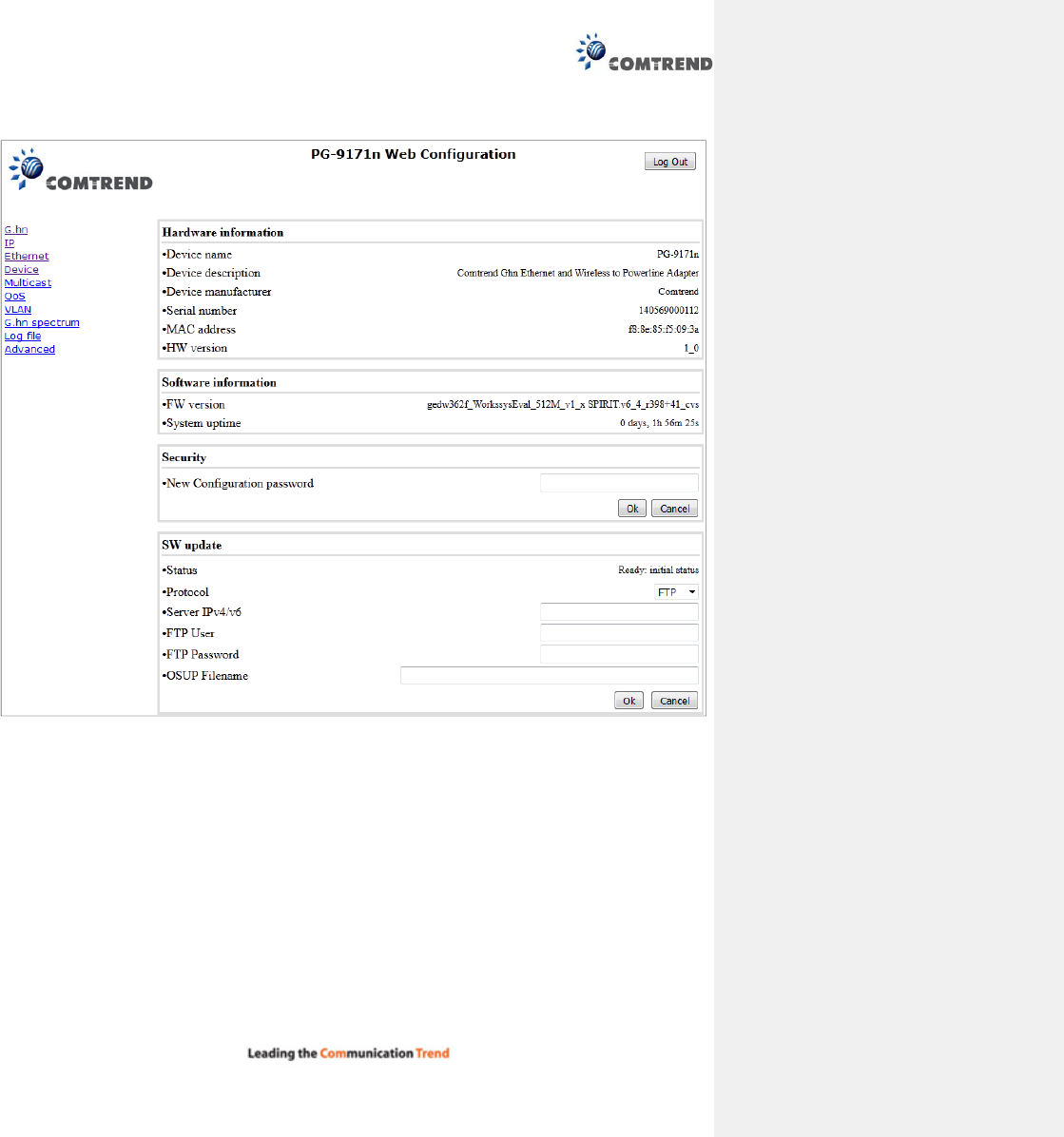
Chapter 6 Device Interface
6.1 Hardware information
In this tab, basic information such as MAC Address and Serial Number of the selected node is shown.

18
6.2 Software information
Shows the FW version and system uptime.
6.3 Security
The nodes in the network: to change the configuration password string from the default ("admin") to
another; decided by the user.
6.4 SW update
Current loaded firmware version is shown. Any flash section can be upgraded; the first flash section should
be selected and after clicking on the "OK" button the corresponding file should be chosen. Usually, a reboot
should be performed afterwards to make sure the changes are effective.
The protocol is by FTP client or TFTP client. L2 is proprietary and is reserved for future use.
19
Chapter 7 Multicast Interface
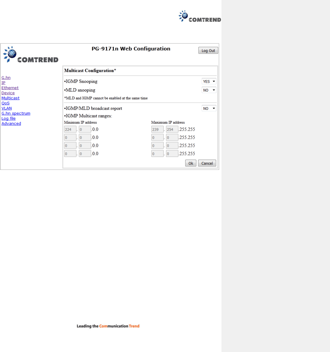
7.1 MCAST Configuration
In the MCAST Configuration tab of "My Network", IGMP snooping and MLD features can be enabled or
disabled. Also, IGMP multicast IP addresses ranges which the G.hn PLC network will sniff; can be
configured.
IGMP Snooping: Enable or Disable.
MLD Snooping: Enable or Disable.
IGMP/MLD broadcast report (allowed): set to NO for enabling reports dropping until the video
source is detected, this is a recommended setting when IGMP/MLD is enabled. Set to YES for
broadcasting reports until the video source is detected; this implies the multicast video stream is
sent as broadcast and it is the recommended state when IGMP/MLD is disabled.
IGMP Multicast ranges configuration: 4 multicast IP address ranges can be configured defining the
minimum and maximum IP addresses of each range. Only multicast traffic within these ranges will be
processed.
20
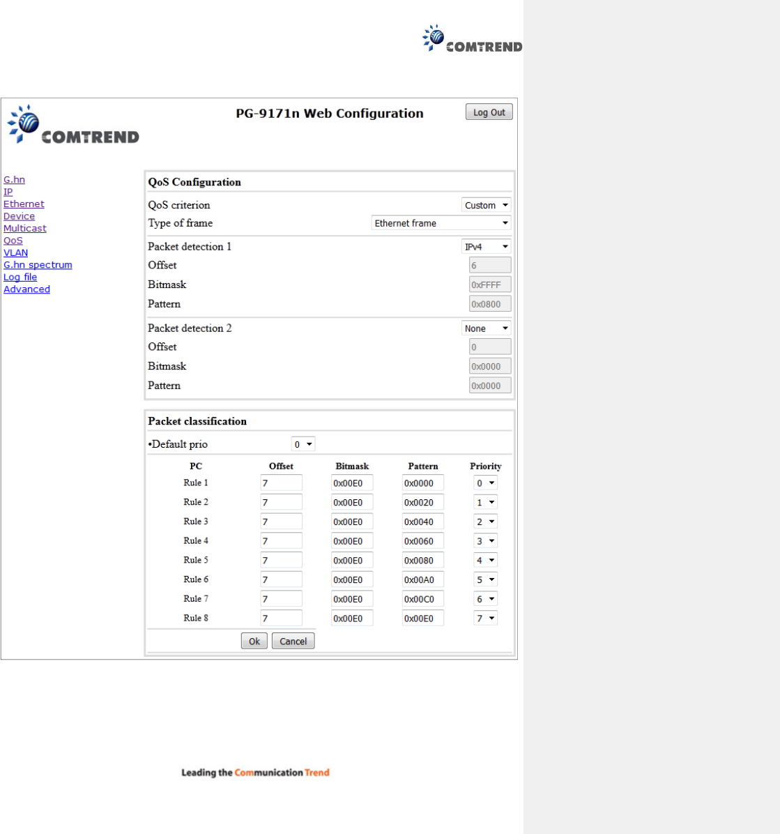
Chapter 8 QoS menu

21
8.1 QoS Configuration
In the QoS configuration tab, the packet classifier can be managed to define a QoS rule for incoming
Ethernet traffic, and assign a priority to be used in the G.hn network. Press the “Ok" button for loading the
newly configured settings:
QoS CRITERION: a general criterion can be chosen among "None" (no QoS), "Custom" and
"802.1p".
Type of Frame: with this parameter the type of Ethernet traffic being transmitted by the G.hn
network should be selected. Based on this parameter, the internal offsets in the system are
adjusted. In the QoS tab, Ethernet frame offsets should be set counting number as they appear
in the sniffer SW (for instance, the same field will be in a different position if normal Ethernet frames
or 802.1Q tagged frames exist).
Packet detection 1: first packet detection rule can be configured (offset, bitmask and pattern).
Packets which accomplish it will be sent to the classification module.
Packet detection 2: if second packet detection is also enabled, both, first and second detection
criteria must be accomplished to pass packets to the classification module.
Packet classification: up to 8 classification rules can be defined in this section for packets which
have previously been correctly detected. For 802.1p only priorities can be managed, offset, bitmask
and pattern are predefined to sniff the PCP field.
Default priority: select default priority; which will be applied to non classified incoming packets.
Priority 7 is the highest. Priority 0 is the lowest.
22
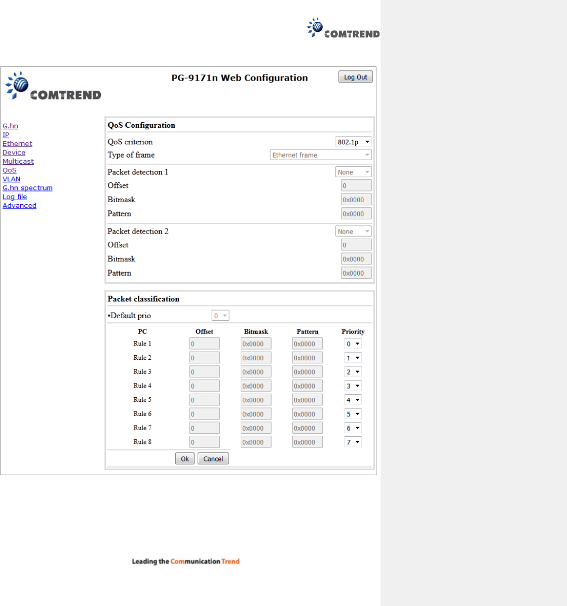
Example 1
If QoS criterion: 802.1p, all other options are grayed out, and follow the QoS rules below.
According to G.9960 specs, the priority mapping recommended by [IEEE 802.1D] subclause 7.7.3 is
presented in Table III.1. for four priority queues.
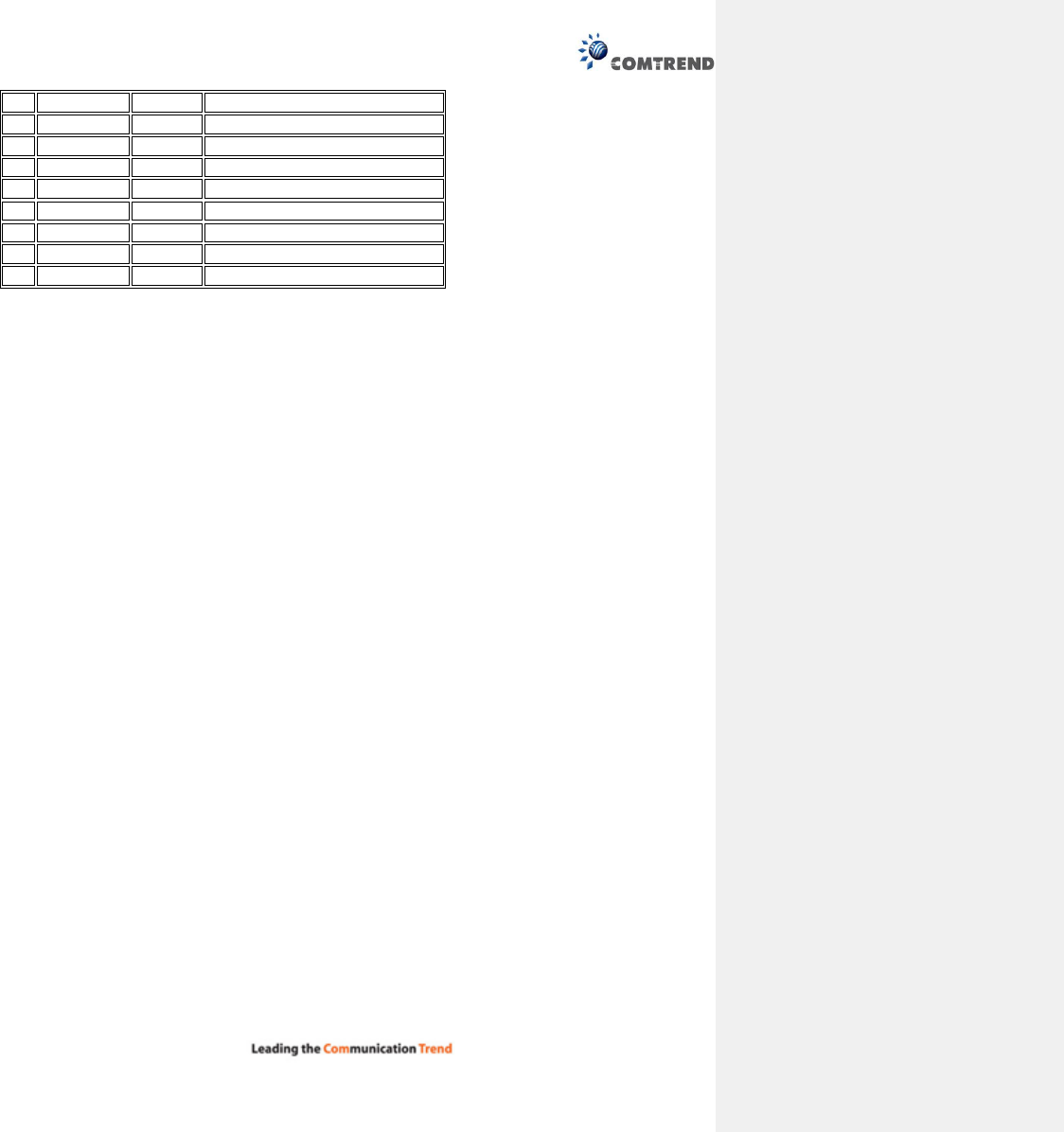
23
PCP
Priority
Acronym
Traffic Types
1 0 (Third) BK Background
0
1
(
lowest
)
BE
Best Effort
2
2
(lowest)
EE
Excellent Effort
3
3
(Third)
CA
Critical Applications
4
4
(second)
VI
Video, < 100 ms
latency
and
jitter
5 5 (second) VO Voice, < 10 ms latency and jitter
6
6
(highest)
IC
Internetwork Control
7 7 (highest) NC Network Control
In summary, the sequence of priority queue, (7,6) > (5,4) > (3,0) > (2,1)
24
Chapter 9 VLAN Interface
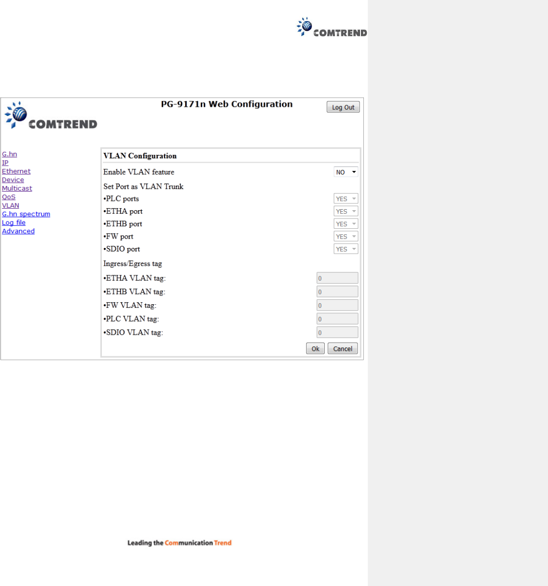
9.1 VLAN Configuration
In the VLAN Configuration tab of one G.hn node, a VLAN tag can be added or removed per interface. Also,
removing a tag at egress per interface can be also enabled or disabled:
Enable VLAN Configuration: Select No from the drop down menu to disable completely the VLAN
functionality, removing all tags.
Remove VLAN tag at egress: Select Yes from the drop down menu for the port that you want to
remove the VLAN tag from.
Ingress/Egress tag: A tag value (from 1 to 4095) per interface can be added in this section. Set
value to 0 for no tagging.
25
Chapter 10 G.hn spectrum Interface
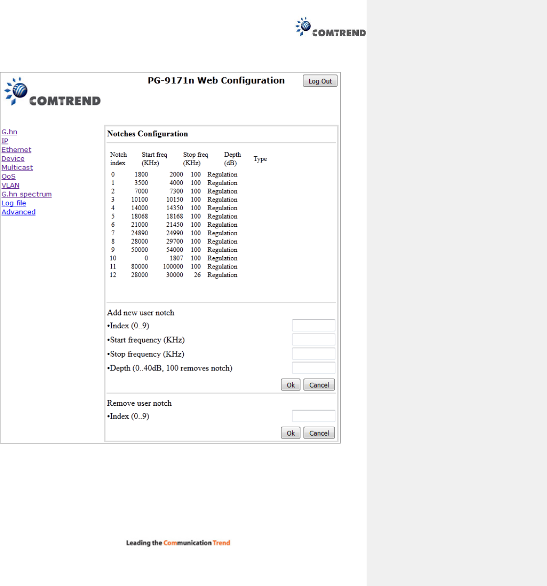
10.1 Notches
In this tab a table with all configured Notches of selected node will be shown. The table is composed of
next columns for every notch: Notch Number, Type of notch, Start Frequency (KHz), Stop Frequency (KHz),
Depth (in dB).
26
The first 22 notches (Regulation) are Read Only, RO, in the system and they can be neither removed nor
modified. The next 40 notches (Vendor) are defined by the vendor using SDK and they are also RO. The last
10 notches (User) are R/W and they can be added/removed by user using this tool.
To add new notches the user should fill the "Add a new User Notch" fields, setting Start and Stop
frequencies in KHz and depth in dB of notch and then press the "Ok" button. They will be added in first User
free position from number 0 to 9. (If successful, you can see a record in the Type column)
To remove a User Notch, the "Remove a User Notch" section should be used, setting notch number to be
removed from 0 to 9 and pressing the "Ok" button.
Chapter 11 Log file Interface
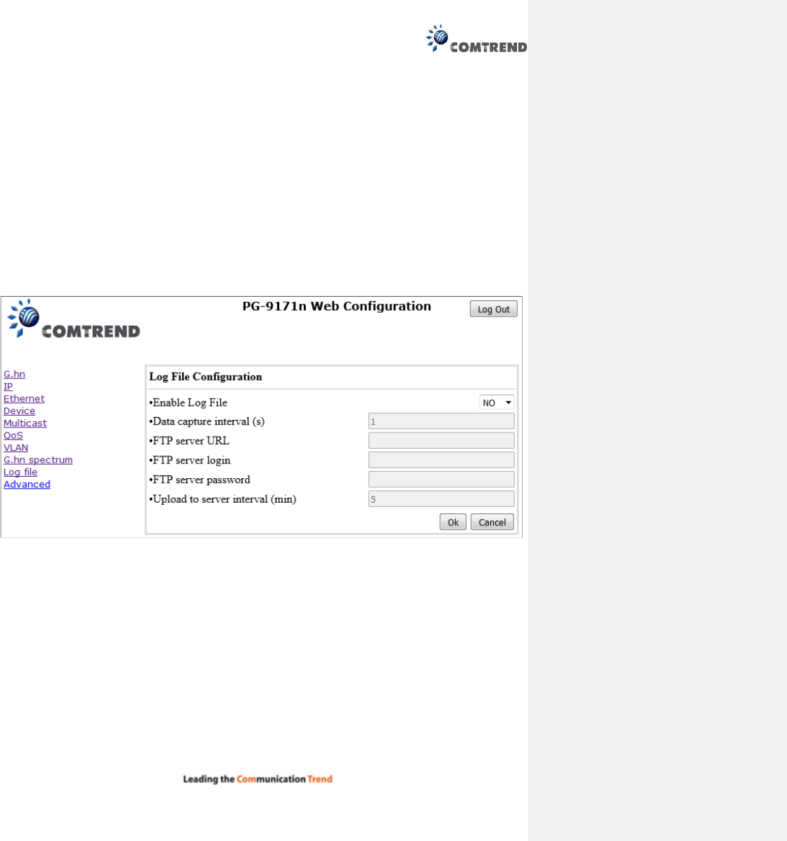
11.1 Log File
In the Log File configuration the following settings can be read, and changed by clicking on the
corresponding "OK" button for the selected node:
Enable Log File set to YES for enabling Log File functionality in the node and set to NO for disabling
it.
Data Capture Interval sets the interval of time in seconds to capture data.
FTP Server URL configures the url for the remote FTP server where the files will be uploaded.
FTP Server Login configures the user for the FTP server.
FTP Server Password configures the password for the FTP server.
Upload to Server Interval sets the interval of time in minutes to send the captured file to the
remote server.
27
Chapter 12 Advanced Interface
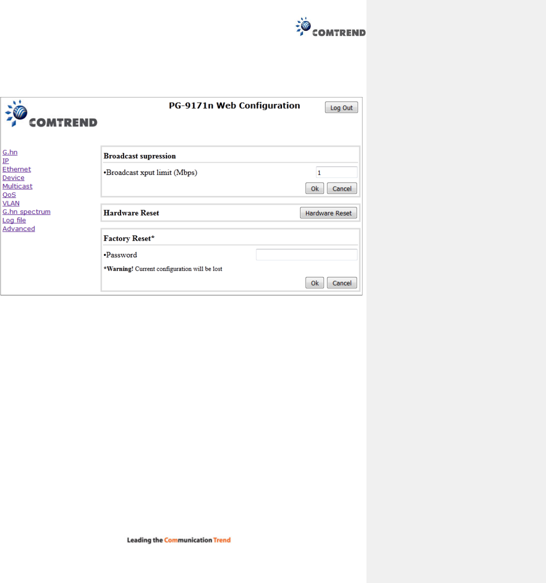
Broadcast suppression :In this tab the broadcast suppression feature can be managed. Broadcast traffic
higher than the selected value will be dropped.
Hardware Reset: Click on this button to perform a reboot in the node.
Factory Reset: Input the password: betera and click the OK button to perform a factory reset. The
current configuration will be lost.

28
Chapter 13 Connecting to PG-9171nWireless-N
Powerline Adapter by web browser
After the network connection is complete, the next step you should perform is to setup the Wireless-N
Powerline Adapter with proper network parameters, so it can work properly in your network environment.
Before you can connect to the Wireless-N Powerline Adapter and start configuration procedures, your
computer must be able to get an IP address automatically (use dynamic IP address). If it’s set to use static
IP address, or you’re unsure, please follow the instructions below to configure your computer to use
dynamic IP address. Windows 7 is used for reference; other operating systems might have slightly different
configuration options or interfaces.
29
13.1 Windows 7 IP address setup
1. Click the Start button and select Control Panel. Double click Network and Internet and click Network
and Sharing Center, the Network and Sharing Center window will appear.
2. Click Change adapter settings and right click on the Local Area Connection icon and select Properties.
The Local Area Connection window will appear.
3. Check your list of Network Components. You should see Internet Protocol Version 4 (TCP/IPv4) on your
list. Select it and click the Properties button.
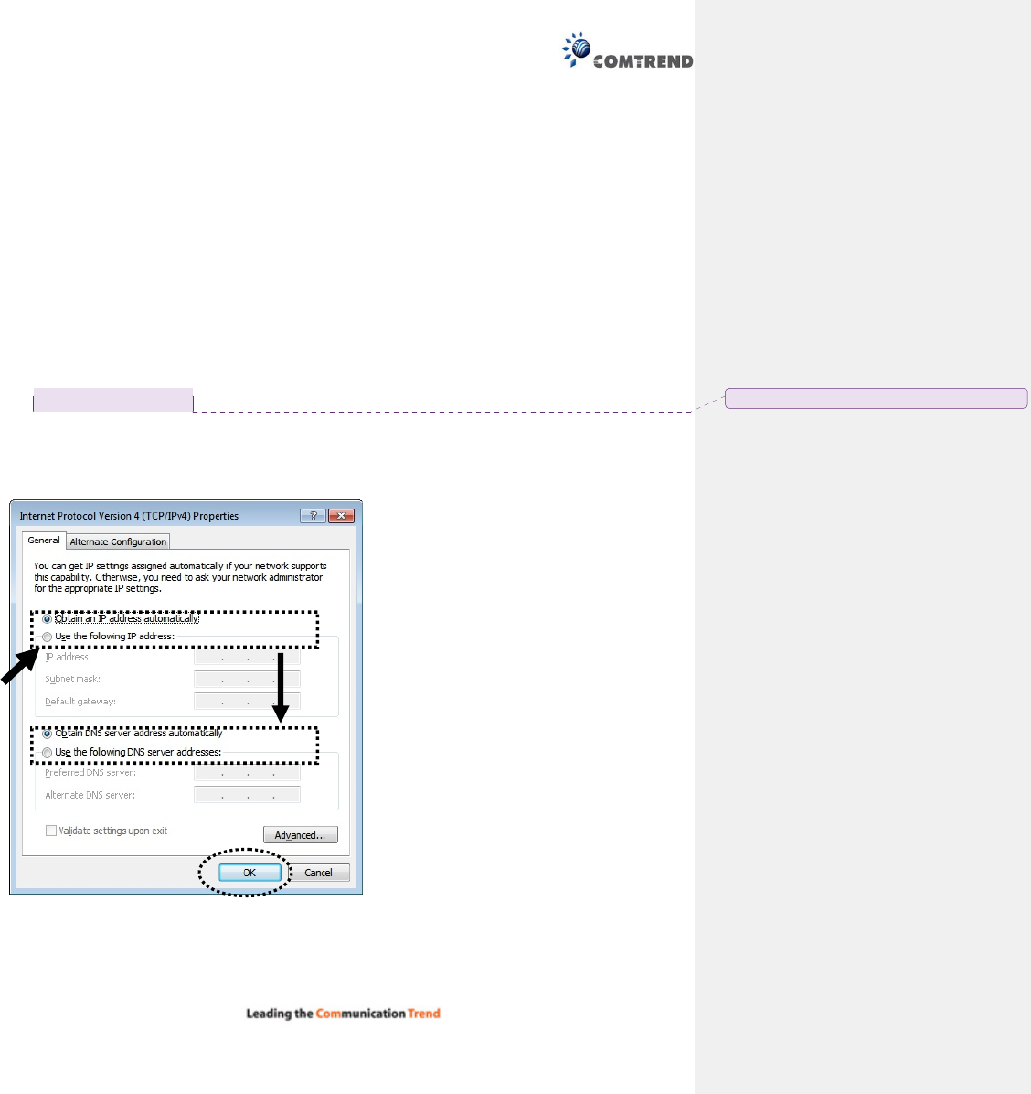
4. In the Internet Protocol Version 4 (TCP/IPv4) Properties window, select ‘Use the following IP address’,
then input the following settings in their respective fields:
IP address: 192.168.0.2
Subnet Mask: 255.255.255.0
5. Click OK to confirm the setting.
已註解
[Trevor1]:
Is this ok?
30
13.2 Connecting to Web Management Interface
All functions and settings of this Wireless-N Powerline Adapter must be configured via web management
interface. Please start your web browser, and input ‘192.168.0.10’ in the address bar, then press ‘Enter’
key. The following should be displayed:
Input the user name and password in the respective fields, default user name is ‘root’, and default
password is ‘12345’, then press the ‘OK’ button, and you can see the Quick Setup interface of this
Wireless-N Powerline Adapter.
31
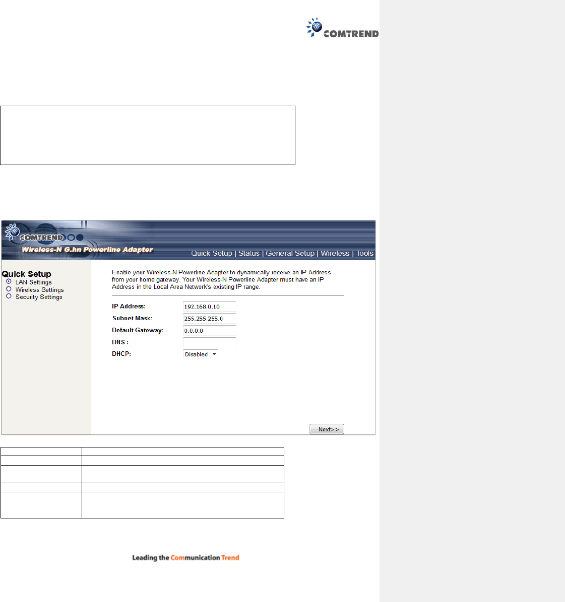
13.3 Quick Setup
After login, the Quick Setup screen will appear. It is the default screen when no connections exist. This
screen allows for the configuration of DSL settings and the IP configuration. It includes LAN, Wireless and
Security setup screens.
13.3.1 LAN Settings
Enable your Wireless-N Powerline Adapter to dynamically receive an IP Address from your home gateway.
Your Wireless-N Powerline Adapter must have an IP Address in the Local Area Network's existing IP range.
IP Address
The IP address for the
Wireless
-
N Powerline Adapter
.
Subnet Mask The Subnet Mask for the Wireless-N Powerline Adapter.
Default Gateway Specify the IP address of the default gateway of your
network here.
DNS
Input the IP address of the domain name server.
DHCP Disable or Enable DHCP client. If Enabled, IP Address,
Subnet Mask, Default Gateway and DNS will be
obtained by DHCP client automatically.
Click the Next button to continue.
NOTE: If you can’t see the web management interface, and you’re being
prompted to input user name and password again, it means you didn’t
input the username and password correctly. Please retype the user
name and password again. If you’re certain about the user name and
password you type are correct, please see section 1.2 to perform a
factory reset, to set the password back to default value.
32
13.3.2 Wireless Settings
This page is used to configure the parameters for the wireless connection of tablets, smart phones, and
laptops.
Click the Next button to continue.
Band Select the wireless band you wish to use. By selecting a
different band setting, you’ll be able to allow or deny the
wireless client of a certain band.
If you select 2.4GHz (B), 2.4GHz (N), or 2.4GHz (G), only
wireless clients using the wireless band you select (802.11b,
802.11 n, or 802.11g) will be able to connect to this
Wireless-N Powerline Adapter.
If you select 2.4GHz (B+G), then only wireless clients using
802.11b and 802.11g band will be able to connect to this
Wireless-N Powerline Adapter.
If you want to allow 802.11b, 802.11g, and 802.11 Draft-N
clients to connect to this Wireless-N Powerline Adapter, select
2.4GHz (B+G+N).
Mode PG-9171n only supports AP mode.
Network
Type
In Infrastructure Mode, wireless clients can access the other
networks (perhaps Internet) via this AP. For AP. Only
Infrastructure Mode is allowed here.
SSID Input the ESSID (the name used to identify this Wireless-N
Powerline Adapter) here. You can input up to 32
alphanumerical characters. PLEASE NOTE THAT THE ESSID IS
CASE SENSITIVE.
Channel
Width
Select wireless channel width (bandwidth taken by wireless
signals of this Wireless-N Powerline Adapter). It’s suggested
to select ‘Auto 20/40MHz’. Do not change to ’20 MHz’ unless
you know what it is.
33
Control
Sideband
Specify if the extension channel should be in the Upper or
Lower sideband.
Channel
Number
Select a channel number (“Auto” is recommended).
Please select a channel number you wish to use. If you know a
certain channel number is being used by other wireless access
points nearby, please refrain from using the same channel
number.
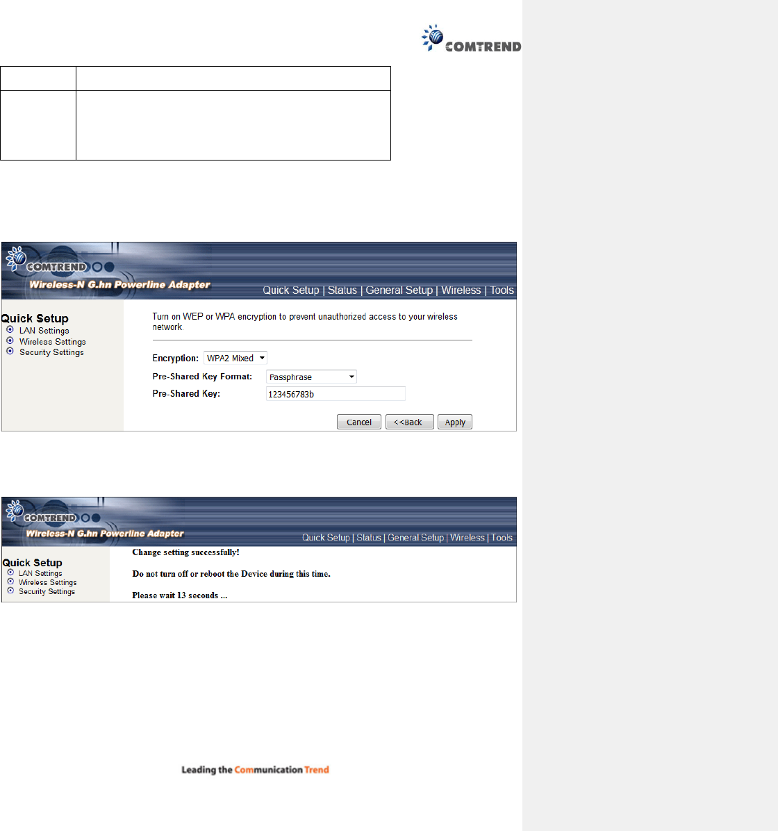
13.3.3 Security Settings
Turn on WEP or WPA encryption to prevent unauthorized access to your wireless network.
Select the Encryption method from the drop down menu. Then select and fill in the required parameters.
Click the Apply button to display the following.
Do not turn off or reboot the device during this time.
34
13.4 Status
13.4.1 Device Status
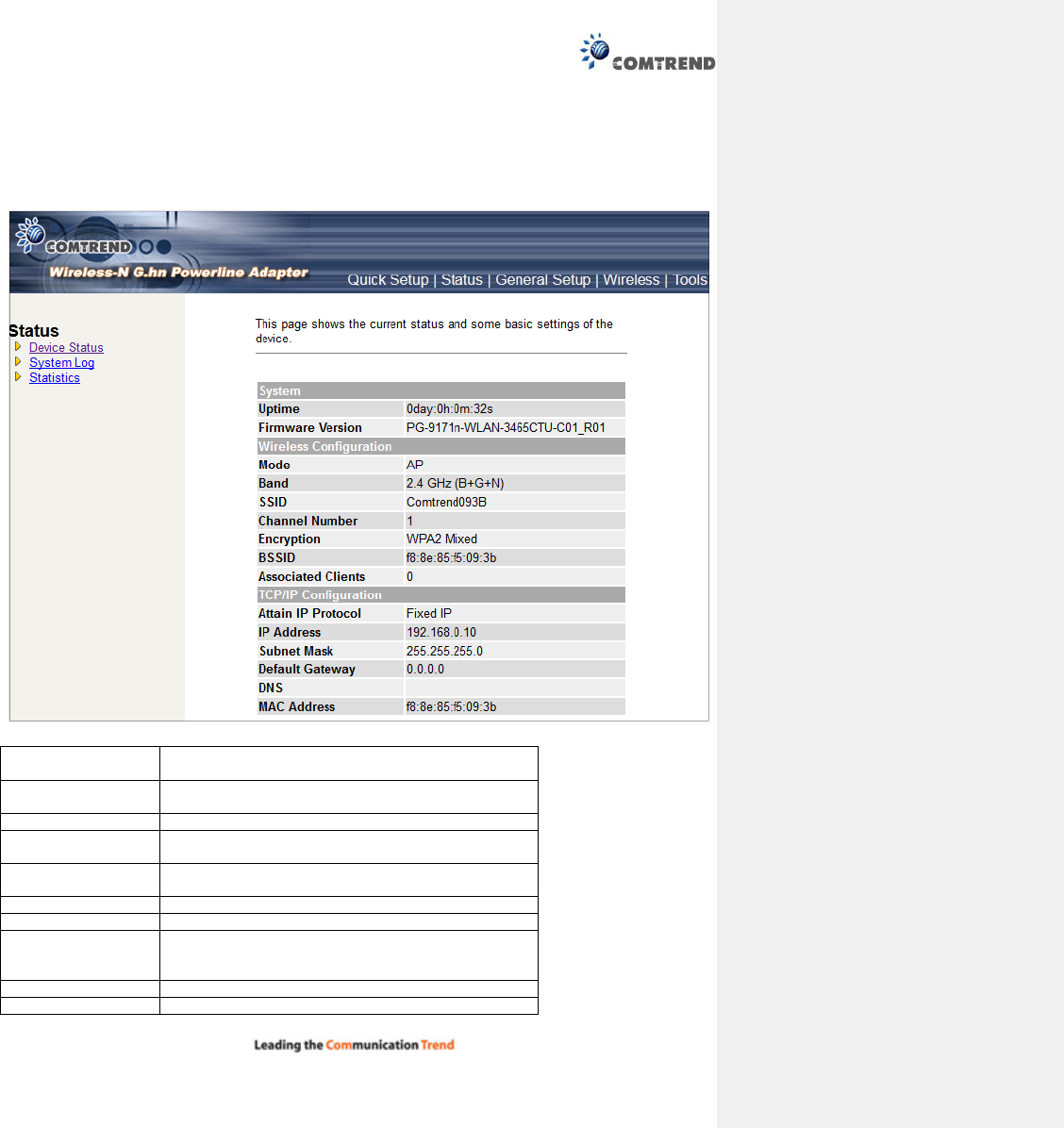
This page shows the current status and some basic settings of the device.
Up time Displays the total time passed since the Wireless-N
Powerline Adapter
was powered on.
Firmware Version Displays Firmware version of wireless Wireless-N
Powerline Adapter.
Mode
Displays current wireless operating mode
.
Band Displays the transmission mode (802.11b, 802.11n or
802.11g).
SSID Displays current SSID (the name used to identify this
Wireless-N Powerline Adapter).
Channel
Number
Displays current wireless channel number
.
Encryption Displays current wireless security setting.
BSSID Displays current BSSID (a set of unique identification
name of this Wireless-N Powerline Adapter, it cannot
be modified by
user)
.
Associated Clients
Displays the number of connected wireless client
s.
Attain IP Protocol
Displays the method of obtaining the IP address.
35
IP Address Displays the IP address of this Wireless-N Powerline
Adapter
.
Subnet Mask Displays the net mask of IP address.
Default Gateway
Displays the IP address of default gateway
.
DNS Displays the IP address of the DNS server.
MAC address
Displays the MAC address of WLAN interface
.
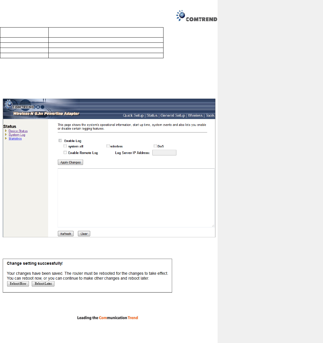
13.4.2 System Log
This page shows the system's operational information; start up time, system events, and also lets you
enable or disable certain logging features.
To enable the System Log tick the check box and make your selections.
Click the Apply Changes button to display the following.
Click the Reboot Now button for the changes to take effect. Click the Reboot Later button to continue to
make changes and reboot the device at a different time.
36
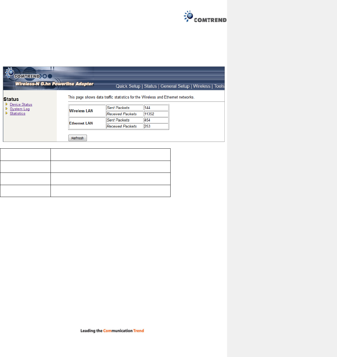
13.4.3 Statistics
This page shows the packet count for the Wireless and Ethernet LAN.
Wireless LAN
Sent Packets
It shows the statistic count of sent packets on the
wireless LAN interface
Wireless LAN
Received Packets
It shows the statistic count of received packets on the
wireless LAN interface
Ethernet LAN
Sent Packets
It shows the statistic count of sent packets on the
Ethernet LAN interface
Ethernet LAN
Received Packets
It shows the statistic count of received packets on the
Ethernet LAN interface
Click the Refresh button to update the Wireless/Ethernet LAN statistics.
37
13.5 General Setup
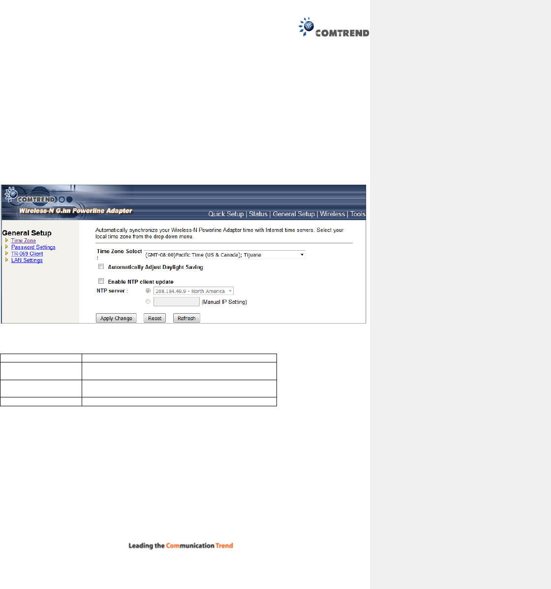
13.5.1 Time Zone Setting
Automatically synchronize your Wireless-N Powerline Adapter time with Internet time servers. Select your
local time zone from the drop-down menu.
This page is used to configure NTP client to get current time.
After clicking ‘Time Zone’ on the left of web management interface and the following will be displayed:
Time Zone Select
Select
the time zone in your country
Automatically Adjust
Daylight Saving
Click this box to enable or disable Automatically
Adjust Daylight
Saving function
Enable NTP client
update
Click the checkbox to enable NTP client update
NTP server Click select default or input NTP server IP address
38
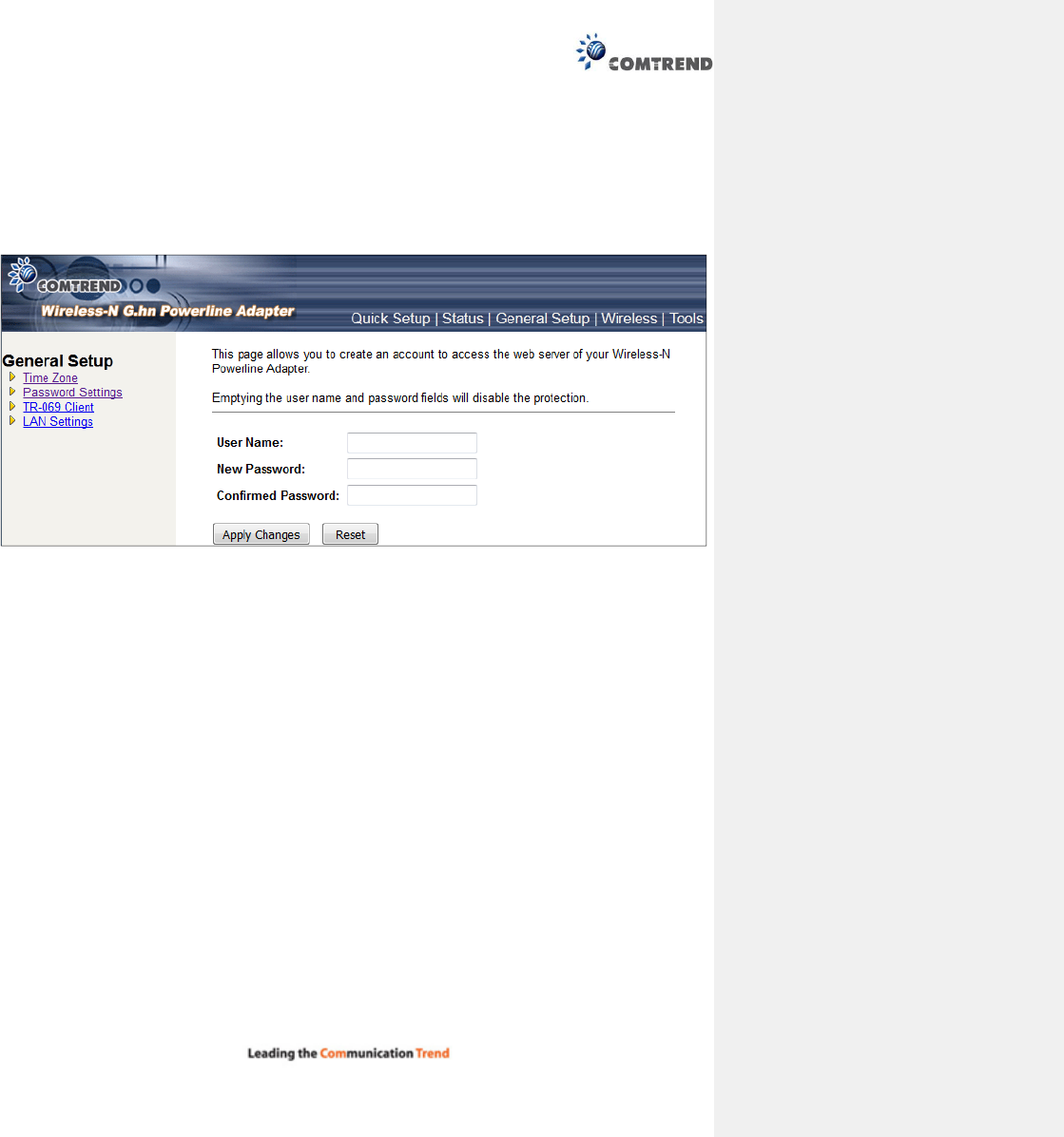
13.5.2 Password
This page is used to set the account to access the web server of your Wireless-N Powerline Adapter.
Emptying the user name and password fields will disable the protection.
Click the Apply Changes button to create the new password setting.
Click the Reset button to reset/clear the data just input on screen.
39
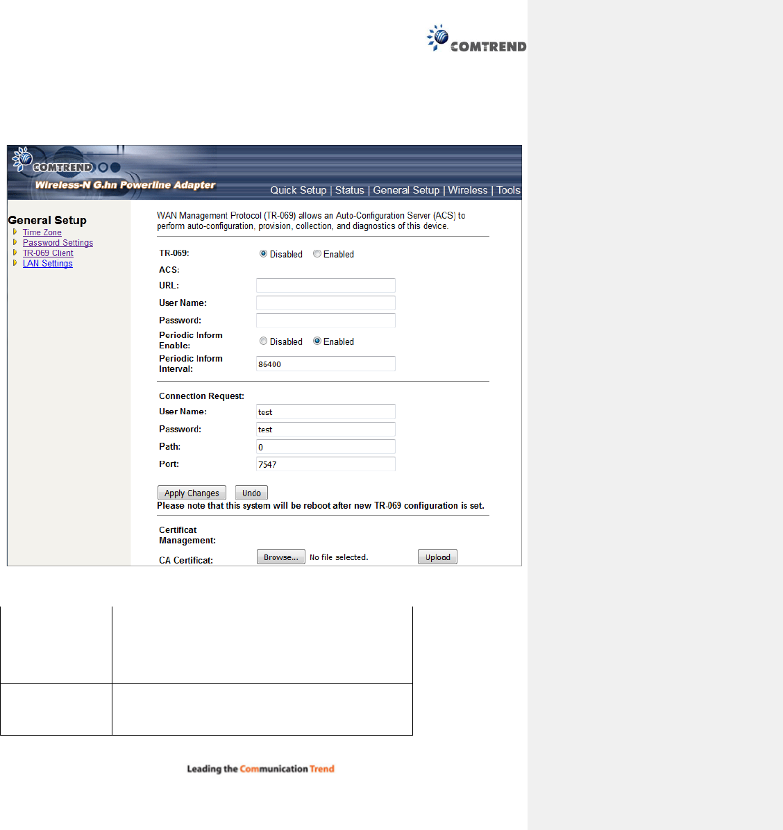
13.5.3 TR-069 Client
WAN Management Protocol (TR-069) allows an Auto-Configuration Server (ACS) to perform
auto-configuration, provision, collection, and diagnostics of this device.
Select desired values and click Apply Changes to configure TR-069 client options.
ACS URL URL for the CPE to connect to the ACS using the CPE WAN
Management Protocol. This parameter MUST be in the form
of a valid HTTP or HTTPS URL. An HTTPS URL indicates that
the ACS supports SSL. The “host” portion of this URL is
used by the CPE for validating the certificate from the ACS
when using certificate-based authentication.
ACS User Name Username used to authenticate the CPE when making a
connection to the ACS using the CPE WAN Management
Protocol. This username is used only for HTTP-based
authentication of the CPE.
40
ACS Password Password used to authenticate the CPE when making a
connection to the ACS using the CPE WAN Management
Protocol. This password is used only for HTTP-based
authentication of the CPE.
Periodic Inform
Enable
Whether or not the CPE periodically sends CPE information
to the ACS.
Periodic Inform
Interval
The duration in seconds of the interval for which the CPE
attempts to connect with the ACE if periodic inform is
enabled.
Connection Request
User Name Username used to authenticate an ACS making a
Connection Request to the CPE.
Password Password used to authenticate an ACS making a
Connection Request to the CPE.
Path This is an element in the makeup of the Connection Request
URL.
Port This is an element in the makeup of the Connection Request
URL.
41
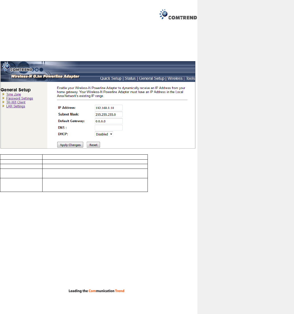
13.5.4 LAN Settings
Enable your Wireless-N Powerline Adapter to dynamically receive an IP Address from your home gateway.
Your Wireless-N Powerline Adapter must have an IP Address in the Local Area Network's existing IP range.
IP Address The IP address for the Wireless-N Powerline Adapter.
Subnet Mask
The Subnet Mask for the
Wireless
-
N Powerline Adapter
.
Default Gateway
The LAN default gateway
.
DNS Specify the IP address of the default gateway of your
network here.
DHCP Disable or Enable DHCP client. If Enabled, IP Address,
Subnet Mask, Default Gateway and DNS will be
obtained by DHCP client automatically.
Click the Apply Changes button to apply the amendments you made.
Click the Reset button to clear the data just inputted on the screen.
42
13.6 Wireless
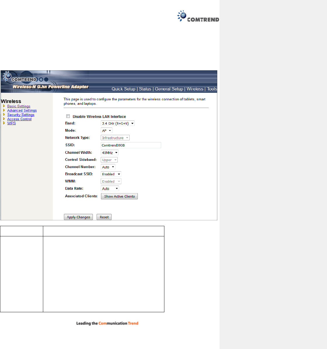
13.6.1 Basic settings
This page is used to configure the parameters for the wireless connection of tablets, smart phones, and
laptops.
Disable Wireless
LAN interface
Clicking it will disable your Wireless LAN Interface. The
Wireless Interface default is Enable.
Band Please select the wireless band you wish to use. By
selecting a different band setting, you’ll be able to allow
or deny the wireless client of a certain band.
If you select 2.4GHz (B), 2.4GHz (N), or 2.4GHz (G),
only wireless clients using the wireless band you select
(802.11b, 802.11 n, or 802.11g) will be able to connect
to this Wireless-N Powerline Adapter.
If you select 2.4GHz (B+G), then only wireless clients
using 802.11b and 802.11g band will be able to connect
to this Wireless-N Powerline Adapter.
If you want to allow 802.11b, 802.11g, and 802.11
Draft-N clients to connect to this Wireless-N Powerline
Adapter
, select 2.4GHz (B+G+N).

43
Mode PG-9171nsupports not only AP mode, but also provides
WDS, AP+WDS. Please refer to below for detailed
wireless Basic Settings. In Default, PG-9171n will work
with AP mode.
Network Type In Infrastructure Mode, wireless clients can access the
other networks (perhaps Internet) via this AP. For AP.
Only Infrastructure Mode is allowed here.
SSID Please input the ESSID (the name used to identify this
Wireless-N Powerline Adapter) here. You can input up to
32 alphanumerical characters. PLEASE NOTE THAT
THE ESSID IS CASE SENSITIVE.
Channel Width Select wireless channel width (bandwidth taken by
wireless signals of this Wireless-N Powerline Adapter).
It’s suggested to select ‘Auto 20/40MHz’. Do not change
to ’20 MHz’ unless you know what it is.
Control Sideband Specify if the extension channel should be in the Upper
or Lower sideband.
Channel
Number
Please select a channel number you wish to use. If you
know a certain channel number is being used by other
wireless access points nearby, please refrain from using
the same
channel number
Broadcast SSID Decide if the Wireless-N Powerline Adapter will broadcast
its own SSID or not. You can hide the SSID of your
Wireless-N Powerline Adapter (set the option to
‘Disable’), so only people those who know the SSID of
your
Wireless
-
N Powerline Adapter
can get connected.
WMM WMM (Wi-Fi Multimedia) technology, which can improve
the performance of certain network applications, like
audio/video streaming, network telephony (VoIP), and
others.
When you enable the WMM function, the Wireless-N
Powerline Adapter will define the priority of different
kinds of data, to give higher priority to applications which
require instant responding. Therefore you can improve
the performance of such network applications.
Data rate Set the wireless data transfer rate to a certain value.
Since most of wireless devices will negotiate with each
other and pick a proper data transfer rate automatically,
it’s not necessary to change this value unless you
know what will happen after modification.
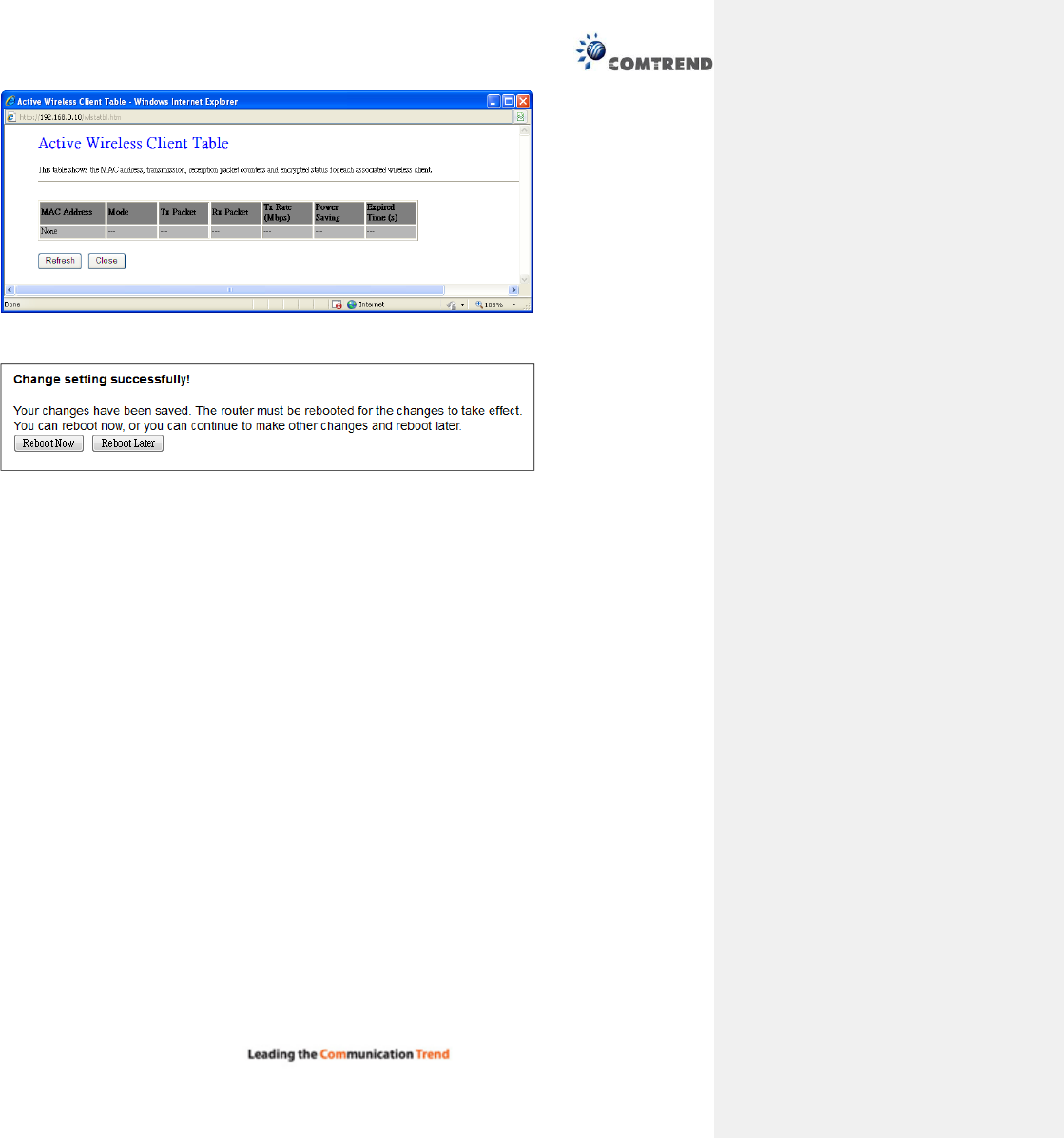
Associated Clients Click the ‘Show Active Clients’ button and a new popup
window will appear which contains the information about
all wireless clients connected to this Wireless-N
Powerline Adapter. You can click the ‘Refresh’ button in
the
popup window to kee
p information up
-
to
-
date.
Click the Show Active Clients button to display the following.
44
After you finish with the settings, please click ‘Apply Changes’, and the following message will be displayed:
When you see this message, the settings you made are successfully saved. You can click the ‘Reboot Later’
button to back to previous page and continue on other setting items, or click the ‘Reboot Now’ button to
restart the Wireless-N Powerline Adapter and the changes will take effect after about 30 seconds.
45
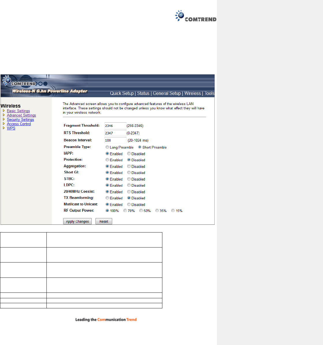
13.6.2 Advanced settings
This Wireless-N Powerline Adapter has many advanced wireless features. Please note that all settings listed
here are for experienced users only, if you’re not sure about the meaning and function of these settings,
please don’t modify them, or the wireless performance will be reduced.
You can click ‘Advanced Settings’ on the left to enter the advanced settings menu, and the following
message will be displayed:
Fragment Threshold Set the Fragment threshold of wireless radio. Do not
modify default value if you don’t know what it is,
default value is 2346
RTS Threshold Set the RTS threshold of wireless radio. Do not
modify default value if you don’t know what it is,
default
value is 2347
Beacon Interval Set the beacon interval of wireless radio. Do not
modify default value if you don’t know what it is,
default value is 100
Preamble Type Set the type of preamble of wireless radio, Do not
modify default value if you don’t know what it is,
default setting is ‘Short Preamble’
IAPP Click to enable or disable the IAPP function.
Protection
Click to enable or disable the Protection function.
Aggregation Click to enable or disable the Aggregation function.
46
Short GI Click to enable or disable the Short GI function.
STBC Click to enable or disable the STBC function.
LDPC Click to enable or disable the LDPC function.
20/40MHz Coexist Click to enable or disable the 20/40MHz Coexist
function.
TX Beamforming Click to enable or disable the TX Beamforming
function.
Multicast to Unicast Click to enable or disable the multicast to unicast
conversion function.
RF Output Power You can set the output power of wireless radio. Unless
you’re using this Wireless-N Powerline Adapter in a
really big space, you may not have to set output power
to 100%. This will enhance security (malicious /
unknown users in distance will not be able to
reach your Wireless
-
N Powerline Adapter).
After you finish with the settings, please click ‘Apply Changes’, and the following message will be displayed:
When you see this message, the settings you made are successfully saved. You can click the ‘Reboot Later’
button to go back to previous page and continue on other setting items, or click the ‘Reboot Now’ button
to restart the Wireless-N Powerline Adapter and the changes will take effect after about 30 seconds.
47
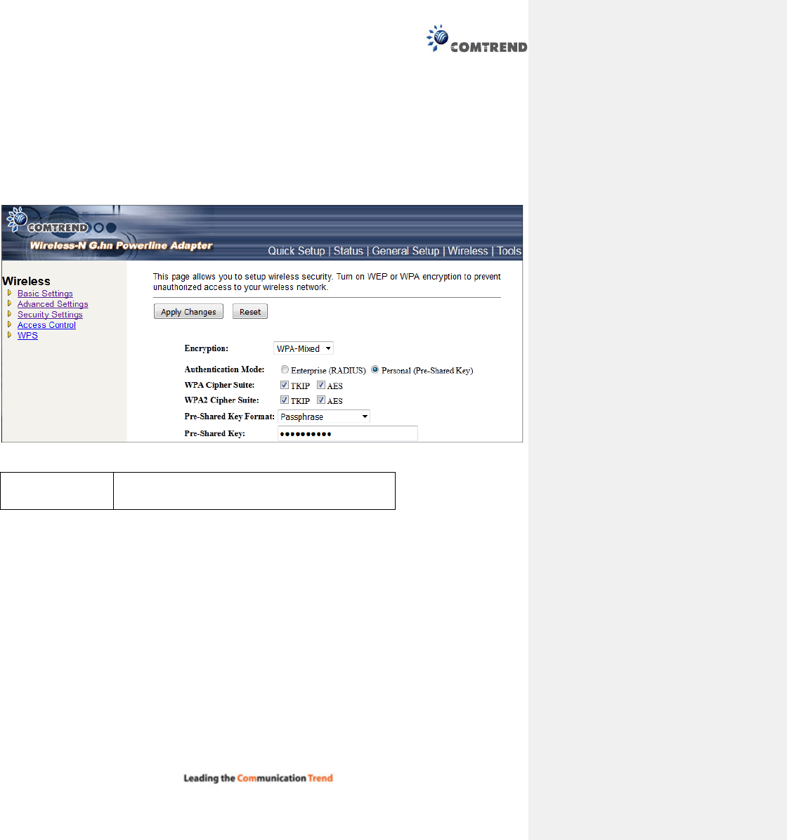
13.6.3 Security settings
This Wireless-N Powerline Adapter provides many types of wireless security (wireless data encryption).
When you use data encryption, data transferred by radio signals in the air will become unreadable for those
people who don’t know correct encryption key (encryption password).
You can click ‘Security Settings’ on the left to enter the security settings menu, and the following will be
displayed:
Encryption Select the encryption supported over wireless access.
The encryption method can be None, WEP, WPA(TKIP),
WPA2 or WPA2 Mixed
.
Different selections will produce different parameters.
48
13.6.3.1 Disable Security
When you select ‘Disable’, wireless encryption for the network is disabled.
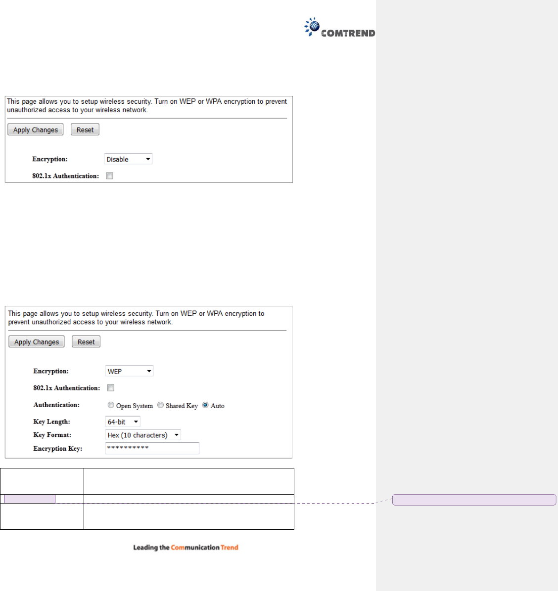
13.6.3.2 WEP
WEP (Wired Equivalent Privacy) is a common encryption mode, it’s safe enough for home and personal use.
But if you need higher level of security, please consider using WPA encryption (see next Section).
However, some wireless clients don’t support WPA, but only support WEP, so WEP is still a good choice for
you if you have such kind of client in your network environment.
When you select ‘WEP’ as the encryption type, the following will be displayed:
802.1x
Authentication
While WEP Encryption is selected.
Click the check box to enable the IEEE 802.1x
authentication function.
Authentication
Key Length There are two types of WEP key length: 64-bit and
128-bit. Using ‘128-bit’ is safer than ’64-bit’, but will
reduce some data transfer performance.
已註解 [Trevor2]: Please provide a description
49
Key Format There are two types of key format: ASCII and Hex. When
you select a key format, the number of characters of the
key will be displayed. For example, if you select ’64-bit’ as
key length, and ‘Hex’ as key format, you’ll see the
message at the right of ‘Key Format’ is ‘Hex (10
characters), which means the length of WEP key is 10
characters.
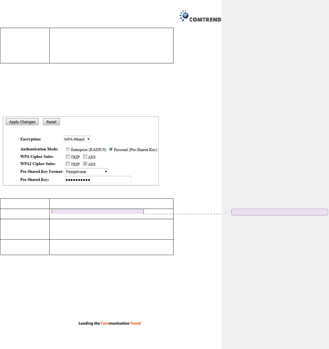
13.6.3.3 WPA/WPA2/WPA-Mix
WPA/WPA2/WPA-Mix are the safest encryption methods currently, and it’s recommended to use one of
these encryption methods to ensure the safety of your data.
In our example below we select ‘WPA-Mix’ as the encryption type. The following will be displayed:
WPA Authentication
Mode
Click to select the WPA-Mixed Authentication Mode with
Enterprise
(RADIUS) or Personal (Pre
-
Shared Key).
WPA/WPA2 Cipher
Suite
There are two type of Cipher :TKIP and AES
Pre-shared Key
Format
Please select the format of pre-shared key here, available
options are ‘Passphrase’ (8 to 63 alphanumerical
characters) and ‘Hex (64 hexadecimal characters – 0 to 9
and a to f).
Pre-shared Key Please input pre-shared key according to the key format
you selected here. For security reasons, don’t use simple
words).
已註解
[Trevor3]:
Please add to the description
50
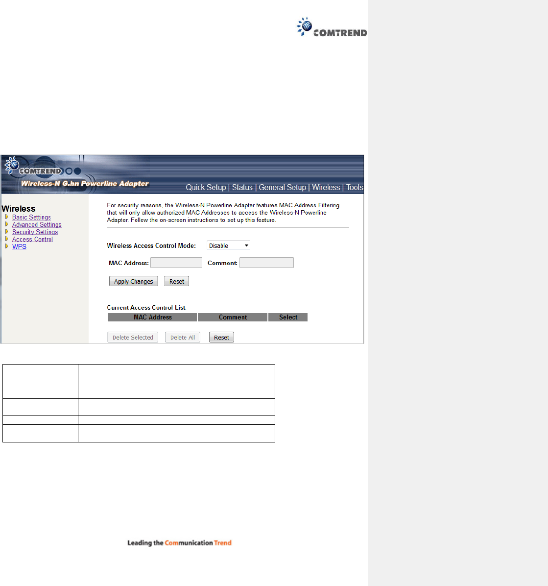
13.6.4 Access Control
Another security measure you can use to keep hackers and intruders away is ‘Access Control’. You can
pre-define a so-called ‘white-list’, which contains MAC addresses of the wireless clients you trust. All other
wireless client with the MAC address which is not in your list will be denied by this Wireless-N Powerline
Adapter.
To setup MAC filtering, please click ‘Access Control’ on the left of web management interface and the
following will be displayed:
Wireless Access
Control Mode
Click Disabled, Allow Listed or Deny Listed from the
drop down menu. This is a security control function;
only those clients registered in the access control list
can link to this WLAN Broadband Router.
MAC Address Fill in the MAC address of the client to register this
WLAN
Broadband Router access capabili
ty.
Comment Fill in the comment tag for the registered client.
Current Access
Control List
It shows the registered clients that are allowed to link
to this WLAN Broadband Router.
After you finish with the settings, please click ‘Apply Changes’.
51
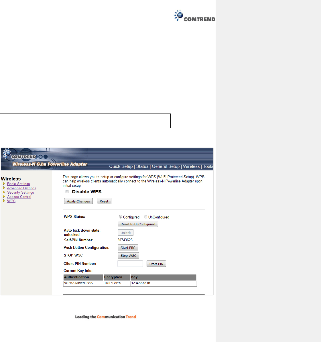
13.6.5 WPS
Wi-Fi Protected Setup (WPS) is the simplest way to build a connection between wireless network clients
and this Wireless-N Powerline Adapter. You don’t have to select encryption mode and input a long
encryption passphrase every time when you need to setup a wireless client, you only have to press a button
on wireless client and this Wireless-N Powerline Adapter, and the WPS will do the setup for you.
This Wireless-N Powerline Adapter supports two types of WPS: Push-Button Configuration (PBC), and PIN
code. If you want to use PBC, you have to switch this Wireless-N Powerline Adapter to WPS mode and push
a specific button on the wireless client to start WPS mode. You can push the Reset/WPS button of this
Wireless-N Powerline Adapter, or click the ‘Start PBC’ button in the web configuration interface to do this;
if you want to use PIN code, you have to provide the PIN code of the wireless client you wish to connect to
this Wireless-N Powerline Adapter and then switch the wireless client to WPS mode. The detailed
instructions are listed follow:
To use the WPS function to set an encrypted connection between this Wireless-N Powerline Adapter and
WPS-enabled wireless client by WPS, click ‘WPS’ on the left, and the following information will be displayed:
Note:
WPS function of this
Ethernet adapter
will not work for those wireless
clients that do not support WPS.
52
Disable WPS Check this box to enable or disable the WPS function.
WPS Status Displays WPS status. If data encryption settings of this
Wireless-N Powerline Adapter have never been set, the
‘unConfigured’ message will be displayed here; if data
encryption settings have been set before, the
‘Configured’ message will be displayed here.
Auto-lock-down
state
When WSC daemon is attacked by the wrong pin code
10 times, then WSC will enter lock-down state.
Self-PIN Number This is the WPS PIN code of this Wireless-N Powerline
Adapter. This code is useful when you need to build
wireless connection by WPS with other WPS-enabled
wireless devices.
Push Button
Configuration
Click ‘Start PBC’ to start the Push-Button style WPS
setup procedure. This Wireless-N Powerline Adapter
will wait for WPS requests from wireless clients for 2
minutes. The ‘WLAN’ LED on the Wireless-N Powerline
Adapter will be steady on for 2 minutes when this
Wireless-N Powerline Adapter is waiting for an
incoming WPS request.
STOP WSC Click ‘Stop WSC’ to stop WPS setup procedure.
Client PIN Number Please input the PIN code of the wireless client you via
client wish to connect, and click the ‘Start PIN’ button.
The ‘WLAN’ LED on the Wireless-N Powerline Adapter
will be steady on when this Wireless-N Powerline
Adapter
is waiting for incoming WPS request.
NOTE: When you’re using PBC type WPS setup, you must press the ‘PBC’
button (hardware or software) of the wireless client within 120 seconds; if
you didn’t press PBC button of the wireless client within this time period,
please press ‘PBC’ button (hardware or software) of this access point again.
53
13.7 Tools
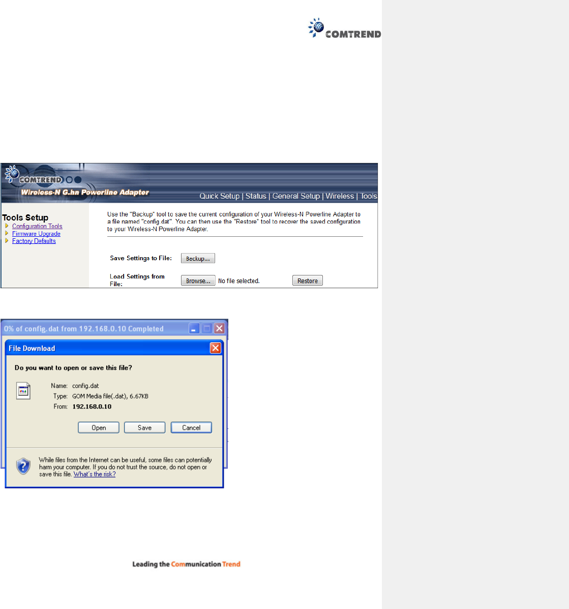
13.7.1 Configuration Tools
Use the "Backup" tool to save the current configuration of your Wireless-N Powerline Adapter to a file
named "config.dat". You can then use the "Restore" tool to recover the saved configuration to your
Wireless-N Powerline Adapter.
Click the Backup button to display the following.
Click the Save button to backup your current configuration.
54
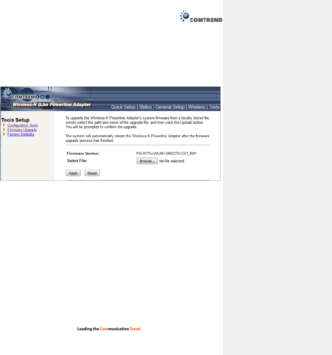
13.7.2 Firmware Upgrade
This page allows you upgrade the Wireless-N Powerline Adapter firmware to the new version. Please note,
do not power off the device during the upload as it may crash the system.
After clicking ‘ Upgrade Firmware’ on the left of web management interface and the following will be
displayed:
Click the Browse button to locate the file.
Click the Apply button to apply the upgrade.
55
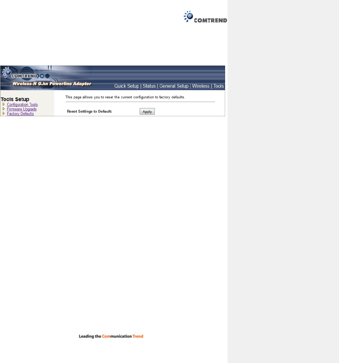
13.7.3 Factory Defaults
This page allows you to reset the current configuration to factory defaults.
Click the Apply button to reset the configuration.