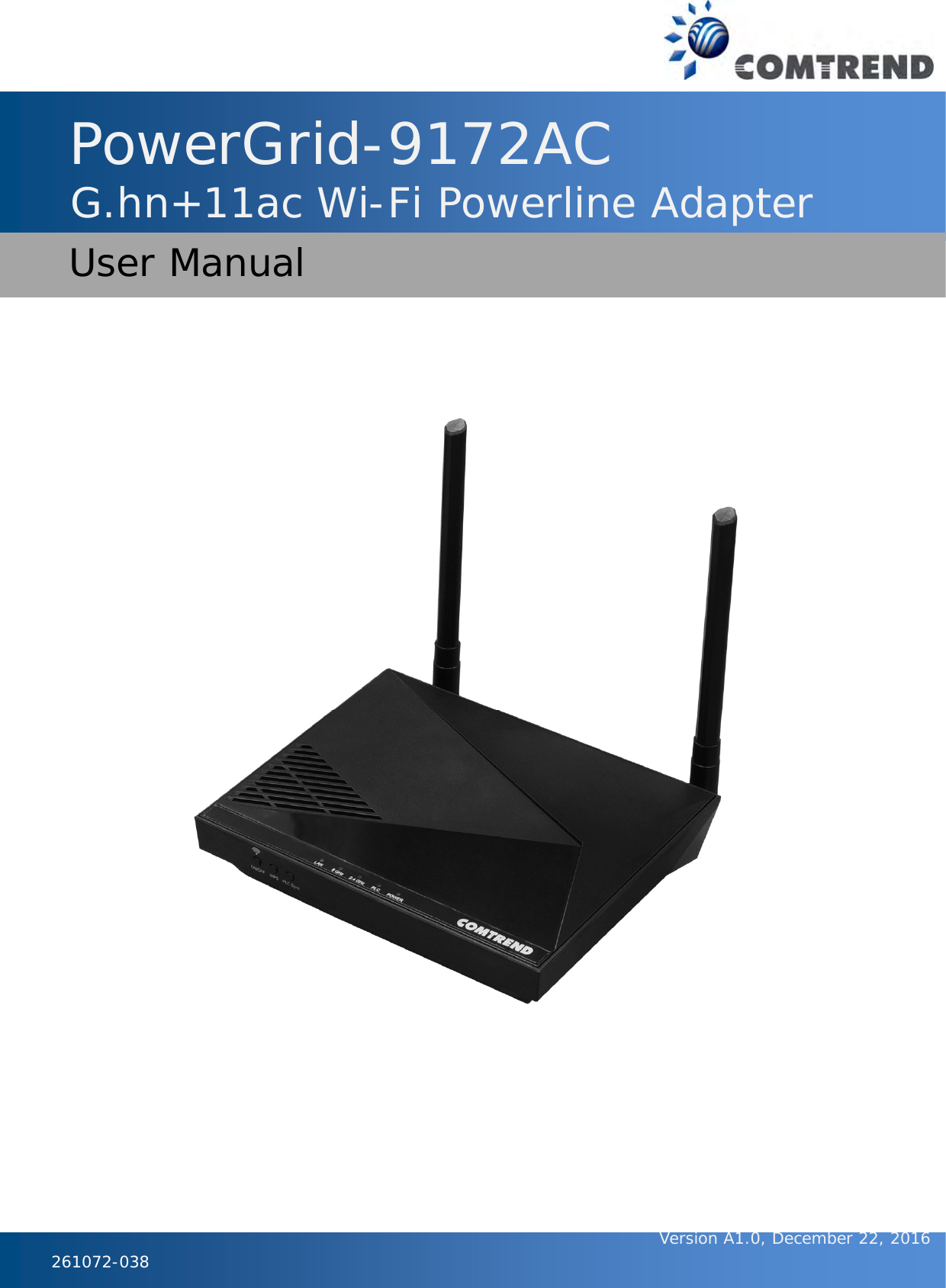
Comtrend PG9172AC G.hn+11ac WiFi Powerline Adapter User Manual
Comtrend Corporation G.hn+11ac WiFi Powerline Adapter
UserManual.wiki
>
Comtrend
>
PG9172AC User Manual
User manual
Navigation menu
Upload a User Manual
Namespaces
Wiki Guide
HTML
PDF
Info
Views
User Manual
Discussion / Help
Navigation
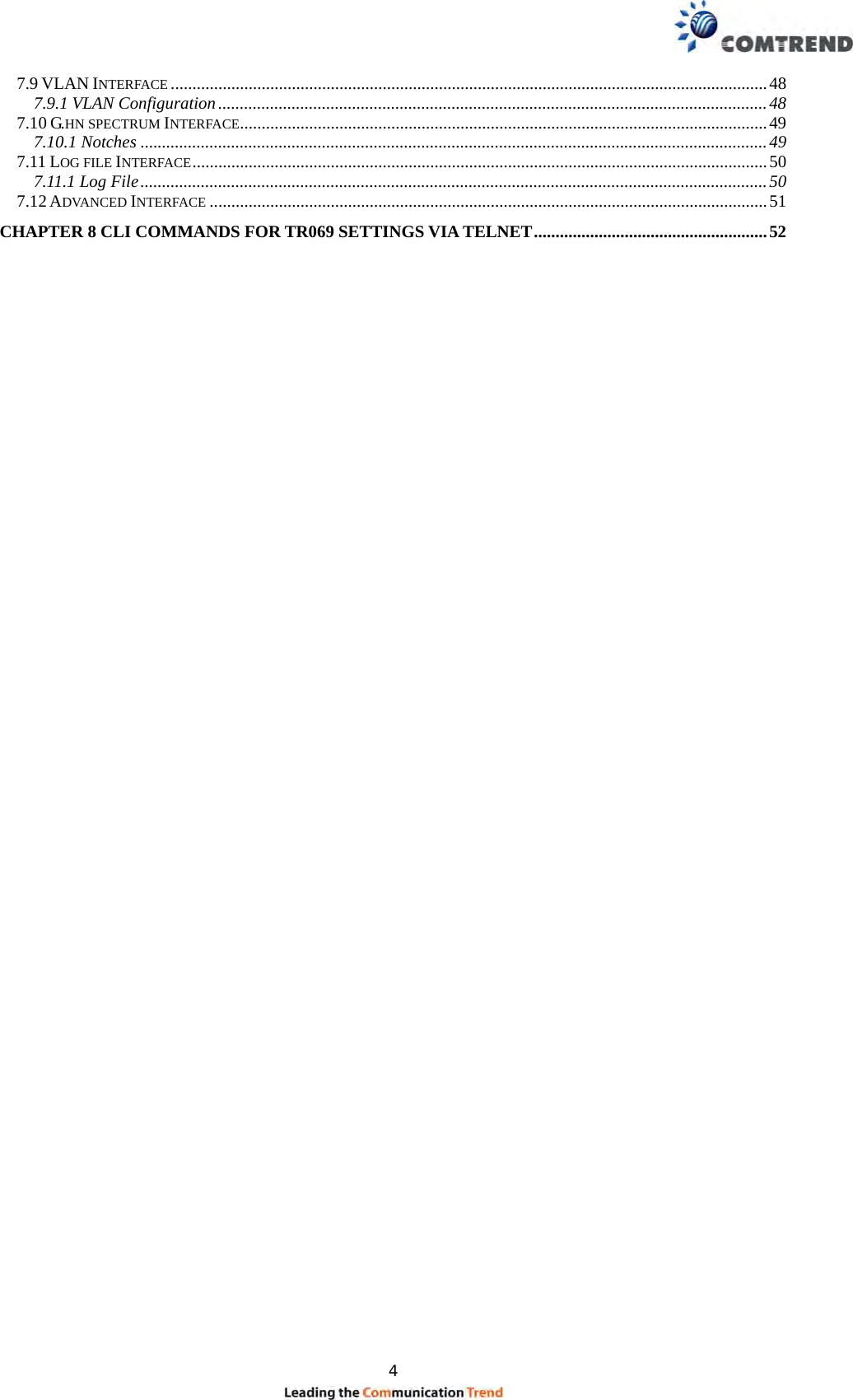
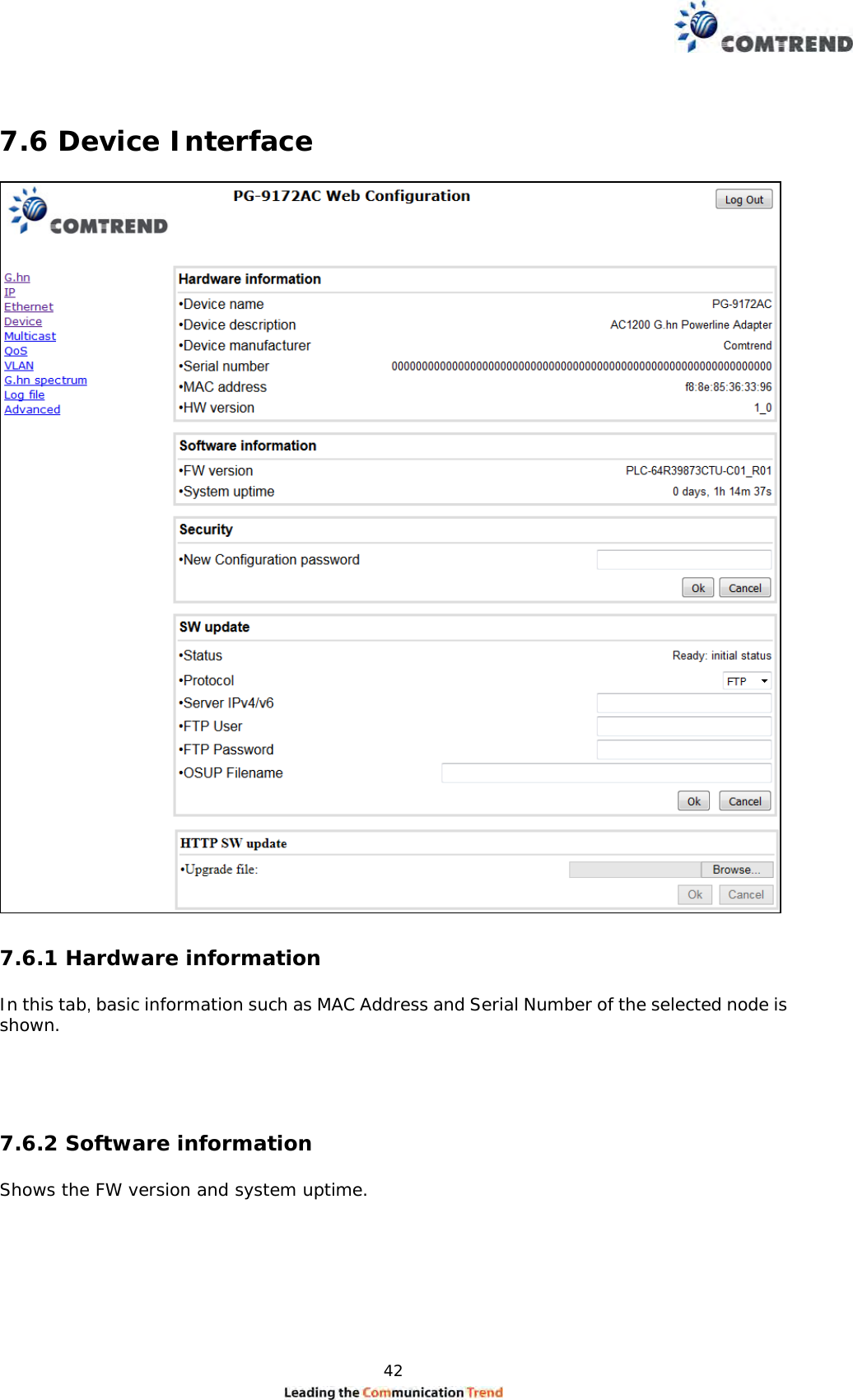
![47 Example If QoS criterion: 802.1p, all other options are grayed out, and follow the QoS rules below. According to G.9960 specs, the priority mapping recommended by [IEEE 802.1D] subclause 7.7.3 is presented in Table III.1. for four priority queues. PCP Priority Acronym Traffic Types 1 0 (Third) BK Background 0 1 (lowest) BE Best Effort 2 2 (lowest) EE Excellent Effort 3 3 (Third) CA Critical Applications 4 4 (second) VI Video, < 100 ms latency and jitter 5 5 (second) VO Voice, < 10 ms latency and jitter 6 6 (highest) IC Internetwork Control 7 7 (highest) NC Network Control In summary, the sequence of priority queue, (7,6) > (5,4) > (3,0) > (2,1)](https://usermanual.wiki/Comtrend/PG9172AC/User-Guide-3527652-Page-48.png)
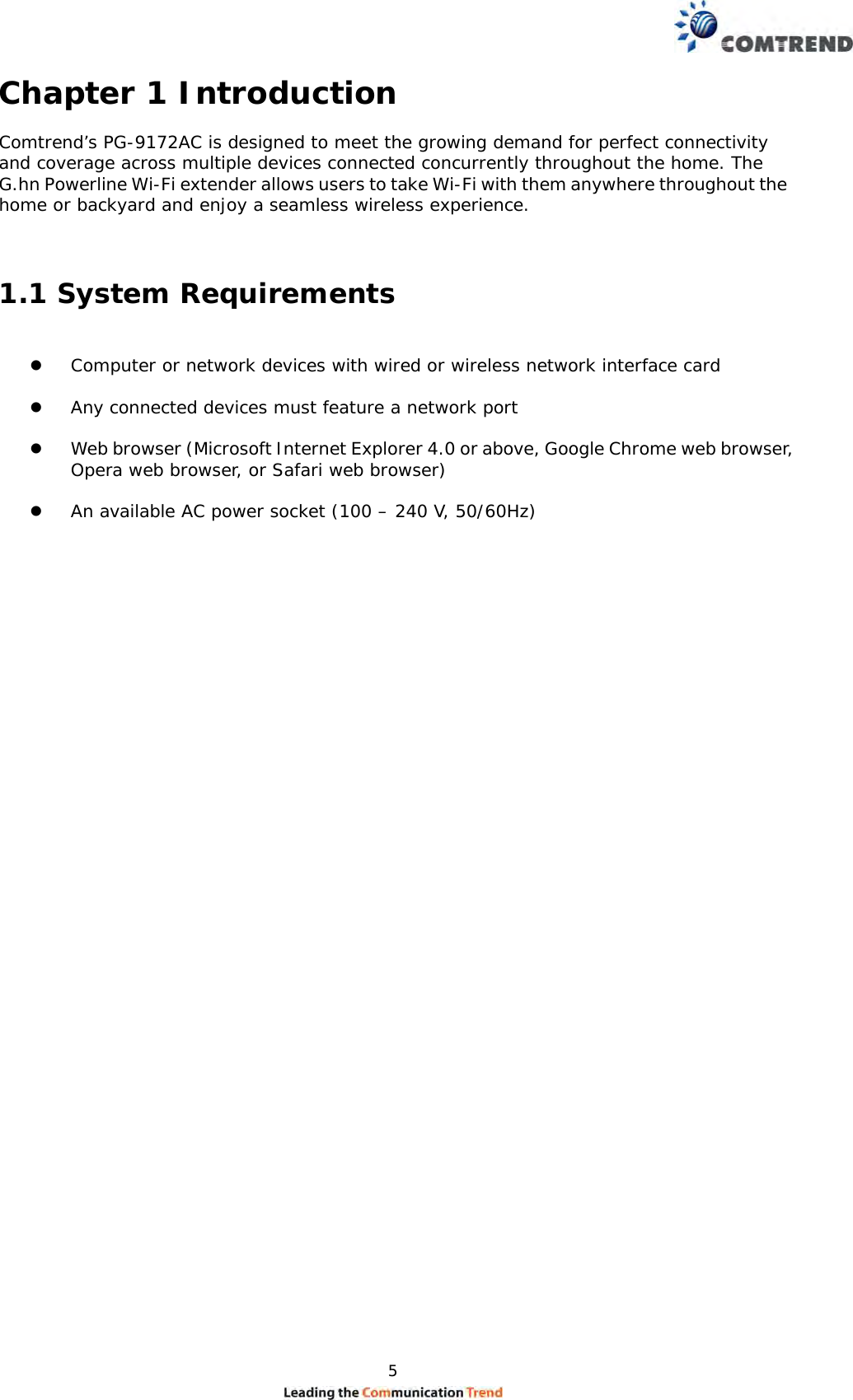
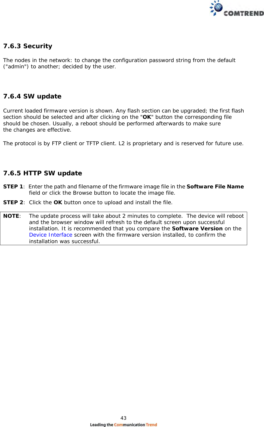
![52 Chapter 8 CLI commands for TR069 settings via Telnet A system reboot is required for new settings. ACS URL settings, nvram_set 2860 TR069URL [http://domain or IP/string] For example: nvram_set 2860 TR069URL http://220.128.128.235/cpe/?pd128 Display the current settings, nvram_get 2860 TR069URL ACS username, nvram_set 2860 TR069Username [username] For Example: nvram_set 2860 TR069Username comtrend Display the current settings, nvram_get 2860 TR069Username ACS password, nvram_set 2860 TR069Password [password] For example: nvram_set 2860 TR069Password comtrend Display the current settings, nvram_get 2860 TR069Password Periodic interval in seconds. nvram_set 2860 TR069InformInterval [seconds] For example: nvram_set 2860 TR069InformInterval 3600 Display the current settings, nvram_get 2860 TR069InformInterval](https://usermanual.wiki/Comtrend/PG9172AC/User-Guide-3527652-Page-53.png)