Comtrend PG9172AC G.hn+11ac WiFi Powerline Adapter User Manual
Comtrend Corporation G.hn+11ac WiFi Powerline Adapter
Comtrend >
User manual
2
6
1
0
72-
038
Version A1.0, December 22, 2016
PowerGrid-9172AC
G.hn+11ac Wi-Fi Powerline Adapter
User Manual

1
Preface
This manual provides information related to the installation and operation of this device. The
individual reading this manual is presumed to have a basic understanding of
telecommunications terminology and concepts.
If you find the product to be inoperable or malfunctioning, please contact technical support
for immediate service by email at homesupport@comtrend.com
For product update, new product release, manual revision, or software upgrades, please visit
our website at http://www.comtrend.com
Important Safety Instructions
In order to keep the safety of users and your properties, please follow these safety
instructions:
1. This power line access point is designed for indoor use only; DO NOT place this power line
access point outdoor.
2. DO NOT put this power line access point at or near hot or humid places, like a kitchen or
bathroom. Also, do not leave this power line access point in the car under direct sunlight.
3. DO NOT pull any connected cable with force; disconnect it from the power line access point
first.
4. If you want to place this power line access point at high places, please make sure the
power line access point is firmly secured. Falling from high places would damage the power
line access point and its accessories, and warranty will be void.
5. There’s no user-serviceable part inside the access point. If you found that the power line
access point is not working properly, please contact your dealer of purchase and ask for help.
DO NOT disassemble the access point, warranty will be void.
6. If the power line access point falls into water when it’s powered, DO NOT use your hand to
pick it up. Switch the electrical power off before you do anything, or contact an
experienced electrical technician for help.
2
Copyright
Copyright©2017 Comtrend Corporation. All rights reserved. The
information contained herein is proprietary to Comtrend Corporation. No part of this
document may be translated, transcribed, reproduced, in any form, or by any means without
prior written consent of Comtrend Corporation.
This program is free software: you can redistribute it and/or modify it under the terms of the
GNU General Public License as published by the Free Software Foundation, either version 3 of
the License, or (at your option) any later version.
This program is distributed in the hope that it will be useful, but WITHOUT ANY WARRANTY;
without even the implied warranty of MERCHANTABILITY or FITNESS FOR A PARTICULAR
PURPOSE. See the GNU General Public License for more details.
You should have received a copy of the GNU General Public License along with this
program. If not, see http://www.gnu.org/licenses/
NOTE: This document is subject to change without notice.
Protect Our Environment
This symbol indicates that when the equipment has reached the end
of its useful life, it must be taken to a recycling centre and processed
separate from domestic waste.
The cardboard box, the plastic contained in the packaging, and the parts that make up this
device can be recycled in accordance with regionally established regulations. Never dispose
of this electronic equipment along with your household waste; you may be subject to
penalties or sanctions under the law. Instead, please be responsible and ask for disposal
instructions from your local government.

3
CATALOG
CHAPTER 1 INTRODUCTION ............................................................................................................................ 5
1.1 SYSTEM REQUIREMENTS ................................................................................................................................... 5
CHAPTER 2 HOW TO INSTALL PG-9172AC .................................................................................................... 6
CHAPTER 3 LED INDICATIONS ...................................................................................................................... 12
CHAPTER 4 BUTTON FUNCTIONS ................................................................................................................. 13
CHAPTER 5 WIRELESS SYSTEM AND NETWORK SETUP ...................................................................... 14
5.1 CONNECT TO POWER LINE ACCESS POINT BY WEB BROWSER ........................................................................... 14
5.2 CONNECTING TO WEB MANAGEMENT INTERFACE .......................................................................................... 15
5.3 VIEW SYSTEM INFORMATION .......................................................................................................................... 16
5.4 NETWORK SETTINGS ....................................................................................................................................... 18
5.5 STATIONS LIST ................................................................................................................................................ 18
5.6 NETWORK TIMING .......................................................................................................................................... 19
5.7 ACCESS POLICY .............................................................................................................................................. 20
5.8 ADMINISTRATION ............................................................................................................................................ 21
5.9 MONITOR ........................................................................................................................................................ 22
5.10 LOGOUT ........................................................................................................................................................ 22
CHAPTER 6 WIRELESS CONFIGURATIONS ................................................................................................ 23
6.1 2.4G WIRELESS SETTINGS ............................................................................................................................. 23
6.1.1 Multiple BSS ........................................................................................................................................... 24
6.2 2.4G SECURITY SETTINGS .............................................................................................................................. 25
6.3 2.4G WPS SETTINGS ...................................................................................................................................... 26
6.4 2.4G AIR TIME MANAGEMENT ....................................................................................................................... 27
6.4.1 2.4Ghz Air Time Management ................................................................................................................ 27
6.4.2 Configuration ......................................................................................................................................... 28
6.4.3 Per BSS Weights ..................................................................................................................................... 28
6.4.4 Per Station Weights ................................................................................................................................ 28
6.5 5G WIRELESS SETTINGS ................................................................................................................................ 29
6.5.1 Multiple BSS ........................................................................................................................................... 30
6.6 5G SECURITY SETTINGS ................................................................................................................................. 31
6.7 5G WPS SETTINGS ......................................................................................................................................... 32
6.8 5G AIR TIME MANAGEMENT .......................................................................................................................... 33
6.8.1 5Ghz Air Time Management................................................................................................................... 33
6.8.2 Configuration ......................................................................................................................................... 34
6.8.3 Per BSS Weights ..................................................................................................................................... 34
6.8.4 Per Station Weights ................................................................................................................................ 34
CHAPTER 7 G.HN/POWERLINE SETUP ......................................................................................................... 35
7.1 CONFIGURE STATIC IP MODE ...................................................................................................................... 35
7.2 LOGGING IN .................................................................................................................................................... 36
7.3 G.HN INTERFACE ............................................................................................................................................. 37
7.3.1 Basic Configuration ................................................................................................................................ 38
7.3.2 NDIM Configuration ............................................................................................................................... 38
7.3.3 Encryption Configuration via WEB UI ................................................................................................... 38
7.4 IP INTERFACE .................................................................................................................................................. 39
7.4.1 IP config .................................................................................................................................................. 40
7.5 ETHERNET INTERFACE .................................................................................................................................... 41
7.6 DEVICE INTERFACE ......................................................................................................................................... 42
7.6.1 Hardware information ............................................................................................................................ 42
7.6.2 Software information ............................................................................................................................... 42
7.6.3 Security ................................................................................................................................................... 43
7.6.4 SW update ............................................................................................................................................... 43
7.6.5 HTTP SW update ..................................................................................................................................... 43
7.7 MULTICAST INTERFACE ................................................................................................................................... 44
7.7.1 MCAST Configuration ............................................................................................................................ 44
7.8 QOS MENU ...................................................................................................................................................... 45
7.8.1 QoS Configuration .................................................................................................................................. 45

4
7.9 VLAN INTERFACE .......................................................................................................................................... 48
7.9.1 VLAN Configuration ............................................................................................................................... 48
7.10 G.HN SPECTRUM INTERFACE .......................................................................................................................... 49
7.10.1 Notches ................................................................................................................................................. 49
7.11 LOG FILE INTERFACE ..................................................................................................................................... 50
7.11.1 Log File ................................................................................................................................................. 50
7.12 ADVANCED INTERFACE ................................................................................................................................. 51
CHAPTER 8 CLI COMMANDS FOR TR069 SETTINGS VIA TELNET ...................................................... 52

5
Chapter 1 Introduction
Comtrend’s PG-9172AC is designed to meet the growing demand for perfect connectivity
and coverage across multiple devices connected concurrently throughout the home. The
G.hn Powerline Wi-Fi extender allows users to take Wi-Fi with them anywhere throughout the
home or backyard and enjoy a seamless wireless experience.
1.1 System Requirements
Computer or network devices with wired or wireless network interface card
Any connected devices must feature a network port
Web browser (Microsoft Internet Explorer 4.0 or above, Google Chrome web browser,
Opera web browser, or Safari web browser)
An available AC power socket (100 – 240 V, 50/60Hz)
6
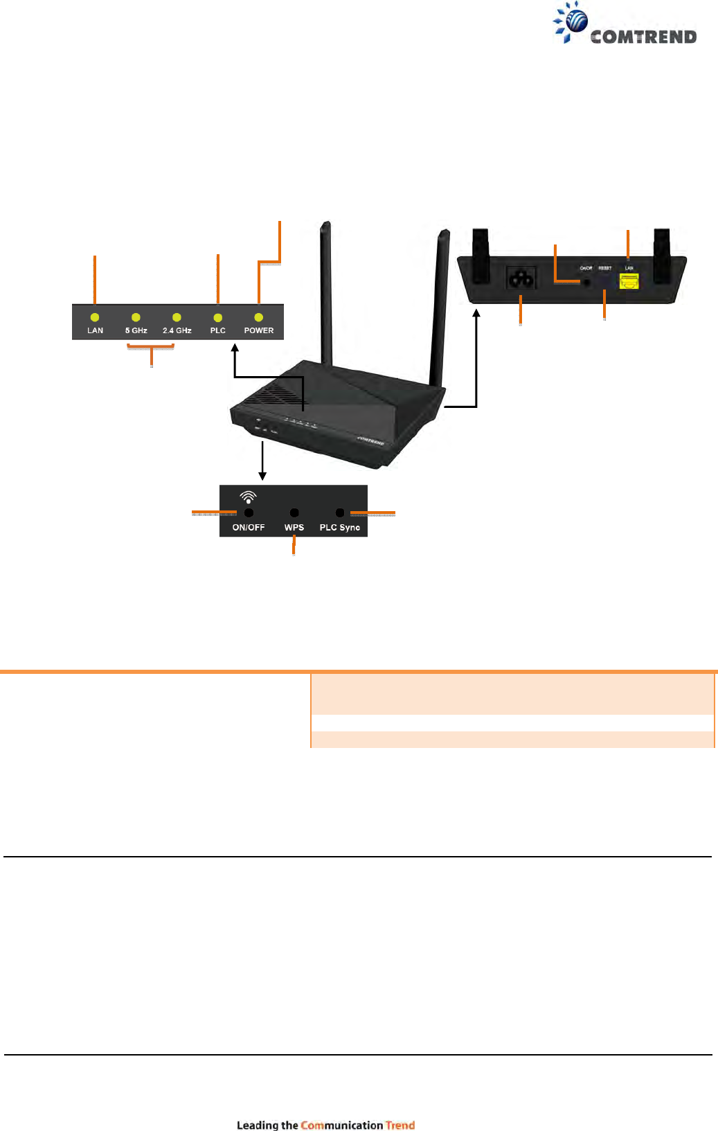
Chapter 2 How to Install PG-9172AC
(A) Understanding the AC1200 G.hn Powerline Adapter
How to Create a Basic (2 unit) G.hn Powerline Network
A G.hn Powerline Network can consist of a minimum of 2 and up to 16 devices total.
**The PG-9172 can be replaced by another G.hn Powerline Adapter.
NOTE: The following steps show how to create or add onto a G.hn Powerline Network using
a PG-9172AC.
(A minimum of two G.hn Powerline Adapters are required to create a proper connection.)
If this is the first time you are setting up a G.hn Powerline Network please continue to
Section B.
If you already have an established G.hn Powerline Network and are adding an additional
adapter, please skip to Section C.
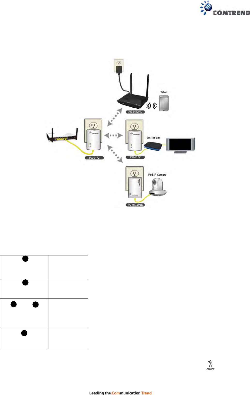
Purpose Recommended
Primary Adapter Second Adapter
Connecting a single dedicated Internet
Device PG-9172** PG-9172**
Bringing wireless to a remote location PG-9172** PG-9172AC
Connecting a PoE Enabled Device PG-9172** PG-9172PoE
Displays Ethernet
Connection Status
Displays Power
Status
Displays
Adapter
Connection
Status
Displays 2.4GHz/5GHz
Enabling/Disabling WiFi
Status
Reset Button
Press for more
than10
seconds for
Factory Reset.
WPS Connection Button
Gigabit
Ethernet Port
Power Port
WiFi Power
On/Off Button
On/Off
Power Button
Adapter Pairing
Button
7
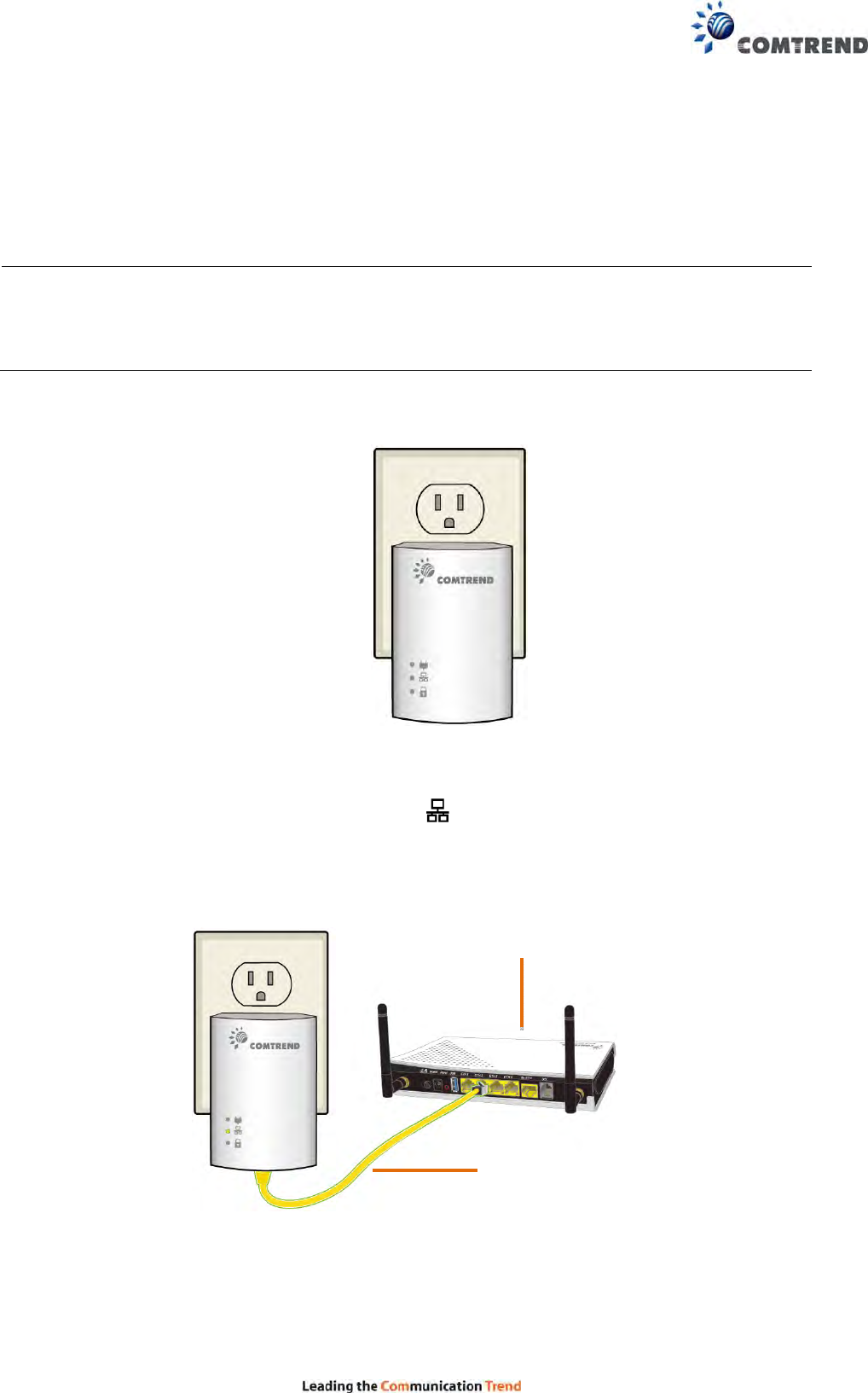
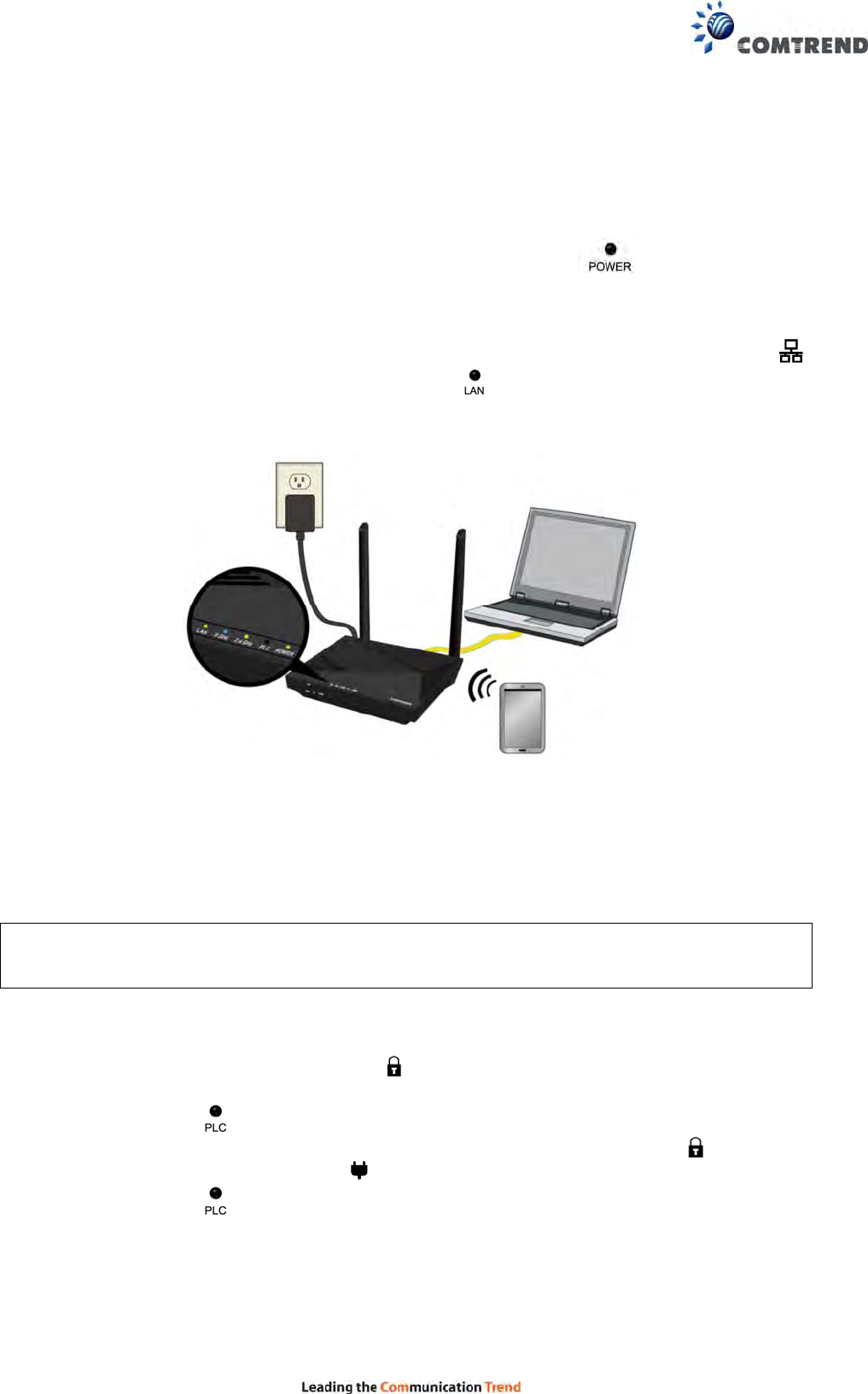
(B) Creating a New G.hn Network
1. Plug a PG-9172* unit into the power outlet closest to the Network Device (Modem,
Router). Do not plug the adapter into a power strip or surge protector, as network
performance could degrade significantly.
*NOTE: It is suggested that you use the PG-9172 as the primary connection to the
Network Device, however, the PG-9172 can be replaced by another G.hn
Powerline Adapter.
2. Connect the PG-9172 to a Network Device with an Ethernet (RJ-45) cable. (Wait 10
seconds for the Network Indicator to light up GREEN, which indicates a
good connection. A flashing GREEN light indicates that the device has a
good connection and is also sending data).
Network Device
(
Modem
,
Router
)
Ethernet Cable
PG-9172
PG-9172
8
(C) Adding to an Existing G.hn Network
3. Plug the PG-9172AC into the power outlet closest to the location you want to
add wireless and/or near an Internet-Enabled Device you would like to
directly connect to the adapter. The Power Indicator should light up.
4. Optionally, to add an Internet- Enabled Device, directly connect the PG-9172AC to
the Internet-Enabled Device with an Ethernet cable. (The Network Indicator
on the PG-9172 and the LAN Indicator of the PG-9172AC should both be
GREEN representing a strong connection).
(D) Security Setup
NOTE: G.hn Adapters will automatically “pair” in “non-secure” mode. It is highly
recommended to follow Step 5 to create a secure connection.
5. Press the “Config” Button of a PG-9172 in the existing network for 2 seconds. You
will see the Security Indicator start flashing GREEN. Within two minutes,
press the “PLC Sync” Button on the PG-9172AC for 2 seconds until you see the PLC
Indicator start flashing GREEN. (When the adapters are successfully
paired with a strong connection the PG-9172’s Security Indicator
and Connection Indicator will be solid GREEN and the PG-9172AC’s PLC
Indicator will be solid GREEN.)
6. Repeat Steps 3 to 5 to add additional adapters/devices.
9
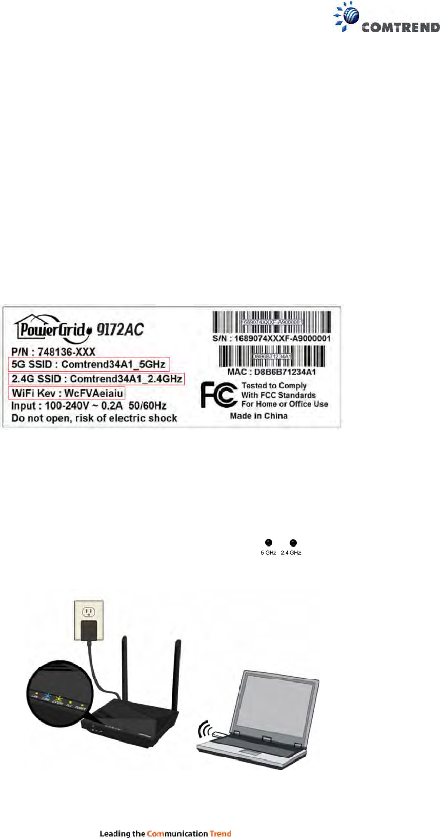
(E) Connecting Your WiFi Devices to the New PG-9172AC
Access Point
7. For some devices (E.g. laptops, cameras, set-top-boxes, etc.)
wireless connectivity can be done via WPS (Wireless Protected Setup). WPS allows
you to simply connect devices to the new Access Point without entering a
username/password manually. To do this, please follow the instructions in
Section F below.
8. You have created a new Internet Access Point and it is now active and ready to use!
To connect your WiFi devices to your new PG-9172AC WiFi Access Point, select the
PG-9172AC Access Point using your WiFi device’s standard network list. The
Network Name (SSID) and Password (WiFi Key) can be found on the bottom of the
PG-9172AC.
9. Go to Section G.
(F) Setup of Wireless Devices via WPS
(WiFi Protected Setup)
10. Press and hold the “WPS” Button for more than 2 seconds on the PG-9172AC to
activate its WPS. The PG-9172AC’s WiFi Indicators should flash to
indicate a WPS connection is in progress.
11. Within two minutes, press the “WPS” Button (often the WPS/Reset Button) on your
remote Internet-Enabled Devices to activate WPS.
10
12. The devices will establish a secure connection.
(G) You Have Successfully Installed Your G.hn Powerline
Adapter with WiFi!
(H) Troubleshooting
The following information should help you diagnose basic setup or installation problems.
1) POWER Indicator is OFF: First try pressing the
“Power” Button on the rear panel of the device. If the
Power Indicator is still off, please make sure that your
power socket is working properly (perhaps by testing with
another device). Then plug in your PG-9172AC again
and push the “Power” Button on the rear panel of the
device.
2) LAN Indicator is OFF: The LAN Indicator is off when
there is no directly connected device into the G.hn
Adapters’ Ethernet Port. If there is a
device connected and if the LAN Indicator is off, check
that the Ethernet port of the Powerline Adapter
is connected firmly to the Ethernet port of the other
device. Also, you can check the condition of the
Ethernet cable by using another Ethernet cable to test if
the indicator turns on.
3) WiFi Indicators are OFF: To turn on both indicators
(enable WiFi) you can press the “WiFi” Button on the
front of the device. You can also login to the G-9172AC
Web and enable WiFi (5G only). See section 5.5 of the
POWER
LAN
WiFi
PLC
PLC
POWER
LAN
5 GHz 2.4 GHz
11
User Manual for details.
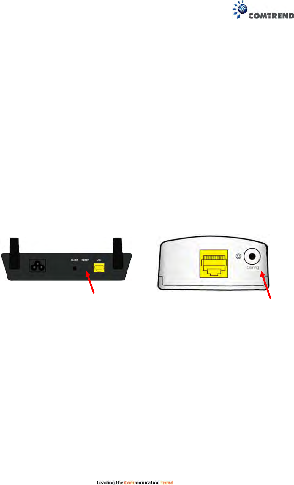
4) PLC Indicator is OFF: This indicator shows that the adapter is paired to the G.hn
Network. If this indicator is off, plug both Powerline Adapters that you’re attempting to pair
into power outlets that are located within the same room. All of the indicators of the device
should blink (approx. 10 seconds), and the PLC Indicator should light up. If the PLC
Indicator does not light up, it may indicate the existing G.hn network is secure and you
have to pair the PG-9172AC to it in “secure mode.” To do so, press the "PLC Sync" Button on
the PG-9172AC for 2 seconds. Within 2 minutes, press the “Config" Button on the PG-9172
for 2 seconds (Holding for more than 4 seconds will clear the security key and require a
re-pairing). The PLC Indicator will then light up GREEN. Afterwards, you can plug the units
back into their original location.
5) PLC Indicator is Blinking RED: This indicator shows that the adapter is paired to the
G.hn Network. If the PLC Indicator is blinking RED, then the adapter is
paired in “non-secure” mode to the G.hn Network. It is optional to pair the device in “secure
mode.” To pair the device in “secure mode," press the "PLC Sync" Button on the PG-9172AC
and the “Config" Button on the PG-9172 for 2 seconds. The PLC Indicator will then light
up GREEN.
* If you have tried all of the above and are still experiencing problems, you can reset all
devices to factory default by pushing the “Reset” Button on the PG-9172AC for more than 10
seconds AND the “Config” Button on the PG-9172 for 10 seconds.
251841536
FOR MORE HELP: For instructions on advanced features, FAQ, etc., please visit the PG-9172AC
online Product Webpage on our website.
PG-9172AC
PG-9172
12
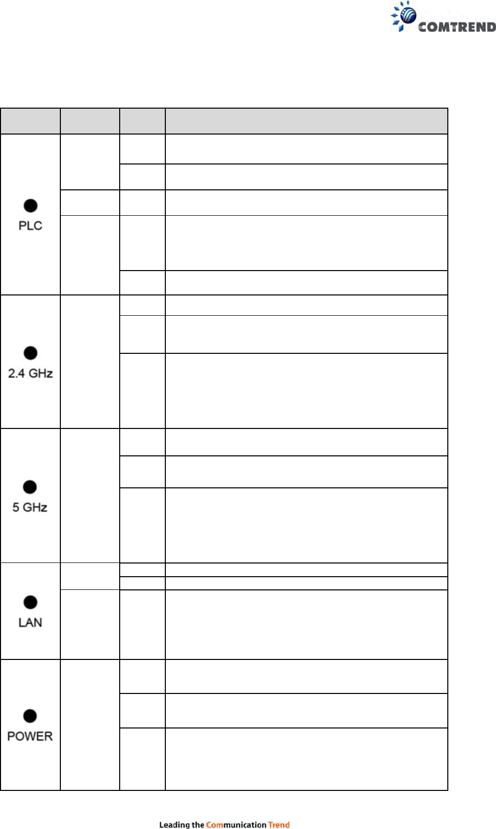
Chapter 3 LED Indications
LED COLOR MODE DESCRIPTION
Green On The current connection (line rate) is more than 40
Mbps
Blink (1). PLC pairing
(2). System rebooting
Orange On The current connection (line rate) is more than 20
Mbps and less than 40 Mbps
Red On
(1). The current connection (line rate) is between 1
and 20 Mbps per second)
(2). The PLC is in unsecure mode* and connected to
other PLCs
Off No PLC connection exists
Green
Off 2.4GHz WLAN is disabled
On 2.4GHz WLAN is on or activity occurring (tx/rx data
and message)
Blink
(1). Fast Blinking:
1.WPS SSID/Key sync copy failed
(2). Slow Blinking:
1. Normal WPS sync activity
2. WPS SSID/Key sync activity
3. System in Factory Reset process
Blue
Off 5GHz WLAN is disabled
On 5GHz WLAN is on or activity occurring (tx/rx data
and message)
Blink
(1). Fast Blinking:
1.WPS SSID/Key sync copy failed
(2). Slow Blinking:
1. Normal WPS sync activity
2. WPS SSID/Key sync activity
3. System in Factory Reset process
Green Off LAN Interface down
On LAN Interface up 10/100/1000
Orange
Blink
(1). Fast Blinking:
1. WPS SSID/Key sync copy failed
(2). Slow Blinking:
1. WPS SSID/Key sync activity
2. System in Factory Reset process
Green
Off System is powered off
On System is powered on
Blink
(1). Fast Blinking:
1. WPS SSID/Key sync copy failed
(2). Slow Blinking:
1. WPS SSID/Key sync activity
2. System in Factory Reset process
13
* Note: PG-9172AC does not support secured LED indication. If the PLC LED is RED in
deployment, it may indicate that the G.hn network is in unsecured mode. The user needs to
manually pair the PLC units to create a secure connection.
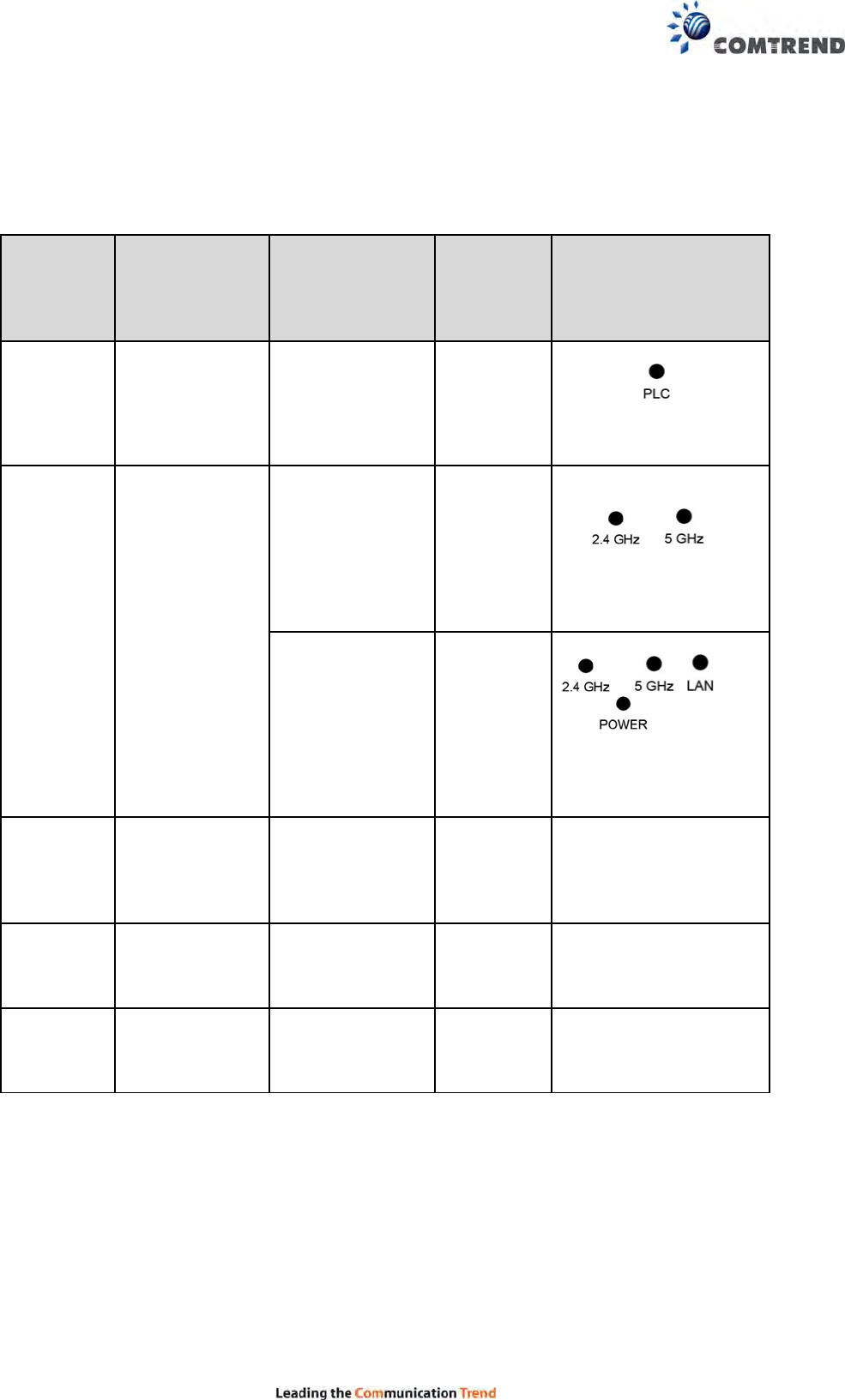
Chapter 4 Button Functions
BUTTON WORDING ON
ENCLOSURE BUTTON
FUNCTION
SECONDS
TO PUSH
BUTTON
DESCRIPTION
1 PLC Sync PLC pairing +2sec
Press more than 2
seconds ( LED
starts slow blinking),
and configuration
period is open
2 WPS
WPS 2-5 sec
1. Press for 2-5
seconds, and both
& LED
blink slowly.
2. Then release the
button, the AP WPS
is in process.
WiFi
SSID/PW copy +5 sec
Press for +5 seconds,
& , ,
and LED blink
slowly, the WLAN is in
sync with main
gateway for SSID
and Key on 2.4GHz
3 RESET Factory reset +10 sec
Press more than 10
seconds: a factory
reset of the system
(both G.hn & WiFi) is
performed
4 WiFi ON/OFF
Switch off/on
2.4GHz/5GHz
WiFi interfaces +2 sec
Disable/enable both
2.4G/5GHz WLAN
interfaces by pushing
the button for +2s
1&2 N/A
Switch off/on all
LED’s +2 sec
Turn on/off all LED’s by
pushing both PLC Sync
and WPS buttons
simultaneously for +2s

14
Chapter 5 wireless System and Network Setup
5.1 Connect to power line access point by web
browser
PG-9172AC supports two kinds of management IP.
(1) DHCP client, which gets a dynamic IP address from the
Modem/Broadband Router/Home Gateway that it is connected to by default.
(2) Static IP, 192.168.0.5 by default, which can be configurable in the web UI.
Before you can connect to the power line access point and start configuration procedures,
your computer must be able to get an IP address automatically (dynamic IP address).
PG-9172AC gets a dynamic IP address from Modem/Broadband Router/Home Gateway that
it is connected to by default. However, the current IP info of PG-9172AC would be
displayed at the Modem/Broadcom Router/Home Gateway.
Also, the static IP of PG-9172AC can be accessed by the default static IP address of
192.168.0.5, subnet mask 255.255.255.0. Change your PC’s static IP address to
291.68.0.100, subnet mask 255.255.255.0 for accessing web UI management.
15
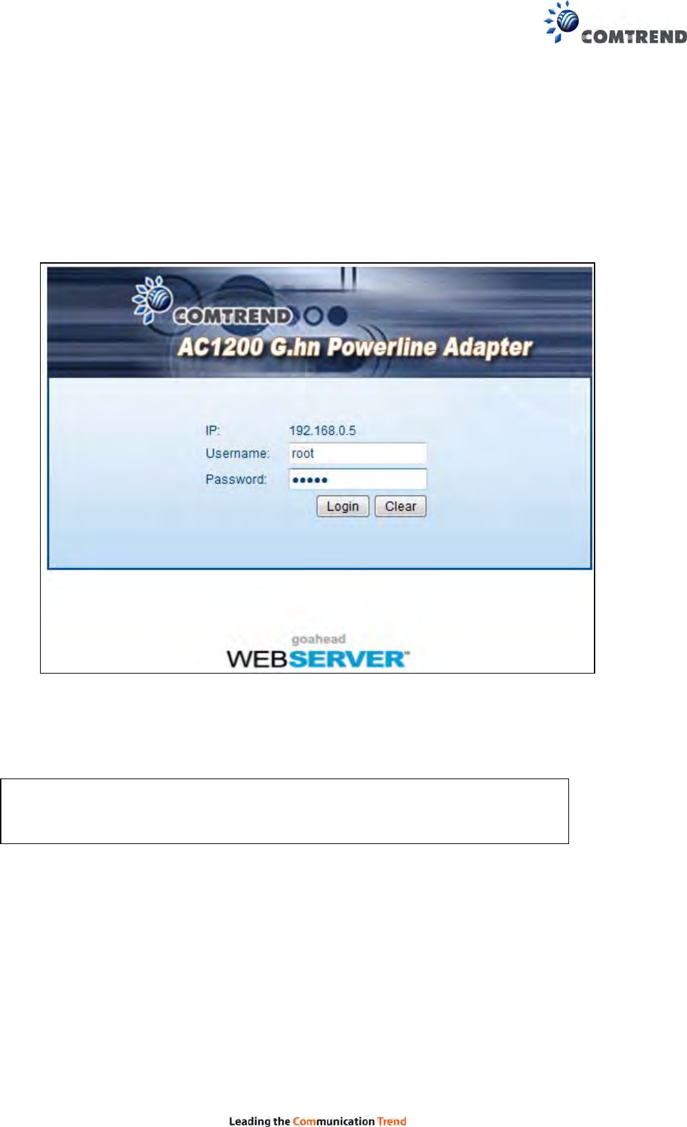
5.2 Connecting to Web Management Interface
All functions and settings for the Wi-Fi AP of PG-9172AC must be configured via the
web management interface. Please start your web browser, and input ‘192.168.0.5’in the
address bar, then press the ‘Enter’ key. The following will be displayed:
Please input user name and password in their respective fields, default user name is ‘root,
and default password is ‘12345, then press the Login button, to view the web management
interface of this access point.
NOTE: If you can’t see the web management interface, and you’re
being prompted to input user name and password again, it means you
didn’t input username and password correctly.
16
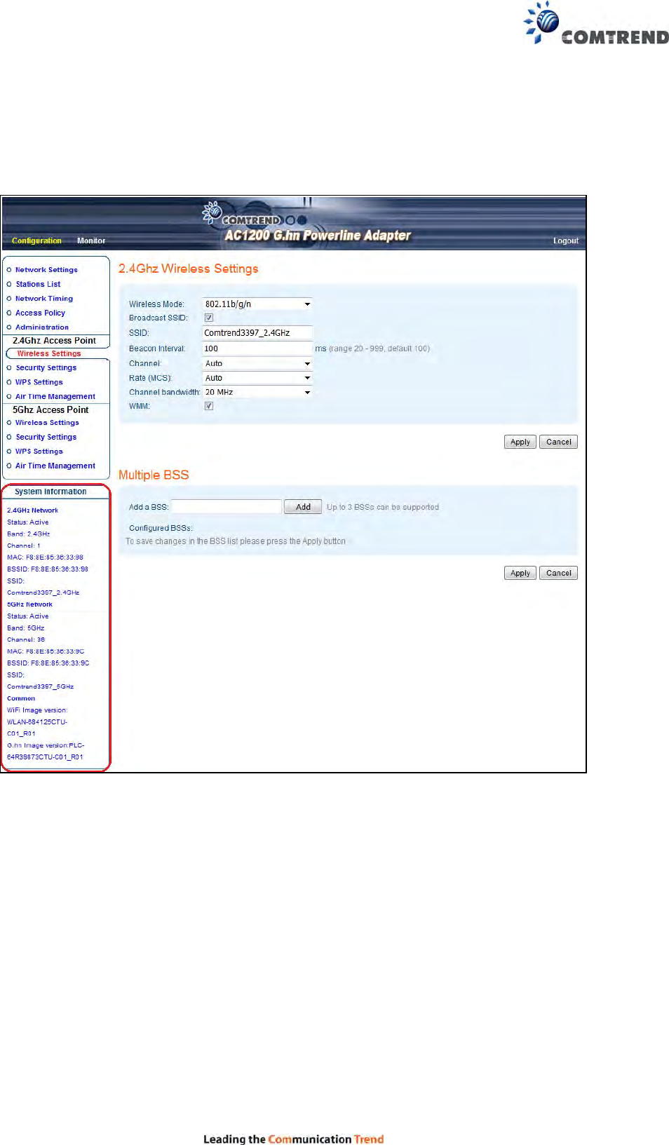
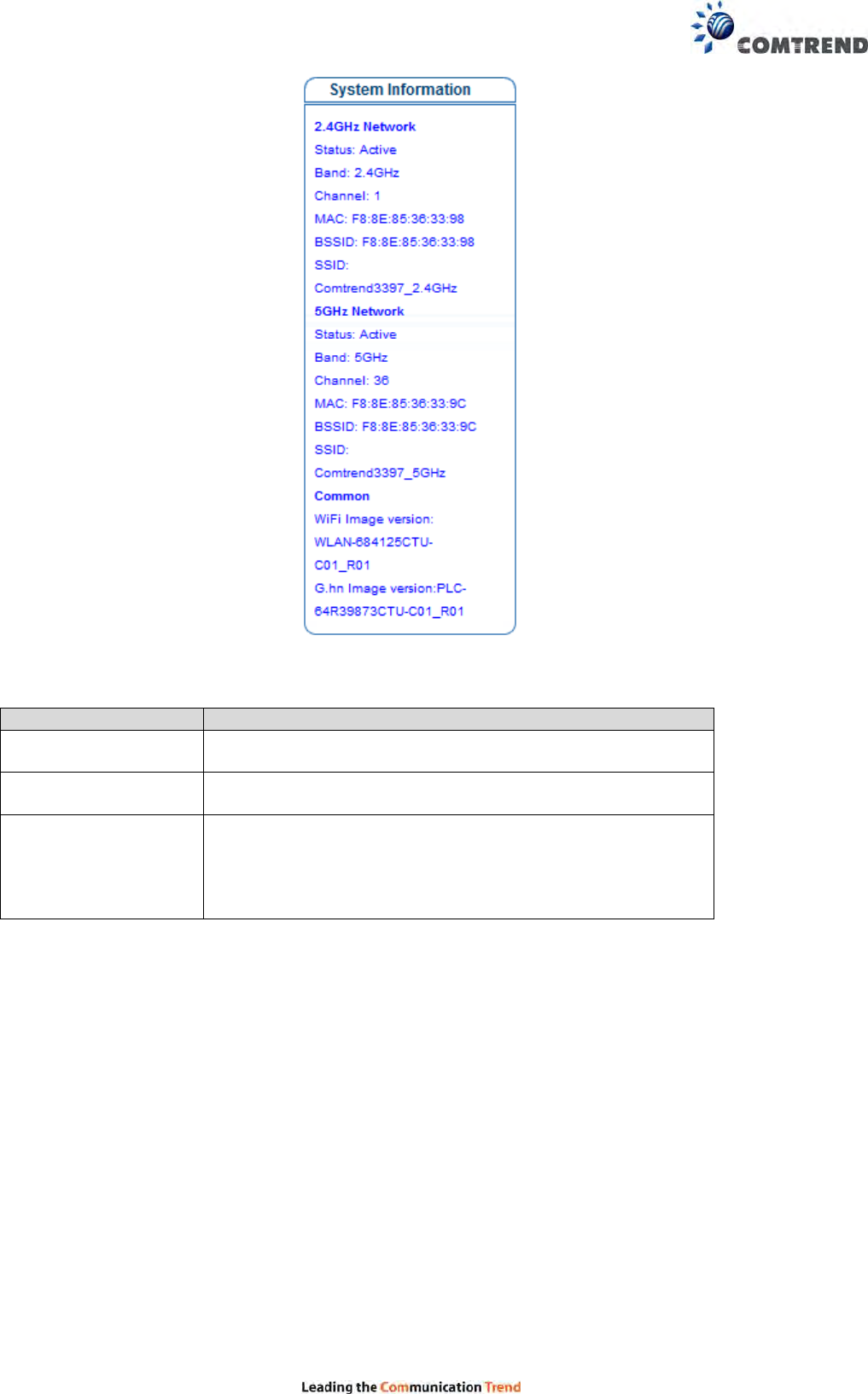
5.3 View System Information
The system information is on the left-side of the web page as shown below.
17
Here are descriptions of every item:
Heading Description
2.4GHz Network Displays 2.4GHz AP status, Channel, MAC, BSSID
and SSID string.
5GHz Network Displays 5GHz AP status, Channel, MAC, BSSID and SSID
string.
Common WiFi and G.hn Image version information.
WiFi Image version:
PG-9172AC-WLAN-684125CTU-C01_R01
G.hn Image version:
PG-9172AC-PLC-64R39873CTU-C01_R01
18
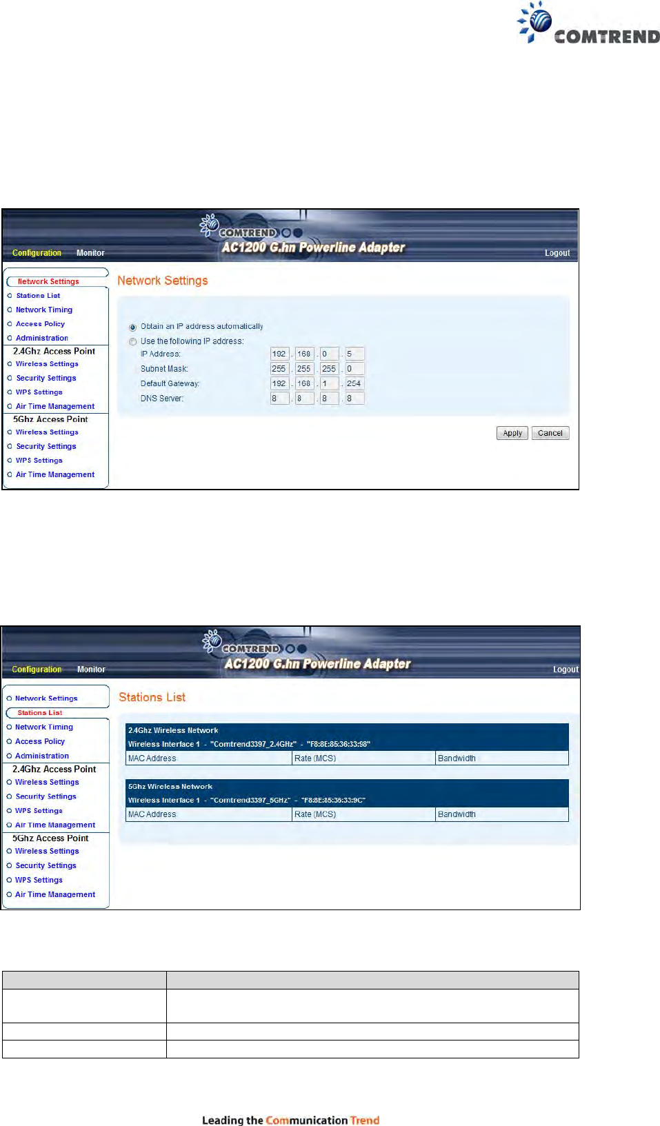
5.4 Network Settings
This page allows you to set the IP address for the web UI. Click the Apply button to reboot
the system and implement your changes.
5.5 Stations List
This is page shows the information of wireless Stations that are connected to PG-9172AC.
Here are descriptions of every item:
Heading Description
MAC address This option will list the Wireless stations connected to the
PG-9172AC at the 2.4G or 5GHz Interface.
Rate (MCS) MCS# on the wireless interface with the station.
Bandwidth Bandwidth, 20/40MHz for 2.4GHz, 20/40/80MHz for 5GHz
19
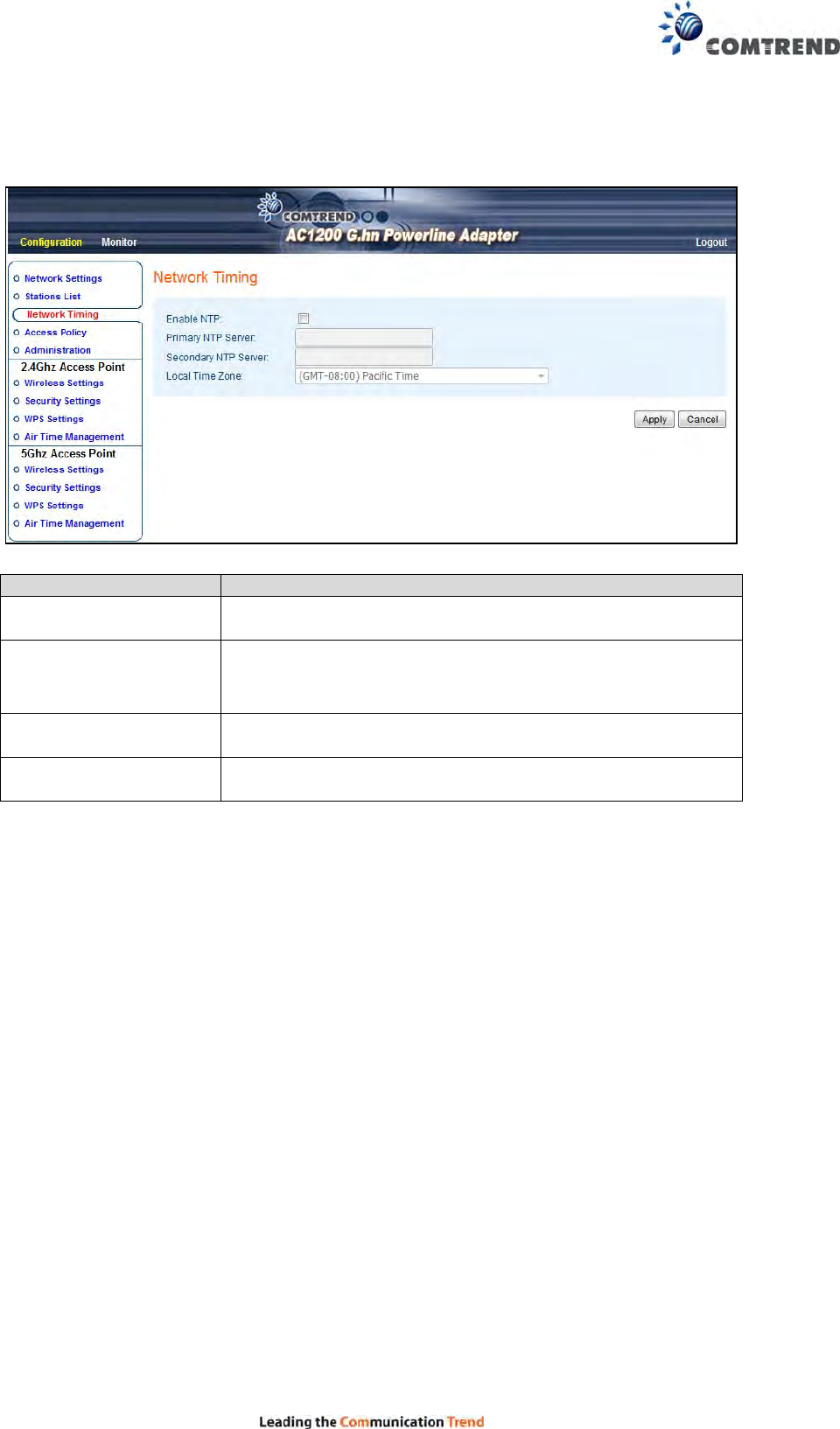
5.6 Network Timing
This page allows you to set the local time zone for TR069 management.
Heading Description
Enable NTP You can decide to set up NTP client by clicking checkbox.
Primary NTP Server Input the Primary NTP Server, for example:
us.pool.ntp.org, etc.
Secondary NTP Server Input the Secondary NTP Server, for example:
wwv.nist.gov
Local Time Zone You can select your Time Zone from the drop-down menu.
20
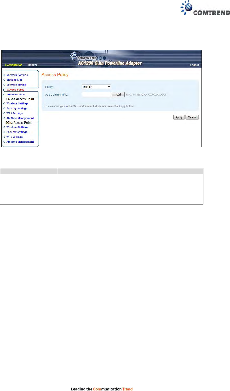
5.7 Access Policy
This page allows you to set the Access Policy for a specific MAC address.
Here are descriptions of every item:
Heading Description
Policy: This option will allow/reject the list of wireless stations.
Add a station MAC MAC format is XX:XX:XX:XX:XX:XX
A maximum of 32 entries can be configured.
To save changes in the MAC addresses list press the Apply button.
21
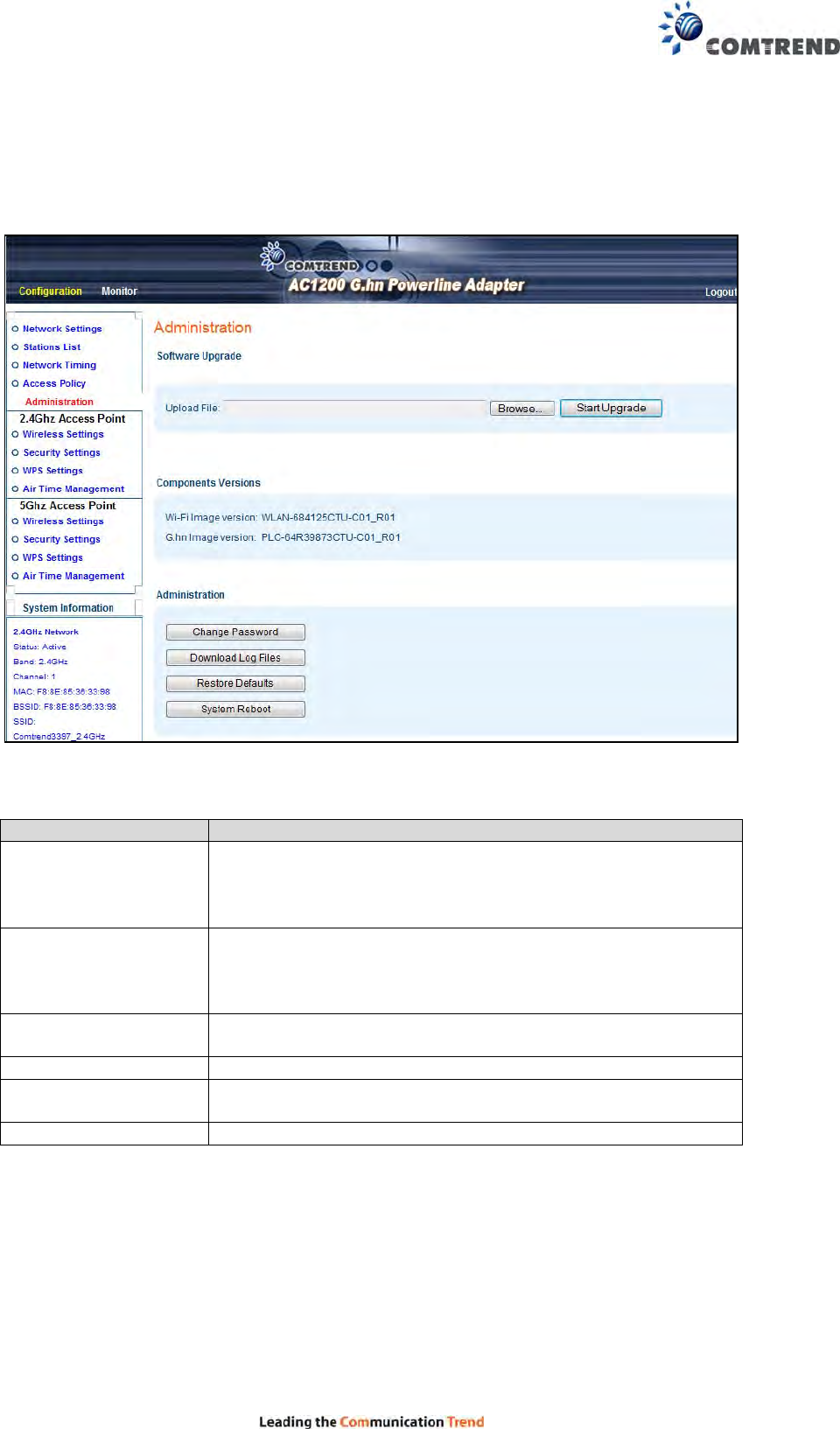
5.8 Administration
This page allows you to upgrade the software, view the components versions, change the
password, download log files, restore defaults or reboot the system.
Here are descriptions of every setup item:
Heading Description
Software Upgrade
Select the firmware file for the PG-9172AC from the local
driver of your laptop.
*PLC firmware can be updated via Marvell’s SCT tool locally
or via TR069 protocol remotely.
Components Versions Wi-Fi Image version:
PG-9172AC-WLAN-684125CTU-C01_R01
G.hn Image version:
PG-9172AC-PLC-64R39873CTU-C01_R01
Change Password Click this button to change the password (Only for “admin”
account)
Download Log Files Reserved for debugging purpose
Restore Defaults Click this button to reset all the settings of PG-9172AC to
their factory defaults (Wi-Fi & G.hn PLC)
System Reboot Click this button to restart the PG-9172AC
22
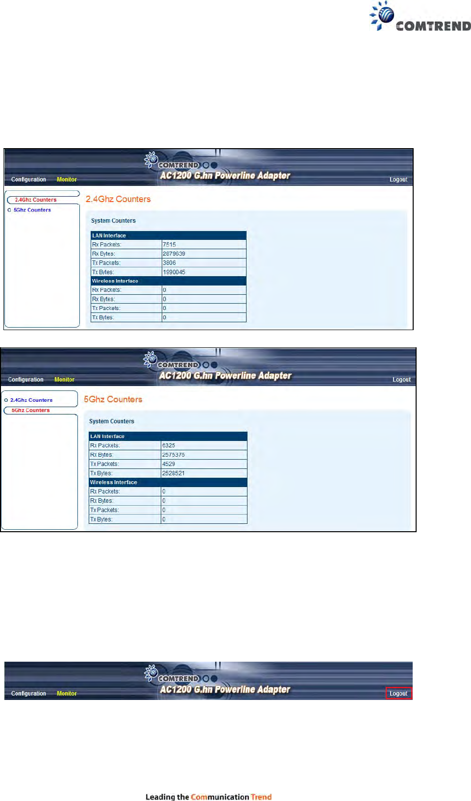
5.9 Monitor
This page shows the statistics on LAN, 2.4G & 5G interfaces.
5.10 Logout
Log out from the web management.
23
Chapter 6 Wireless Configurations
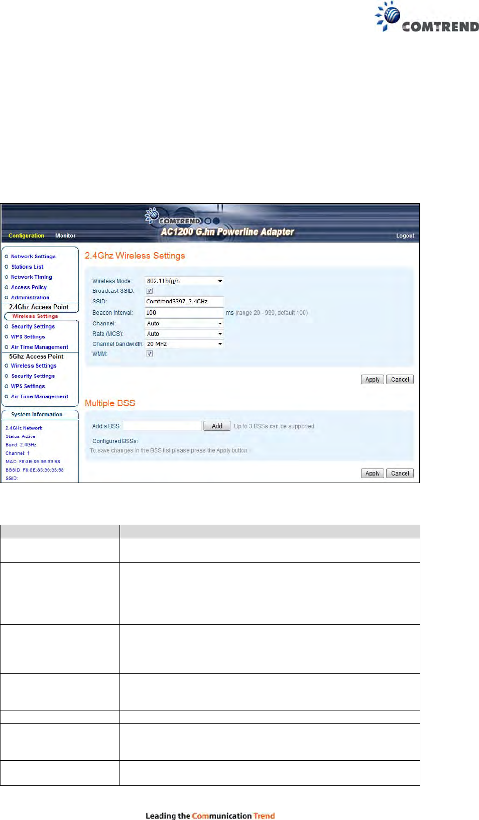
6.1 2.4G Wireless Settings
This page allows you to configure the basic settings for the 2.4GHz interface of the access
point.
Here are descriptions of every setup item:
Heading Description
Wireless Mode 802.11b/g legacy: auto selection of 802.11b/g.
802.11b/g/n: auto selection of 802.11b/g/n
Broadcast SSID Decide if the wireless power line access point will
broadcast its own SSID or not. You can hide the SSID of
your wireless power line access point (set the option to
‘Disable’), so only those who know the SSID of your
wireless power line access point can get connected.
SSID Please input the SSID (the name used to identify this
wireless access point) here. You can input up to 32
alphanumerical characters. PLEASE NOTE THAT THE
SSID IS CASE SENSITIVE.
Beacon Interval The default is 100 ms and the acceptable range is 20 –
999(ms). It’s safe to keep the default and it’s not
necessary to change unless you know the effect.
Channel Select Auto, Or manually select a channel.
Rate(MCS) Modulation and Coding Scheme. It’s safe to select Auto
and it’s not necessary to change unless you know the
effect.
Channel Bandwidth Select the wireless channel width by drop-down
menus(bandwidth taken by wireless signals of this access
24
point).
20MHz : lower performance but less interference.
40MHz : Auto 40/20MHz(automatically select based on
interference level)
WMM WMM (Wi-Fi Multimedia) technology, can improve the
performance of certain network applications, like
audio/video streaming, network telephony (VoIP),
and others. When you enable the WMM function, the
power line access point will define the priority of different
kinds of data, to give higher priority to applications which
require an instant response. Therefore you can improve
the performance of such network applications.
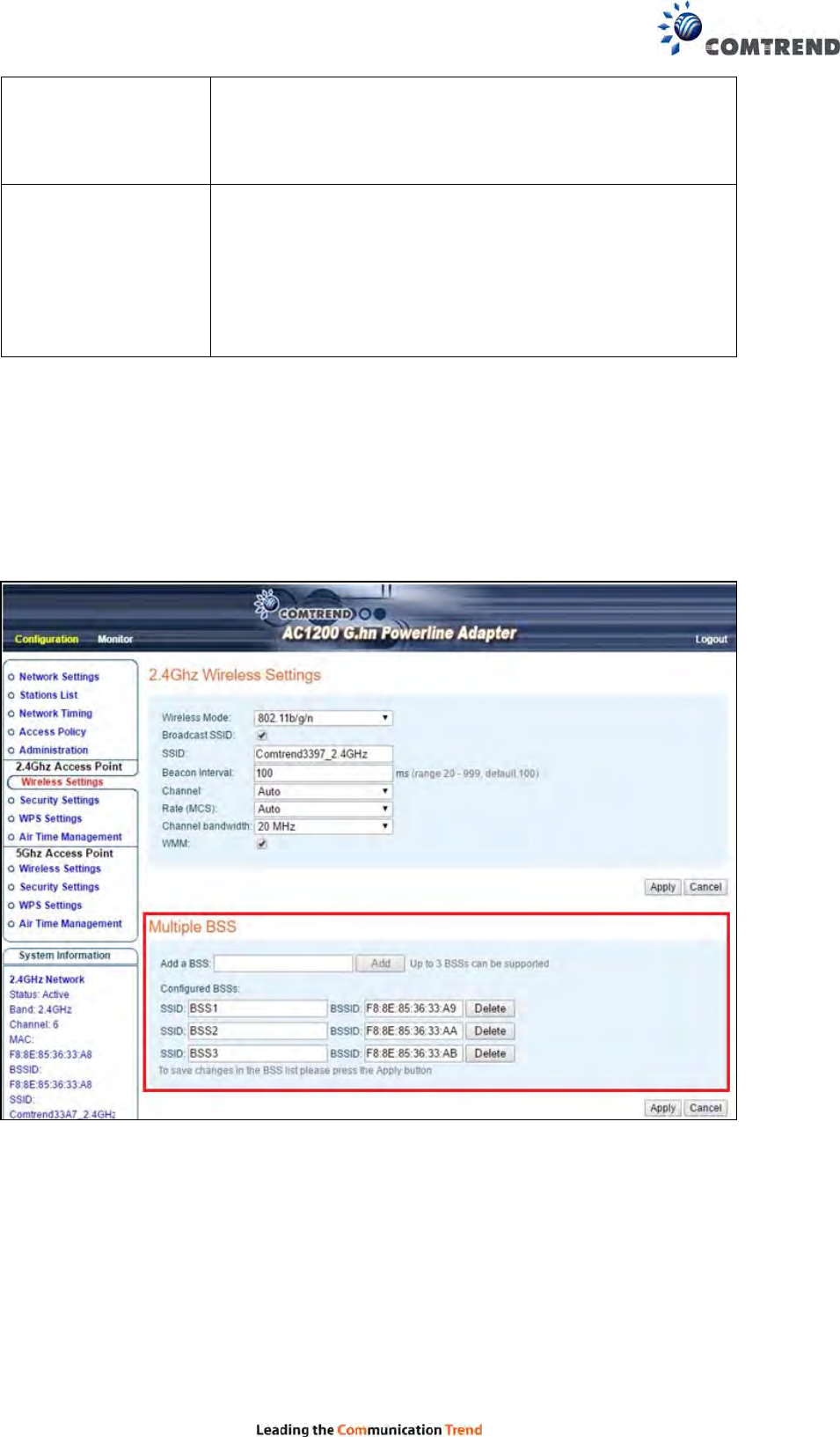
6.1.1Multiple BSS
A BSS, Basic Service Set consists of all the devices associated with an IEEE 802.11 wireless
local area network (WLAN).
This section allows you to add up to 3 additional BSSIDs (Basic Service Set Identifiers) for
the 2.4GHz interface of the access point.
To save changes in the BSS list click the Apply button.
25
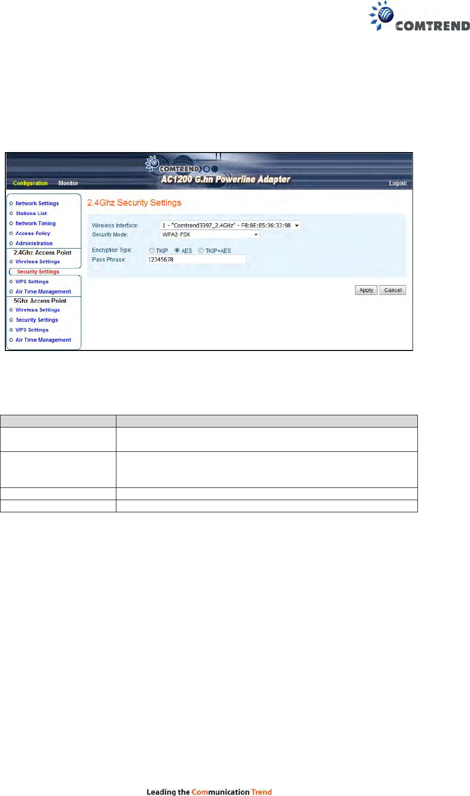
6.2 2.4G Security Settings
This page allows you to configure the Security Settings for 2.4Ghz interface of the access
point.
Click the Apply button to save your settings.
Here are descriptions of every setup item:
Heading Description
Wireless Interface Select the interface that you want to configure from the
SSID or the BSSs you have added.
Security Mode Select the encryption supported over wireless access. The
encryption method can be Disabled/None, WPA-PSK,
WPA2-PSK or WPA-PSK+WPA2-PSK.
Encryption Type There are three types of Cipher: TKIP, AES, TKIP+AES
Pass Phrase 8 to 63 alphanumerical characters
26
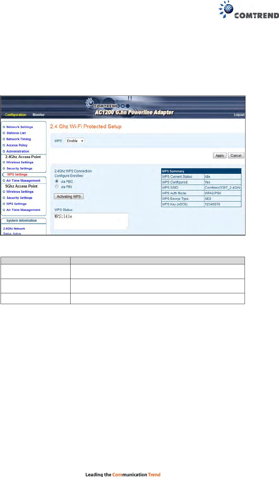
6.3 2.4G WPS Settings
This page allows you to configure the WPS Settings for 2.4Ghz interface of the access point.
Wi-Fi Protected Setup allows that each time you want to set up a connection, there is no
need to select the encryption mode and enter the encryption password.
Heading Description
WPS Select to Enable/Disable WPS from the drop-down menu.
Then click the Apply button to implement your selection.
Configure Enrollee Select between via PBC (Push Button Control) and via PIN
(Personal Identification Number)
WPS Status Shows the current WPS status
Click the Activating WPS button to confirm your choice.
27
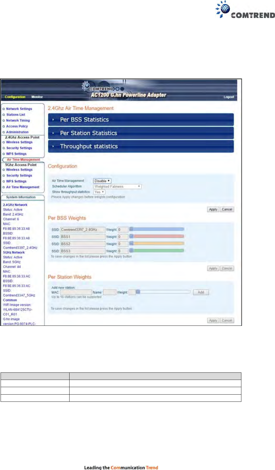
6.4 2.4G Air Time Management
This page allows you to configure the setting for Air Time Management of the 2.4GHz
Access Point.
6.4.1 2.4Ghz Air Time Management
This part shows the Statistics of BSS, Station or throughput.
Heading Description
Per BSS Statistics Displays each BSS’s statistics
Per Station Statistics Displays each Station’s statistics
Throughput Statistics Displays all statistics
28
6.4.2 Configuration
This part allows you to set up the Air Time Management, select the Scheduler Algorithm
and whether show throughput statistics or not.
Heading Description
Air Time Management Select to Enable/Disable Air Time Management from the
drop-down menu.
Scheduler Algorithm Select to No
Fairness(Round Robin)/Fairness/Weighted Fairness
Scheduler Algorithm from the drop-down menu,
No Fairness(Round Robin) :
The order will decide the transmission, so the longer the
device is connected, the longer the wait time.
Fairness:
Each device occupies the same transmission time.
Weighted Fairness :
According to the Weight you give will decide the priority of
transmission.
Show Throughput
Statistics Select to YES/NO to Show Throughput Statistics.
Click the Apply button to implement your changes.
6.4.3 Per BSS Weights
This part allows you to configure each BSS’s Weight from 0 to 100, the higher the Weight
you give, the more priority it has.
To save changes in the list click the Apply button.
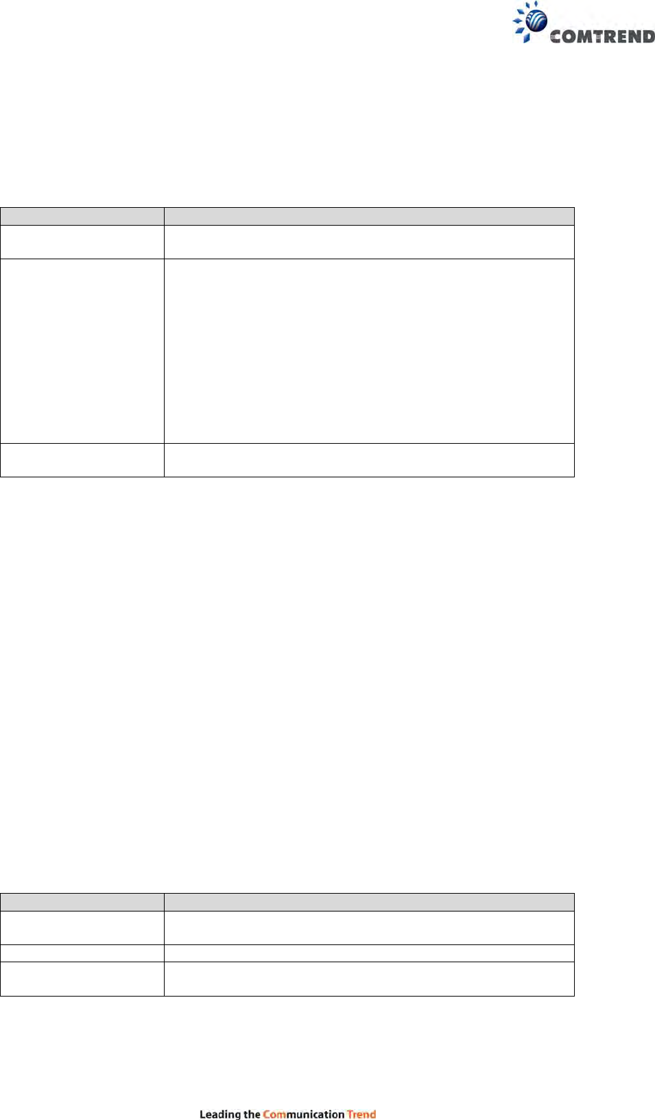
6.4.4 Per Station Weights
This part allows you to configure each WiFi station’s Weight from 0 to 100, the higher the
Weight you give, the more priority it has.
Heading Description
MAC Input the MAC address from the device which you want to
add on.
Name Input an ID for the station (Reserved)
Weight Set the Weights for the Station from 0 to 100 by scrolling
the scroll or Input number.
Click the Add button to create the new entry. Click the Delete button to remove an entry. To
save changes in the list, click the Apply button.
29
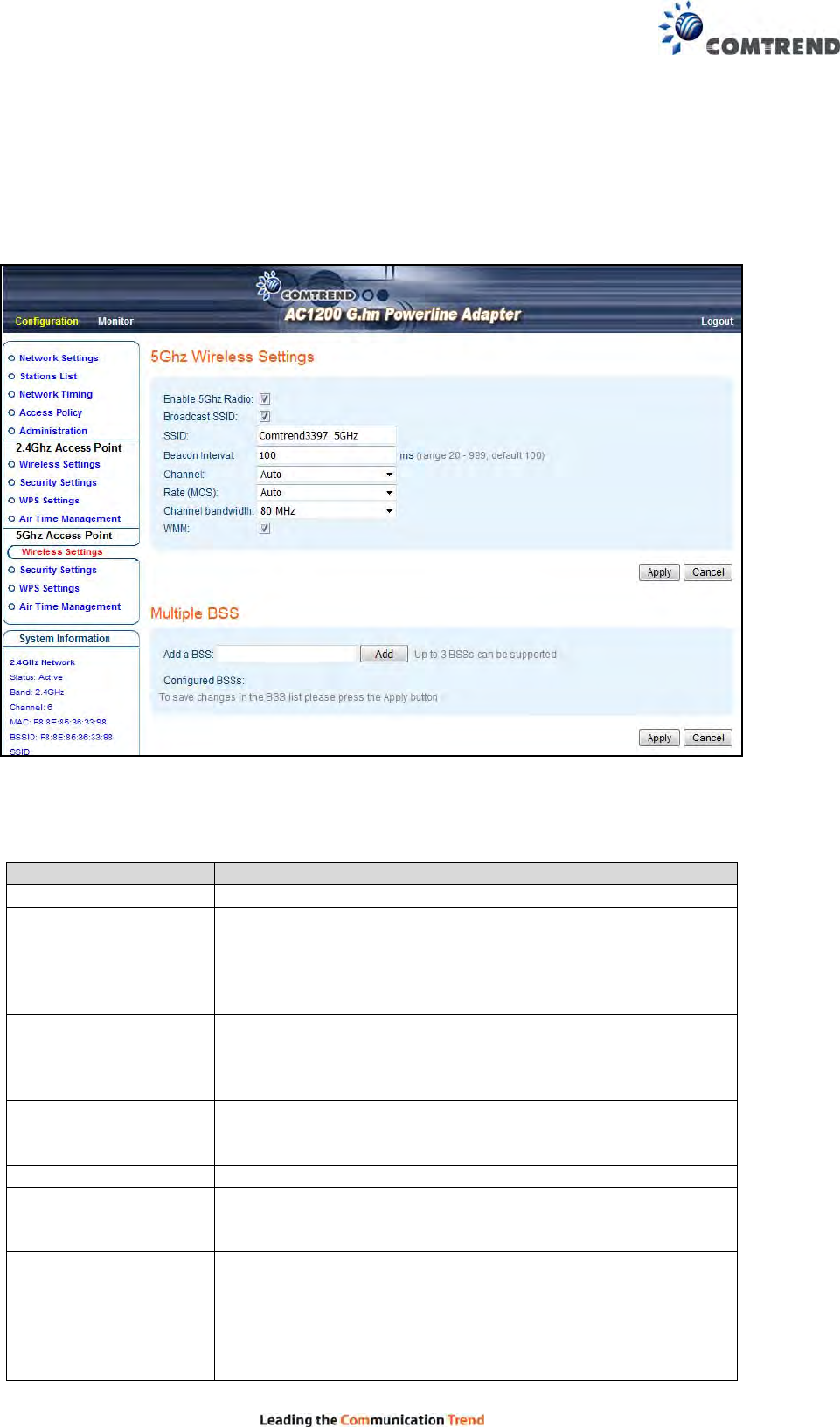
6.5 5G Wireless Settings
This page is to configure basic settings for the 5GHz interface of the access point.
Here are descriptions of every setup item:
Heading Description
Enable 5Ghz Radio Tick to enable 5GHz radio.
Broadcast SSID Decide if the wireless power line access point will
broadcast its own SSID or not. You can hide the SSID of
your wireless power line access point (set the option to
‘Disable’), so only those who know the SSID of your
wireless power line access point can get connected.
SSID Please input the SSID (the name used to identify this
wireless access point) here. You can input up to 32
alphanumerical characters. PLEASE NOTE THAT THE
SSID IS CASE SENSITIVE.
Beacon Interval The default is 100 ms and the acceptable range is 20 –
999(ms). It’s safe to keep in default and it’s not necessary
to change unless you know the effect.
Channel Select Auto, Or manually select a channel.
Rate(MCS) Modulation and Coding Scheme. It’s safe to select Auto
and it’s not necessary to change unless you know the
effect.
Channel Bandwidth Select wireless channel width from the drop-down
menu(bandwidth taken by wireless signals of this access
point).
20MHz : lower performance but less interference.
40MHz : Auto 40/20MHz
30
80MHz : Auto 80/40/20MHz
(automatically select based on interference level)
WMM WMM (Wi-Fi Multimedia) technology, can improve the
performance of certain network applications, like
audio/video streaming, network telephony (VoIP),
and others. When you enable the WMM function, the
power line access point will define the priority of different
kinds of data, to give higher priority to applications which
require an instant response. Therefore you can improve
the performance of such network applications.
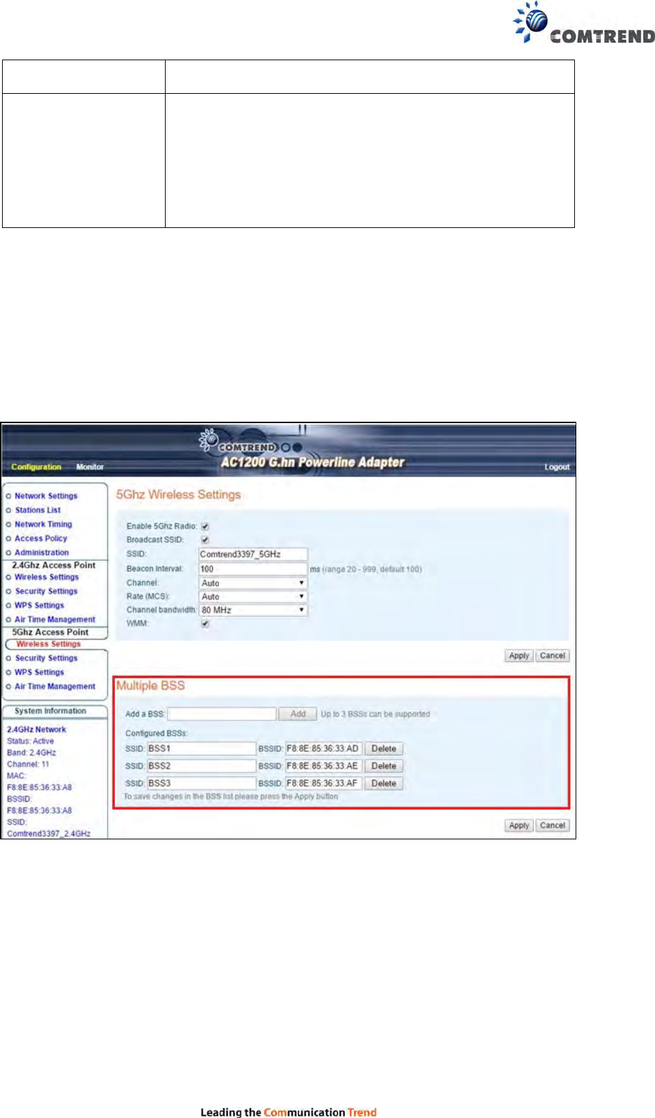
6.5.1 Multiple BSS
A BSS, Basic Service Set consists of all the devices associated with an IEEE 802.11 wireless
local area network (WLAN).
This section allows you to add up to 3 additional BSSIDs (Basic Service Set Identifiers) for
the 5GHz interface of the access point.
To save changes in the BSS list click the Apply button.
31
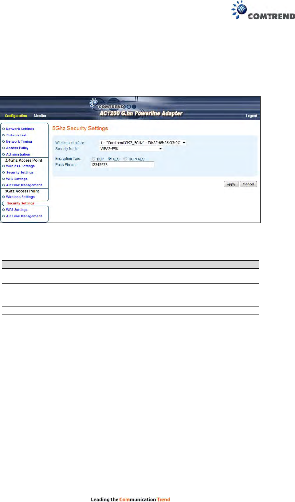
6.6 5G Security Settings
This page allows you to configure the Security Settings for the 5Ghz interface of the access
point.
Here are descriptions of every setup item:
Heading Description
Wireless Interface Select the interface that you want to configure from the
SSID or the BSSs you have added.
Security Mode Select the encryption supported over wireless access. The
encryption method can be Disabled/None, WPA-PSK,
WPA2-PSK or WPA-PSK+WPA2-PSK.
Encryption Type There are three types of Cipher: TKIP, AES, TKIP+AES
Pass Phrase 8 to 63 alphanumerical characters.
32
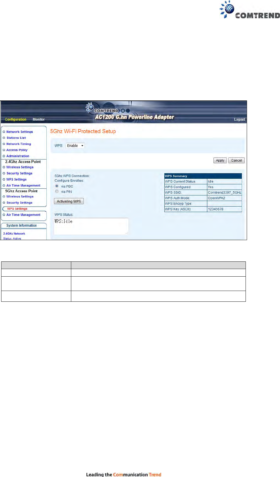
6.7 5G WPS Settings
This page allows you to configure the WPS Settings for the 5Ghz interface of the access point.
Wi-Fi Protected Setup means that each time you want to set up a connection, there is no
need to select the encryption mode and enter the encryption password.
Heading Description
WPS Select to Enable/Disable WPS from the drop-down menu.
Configure Enrollee Select between via PBC (Push Button Control) and via PIN
(Personal Identification Number)
WPS Status Shows the current WPS status
Click the Activating WPS button to confirm your choice.
33
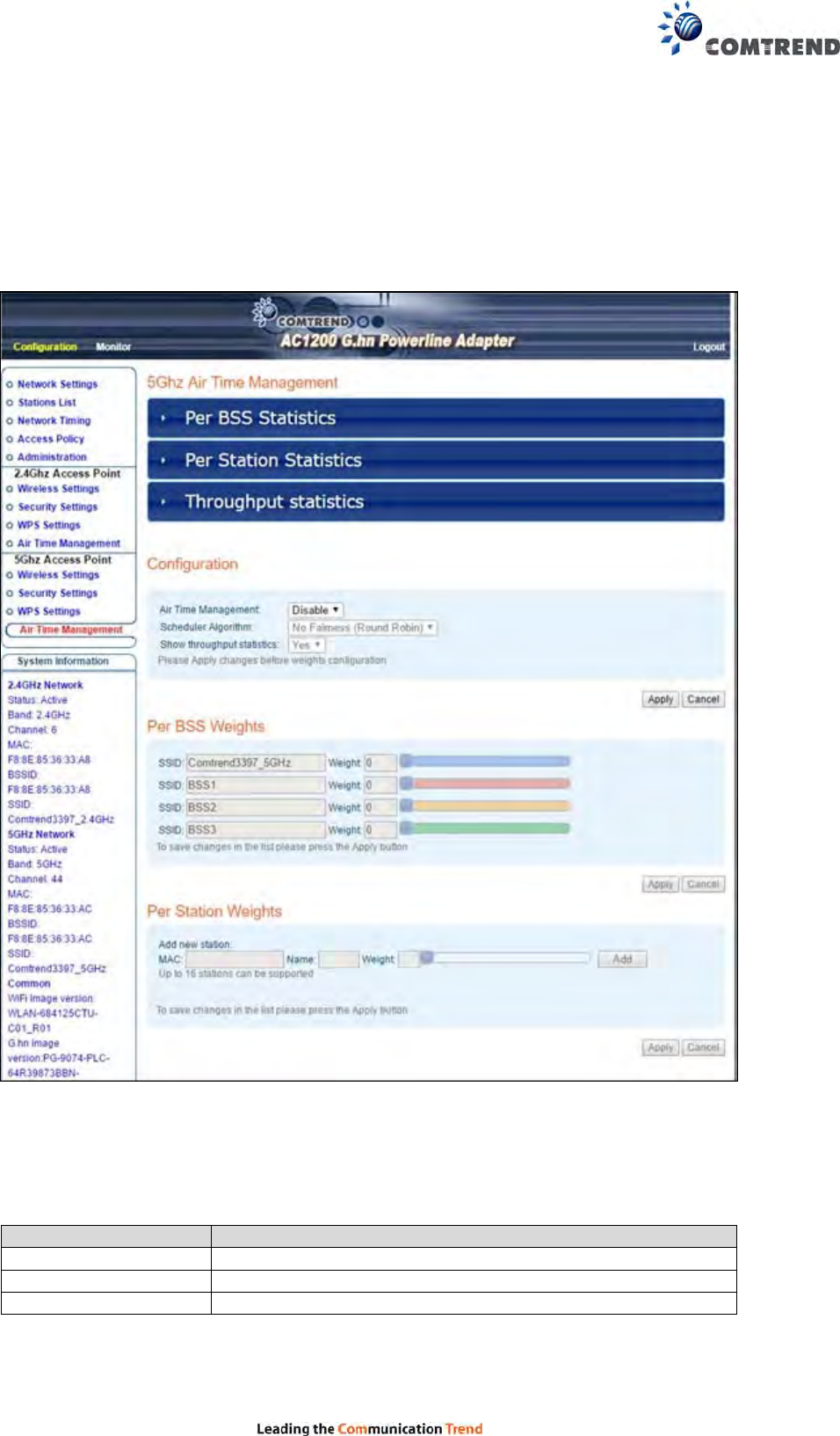
6.8 5G Air Time Management
This page allows you to configure the setting for Air Time Management of 5GHz Access Point.
6.8.1 5Ghz Air Time Management
This part shows the Statistics of BSS, Station or throughput.
Heading Description
Per BSS Statistics Displays each BSS’s statistics
Per Station Statistics Displays each Station’s statistics
Throughput Statistics Display all statistics
34
6.8.2 Configuration
This part allows you to set up the Air Time Management, select the Scheduler Algorithm
and whether to show throughput statistics or not.
Heading Description
Air Time Management Select to Enable/Disable Air Time Management from the
drop-down menu.
Scheduler Algorithm Select to No
Fairness(Round Robin)/Fairness/Weighted Fairness
Scheduler Algorithm from the drop-down menu,
No Fairness(Round Robin) :
The order will decide the transmission, so the longer the
device is connected, the longer the wait time.
Fairness:
Each device occupies the same transmission time.
Weighted Fairness :
According to the Weight you give will decide the priority of
transmission.
Show Throughput
Statistics Select to YES/NO to Show Throughput Statistics.
Click the Apply button to implement your changes.
6.8.3 Per BSS Weights
To save changes in the list click the Apply button.
6.8.4 Per Station Weights
This part allows you to configure each WiFi Station’s Weight from 0 to 100, the higher the
Weight you give, the more priority it has.
Heading Description
MAC Input the MAC address from the device which you want to
add on.
Name Input an ID for the station (Reserved)
Weight Set the Weights for Station from 0 to 100 by scrolling the
scroll or Input number.
Click the Add button to create the new entry. Click the Delete button to remove an entry.
35
Chapter 7 G.hn/Powerline Setup
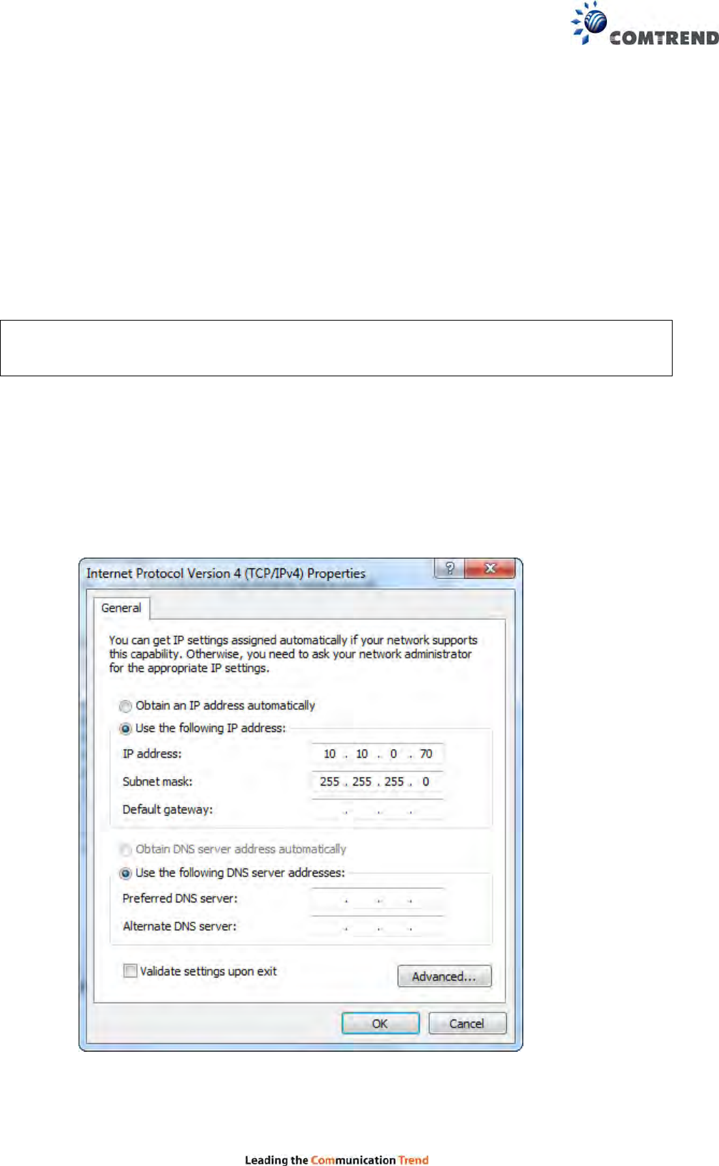
7.1 Configure STATIC IP MODE
In static IP mode, you assign IP settings to your PC manually.
Follow these steps to configure your PC IP address to use subnet 10.10.1.x.
NOTE: The following procedure assumes you are running Windows XP. However, the
general steps involved are similar for most operating systems (OS). Check your
OS support documentation for further details.
STEP 1: From the Network Connections window, open Local Area Connection (You may also
access this screen by double-clicking the Local Area Connection icon on your
taskbar). Click the Properties button.
STEP 2: Select Internet Protocol (TCP/IP) and click the Properties button.
STEP 3: Change the IP address to the domain of 10.10.1x (70<x<255) with subnet mask of
255.255.255.0. The screen should now display as below.
STEP 4: Click OK to submit these settings.
36
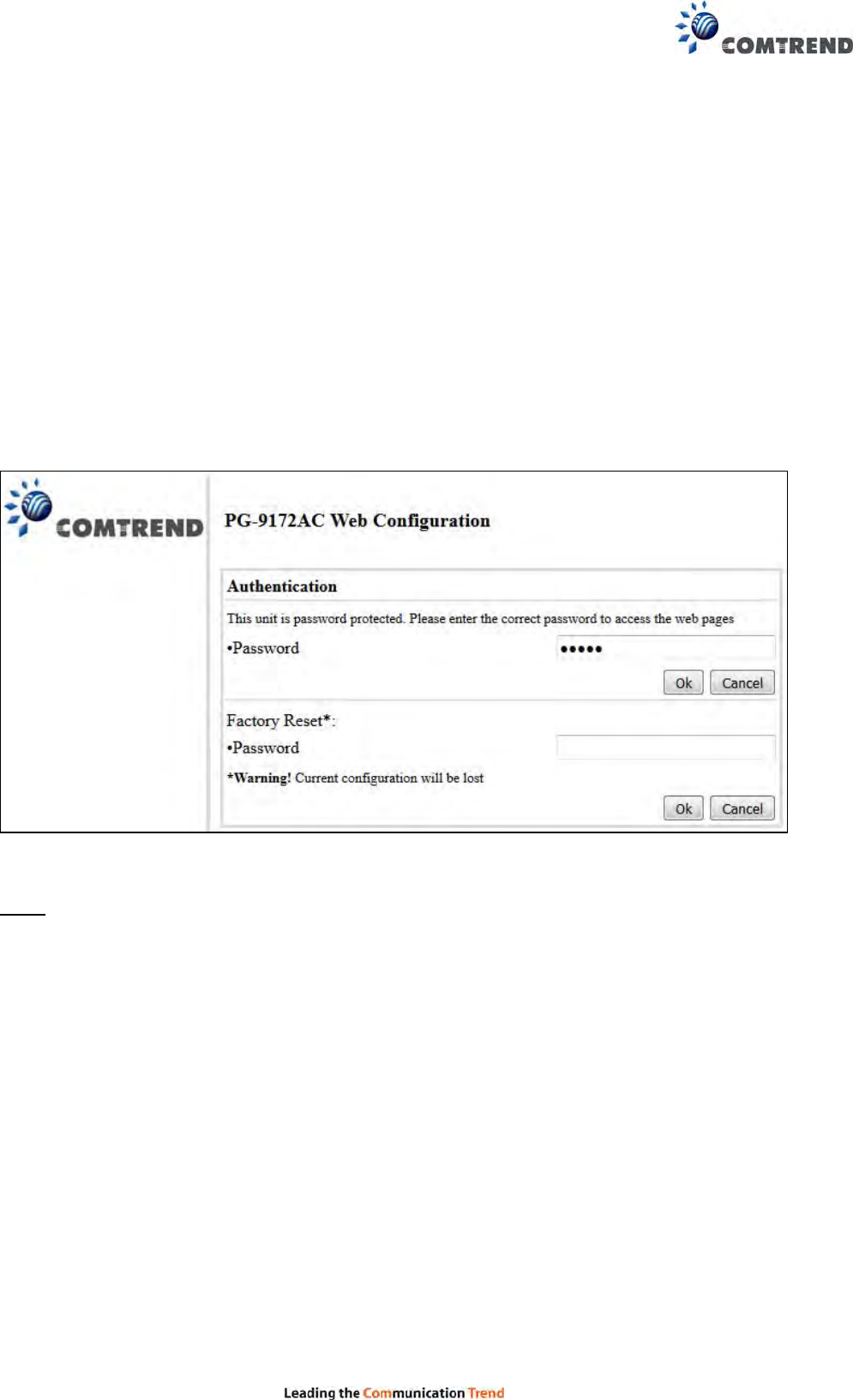
7.2 Logging In
Perform the following steps to login to the web user interface.
STEP 1: Start the Internet browser and enter the default IP address for the device in the
Web address field. For example, if the default IP address is 10.10.0.69, type
http://10.10.0.69
STEP 2: A dialog box will appear, such as the one below. Input the default Authentication
Password.
Authentication Password: admin
Click OK to continue.
Note:
The Factory Reset password is: betera
37
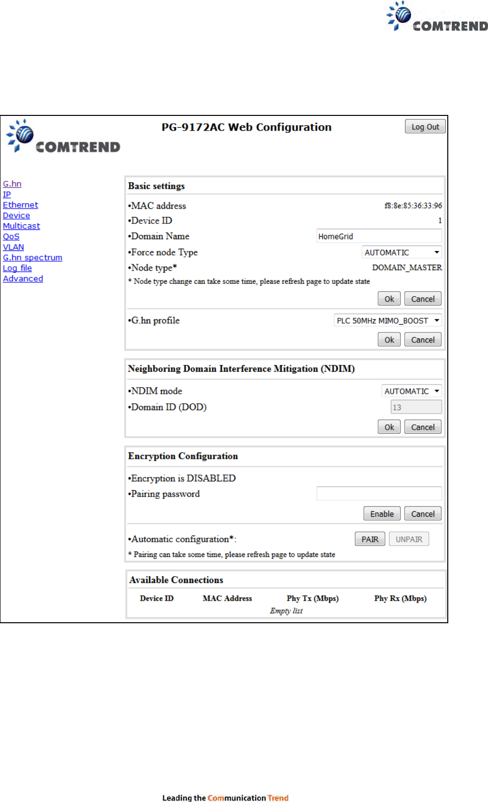
7.3 G.hn Interface

38
7.3.1 Basic Configuration
MAC Address Displays the MAC address of the device.
Device ID Device ID of this node.
Domain Name string of all nodes in the network.
Force node Type force the modem to have a particular role (END POINT or DOMAIN
MASTER)
G.hn profile of all nodes in the network: selecting which G.hn profile must be
applied to the network (PLC 50MHz, PLC 50MHz with MIMO, PLC 100MHz, COAX
100MHz and PHONE 100MHz).
7.3.2 NDIM Configuration
NDIM mode set to Automatic for enabling automatic DOD selection functionality
and set to Manual for manual configuration of DOD.
Domain ID (DOD) manually set the DOD number from 1 to 15 to use a different
preamble seed than the default 13.
7.3.3 Encryption Configuration via WEB UI
Pairing Password used for authentication. Write a custom password to
manually create a secure domain.
Available Connections
In this tab table, all the available G.hn connections are presented. Remote node
DID and MAC address, transmission and reception physical speeds.
39
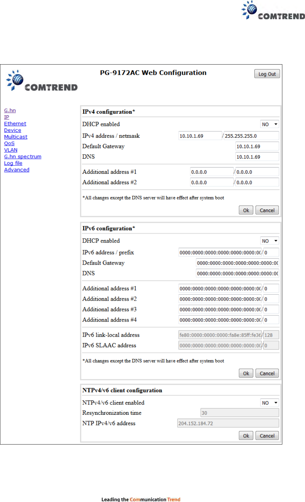
7.4 IP Interface

40
7.4.1 IP config
In the IP configuration tab of one G.hn node, the IPv4 and IPv6 settings can be
read and changed.
IPv4 subsection:
DHCPv4 enabled: in the case of choosing ”NO" IP configuration in the following
parameters, the IPv4 Address, Subnet Mask, Default Gateway and DNS
should be configured; fill these fields in. In the case of choosing “YES” they will be
filled automatically when configuration is received from the DHCPv4 server.
IPv4 address/netmask: IPv4 address / netmask of this device.
Default Gateway: IPv4 gateway to connect the device to other LAN segments.
DNS: Domain Name Server IP (IPV4).
Additional address #1/2: additional fixed IPv4 addresses that will always
be configured at boot time.
IPv6 subsection:
DCHPv6 enabled: in the case of choosing ”NO" IP configuration in the following
parameters, the IPv6 Address, prefix, Default Gateway and DNS should be configured;
fill these fields in. In the case of choosing “YES” they will be filled automatically
when configuration is received from the DHCPv6 server.
IPv6 Address / prefix: IPv6 address / prefix of the device to read the node's DHCPv6
address in case the DHCPv6 is enabled.
Default Gateway: IPv6 gateway to connect the node to other LAN segments.
DNS: Domain Name Server IP (IPV6).
Additional address #1/2/3/4: additional fixed IPv6 addresses that will always
be configured at boot time.
IPv6 Link-Local Address: to read the node's Link Local address.
IPv6 SLAAC address: IPv6 address, automatically obtained by means of the SLAAC
mechanism.
NTPv4/v6 subsection:
NTPv4/v6 client enabled: Enable/disable NTP client.
Resynchronization time: Configure re-synchronization interval time in minutes.
NTP IPv4/v6 address: Hostname or IP (IPv4 or IPv6) of NTP server.
41
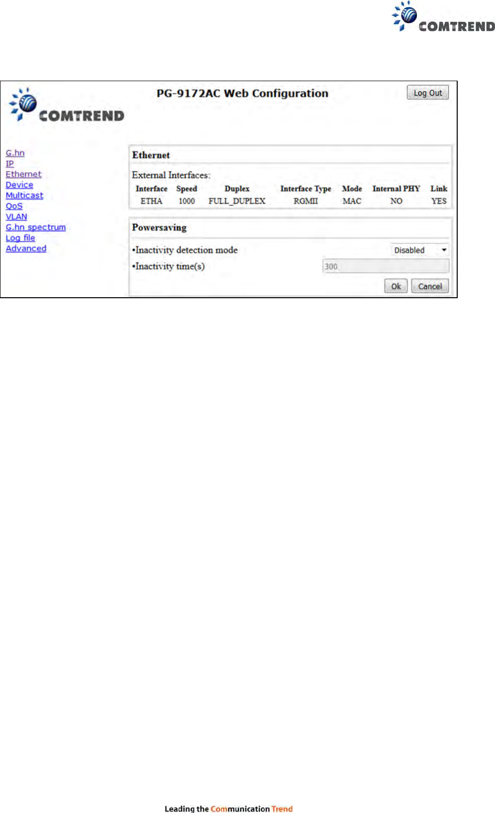
7.5 Ethernet Interface
The Ethernet table shows the coverage & Info of the Ethernet interface; including Interface,
Speed, Duplex, Interface Type, Mode, Internal PHY & Link.
Powersaving
Ethernet powersaving can be disabled, enabled by Ethernet link or enabled by Ethernet
activity; idle timer can be configured as well.
42
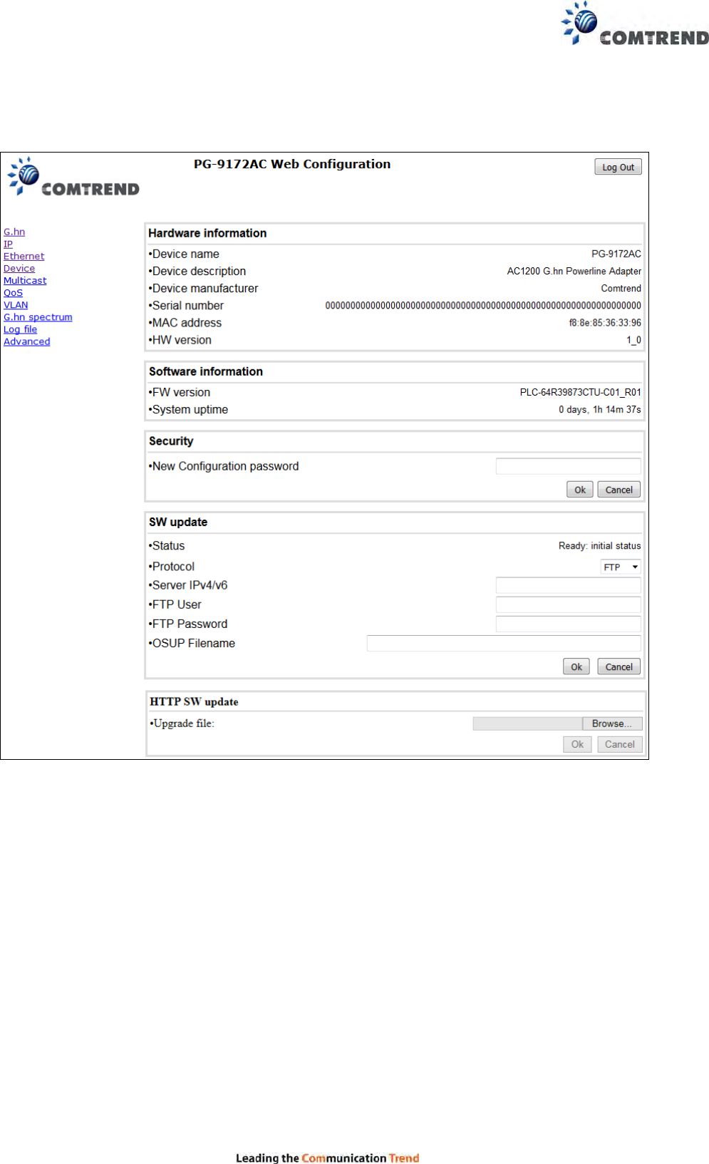
7.6 Device Interface
7.6.1 Hardware information
In this tab, basic information such as MAC Address and Serial Number of the selected node is
shown.
7.6.2 Software information
Shows the FW version and system uptime.

43
7.6.3 Security
The nodes in the network: to change the configuration password string from the default
("admin") to another; decided by the user.
7.6.4 SW update
Current loaded firmware version is shown. Any flash section can be upgraded; the first flash
section should be selected and after clicking on the "OK" button the corresponding file
should be chosen. Usually, a reboot should be performed afterwards to make sure
the changes are effective.
The protocol is by FTP client or TFTP client. L2 is proprietary and is reserved for future use.
7.6.5 HTTP SW update
STEP 1: Enter the path and filename of the firmware image file in the Software File Name
field or click the Browse button to locate the image file.
STEP 2: Click the OK button once to upload and install the file.
NOTE: The update process will take about 2 minutes to complete. The device will reboot
and the browser window will refresh to the default screen upon successful
installation. It is recommended that you compare the Software Version on the
Device Interface screen with the firmware version installed, to confirm the
installation was successful.
44
7.7 Multicast Interface
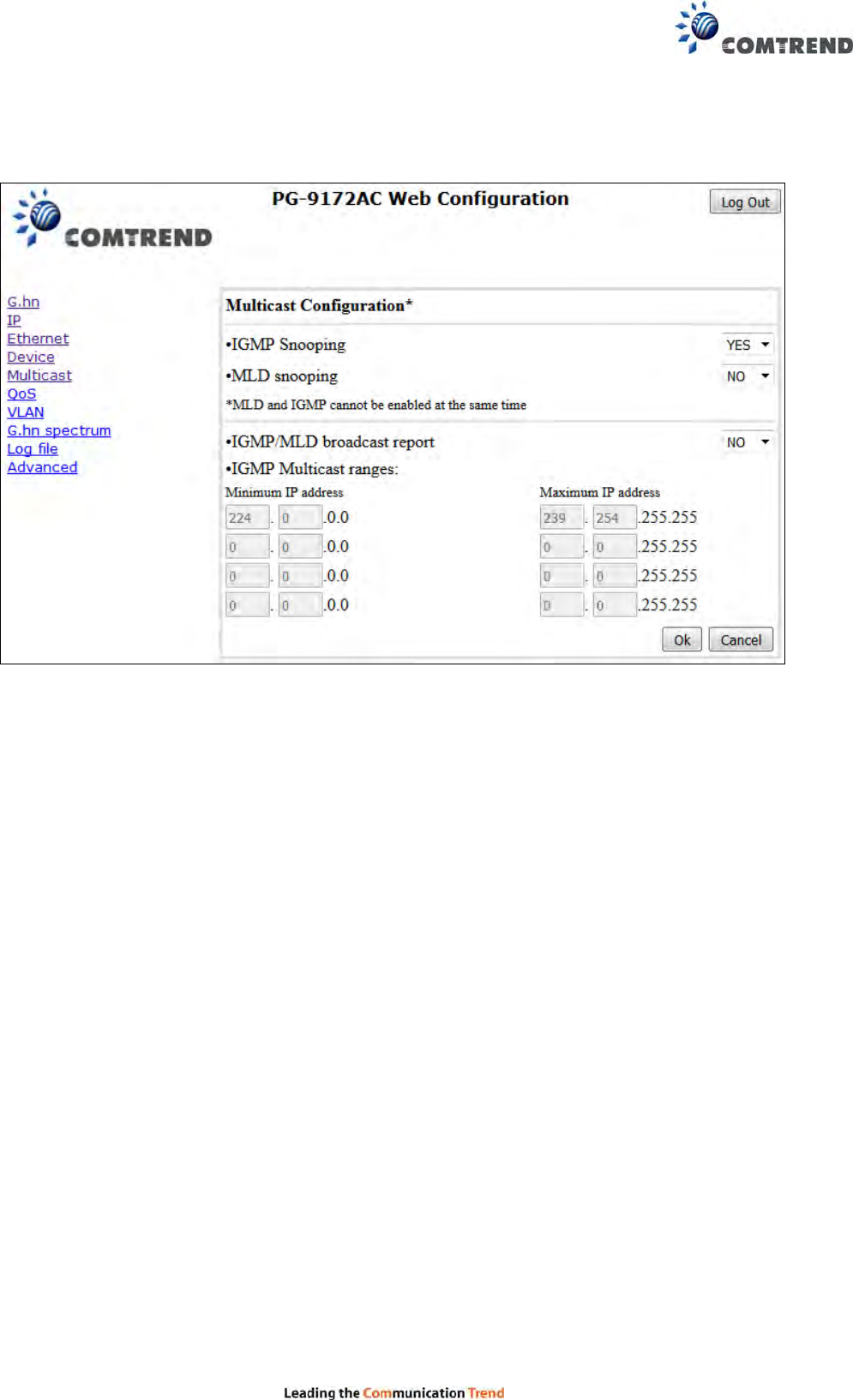
7.7.1 MCAST Configuration
In the MCAST Configuration tab of "My Network", IGMP snooping and MLD features can
be enabled or disabled. Also, IGMP multicast IP addresses ranges which the G.hn PLC
network will sniff; can be configured.
IGMP Snooping: Enable or Disable.
MLD Snooping: Enable or Disable.
IGMP/MLD broadcast report (allowed): set to NO for enabling reports dropping
until the video source is detected, this is a recommended setting when IGMP/MLD is
enabled. Set to YES for broadcasting reports until the video source is detected; this
implies the multicast video stream is sent as broadcast and it is the
recommended state when IGMP/MLD is disabled.
IGMP Multicast ranges configuration: 4 multicast IP address ranges can
be configured defining the minimum and maximum IP addresses of each range. Only
multicast traffic within these ranges will be processed.
45
7.8 QoS menu
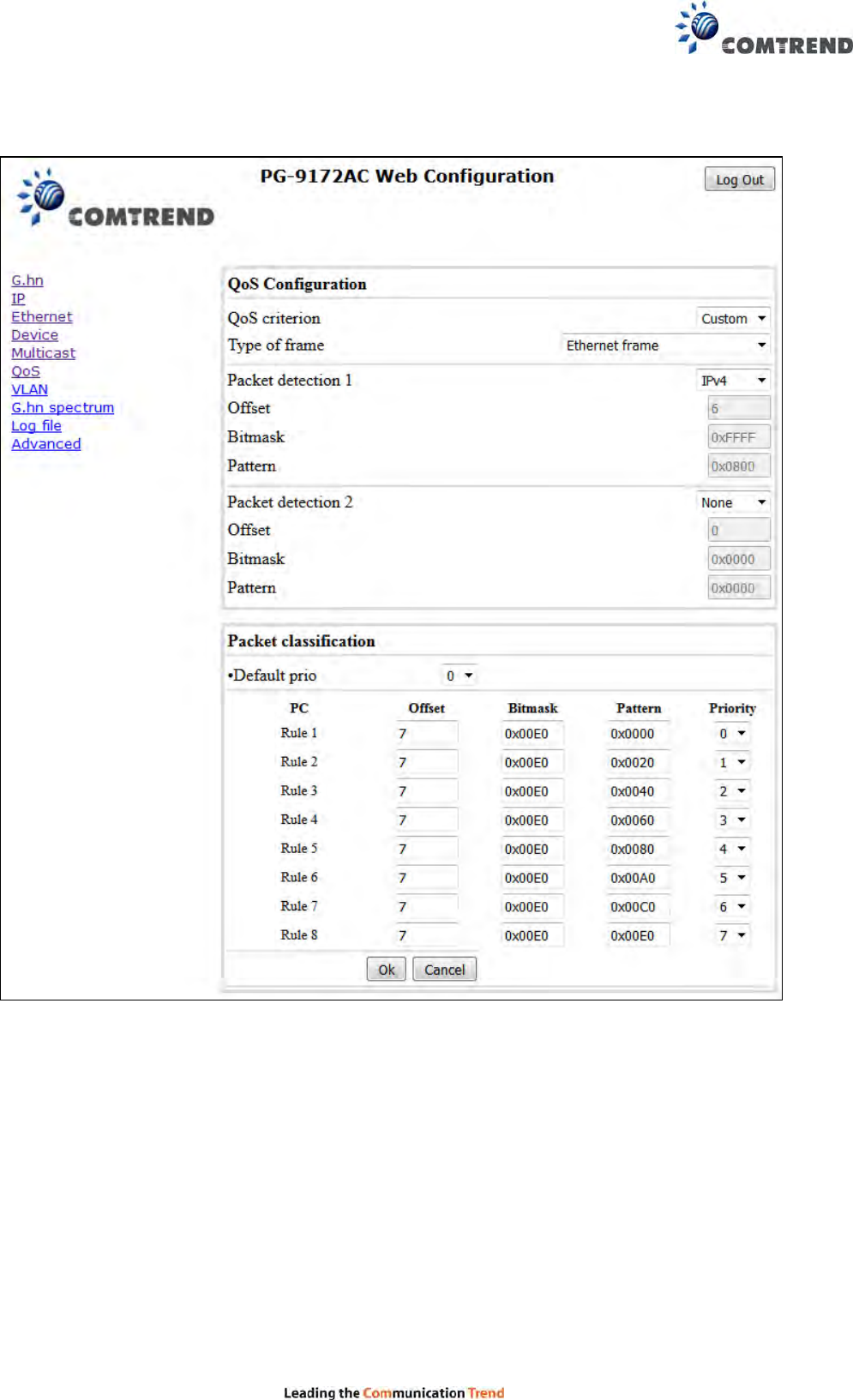
7.8.1 QoS Configuration
In the QoS configuration tab, the packet classifier can be managed to define a QoS rule for
incoming Ethernet traffic, and assign a priority to be used in the G.hn network. Press the
“Ok" button for loading the newly configured settings:
QoS CRITERION: a general criterion can be chosen among "None" (no QoS),
"Custom" and "802.1p".
Type of Frame: with this parameter the type of Ethernet traffic being transmitted by
the G.hn network should be selected. Based on this parameter, the internal offsets in
the system are adjusted. In the QoS tab, Ethernet frame offsets should be
set counting number as they appear in the sniffer SW (for instance, the same
field will be in a different position if normal Ethernet frames or 802.1Q tagged frames
exist).

46
Packet detection 1: first packet detection rule can be configured (offset, bitmask
and pattern). Packets which accomplish it will be sent to the classification module.
Packet detection 2: if second packet detection is also enabled, both, first
and second detection criteria must be accomplished to pass packets to
the classification module.
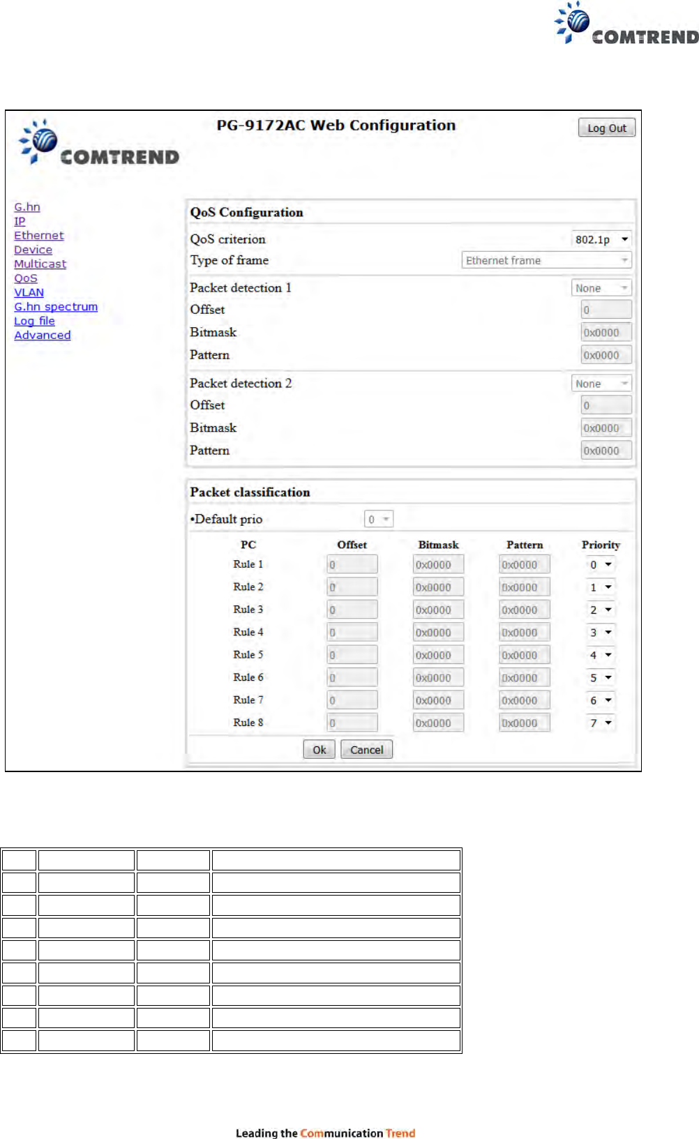
Packet classification: up to 8 classification rules can be defined in this section for
packets which have previously been correctly detected. For 802.1p only priorities can
be managed, offset, bitmask and pattern are predefined to sniff the PCP field.
Default priority: select default priority; which will be applied to
non classified incoming packets. Priority 7 is the highest. Priority 0 is the lowest.
47
Example
If QoS criterion: 802.1p, all other options are grayed out, and follow the QoS rules below.
According to G.9960 specs, the priority mapping recommended by [IEEE 802.1D] subclause
7.7.3 is presented in Table III.1. for four priority queues.
PCP Priority Acronym Traffic Types
1 0 (Third) BK Background
0 1 (lowest) BE Best Effort
2 2 (lowest) EE Excellent Effort
3 3 (Third) CA Critical Applications
4 4 (second) VI Video, < 100 ms latency and jitter
5 5 (second) VO Voice, < 10 ms latency and jitter
6 6 (highest) IC Internetwork Control
7 7 (highest) NC Network Control
In summary, the sequence of priority queue, (7,6) > (5,4) > (3,0) > (2,1)
48
7.9 VLAN Interface
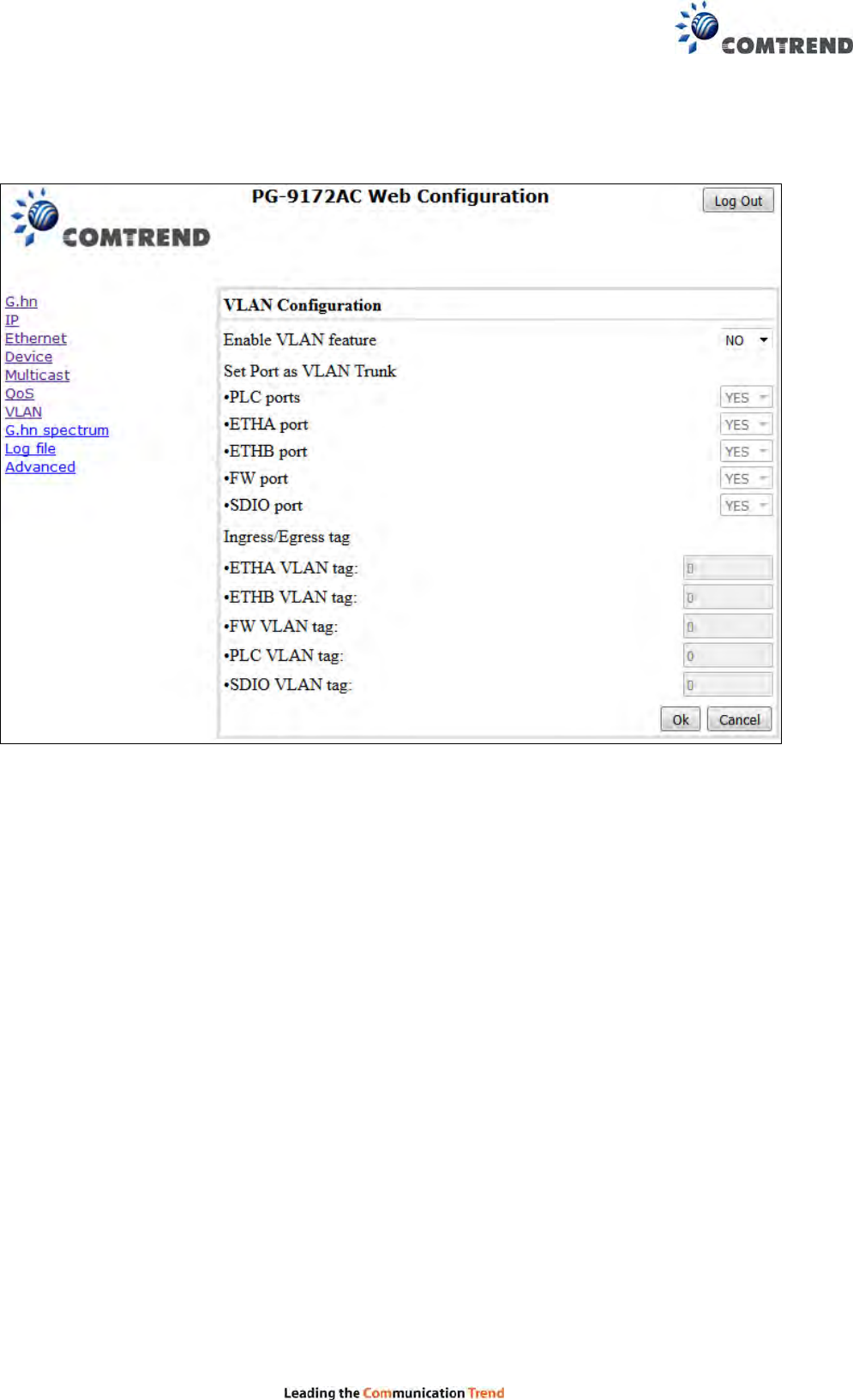
7.9.1 VLAN Configuration
In the VLAN Configuration tab of one G.hn node, a VLAN tag can be added or removed per
interface. Also, removing a tag at egress per interface can be also enabled or disabled:
Enable VLAN Configuration: Select No from the drop down menu to
disable completely the VLAN functionality, removing all tags.
Set Port as VLAN Trunk: Select Yes from the drop down menu for the ports that
you want to set as VLAN Trunk ports.
Ingress/Egress tag: A tag value (from 1 to 4095) per interface can be added in this
section. Set value to 0 for no tagging.
49
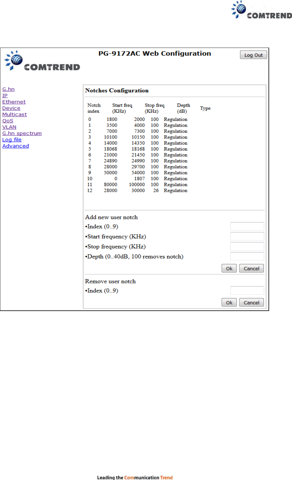
7.10 G.hn spectrum Interface
7.10.1 Notches
In this tab a table with all configured Notches of selected node will be shown. The table
is composed of next columns for every notch: Notch Number, Type of notch, Start Frequency
(KHz), Stop Frequency (KHz), Depth (in dB).
The first 13 notches (Regulation) are Read Only, RO, in the system and they can be neither
removed nor modified. The next 40 notches (Vendor) are defined by the vendor using SDK
and they are also RO. The last 10 notches (User) are R/W and they can be added/removed by
user using this tool.
To add new notches the user should fill the "Add a new User Notch" fields, setting Start
and Stop frequencies in KHz and depth in dB of notch and then press the "Ok" button. They
will be added in first User free position from number 0 to 9. (If successful, you can see a
record in the Type column)
To remove a User Notch, the "Remove a User Notch" section should be used, setting notch
number to be removed from 0 to 9 and pressing the "Ok" button.
50
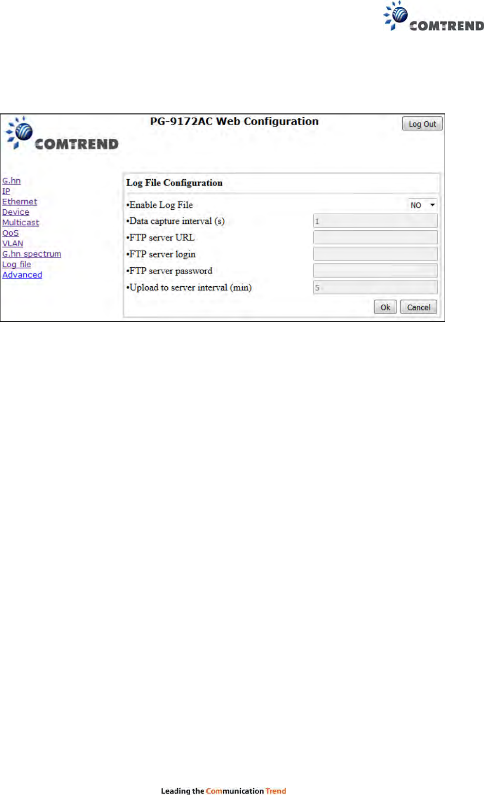
7.11 Log file Interface
7.11.1 Log File
In the Log File configuration the following settings can be read, and changed by clicking on
the corresponding "OK" button for the selected node:
Enable Log File set to YES for enabling Log File functionality in the node and set to
NO for disabling it.
Data Capture Interval sets the interval of time in seconds to capture data.
FTP Server URL configures the url for the remote FTP server where the files will be
uploaded.
FTP Server Login configures the user for the FTP server.
FTP Server Password configures the password for the FTP server.
Upload to Server Interval sets the interval of time in minutes to
send the captured file to the remote server.
51
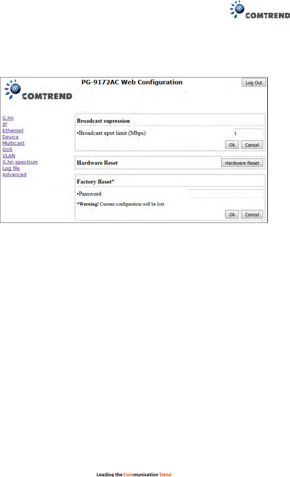
7.12 Advanced Interface
Broadcast suppression :In this tab the broadcast suppression feature can be managed.
Broadcast traffic higher than the selected value will be dropped.
Hardware Reset: Click on this button to perform a reboot in the node.
Factory Reset: Input the password: betera and click the OK button to perform a factory
reset. The current configuration will be lost.

52
Chapter 8 CLI commands for TR069 settings
via Telnet
A system reboot is required for new settings.
ACS URL settings,
nvram_set 2860 TR069URL [http://domain or IP/string]
For example:
nvram_set 2860 TR069URL http://220.128.128.235/cpe/?pd128
Display the current settings,
nvram_get 2860 TR069URL
ACS username,
nvram_set 2860 TR069Username [username]
For Example:
nvram_set 2860 TR069Username comtrend
Display the current settings,
nvram_get 2860 TR069Username
ACS password,
nvram_set 2860 TR069Password [password]
For example:
nvram_set 2860 TR069Password comtrend
Display the current settings,
nvram_get 2860 TR069Password
Periodic interval in seconds.
nvram_set 2860 TR069InformInterval [seconds]
For example:
nvram_set 2860 TR069InformInterval 3600
Display the current settings,
nvram_get 2860 TR069InformInterval

53
FCC Statement:
Federal Communication Commission Interference Statement
This equipment has been tested and found to comply with the limits for a Class B digital device, pursuant
to Part 15 of the FCC Rules. These limits are designed to provide reasonable protection against harmful
interference in a residential installation. This equipment generates, uses and can radiate radio frequency
energy and, if not installed and used in accordance with the instructions, may cause harmful interference
to radio communications. However, there is no guarantee that interference will not occur in a particular
installation. If this equipment does cause harmful interference to radio or television reception, which can
be determined by turning the equipment off and on, the user is encouraged to try to correct the
interference by one of the following measures:
● Reorient or relocate the receiving antenna.
● Increase the separation between the equipment and receiver.
● Connect the equipment into an outlet on a circuit different from that to which the receiver is connected.
● Consult the dealer or an experienced radio/TV technician for help.
FCC Caution: Any changes or modifications not expressly approved by the party responsible
for compliance could void the user’s authority to operate this equipment.
This device complies with Part 15 of the FCC Rules. Operation is subject to the following two conditions:
(1) This device may not cause harmful interference, and (2) this device must accept any interference
received, including interference that may cause undesired operation.
This device is restricted for indoor use.
For product available in the USA/Canada market, only channel 1~11 can be operated. Selection of
other channels is not possible.
IMPORTANT NOTE:
FCC Radiation Exposure Statement:
This equipment complies with FCC radiation exposure limits set forth for an uncontrolled environment.
This equipment should be installed and operated with minimum distance 20cm between the radiator &
your body.
54
IC Statement:
This device complies with Industry Canada license-exempt RSS standard(s). Operation is subject to the
following two conditions: (1) this device may not cause interference, and (2) this device must accept any
interference, including interference that may cause undesired operation of the device.
Le présent appareil est conforme aux CNR d'Industrie Canada applicables aux appareils radio exempts
de licence. L'exploitation est autorisée aux deux conditions suivantes : (1) l'appareil ne doit pas produire
de brouillage, et (2) l'utilisateur de l'appareil doit accepter tout brouillage radioélectrique subi, même si
le brouillage est susceptible d'en compromettre le fonctionnement.
For product available in the USA/Canada market, only channel 1~11 can be operated. Selection of
other channels is not possible.
Pour les produits disponibles aux États-Unis / Canada du marché, seul le canal 1 à 11 peuvent être
exploités. Sélection d'autres canaux n'est pas possible.
This radio transmitter (4013A-PG9172AC) has been approved by Industry Canada to operate with the
antenna types listed below with the maximum permissible gain indicated. Antenna types not included in
this list, having a gain greater than the maximum gain indicated for that type, are strictly prohibited for use
with this device.
Le présent émetteur radio (4013A-PG9172AC) a été approuvé par Industrie Canada pour fonctionner
avec les types d'antenne énumérés ci-dessous et ayant un gain admissible maximal d'antenne. Les types
d'antenne non inclus dans cette liste, ou dont le gain est supérieur au gain maximal indiqué, sont
strictement interdits pour l'exploitation de l'émetteur.
Ant. Brand Holder Model Name Antenna Type Connector Gain (dBi)
2.4GHz 5GHz
1 Master Wave Technology
Co., Ltd. 502219-293 Dipole Antenna I-PEX 2.41 3.80
2 Master Wave Technology
Co., Ltd. 502219-292 Dipole Antenna I-PEX 2.31 3.62
The device for operation in the band 5150–5250 MHz is only for indoor use to reduce the potential for
harmful interference to co-channel mobile satellite systems.
les dispositifs fonctionnant dans la bande 5150-5250 MHz sont réservés uniquement pour une
utilisation à l’intérieur afin de réduire les risques de brouillage préjudiciable aux systèmes de satellites
mobiles utilisant les mêmes canaux.
The maximum antenna gain permitted for devices in the band 5725-5850 MHz shall be such that the
equipment still complies with the e.i.r.p. limits specified for point-to-point and non-point-to-point operation
as appropriate.
le gain maximal d’antenne permis (pour les dispositifs utilisant la bande 5725-5850 MHz)
doit se conformer à la limite de p.i.r.e. spécifiée pour l’exploitation point à point et non point à point,
selon le cas.
IMPORTANT NOTE:
IC Radiation Exposure Statement:
This equipment complies with IC RSS-102 radiation exposure limits set forth for an
uncontrolled environment. This equipment should be installed and operated with minimum distance 20cm
between the radiator & your body.
Cet équipement est conforme aux limites d'exposition aux rayonnements IC établies pour un
environnement non contrôlé. Cet équipement doit être installé et utilisé avec un minimum de 20 cm de
distance entre la source de rayonnement et votre corps.