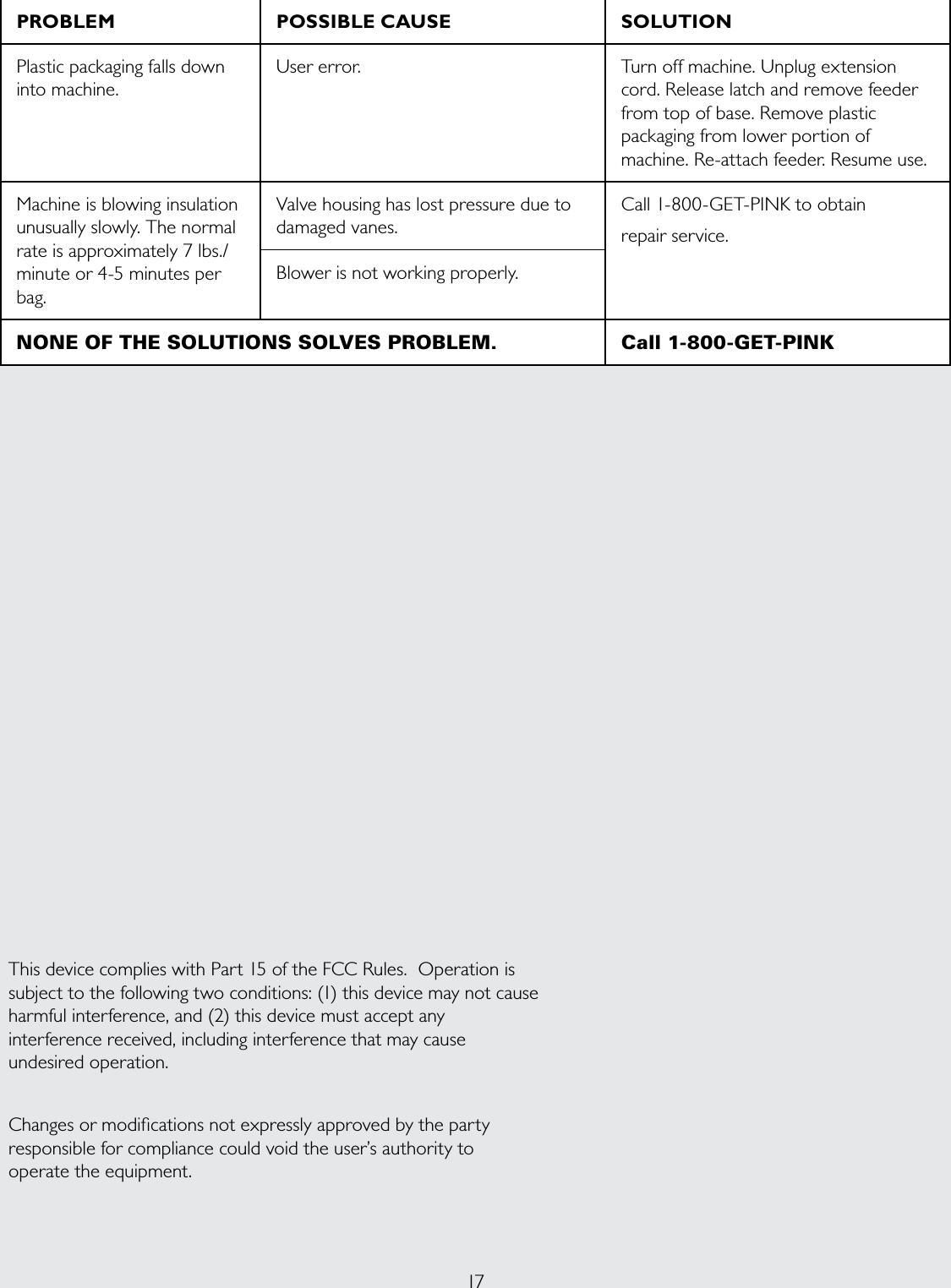
Concept Engineering 40019 Atticat Remote Transmitter User Manual
Concept Engineering, Inc. Atticat Remote Transmitter
UserManual.wiki
>
Concept Engineering
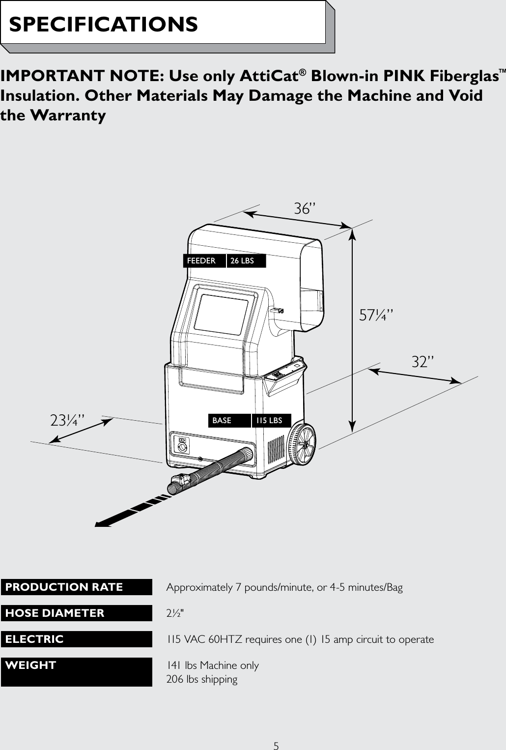
>
40019 User Manual
User Manual
Navigation menu
Upload a User Manual
Namespaces
Wiki Guide
HTML
PDF
Info
Views
User Manual
Discussion / Help
Navigation