Concept Engineering 40019 Atticat Remote Transmitter User Manual
Concept Engineering, Inc. Atticat Remote Transmitter
User Manual
1
OWNERS MANUAL
®

2
Introduction and AttiCat® System Overview ........................................3
System Safety Features ...........................................................4
Specications ...................................................................5
Choosing an Extension Cord and Using a Generator .................................6
Glossary .......................................................................7
Installation Instructions
Required Installation Materials ..............................................8
Personal Protective Equipment .............................................8
Job Preparation ..........................................................8
How to Install ............................................................9
Maintenance Inspections
Visual Inspection-External .................................................10
Visual Inspection-Internal ..................................................12
Operational Inspection ....................................................13
Troubleshooting Guide ...........................................................15
TABLE OF CONTENTS
3
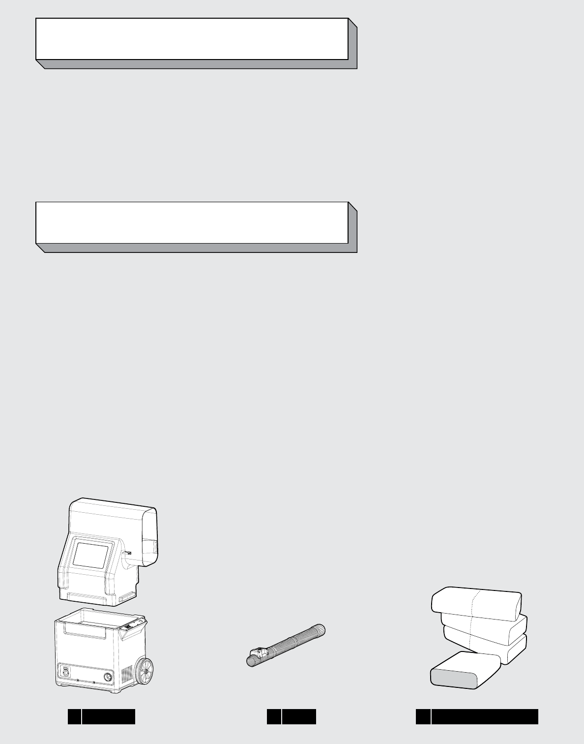
1 MACHINE 3 BAGS OF INSULATION2 HOSE
INTRODUCTION
SYSTEM OVERVIEW
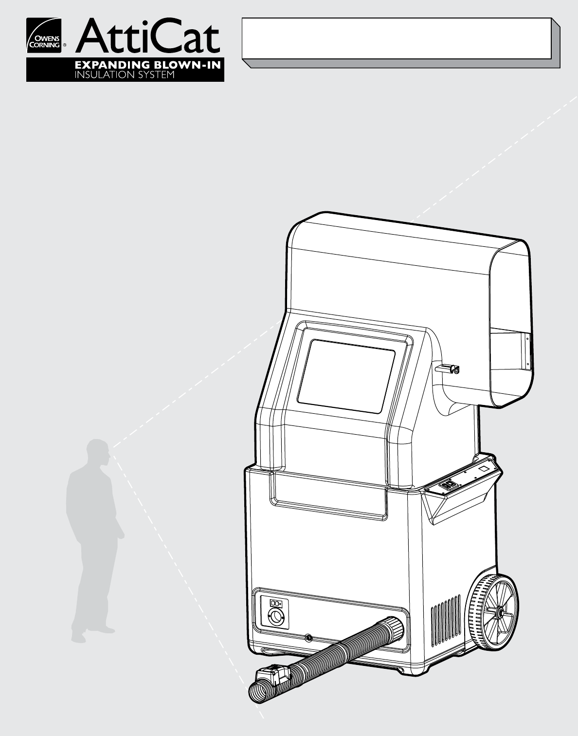
This manual is provided with the AttiCat® Expanding
Blown-in Insulation System developed by Owens Corning.
This document is to be used to understand the system
and to assist in the diagnosis and resolution of minor
machine problems.
The AttiCat® Expanding Blown-in Insulation System
consists of:
1) a blowing machine,
2) the hose, and
3) the bags of expanding loosefill insulation.
The AttiCat® blowing machine consists of the feeder and
the base. The feeder is the portion of the system where
the operator inserts the insulation; a gravity feed guides the
insulation down onto the agitator bars in the base. Paddles
on the rotating agitators break apart the insulation into
smaller pieces. Insulation ows through the agitators and
into the revolving valve, and is then blown into the hose by
the blower. The entire path - from agitators through the
hose - is required to properly condition the insulation for
use in the attic.
The hose is made up of two or three sections. Clamps are
used to attach the sections together. The hose is attached
to the base of the machine by a twist-on coupling. The attic
end of the hose has a wireless remote control unit to start
and stop the ow of insulation.
The system is completed by the bags of the loosell
blown-in insulation product. Each of the parts is integral
to the proper operation and quality of the blown-in
insulation process.

4
FEEDER The feeder is designed to enclose the
insulation hopper to protect against injury
by prohibiting easy access to the agitator
bars within the base unit while the
machine is running.
The machine will not run if the feeder is
not attached. This further protects the
operator from the moving agitator bars
and possible injury.
AUTOCUTTER The AUTOCUTTER assembly completely
encloses a standard utility knife blade. A
blade guard on the inside of the feeder
protects users from any cutting injuries.
CENTER OF GRAVITY Most of the machine’s mass is
concentrated in the lower unit, creating a
very stable machine despite its height.
(CAUTION: The base unit should be
lifted by two people.) The center of
gravity also enables the machine to be
easily tipped slightly and wheeled around
like a dolly by one person.
SYSTEM SAFETY FEATURES
5
PRODUCTION RATE Approximately 7 pounds/minute, or 4-5 minutes/Bag
HOSE DIAMETER 2½"
ELECTRIC 115 VAC 60HTZ requires one (1) 15 amp circuit to operate
WEIGHT 141 lbs Machine only
206 lbs shipping
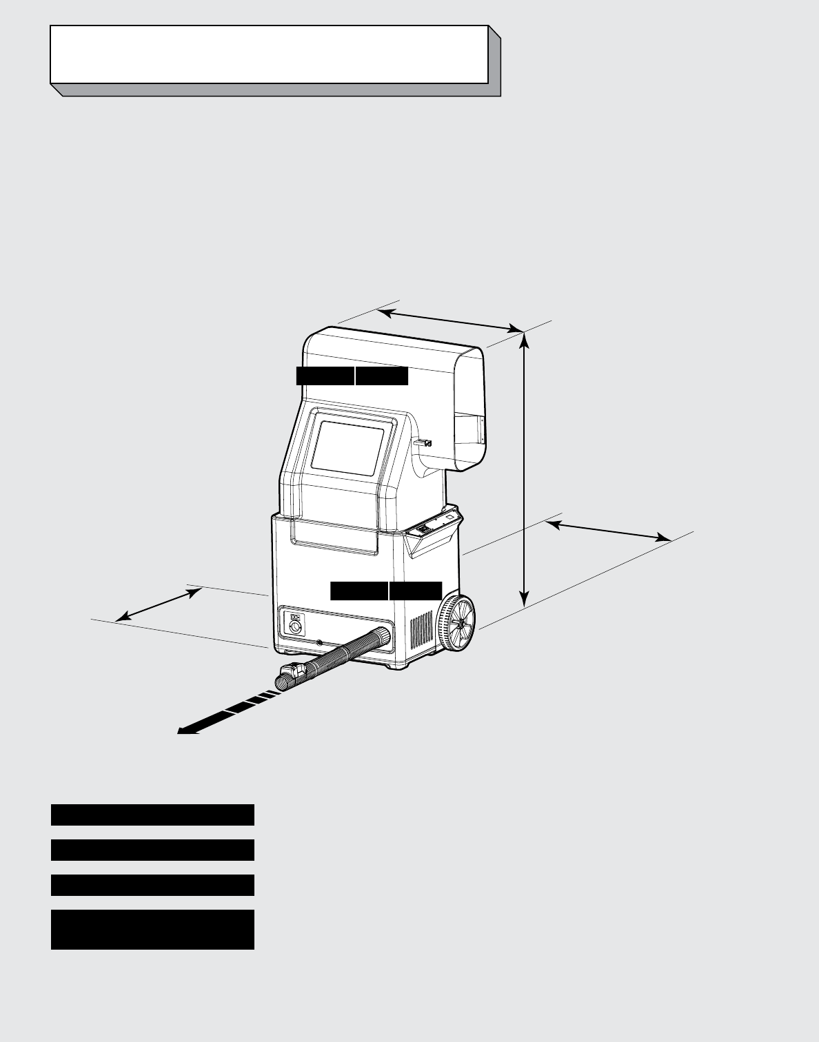
SPECIFICATIONS
IMPORTANT NOTE: Use only AttiCat® Blown-in PINK Fiberglas™
Insulation. Other Materials May Damage the Machine and Void
the Warranty
36”
57¼”
32”
23¼”
FEEDER 26 LBS
BASE 115 LBS

6
GENERATORS AND EXTENSION CORDS
Your AttiCat® machine will operate on power from a
commercial-sized generator. No household generators may
be used due to the high inrush requirements of the
AttiCat® machine. Also, generators made by Honda,
Yamaha, Coleman and Generac are not
recommended. While they are of high quality, these
generators do not have the inrush protection devices
necessary to start the AttiCat® machine and protect the
generator. The start-up requirement for the AttiCat®
machine is 2000 watts; normal operating requirement is
1600 watts. We recommend a generator of not less
than 3000 watts, 115 VAC. In addition, the AttiCat®
Manufacturer recommends generators with a 50% power
boost feature that aids the generator in high current
startups.
Running additional equipment from the same generator
means you will need to know the total electrical
requirements before selecting the correct size of generator.
For details on selecting and purchasing a generator, please
call 1-800-GET PINK™.
An input line reactor will protect the AttiCat® electronics
from transient overvoltage conditions and harmful
harmonic distortions (over 10%) which are common
problems with electronic generators. If you plan to power
the AttiCat® machine from a generator other than as
specied by the AttiCat® manufacturer, contact the
AttiCat® manufacturer to purchase the input line reactor.
This particular line reactor is made specically for machines
utilizing a Variable Frequency Drive such as used by the
AttiCat® machine. It is enclosed in a weather-proof box
designed for proper heat dissipation. The box can be either
mounted on the AttiCat® machine or at the generator.
Choosing the Correct Extension cord
Use only a three conductor, grounded, 14 gauge, 15 amp
extension cord, 100 feet maximum.
Note:
1. Adding Additional Power Cords will damage the
machine and void your Warranty.
2. Using a generator of insufficient size or incorrect type
will void your Warranty.
7
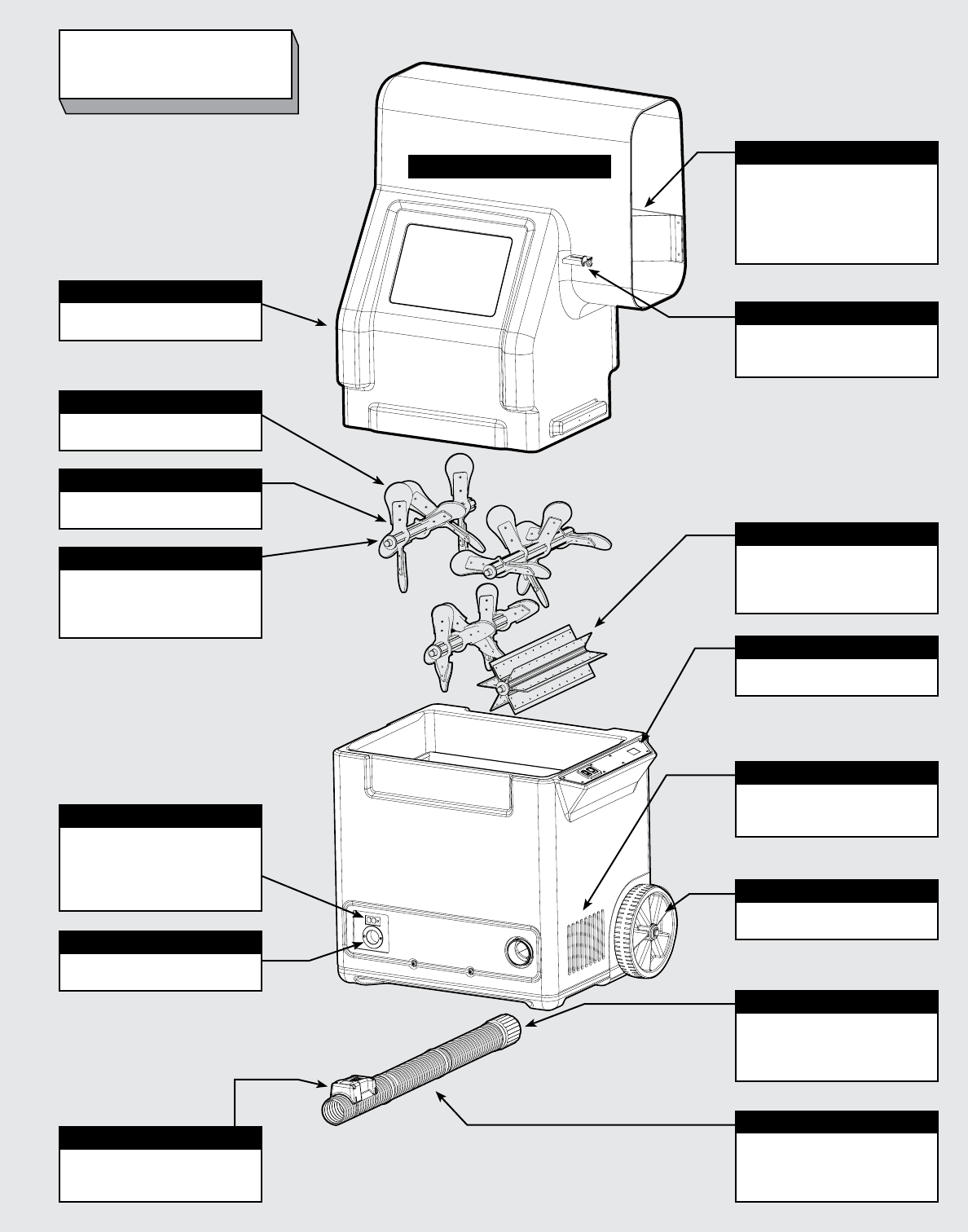
GLOSSARY
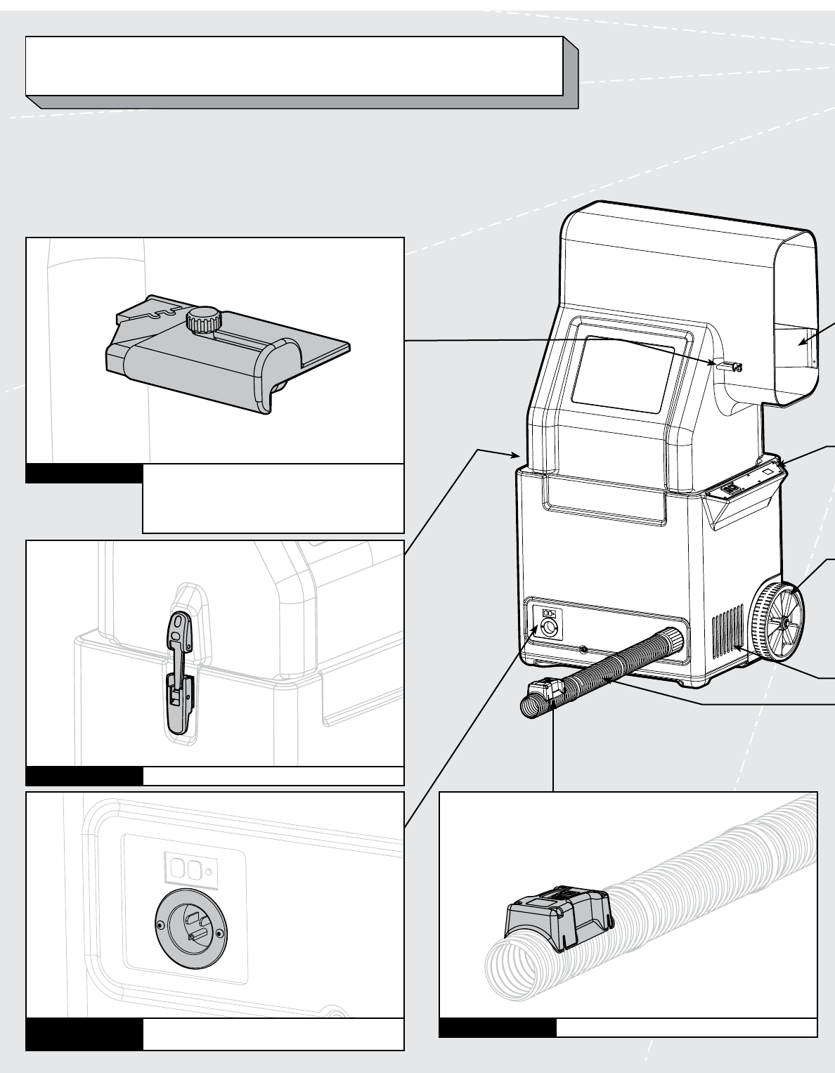
FEEDER
BAIL GUIDE
Folded plastic part inside feeder
opening used to guide half-
bags of insulation toward the
AUTOCUTTER so the package
can be cut, opened and released
easily into the feeder.
AUTOCUTTER
Small utility blade attachment used
to cut each half-bag of insulation
when fed into machine.
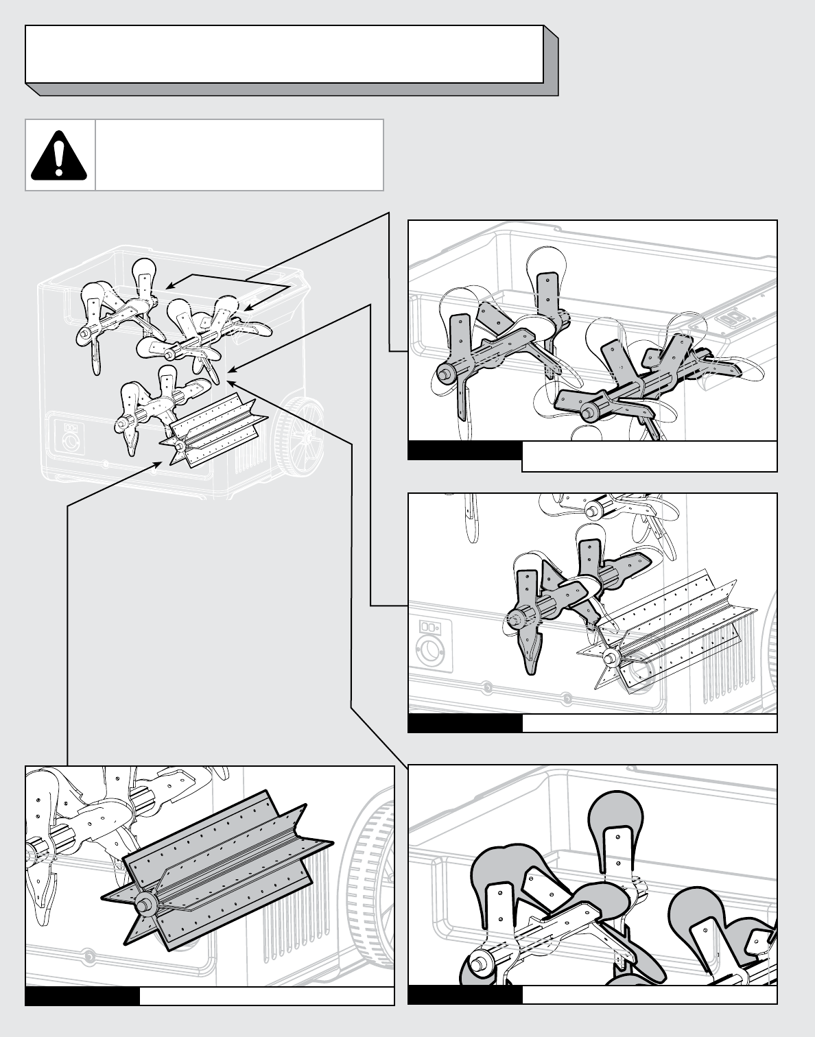
VALVE
Revolving vanes attached to the
blower (blown-in insulation is
grabbed by the six (6) vanes and
blown into the hose.)
CONTROL PANEL
Allows operator to start and stop
the machine.
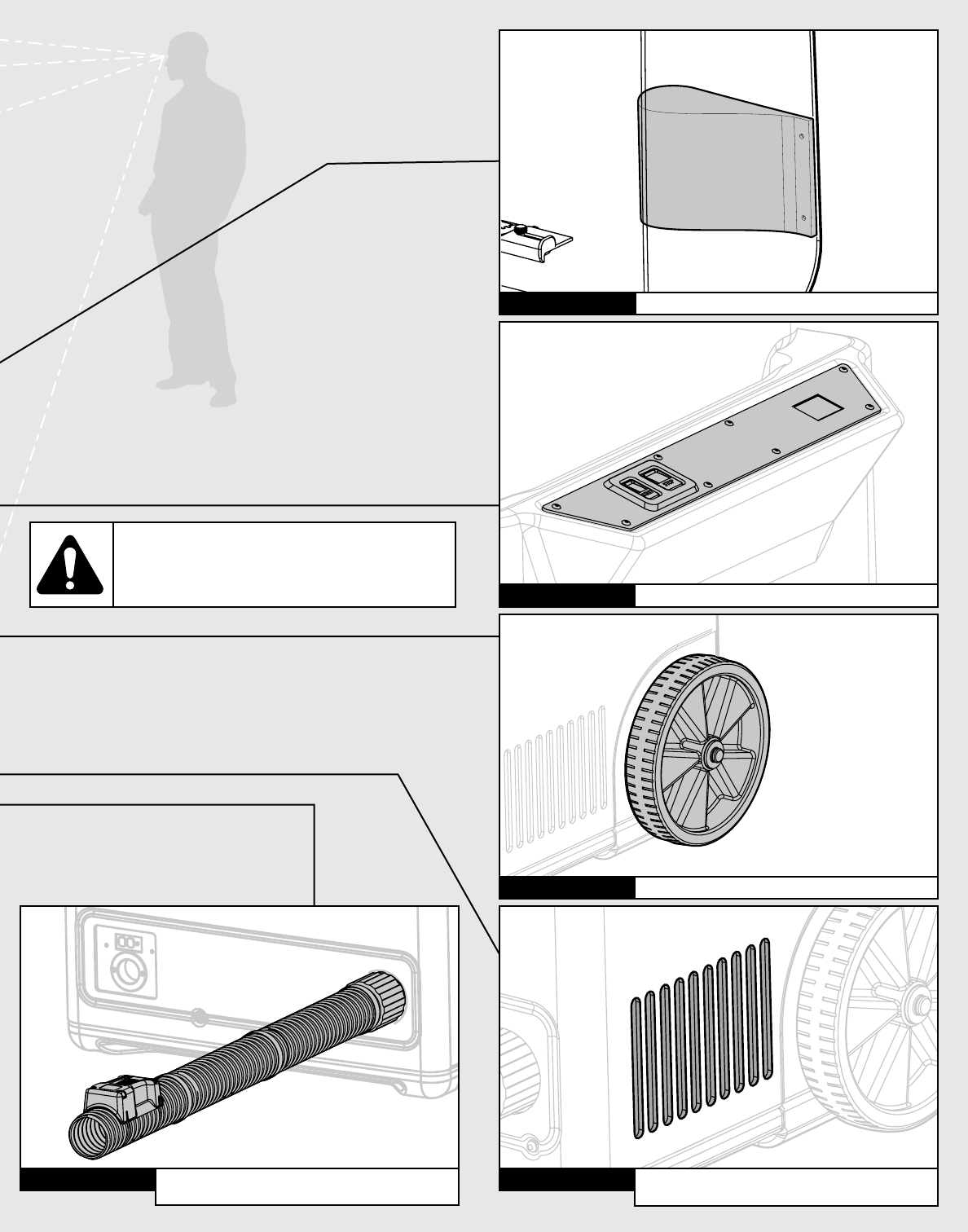
AIR INTAKE VENTS
Take air into the base unit; covered
with screens to keep debris from
being pulled into the machine.
WHEELS
Allow machine to be tipped back
and moved around like a dolly.
HOSE COUPLING
Machine end of hose has twist-on
hose attachment allowing entire
hose to be securely attached to
base unit.
HOSE
Hose sections are attached to each
other with hose clamps; entire
hose is attached to machine with
twist-on hose coupling.
ATTIC WIRELESS REMOTE
Attic end of hose has ATTIC
REMOTE controlling machine
from attic.
GFCI
Ground Fault Circuit Interrupter;
Shuts down the current ow
when a ground fault is detected
to protect the user from electrical
shock.
ELECTRICAL INLET
14-gauge, 15-amp extension cord
attaches here.
LATCH
Attaches the feeder to the base
unit. (On rear of feeder.)
AGITATOR SHAFTS
Attached to the agitator shafts
(revolve within the base unit to
break apart the blown-in insulation
material.)
AGITATOR BARS
Aluminum arms that hold the
riveted rubber agitator paddles.
AGITATOR PADDLES
Rubber ends riveted to the agitator
bars.

8
Job Preparation
• Examineyourattictobesureitisadequatelyventilated.
Owens Corning recommends a minimum of 1 square
foot of venting for every 150 square feet of space to
be insulated.
• Installarigidbarrieraroundtheatticaccessopening
to prevent insulation from falling out when you open
the attic door (Owens Corning FanFold Foam Residing
Board; Foamular®, Insulpink®, or ProPink® Foam
Insulation Board; or equivalent). Be sure the barrier
is taller than the thickness of the insulation you plan
to install.
• Inspectanyductworkintheatticandmakesureall
connections are sound. If necessary, seal duct joints
prior to installing insulation.
• PlacetheAttiCat® machine outside of your house or in
your garage.
• Laydropclothsinthehousealongthepathofthehose
to protect floors and other surfaces.
• Runthehoseintotheattic.Extendenoughhoseto
reach the furthest point in the attic. NOTE: AttiCat®
machine shoots insulation a distance of approximately
8 to 10 feet.
• TheAttiCat® system works with two people–one in
the attic installing and the other operating the machine.
Personal Protective Equipment
• Protectiveclothingandequipment,includingaproperly
fitted NIOSH or MSHA approved disposable dust
respirator (such as 3M Model 8210, Model 8271 for
high-humidity environments, or equivalent), gloves,
goggles, and a long-sleeve shirt and pants.
Required Installation Materials
• BagsofAttiCat® Blown-in PINK Fiberglas™ Insulation
(calculate number of bags needed using the chart on
the bag)
• AttiCat® machine and hose assembly
• Extensioncord(three-conductor,withground,
14-gauge, 15-amp)
• Dropcloths
• Eaveorsoffitventilationbafflingmaterial,suchas
Owens Corning’s raft-R-mate® attic vents
• Cardboardormetalbaffling
• Knifetocutinsulationbags
• AttiCat® rulers and a marking pen
• Staplegun
• Lightingandaladdertosafelyaccessattic
Owens Corning shall not be responsible for any injury, damage, loss, cost, expense, or liability relating to failure to follow these instructions. Failure to follow these insulation instructions
may affect Owens Corning’s obligations under this product’s limited warranty.
OPERATING INSTRUCTIONS
CAUTIONS
• Donotblockeaveventing(soffitvents)with
insulation. Use vent baffles such as Owens Corning
raft-R-mate® attic vents (or equivalent) between eave
vents and attic to ensure air flow.
• Whenworkingintheattic,walkonlyontheceiling
rafters or joists and not on the ceiling. Be careful of
overhead obstructions and nails penetrating through
the roof deck.
• Maintainaminimumclearanceof3”aroundany
heat-generating sources (lights, flues, etc.) in the attic.
If a light fixture is labeled IC-rated, it is safe to lay
insulation over it.
WARNINGS
• KEEPHANDSANDTOOLSAWAYFROMANY
MOVING PARTS.
• DONOTATTEMPTTOCLEANTHEAttiCat®
MACHINEORHOSEUNTILMACHINEIS
COMPLETELYOFFANDEXTENSIONCORDIS
DISCONNECTED.
• NEVEROPERATETHEAttiCat® MACHINE IF IT
OR THE OPERATOR IS STANDING IN WATER.
SERIOUSINJURYMAYRESULT.
9
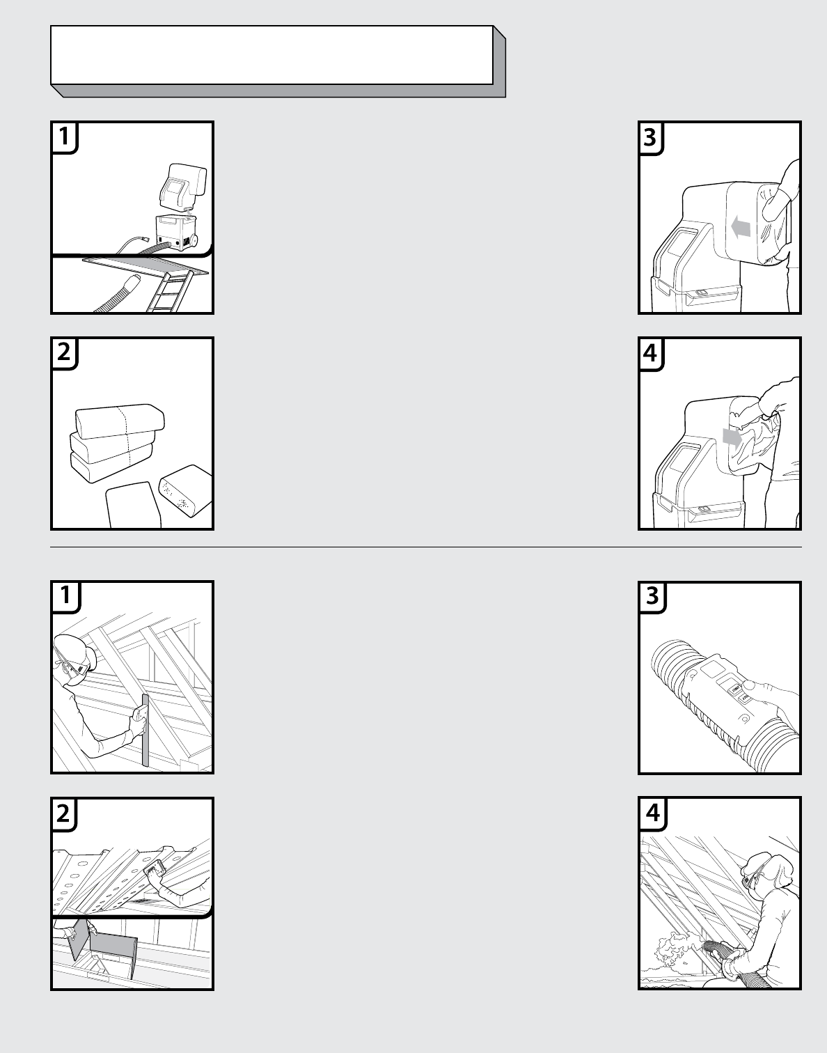
• Plugextensioncordinto
AttiCat® machine; connect
to a standard 115 V
electrical outlet. Green
light on control panel will
illuminate.
• Connecthosetomachine
and take the other end into
the attic.
• Feedonlyhalfbagstoavoid
jamming and damaging the
machine. Using a knife, cut
bag of insulation along cut
line. Break package in half;
machine’s feeder is
specifically designed to
accommodate a half-bag of
AttiCat® PINK Fiberglas™
Blown-in Insulation.
• Holdthehalf-bagbyend
flaps and insert cut end
into machine. Push half-bag
completely into feeder until
it stops. The built-in
Autocutter will cut plastic
packaging thereby releasing
insulation into the machine.
• Removepackagingfrom
machine. IMPORTANT!
PACKAGINGMAYCLOG
MACHINE AND
SHOULDBEREMOVED
IMMEDIATELYONCE
FIBERGLASSISRELEASED
INTO FEEDER.
• DoNOTattemptto
forcefully push or hand-
feed loose insulation down
into machine.
• Addanotherhalf-bagof
insulation once the machine
feeder has emptied and the
agitator paddles can be
seen through window.
• Usingastaplegun,install
AttiCat® rulers on joists,
roof trusses, or vertical
framing to determine how
much insulation you need
to add. Install one per
every 300 ft2/28 m2 so that
they are clearly visible.
• Installcardboardormetal
baffling around heat-
generating sources such as
can lights or flues/metal
chimneys; keep cardboard
and insulation at least 3”
from heat sources.
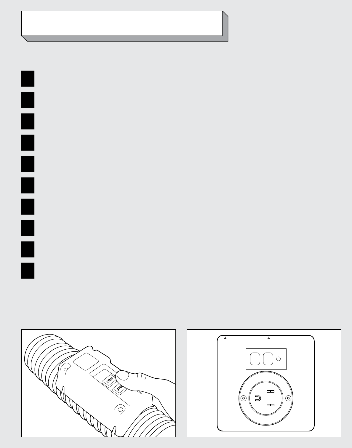
• PresstheSTARTbuttonon
the remote to begin flow of
insulation. There will be a
slight delay from the time
the blower starts and the
time the agitators begin
rotating. To stop the flow of
insulation at any time, press
the STOP button on the
remote; this will stop the
AttiCat® machine.
• Directthehosetowardthe
eaves, and begin by blowing
insulation at the point
furthest from the attic
opening. Insulation should
flow out of the hose and
fall onto the surface 8 to 10
feet away.
• Aseachatticsectionis
filled, move slowly
backward toward the attic
opening. Repeat this
process until attic is fully
insulated.
• Ensureeavesventsand
heat-generating fixtures are
not covered with insulation.
• Whenyou’reclosetothe
attic opening, use gloved
hands to deflect the
insulation downward.
Assemble machine.
Run hose to attic.
Cut bags in half.
Push half bag into
machine.
Remove packaging.
HOW TO INSTALL
Install eaves bafes
and rigid barrier.
Install rulers. Push remote
“START” button to
start the machine.
Blow insulation to
desired depth.
At the machine (person #1)
In the Attic (person #2)
10
VISUAL INSPECTION EXTERNAL
First, visually inspect all sides of the machine to check for
cracks or other damage to the outside of the feeder and
lower unit.
Then, thoroughly inspect the following assemblies, making
sure they are still attached and in working order.
ATTIC REMOTE Is the remote missing or damaged?ELECTRICAL
CONNECTION
Is inlet panel damaged? Check for bent prongs or
missing screws.
LATCH One on side of machine.
1
2
AUTOCUTTER Is the blade (1) present?
Does the blade appear dull or damaged?
Is the complete cutter assembly - including thumb
screw (2) - intact?
Is there insulation material blocking the blade?
11
INTAKE VENTS Use a shop vac to remove accumulated insulation/
debris from vents (on both ends of machine
BAIL GUIDE Helps guide insulation into the machine.
WHEELS Machine should have two wheels per base.
HOSE ASSEMBLY Is there a remote? Check hose for cracks, cuts or other
damage, and presence of all couplers and clamps.
CONTROL PANEL Verify all buttons are present and not damaged.
NOTE:
Before beginning external inspection, be
sure to turn off and unplug machine.
12
VISUAL INSPECTION INTERNAL
NOTE:
Before beginning internal inspection, be sure
to turn off and unplug machine.
VALVE (6 SEALS) Check for bent, broken or cracked valve seals.
UPPER AGITATORS Verify that both upper agitators are not cracked
or missing.
LOWER AGITATOR Verify that the lower agitator is not cracked or missing.
PADDLES Check for missing, loose, or damaged paddles.
13
OPERATIONAL INSPECTION
GFCI
USE 14 GAUGE
15 AMP RATED
EXTENSION
CORD
115 VOLT, 12 AMP
60 Hz
Warning:
RISK OF ELECTRIC SHOCK. DO NOT EXPOSE
TO RAIN. STORE INDOORS. CONNECT TO A
PROPERLY GROUNDED OUTLET ONLY.
AVERTISSEMENT:
RISQUE DE SECOUSSES ÉLECTRIQUES.
NE PAS EXPOSER À LA PLUIE. RANGER À
L’INTÉRIEUR. BRANCHER UNIQUEMENT SUR
UNE PRISE DE COURANT ADÉQUATEMENT
MISE À LA TERRE.
Follow this short inspection to verify that the machine is in working order. Ensure no insulation is in
the machine.
1Connect complete hose assembly to hose port on base of machine.
2Connect grounded (14 gauge, 15 amp) extension cord to three-pronged connector on lower unit of machine and
then connect cord to a 115 volt electrical source.
3Press Reset Button on the GFCI (may already be depressed).
4Press the Start Button.
5Observe agitators through inspection window to ensure they are turning.
6Check for air owing out the end of the hose.
7Press the stop button to turn the machine off.
8Press start button on the attic remote. Repeat steps 5 & 6.
9Press Stop button on the attic remote.
10 Disconnect extension cord.
14
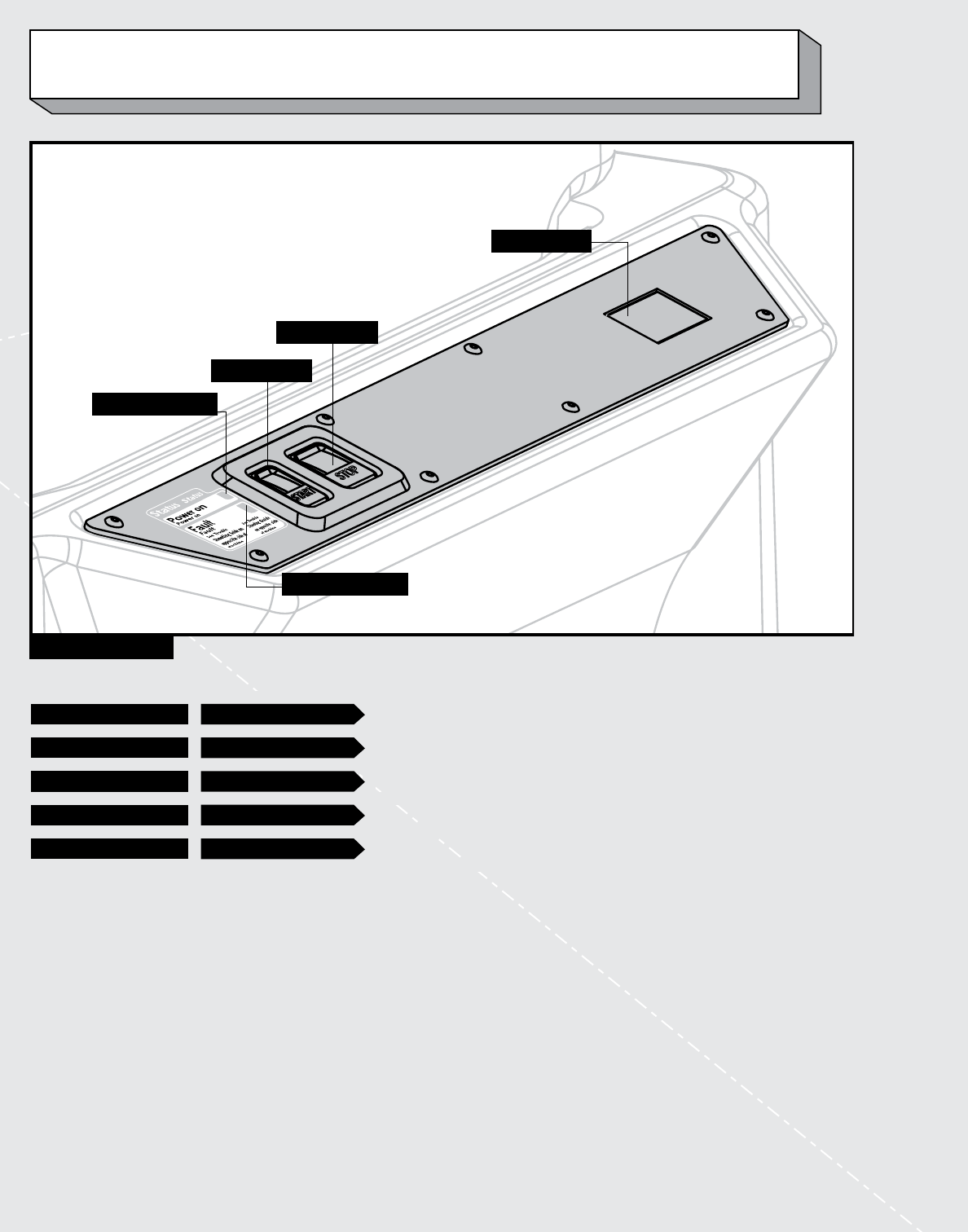
CONTROL PANEL
FAULT INDICATOR
START BUTTON
POWER INDICATOR
STOP BUTTON
HOUR METER
OPERATIONAL INSPECTION CONTINUED
POWER INDICATOR WHEN LIT (GREEN) Electrical power is present, and the machine is ready to use.
FAULT INDICATOR WHEN FLASHING (RED) Indicates an agitator motor overload (jam).
START (GREEN) WHEN PRESSED Starts blower, then after 3 second delay, agitator starts.
STOP (RED) WHEN PRESSED Stops both the agitator and blower operation.
HOUR METER DURING OPERATION Records the number of hours used.

15
PROBLEM POSSIBLE CAUSE SOLUTION
Machine will NOT start and
greenPowerLightisNOT
on at Control Panel
Extension cord not plugged in to
machine or wall outlet.
Plug extension cord into machine and
into standard 115V electrical outlet.
GFCI (Ground Fault Circuit Interrupter)
has been tripped.
Reset the GFCI:
• Unplugthemachine,wait2minutes
and plug it back in.
• Pressreset.
• Ifitcontinues,tryanothercircuitand
a new extension cord.
Circuit Breaker is turned off or tripped. Check household circuit breakers
or fuses.
Feeder is not attached to base or not
attached to base properly.
Make sure feeder is attached to base
and latches are secured. Feeder must be
placed with the feeder opening directly
above the control panel.
FaultlightisFLASHINGat
Control Panel
A material jam has stopped the machine
from running.
Unplug machine. Remove feeder and
clear material jam, then replace feeder.
Plug machine in.
ATTIC REMOTE does not
work, but machine turns on
at control panel.
Battery is not working. Unscrew the 4 screws on top of the
Attic Remote. Remove the remote and
the 2 mounting rings from the hose.
Turn remove over and remove the
screw holding the battery retainer.
Replace the 2 AAA batteries.
Reattach the battery retainer and place
the remote and mounting rings back on
the hose.
Secure the 4 screws to the mounting
rings.
None of the above solutions works Control the machine from the
control panel.
Machine Runs Slowly LowVoltageCircuit Plug into another electrical outlet on a
different circuit
Incorrect Power Cord Use specied extension cord
TROUBLESHOOTING GUIDE

16
PROBLEM POSSIBLE CAUSE SOLUTION
Insulation not released from
plastic packaging when
inserted into machine feeder.
The package of insulation was not cut
in half.
Cut the package of insulation in half
along dotted line on package.
Too much insulation is being inserted
into the machine at once.
Insert only one half-bag into machine
feeder at a time.
The insulation is being inserted
incorrectly into the machine.
Insert the half-bag open (cut) end rst;
push half-bag fully to the far end of the
feeder wall.
There is no blade in the AUTOCUTTER
or the blade is dull or broken.
Turn off machine. Unplug extension
cord. Insert standard utility knife blade
into AUTOCUTTER assembly.
Blade could be clogged with insulation. Unclog blade.
Insulation released from
plastic packaging, but
machine appears to be
jammed.
Too much material is in the feeder. Check to see if any insulation is coming
out of open end of hose.
Check to see if insulation is owing
through machine by observing operation
through inspection window.
Turn off machine. Unplug extension
cord. Release latches and remove feeder
from top of base. Remove insulation
from base of machine.
Plug machine in, turn on, and press
start button.
Insulation was pushed down into the
machine.
Insulation and air not coming
out of hose.
The hose is not attached. Attach the hose to the machine.
There is a blockage in the hose. Remove hose and shake vigorously to
dislodge insulation and resume ow.
Air, but no insulation coming
out of hose.
Machine is jammed. See previous section.
Either the agitators or valve are
not turning.
Secure repair assistance.
After inserting insulation into
machine feeder, plastic
packaging is difcult to
remove.
Half-bag is not inserted all the way into
the feeder and past the
AUTOCUTTER.
Push half-bag horizontally all the way
into machine feeder past
AUTOCUTTER.
Wait until insulation is released from the
plastic packaging before attempting to
remove plastic.

17
PROBLEM POSSIBLE CAUSE SOLUTION
Plastic packaging falls down
into machine.
User error. Turn off machine. Unplug extension
cord. Release latch and remove feeder
from top of base. Remove plastic
packaging from lower portion of
machine. Re-attach feeder. Resume use.
Machine is blowing insulation
unusually slowly. The normal
rate is approximately 7 lbs./
minute or 4-5 minutes per
bag.
Valve housing has lost pressure due to
damaged vanes.
Call 1-800-GET-PINK to obtain
repair service.
Blower is not working properly.
NONE OF THE SOLUTIONS SOLVES PROBLEM. Call 1-800-GET-PINK
This device complies with Part 15 of the FCC Rules. Operation is
subject to the following two conditions: (1) this device may not cause
harmful interference, and (2) this device must accept any
interference received, including interference that may cause
undesired operation.
Changes or modications not expressly approved by the party
responsible for compliance could void the user’s authority to
operate the equipment.

18
NOTES

19
NOTES

20
OWENS CORNING INSULATING SYSTEMS, LLC
ONE OWENS CORNING PARKWAY
TOLEDO, OHIO 43659
1-800-GET-PINK™
www.owenscorning.com
Pub. No. 10009316-A. Printed in U.S.A. June 2008. THE PINK
PANTHER™ & ©1964-2008 Metro-Goldwyn-Mayer Studios Inc.
All Rights Reserved. The color PINK is a registered trademark of
Owens Corning. ©2008 Owens Corning.