Conexant Systems 37300U Wireless LAN transmitter User Manual ISL37300U eval Data Sheet 31Aug2001
Conexant Systems Inc. Wireless LAN transmitter ISL37300U eval Data Sheet 31Aug2001
UserManual.wiki
>
Conexant Systems
>
37300U User Manual
Manual
Navigation menu
Upload a User Manual
Namespaces
Wiki Guide
HTML
PDF
Info
Views
User Manual
Discussion / Help
Navigation
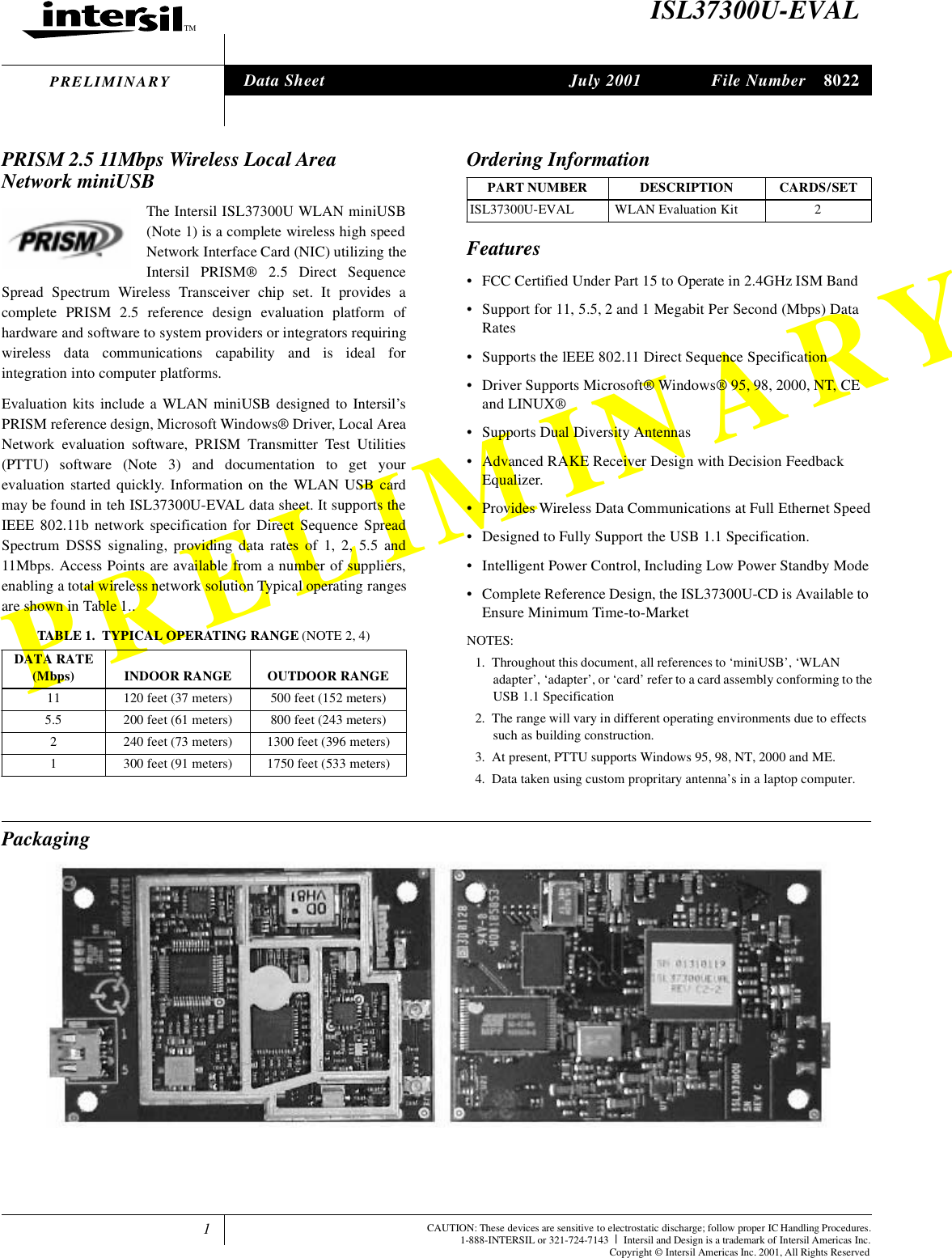
![2Functional OverviewThe WLAN miniUSB is designed to operate in the 2.4GHz ISMfrequency band, channels 1 to 11, as specified by the FCC in the USA.The Card will also operate on channels 12 to14, where permitted bylocal regulatory authorities. Radio equipment must be certified in acountry prior to use. Refer to Table 3 for a list of countries andagencies that have approved the ISL37300U-EVAL for operation.The Intersil PRISM Chip Set allows for high level integration forreduced size, increased throughput, improved radio performanceand faster time to market. The WLAN miniUSB implementsDirect Sequence Spread Spectrum DSSS technology providingsuperior noise and signal jamming immunity including less severeimpact from unintentional radiators such as microwave ovens. Theuser can connect the miniUSB in an ad-hoc peer to peernetworking scheme, allowing for instant network setup in anyoffice environment. By using an access point, the wireless LANcan be set up to allow for a greater number of users to interconnect,and to increase the coverage area. With a portal (i.e., Access Point),the wireless LAN can be easily connected into an existing wiredLAN, allowing for easy expansion of the service.Compared to the PRISM II chip set, the PRISM 2.5 generation offers:• Low loss front end designed for maximum range• Higher level of chip integration and less peripheral components to reduce material costs• Support of optional IEEE 802.11 Short Preamble for significantly increased data throughput with room for additional user defined functions.A complete Reference Design for the ISL37300U is available toensure minimum time-to-market. This information containsdetailes for manufacturing a miniUSB WLAN assembly, includingGerber PC board files, an accurate Bill of Material withcomponent sourcing and complete mechanical drawings and acomplete Radio Description and test plan. Related Literature• Tech Brief TB337, Intersil Corporation, “A Brief Tutorial on Spread Spectrum and Packet Radio”[1].• Application Note ANxxxx, Intersil Corporation, “ISL37300U-EVAL PRISM 2.5 11 Mb miniUSB Wireless LAN Radio Description” [2]• Tech Brief TB337, Intersil Corporation, “A Brief Tutorial on Spread Spectrum and Packet Radio” [3]• Tech Brief TB382, Intersil Corporation, “Measurement of WLAN Receiver Sensitivity” [4]• Application Note AN9850, Intersil Corporation, “Complementary Code Keying Made Simple” [5]• Application Note AN9829, Intersil Corporation, “Brief Tutorial on IEEE 802.11 Wireless LANs” [6]• Application Note AN9820, Intersil Corporation, “A Condensed Review of Spread Spectrum Techniques for ISM Band Systems” [7]The ISL3873 Media Access Controller (MAC) Protocol HandlerThe ISL3873 MAC/Baseband Processor and its firmware areresponsible for running the IEEE 802.11 protocol in the WLANcard. This section describes the features of IEEE 802.11 that areimplemented.The functions supported by the STA (station) Firmware are:• CSMA/CA (Carrier Sense Multiple Access with Collision Avoidance) with Random Backoff•WEP Security• Short/Long Preamble with multirate• RTS/CTS Handshake (Ready To Send/Clear To Send) and NAV Management (Network Allocation Vector)• MAC Level Acknowledgments (Media Access Control)• Re-Transmission of Unacknowledged Frames• Duplicate Detection and Rejection• Broadcast and Multicast Frames• Fragmentation and Re-Assembly• Power Management (Planned)• Timestamp Synchronization• DCF (Distributed Coordination Function)• PCF (Point Coordination Function)• Beacon Generation in an Ad-Hoc Network• Probe Response Generation in an Ad-Hoc NetworkCard Information StructureThe standard Intersil WLAN miniUSB will be supplied withinformation embedded in the Plug and Play (PnP) shown in Table2. It should be noted that in most systems this information isdisplayed when the card is inserted. Customization of the PnP forspecific customer requirements is available upon request, to enablecustomer information to be displayed when the card is inserted.TABLE 2. PnP EMBEDDED INFORMATIONFUNCTION NAME CONTENTManufacturer’s ID 00Function ID Network AdapterProduct Revision 1Manufacturer Intersil CorporationProduct 12603873PROGLOTFN8022](https://usermanual.wiki/Conexant-Systems/37300U/User-Guide-167923-Page-2.png)
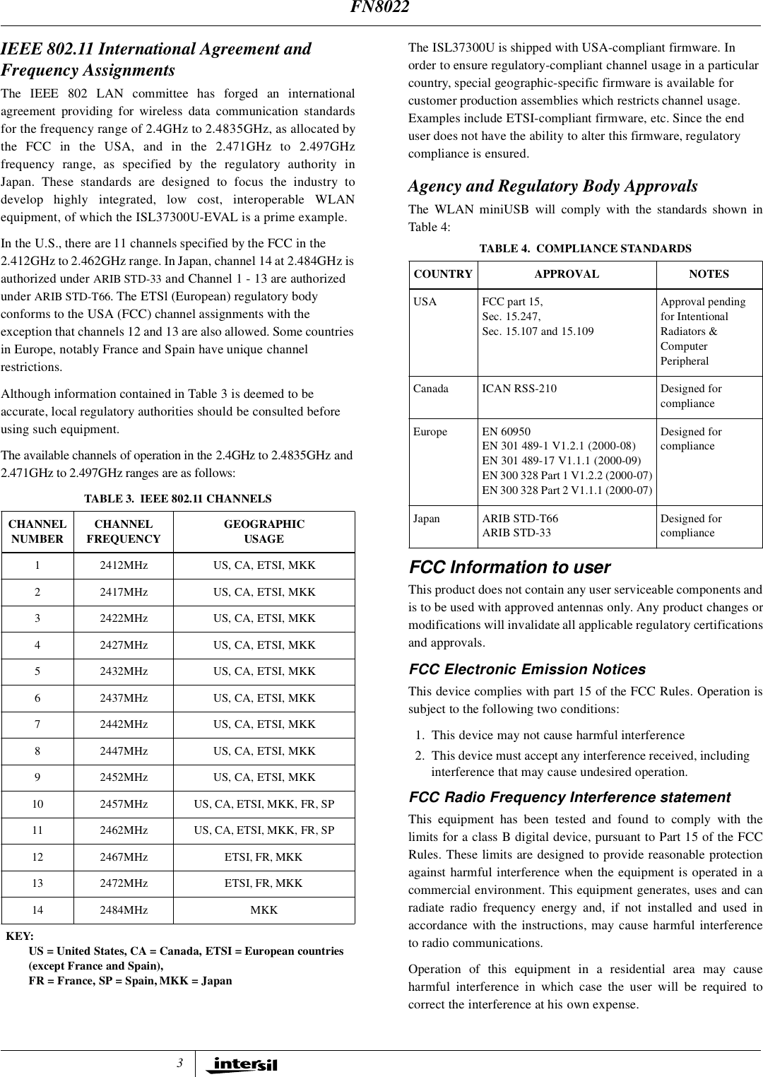
![4If this equipment does cause harmful interference to radio ortelevision reception, which can be determined by turning theequipment off and on, the user is encouraged to try to correct theinterference by one or more of the following measures:• Reorient or relocate the receiving antenna.• Increase the separation between the equipment and receiver.• Connect the equipment into an outlet on a circuit different from that to which the receiver is connected.• Consult the dealer or an experienced radio/TV technician for help.Export restrictionsThis product or software contains encryption code which may notbe exported or transferred from the US or Canada without anapproved US Department of Commerce export license.FCC Guidelines for Human ExposureCAUTION: To comply with FCC RF exposure compliance, a separation distance of at least 20 cm must be maintained between the antenna of this device and all personsThe EIRP was measured for the lower, middle and highest frequencies used by the transmitter. The results in Table 5 are based on a safe distance between antenna and operator of 8 inches.The equipment therefore fulfills the requirements on power density for general population / uncontrolled exposure of 1.0 mW/cm2 and therefore complies with the requirements of FCC part 15.247 (b) (4) and FCC OET Bulletin 65 incl. supplements A, B and C. WARNING! Any changes or modifications of equipment not expressly approved byIntersil could void the user’s authority to operate the equipment.ReferencesFor Intersil documents available on the internet, see web sitehttp://www.intersil.com/Intersil AnswerFAX (321) 724-7800.[1 ] TB337 Tech Brief, Intersil Corporation, “A Brief Tutorial on Spread Spectrum and Packet Radio”, AnswerFAX document No. 82337.[2 ] AN9951 Application Note, Intersil Corporation, “ISL37400M-EVAL PRISM 2.5 11 Mb miniUSB Wireless LAN Radio Description”[3 ] TB337 Tech Brief, Intersil Corporation, “A Brief Tutorial on Spread Spectrum and Packet Radio”[4 ] TB382 Tech Brief, Intersil Corporation, “Measurement of WLAN Receiver Sensitivity”[5 ] AN9850 Application Note, Intersil Corporation, “Complementary Code Keying Made Simple”[6 ] AN9829 Application Note, Intersil Corporation, “Brief Tutorial on IEEE 802.11 Wireless LANs”[7] AN9820 Application Note, Intersil Corporation, “A Condensed Review of Spread Spectrum Techniques for ISM Band Systems”Further information can be found in the following:• Intersil PRISM 2.5 chipset datasheets, web home page, http://www.intersil.com/design/prism/ser-p25-11mbps.asp• IEEE 802.11 Standards Project (available from the IEEE, New York, USA).TABLE 5. Power Density CalculationCh.1 Ch.6 Ch.11Measured EIRP(mW)169.8 186.2 186.2Calculated Power Density (mW/cm2)0.135 0.148 0.148FN8022](https://usermanual.wiki/Conexant-Systems/37300U/User-Guide-167923-Page-4.png)
![6All Intersil products are manufactured, assembled and tested utilizing ISO9000 quality systems.Intersil Corporation’s quality certifications can be viewed at website www.intersil.com/design/qualityIntersil products are sold by description only. Intersil Corporation reserves the right to make changes in circuit design and/or specifications at any time without notice. Accordingly, thereader is cautioned to verify that data sheets are current before placing orders. Information furnished by Intersil is believed to be accurate and reliable. However, no responsibility is assumedby Intersil or its subsidiaries for its use; nor for any infringements of patents or other rights of third parties which may result from its use. No license is granted by implication or otherwiseunder any patent or patent rights of Intersil or its subsidiaries.For information regarding Intersil Corporation and its products, see web site www.intersil.comSales Office HeadquartersNORTH AMERICAIntersil Corporation2401 Palm Bay Rd.Palm Bay, FL 32905TEL: (321) 724-7000FAX: (321) 724-7240EUROPEIntersil SAMercure Center100, Rue de la Fusee1130 Brussels, BelgiumTEL: (32) 2.724.2111FAX: (32) 2.724.22.05ASIAIntersil Ltd.8F-2, 96, Sec. 1, Chien-kuo North,Taipei, Taiwan 104Republic of ChinaTEL: 886-2-2515-8508FAX: 886-2-2515-8369Data Rate (Physical Layer) Rate - 1, 2, 5.5 and 11-MbpsNOTES:6. Refer to Application Note “PRISM Power Management Modes” AN9665 [5].7. The adjacent channel measurement is carried out on two channels separated by 25MHz (5 channels).Electrical Specifications Test Conditions: Supply Voltage (VCC) = 3.3V, Ambient Temperature (TA) = 25oC,Unless Otherwise Specified (Continued)PARAMETER SYMBOL TEST CONDITIONS MIN TYP MAX UNITSFN8022](https://usermanual.wiki/Conexant-Systems/37300U/User-Guide-167923-Page-6.png)