Conexant Systems 37300U Wireless LAN transmitter User Manual ISL37300U eval Data Sheet 31Aug2001
Conexant Systems Inc. Wireless LAN transmitter ISL37300U eval Data Sheet 31Aug2001
Manual
1
TM
PRELIMINARY
File Number 8022
CAUTION: These devices are sensitive to electrostatic discharge; follow proper IC Handling Procedures.
1-888-INTERSIL or 321-724-7143 |Intersil and Design is a trademark of Intersil Americas Inc.
Copyright © Intersil Americas Inc. 2001, All Rights Reserved
PRELIMINARY
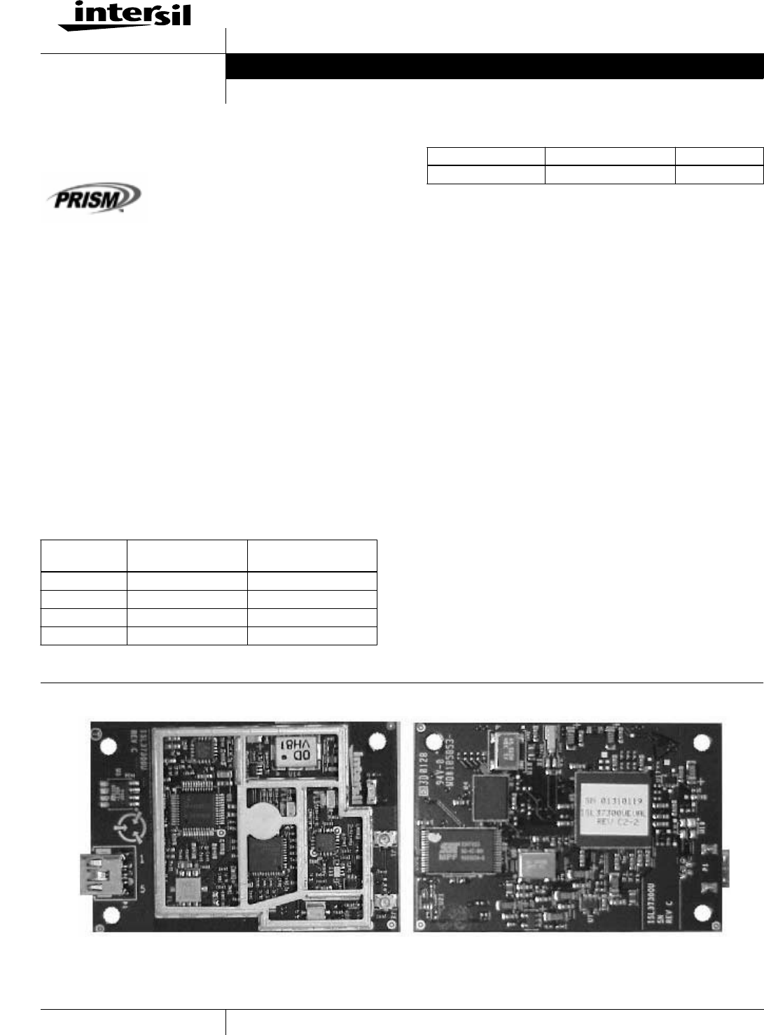
ISL37300U-EVAL
PRISM 2.5 11Mbps Wireless Local Area
Network miniUSB
The Intersil ISL37300U WLAN miniUSB
(Note 1) is a complete wireless high speed
Network Interface Card (NIC) utilizing the
Intersil PRISM® 2.5 Direct Sequence
Spread Spectrum Wireless Transceiver chip set. It provides a
complete PRISM 2.5 reference design evaluation platform of
hardware and software to system providers or integrators requiring
wireless data communications capability and is ideal for
integration into computer platforms.
Evaluation kits include a WLAN miniUSB designed to Intersil’s
PRISM reference design, Microsoft Windows® Driver, Local Area
Network evaluation software, PRISM Transmitter Test Utilities
(PTTU) software (Note 3) and documentation to get your
evaluation started quickly. Information on the WLAN USB card
may be found in teh ISL37300U-EVAL data sheet. It supports the
IEEE 802.11b network specification for Direct Sequence Spread
Spectrum DSSS signaling, providing data rates of 1, 2, 5.5 and
11Mbps. Access Points are available from a number of suppliers,
enabling a total wireless network solution Typical operating ranges
are shown in Table 1..
Features
• FCC Certified Under Part 15 to Operate in 2.4GHz ISM Band
• Support for 11, 5.5, 2 and 1 Megabit Per Second (Mbps) Data
Rates
• Supports the lEEE 802.11 Direct Sequence Specification
• Driver Supports Microsoft® Windows® 95, 98, 2000, NT, CE
and LINUX®
• Supports Dual Diversity Antennas
• Advanced RAKE Receiver Design with Decision Feedback
Equalizer.
• Provides Wireless Data Communications at Full Ethernet Speed
• Designed to Fully Support the USB 1.1 Specification.
• Intelligent Power Control, Including Low Power Standby Mode
• Complete Reference Design, the ISL37300U-CD is Available to
Ensure Minimum Time-to-Market
NOTES:
1. Throughout this document, all references to ‘miniUSB’, ‘WLAN
adapter’, ‘adapter’, or ‘card’ refer to a card assembly conforming to the
USB 1.1 Specification
2. The range will vary in different operating environments due to effects
such as building construction.
3. At present, PTTU supports Windows 95, 98, NT, 2000 and ME.
4. Data taken using custom propritary antenna’s in a laptop computer.
Packaging
TABLE 1. TYPICAL OPERATING RANGE (NOTE 2, 4)
DATA RATE
(Mbps) INDOOR RANGE OUTDOOR RANGE
11 120 feet (37 meters) 500 feet (152 meters)
5.5 200 feet (61 meters) 800 feet (243 meters)
2 240 feet (73 meters) 1300 feet (396 meters)
1 300 feet (91 meters) 1750 feet (533 meters)
Ordering Information
PART NUMBER DESCRIPTION CARDS/SET
ISL37300U-EVAL WLAN Evaluation Kit 2
Data Sheet July 2001
tle
jec
ho
w
()
ato
CI
ar
e
e
O
es
C
W
ar
2
Functional Overview
The WLAN miniUSB is designed to operate in the 2.4GHz ISM
frequency band, channels 1 to 11, as specified by the FCC in the USA.
The Card will also operate on channels 12 to14, where permitted by
local regulatory authorities. Radio equipment must be certified in a
country prior to use. Refer to Table 3 for a list of countries and
agencies that have approved the ISL37300U-EVAL for operation.
The Intersil PRISM Chip Set allows for high level integration for
reduced size, increased throughput, improved radio performance
and faster time to market. The WLAN miniUSB implements
Direct Sequence Spread Spectrum DSSS technology providing
superior noise and signal jamming immunity including less severe
impact from unintentional radiators such as microwave ovens. The
user can connect the miniUSB in an ad-hoc peer to peer
networking scheme, allowing for instant network setup in any
office environment. By using an access point, the wireless LAN
can be set up to allow for a greater number of users to interconnect,
and to increase the coverage area. With a portal (i.e., Access Point),
the wireless LAN can be easily connected into an existing wired
LAN, allowing for easy expansion of the service.
Compared to the PRISM II chip set, the PRISM 2.5 generation
offers:
• Low loss front end designed for maximum range
• Higher level of chip integration and less peripheral components
to reduce material costs
• Support of optional IEEE 802.11 Short Preamble for
significantly increased data throughput with room for additional
user defined functions.
A complete Reference Design for the ISL37300U is available to
ensure minimum time-to-market. This information contains
detailes for manufacturing a miniUSB WLAN assembly, including
Gerber PC board files, an accurate Bill of Material with
component sourcing and complete mechanical drawings and a
complete Radio Description and test plan.
Related Literature
• Tech Brief TB337, Intersil Corporation, “A Brief Tutorial on
Spread Spectrum and Packet Radio”[1].
• Application Note ANxxxx, Intersil Corporation, “ISL37300U-
EVAL PRISM 2.5 11 Mb miniUSB Wireless LAN Radio
Description” [2]
• Tech Brief TB337, Intersil Corporation, “A Brief Tutorial on
Spread Spectrum and Packet Radio” [3]
• Tech Brief TB382, Intersil Corporation, “Measurement of
WLAN Receiver Sensitivity” [4]
• Application Note AN9850, Intersil Corporation,
“Complementary Code Keying Made Simple” [5]
• Application Note AN9829, Intersil Corporation, “Brief Tutorial
on IEEE 802.11 Wireless LANs” [6]
• Application Note AN9820, Intersil Corporation, “A Condensed
Review of Spread Spectrum Techniques for ISM Band Systems”
[7]
The ISL3873 Media Access Controller (MAC)
Protocol Handler
The ISL3873 MAC/Baseband Processor and its firmware are
responsible for running the IEEE 802.11 protocol in the WLAN
card. This section describes the features of IEEE 802.11 that are
implemented.
The functions supported by the STA (station) Firmware are:
• CSMA/CA (Carrier Sense Multiple Access with Collision
Avoidance) with Random Backoff
•WEP Security
• Short/Long Preamble with multirate
• RTS/CTS Handshake (Ready To Send/Clear To Send) and NAV
Management (Network Allocation Vector)
• MAC Level Acknowledgments (Media Access Control)
• Re-Transmission of Unacknowledged Frames
• Duplicate Detection and Rejection
• Broadcast and Multicast Frames
• Fragmentation and Re-Assembly
• Power Management (Planned)
• Timestamp Synchronization
• DCF (Distributed Coordination Function)
• PCF (Point Coordination Function)
• Beacon Generation in an Ad-Hoc Network
• Probe Response Generation in an Ad-Hoc Network
Card Information Structure
The standard Intersil WLAN miniUSB will be supplied with
information embedded in the Plug and Play (PnP) shown in Table
2. It should be noted that in most systems this information is
displayed when the card is inserted. Customization of the PnP for
specific customer requirements is available upon request, to enable
customer information to be displayed when the card is inserted.
TABLE 2. PnP EMBEDDED INFORMATION
FUNCTION NAME CONTENT
Manufacturer’s ID 00
Function ID Network Adapter
Product Revision 1
Manufacturer Intersil Corporation
Product 12603873
PROG
LOT
FN8022
3
IEEE 802.11 International Agreement and
Frequency Assignments
The IEEE 802 LAN committee has forged an international
agreement providing for wireless data communication standards
for the frequency range of 2.4GHz to 2.4835GHz, as allocated by
the FCC in the USA, and in the 2.471GHz to 2.497GHz
frequency range, as specified by the regulatory authority in
Japan. These standards are designed to focus the industry to
develop highly integrated, low cost, interoperable WLAN
equipment, of which the ISL37300U-EVAL is a prime example.
In the U.S., there are 11 channels specified by the FCC in the
2.412GHz to 2.462GHz range. In Japan, channel 14 at 2.484GHz is
authorized under ARIB STD-33 and Channel 1 - 13 are authorized
under ARIB STD-T66. The ETSl (European) regulatory body
conforms to the USA (FCC) channel assignments with the
exception that channels 12 and 13 are also allowed. Some countries
in Europe, notably France and Spain have unique channel
restrictions.
Although information contained in Table 3 is deemed to be
accurate, local regulatory authorities should be consulted before
using such equipment.
The available channels of operation in the 2.4GHz to 2.4835GHz and
2.471GHz to 2.497GHz ranges are as follows:
The ISL37300U is shipped with USA-compliant firmware. In
order to ensure regulatory-compliant channel usage in a particular
country, special geographic-specific firmware is available for
customer production assemblies which restricts channel usage.
Examples include ETSI-compliant firmware, etc. Since the end
user does not have the ability to alter this firmware, regulatory
compliance is ensured.
Agency and Regulatory Body Approvals
The WLAN miniUSB will comply with the standards shown in
Table 4:
FCC Information to user
This product does not contain any user serviceable components and
is to be used with approved antennas only. Any product changes or
modifications will invalidate all applicable regulatory certifications
and approvals.
FCC Electronic Emission Notices
This device complies with part 15 of the FCC Rules. Operation is
subject to the following two conditions:
1. This device may not cause harmful interference
2. This device must accept any interference received, including
interference that may cause undesired operation.
FCC Radio Frequency Interference statement
This equipment has been tested and found to comply with the
limits for a class B digital device, pursuant to Part 15 of the FCC
Rules. These limits are designed to provide reasonable protection
against harmful interference when the equipment is operated in a
commercial environment. This equipment generates, uses and can
radiate radio frequency energy and, if not installed and used in
accordance with the instructions, may cause harmful interference
to radio communications.
Operation of this equipment in a residential area may cause
harmful interference in which case the user will be required to
correct the interference at his own expense.
TABLE 3. IEEE 802.11 CHANNELS
CHANNEL
NUMBER CHANNEL
FREQUENCY GEOGRAPHIC
USAGE
1 2412MHz US, CA, ETSI, MKK
2 2417MHz US, CA, ETSI, MKK
3 2422MHz US, CA, ETSI, MKK
4 2427MHz US, CA, ETSI, MKK
5 2432MHz US, CA, ETSI, MKK
6 2437MHz US, CA, ETSI, MKK
7 2442MHz US, CA, ETSI, MKK
8 2447MHz US, CA, ETSI, MKK
9 2452MHz US, CA, ETSI, MKK
10 2457MHz US, CA, ETSI, MKK, FR, SP
11 2462MHz US, CA, ETSI, MKK, FR, SP
12 2467MHz ETSI, FR, MKK
13 2472MHz ETSI, FR, MKK
14 2484MHz MKK
KEY:
US = United States, CA = Canada, ETSI = European countries
(except France and Spain),
FR = France, SP = Spain, MKK = Japan
TABLE 4. COMPLIANCE STANDARDS
COUNTRY APPROVAL NOTES
USA FCC part 15,
Sec. 15.247,
Sec. 15.107 and 15.109
Approval pending
for Intentional
Radiators &
Computer
Peripheral
Canada ICAN RSS-210 Designed for
compliance
Europe EN 60950
EN 301 489-1 V1.2.1 (2000-08)
EN 301 489-17 V1.1.1 (2000-09)
EN 300 328 Part 1 V1.2.2 (2000-07)
EN 300 328 Part 2 V1.1.1 (2000-07)
Designed for
compliance
Japan ARIB STD-T66
ARIB STD-33
Designed for
compliance
FN8022
4
If this equipment does cause harmful interference to radio or
television reception, which can be determined by turning the
equipment off and on, the user is encouraged to try to correct the
interference by one or more of the following measures:
• Reorient or relocate the receiving antenna.
• Increase the separation between the equipment and receiver.
• Connect the equipment into an outlet on a circuit different from
that to which the receiver is connected.
• Consult the dealer or an experienced radio/TV technician for
help.
Export restrictions
This product or software contains encryption code which may not
be exported or transferred from the US or Canada without an
approved US Department of Commerce export license.
FCC Guidelines for Human Exposure
CAUTION: To comply with FCC RF exposure
compliance, a separation distance of at least 20
cm must be maintained between the antenna of
this device and all persons
The EIRP was measured for the lower, middle and highest
frequencies used by the transmitter. The results in Table 5 are
based on a safe distance between antenna and operator of 8
inches.The equipment therefore fulfills the requirements on
power density for general population / uncontrolled exposure of
1.0 mW/cm2 and therefore complies with the requirements of
FCC part 15.247 (b) (4) and FCC OET Bulletin 65 incl.
supplements A, B and C.
WARNING! Any changes or modifications of equipment not expressly approved by
Intersil could void the user’s authority to operate the equipment.
References
For Intersil documents available on the internet, see web site
http://www.intersil.com/Intersil AnswerFAX (321) 724-7800.
[1 ] TB337 Tech Brief, Intersil Corporation, “A Brief Tutorial on
Spread Spectrum and Packet Radio”, AnswerFAX document
No. 82337.
[2 ] AN9951 Application Note, Intersil Corporation,
“ISL37400M-EVAL PRISM 2.5 11 Mb miniUSB Wireless
LAN Radio Description”
[3 ] TB337 Tech Brief, Intersil Corporation, “A Brief Tutorial on
Spread Spectrum and Packet Radio”
[4 ] TB382 Tech Brief, Intersil Corporation, “Measurement of
WLAN Receiver Sensitivity”
[5 ] AN9850 Application Note, Intersil Corporation,
“Complementary Code Keying Made Simple”
[6 ] AN9829 Application Note, Intersil Corporation, “Brief
Tutorial on IEEE 802.11 Wireless LANs”
[7] AN9820 Application Note, Intersil Corporation, “A
Condensed Review of Spread Spectrum Techniques for ISM
Band Systems”
Further information can be found in the following:
• Intersil PRISM 2.5 chipset datasheets, web home page,
http://www.intersil.com/design/prism/ser-p25-11mbps.asp
• IEEE 802.11 Standards Project (available from the IEEE,
New York, USA).
TABLE 5. Power Density Calculation
Ch.1 Ch.6 Ch.11
Measured EIRP
(mW)
169.8 186.2 186.2
Calculated Power
Density (mW/cm2)
0.135 0.148 0.148
FN8022
5
Absolute Maximum Ratings Operating Conditions
Supply Voltage . . . . . . . . . . . . . . . . . . . . . . . . . . . . . . -0.3V to 4.0V (Max)
Storage Temperature (Note 5). . . . . . . . . . . . . . . . . . . . . . . . -20oC to 85oC
Temperature Range. . . . . . . . . . . . . . . . . . . . . . . . . . . . . . 0oC ≤ TA ≤ 70oC
Supply Voltage Range. . . . . . . . . . . . . . . . . . . . . . . . . . . . . . . .3.0V to 3.6V
Caution: These are the absolute maximum ratings for the miniUSB product. Exceeding these limits could cause permanent damage to the card.
NOTE:
5. All temperature references refer to ambient conditions.
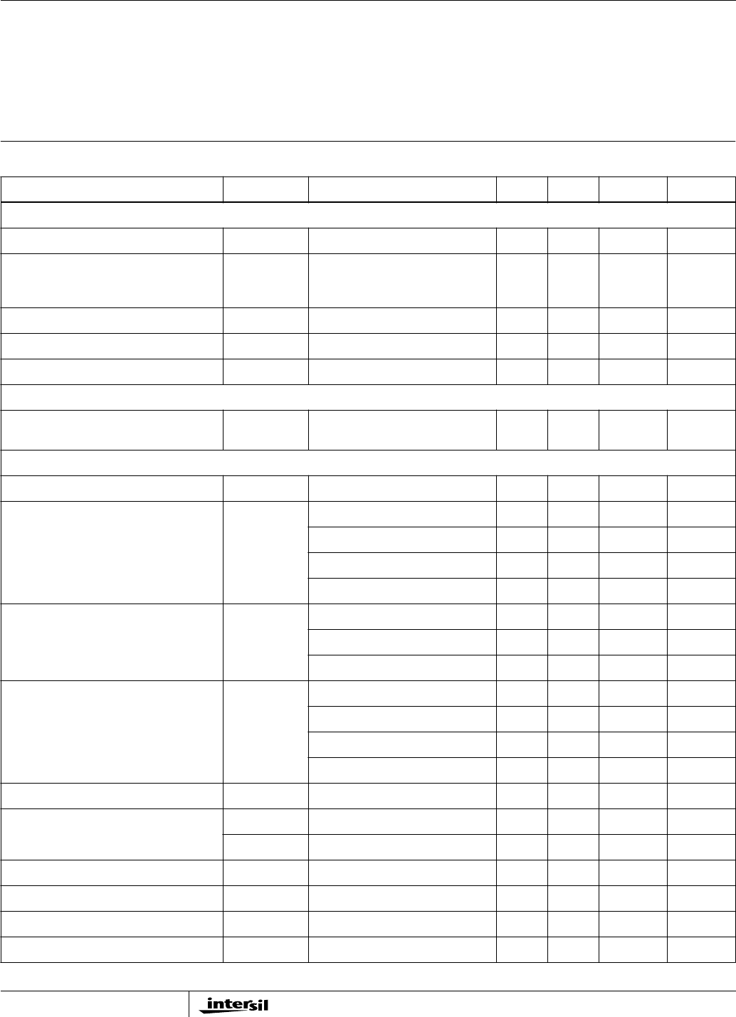
Electrical Specifications Test Conditions: Supply Voltage (VCC) = 3.3V, Ambient Temperature (T
A) = 25oC,
Unless Otherwise Specified
PARAMETER SYMBOL TEST CONDITIONS MIN TYP MAX UNITS
CURRENT CONSUMPTION
Initializatoin Current ICC -145 180 mA
Average Current
(2% TX; 8% RX; 90% Standby)
(With Power Saving Mode) (Note 6)
ICC -TBD - mA
Continuous Transmit Mode ICC -325 380 mA
Continuous Receive Mode ICC Receiving Valid Packets - 200 225 mA
Standby (Note 6) ICC -TBD - mA
miniUSB LOGIC LEVELS
Meets all electrical USB 1.1 electrical
specifications
RF SYSTEM SPECIFICATIONS
Transmitter Power Output Pout -16 - dBm
Receive Sensitivity RX_S 1Mbps, 8% PER - -90 - dBm
2Mbps, 8% PER -88 dBm
5.5Mbps, 8% PER -85 dBm
11Mbps, 8% PER - -83.5 - dBm
Multipath Delay Spread TDELAY 2Mbps, 8% PER - >290 - nSec
5.5Mbps, 8% PER 200 nSec
11Mbps, 8% PER 105 nSec
Multipath Receive Sensitivity RX_SJTC 1Mbps, 8% PER, Office B - -82 - dBm
2Mbps, 8% PER, Office B -80 dBm
5.5Mbps, 8% PER, Office A -75.4 dBm
11Mbps, 8% PER, Residential A - -71 - dBm
Maximum Receive Level RX_MAX PER <8% -3 +3 - dBm
Third Order Intercept Point (Input) IIP3_90 -90 dBm input - TBD - dBm
IIP3_25 -25 dBm input - TBD - dBm
Carrier Supression TX_sup Test Mode - -42.5 - dB
Image Rejection IR PER <8% - 60 - dB
IF Rejection IFR PER <8% 60 66.5 - dB
Adjacent Channel Rejection ACR PER <8% (Note 7) - 44.5 - dB
FN8022
6
All Intersil products are manufactured, assembled and tested utilizing ISO9000 quality systems.
Intersil Corporation’s quality certifications can be viewed at website www.intersil.com/design/quality
Intersil products are sold by description only. Intersil Corporation reserves the right to make changes in circuit design and/or specifications at any time without notice. Accordingly, the
reader is cautioned to verify that data sheets are current before placing orders. Information furnished by Intersil is believed to be accurate and reliable. However, no responsibility is assumed
by Intersil or its subsidiaries for its use; nor for any infringements of patents or other rights of third parties which may result from its use. No license is granted by implication or otherwise
under any patent or patent rights of Intersil or its subsidiaries.
For information regarding Intersil Corporation and its products, see web site www.intersil.com
Sales Office Headquarters
NORTH AMERICA
Intersil Corporation
2401 Palm Bay Rd.
Palm Bay, FL 32905
TEL: (321) 724-7000
FAX: (321) 724-7240
EUROPE
Intersil SA
Mercure Center
100, Rue de la Fusee
1130 Brussels, Belgium
TEL: (32) 2.724.2111
FAX: (32) 2.724.22.05
ASIA
Intersil Ltd.
8F-2, 96, Sec. 1, Chien-kuo North,
Taipei, Taiwan 104
Republic of China
TEL: 886-2-2515-8508
FAX: 886-2-2515-8369
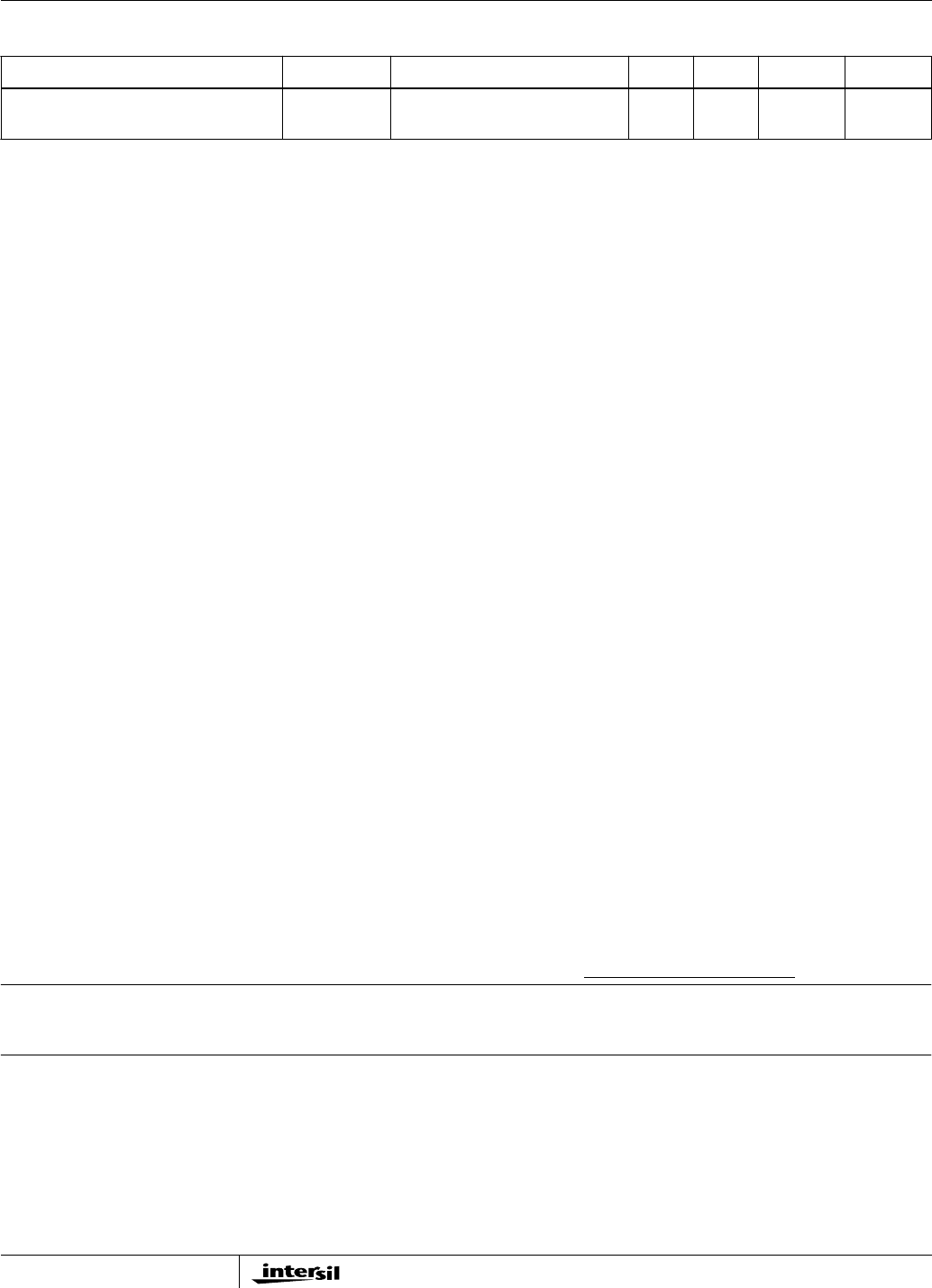
Data Rate (Physical Layer) Rate - 1, 2, 5.5
and 11
-Mbps
NOTES:
6. Refer to Application Note “PRISM Power Management Modes” AN9665 [5].
7. The adjacent channel measurement is carried out on two channels separated by 25MHz (5 channels).
Electrical Specifications Test Conditions: Supply Voltage (VCC) = 3.3V, Ambient Temperature (T
A) = 25oC,
Unless Otherwise Specified (Continued)
PARAMETER SYMBOL TEST CONDITIONS MIN TYP MAX UNITS
FN8022

7