Conexant Systems 37400M 11Mbps Wireless Local Area Network PC Card User Manual ISL37400M eval Data Sheet
Conexant Systems Inc. 11Mbps Wireless Local Area Network PC Card ISL37400M eval Data Sheet
UserManual.wiki
>
Conexant Systems
>
37400M User Manual
Extract of preliminary user manual
Navigation menu
Upload a User Manual
Namespaces
Wiki Guide
HTML
PDF
Info
Views
User Manual
Discussion / Help
Navigation
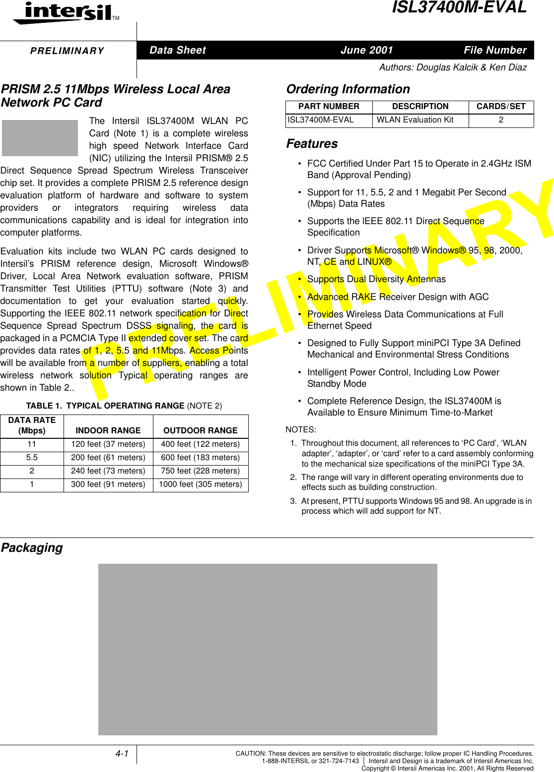
![4-2Functional OverviewThe WLAN PC Card is designed to operate in the 2.4GHz ISMfrequency band, channels 1 to 11, as specified by the FCC inthe USA. The Card will also operate on channels 12 through14, where permitted by local regulatory authorities. Radioequipment must be certified in a country prior to use. Refer toTable 3 for a list of countries and agencies that have approvedthe ISL37400M-EVAL for operation.The Intersil PRISM Chip Set allows for high level integrationfor reduced size, increased throughput, improved radioperformance and faster time to market. The WLAN PC cardimplements Direct Sequence Spread Spectrum DSSStechnology providing superior noise and signal jammingimmunity including less severe impact from unintentionalradiators such as microwave ovens. The user can connectthe PC Card in an ad-hoc peer to peer networking scheme,allowing for instant network setup in any office environment.By using an access point, the wireless LAN can be set up toallow for a greater number of users to interconnect, and toincrease the coverage area. With a portal (i.e., Access Point),the wireless LAN can be easily connected into an existingwired LAN, allowing for easy expansion of the service.Compared to the first generation PRISM II chip set, thePRISM 2.5 generation offers:• 3.3V operation for reduced power dissipation• Reduction in current drain for extended battery life• Dual antenna’s for use with Diversity circuits toimproved multipath performance• Higher level of chip integration and less peripheralcomponents to reduce material costs• Support of optional IEEE 802.11 Short Preamble forsignificantly increased data throughputA complete Reference Design for the ISL37400M isavailable to ensure minimum time-to-market. Thisinformation contains detailesfor manufacturing a miniPCIWLAN assembly, including Gerber PC board files, anaccurate Bill of Material with component sourcing andcomplete mechanical drawings.Related LiteratureTo learn more about what the IEEE 802.11 is, refer to:• Tech Brief TB337, Intersil Corporation, “A Brief Tutorialon Spread Spectrum and Packet Radio”[1].For a more detailed description of radio operation, pleaserefer to:• Application Note AN9951, Intersil Corporation,“ISL37400M-EVAL PRISM 2.5 11 Mb miniPCI WirelessLAN Radio Description” [2]The HFA3841 Media Access Controller(MAC) Protocol HandlerThe ISL3874 MAC/Baseband Processor and its firmware areresponsible for running the IEEE 802.11 protocol in theWLAN card. This section describes the features of IEEE802.11 that are implemented.The functions supported by the STA (station) Firmware are:• CSMA/CA (Carrier Sense Multiple Access withCollision Avoidance) with Random Backoff• WEP Security• Short/Long Preamble with multirate• RTS/CTS Handshake (Ready To Send/Clear To Send)and NAV Management (Network Allocation Vector)• MAC Level Acknowledgments (Media Access Control)• Re-Transmission of Unacknowledged Frames• Duplicate Detection and Rejection• Broadcast and Multicast Frames• Fragmentation and Re-Assembly• Power Management (Planned)• Timestamp Synchronization• DCF (Distributed Coordination Function)• PCF (Point Coordination Function)• Beacon Generation in an Ad-Hoc Network• Probe Response Generation in an Ad-Hoc NetworkCard Information StructureThe standard Intersil WLAN PC Card will be supplied withinformation embedded in the CIS shown in Table 2. It shouldbe noted that in most systems this information is displayedwhen the card is inserted. Customization of the CIS forspecific customer requirements is available upon request, toenable customer information to be displayed when the cardis inserted.TABLE 2. CIS EMBEDDED INFORMATIONFUNCTION NAME CONTENTManufacturer’s ID 00Function ID Network AdapterProduct Revision 1Manufacturer Intersil CorporationProduct HFA3841PROGLOT](https://usermanual.wiki/Conexant-Systems/37400M/User-Guide-157160-Page-2.png)
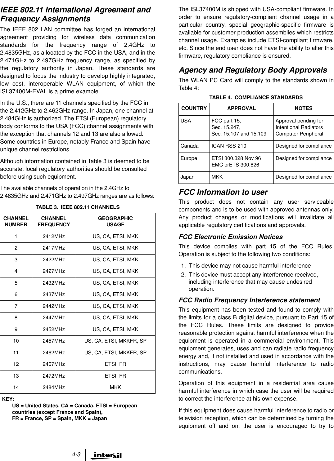
![4-4correct the interference by one or more of the followingmeasures:• Reorient or relocate the receiving antenna.• Increase the separation between the equipment andreceiver.• Connect the equipment into an outlet on a circuitdifferent from that to which the receiver is connected.• Consult the dealer or an experienced radio/TVtechnician for help.Export restrictionsThis product or software contains encryption code whichmay not be exported or transferred from the US or Canadawithout an approved US Department of Commerce exportlicense.FCC Guidelines for Human ExposureThe EIRP was measured for the lower, middle and highestfrequencies used by the transmitter. The results in Table 5are based on a safe distance between antenna andoperator of 8 inches.The equipment therefore fulfills therequirements on power density for general population /uncontrolled exposure and therefore complies with therequirements of FCC part 15.247 (b) (4) and FCC OETBulletin 65 incl. supplements A, B and C.WARNING! Any changes or modifications of equipment not expresslyapproved by Intersil could void the user’s authority to operate the equipment.3.3V miniPCI Interface StandardCAUTION: This assembly is designed to operate with asupply voltage of 3.3V in laptop computers supporting thedminiPCI standard. As such, it is mechanically keyed toprevent improper insertion in laptops. Do not therefore forceengagement of the card in the miniPCI slot of the laptop.Permanent damage may occur if operated outside of thespecified limits listed in this document.ReferencesFor Intersil documents available on the internet, see web sitehttp://www.intersil.com/Intersil AnswerFAX (321) 724-7800.[1] TB337 Tech Brief, Intersil Corporation, “A Brief Tutorialon Spread Spectrum and Packet Radio”, AnswerFAXdocument No. 82337.[2] AN9951 Application Note, Intersil Corporation,“ISL37400M-EVAL PRISM 2.5 11 Mb miniPCI WirelessLAN Radio Description”Further information can be found in the following:• Intersil PRISM 2.5 datasheets, web home page,http://www.intersil.com/design/prism/ser-p25-11mbps.asp• IEEE 802.11 Standards Project (available from theIEEE, New York, USA).TABLE 5. Power Density CalculationCh.1 Ch.6 Ch.11Measured EIRP(mW66.1 67.6 64.6Calculated PowerDensity (mW/cm2)0.052 0.053 0.051](https://usermanual.wiki/Conexant-Systems/37400M/User-Guide-157160-Page-4.png)
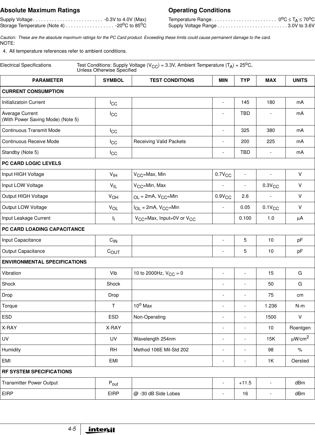
![4-6All Intersil products are manufactured, assembled and tested utilizing ISO9000 quality systems.Intersil Corporation’s quality certifications can be viewed at website www.intersil.com/design/qualityIntersil products are sold by description only. Intersil Corporation reserves the right to make changes in circuit design and/or specifications at any time without notice.Accordingly, the reader is cautioned to verify that data sheets are current before placing orders. Information furnished by Intersil is believed to be accurate and reliable. How-ever, no responsibility is assumed by Intersil or its subsidiaries for its use; nor for any infringements of patents or other rights of third parties which may result from its use. Nolicense is granted by implication or otherwise under any patent or patent rights of Intersil or its subsidiaries.For information regarding Intersil Corporation and its products, see web site www.intersil.comSales Office HeadquartersNORTH AMERICAIntersil Corporation2401 Palm Bay Rd.Palm Bay, FL 32905TEL: (321) 724-7000FAX: (321) 724-7240EUROPEIntersil SAMercure Center100, Rue de la Fusee1130 Brussels, BelgiumTEL: (32) 2.724.2111FAX: (32) 2.724.22.05ASIAIntersil Ltd.8F-2, 96, Sec. 1, Chien-kuo North,Taipei, Taiwan 104Republic of ChinaTEL: 886-2-2515-8508FAX: 886-2-2515-8369Receive Sensitivity RX_S 5.5Mbps, 8% PER - -88 - dBm11Mbps, 8% PER - -84 - dBmMaximum Receive Level RX_MAX PER <8% -4 - - dBmThird Order Intercept Point (Input) IIP3_90 -90 dBm input - TBD - dBmIIP3_25 -25 dBm input - TBD - dBmCarrier Supression TX_sup Test Mode - -42.5 - dBImage Rejection IR PER <8% - 60 - dBIF Rejection IFR PER <8% 60 66.5 - dBAdjacent Channel Rejection ACR PER <8% (Note 6) - 60 - dBData Rate (Physical Layer) Rate - 1, 2, 5.5and 11- MbpsNOTES:5. Refer to Application Note “PRISM Power Management Modes” AN9665 [5].6. The adjacent channel measurement is carried out on two channels separated by 25MHz (5 channels).Electrical Specifications Test Conditions: Supply Voltage (VCC) = 3.3V, Ambient Temperature (TA)=25oC,Unless Otherwise Specified (Continued)PARAMETER SYMBOL TEST CONDITIONS MIN TYP MAX UNITS](https://usermanual.wiki/Conexant-Systems/37400M/User-Guide-157160-Page-6.png)