Connect One SMG2N1 Nano wiReach 2nd Generation 802.11b/g/n (BRD-SMG2N1) User Manual Release Notes
Connect One Ltd. Nano wiReach 2nd Generation 802.11b/g/n (BRD-SMG2N1) Release Notes
UserManual.wiki
>
Connect One
>
SMG2N1 User Manual
User manual
Navigation menu
Upload a User Manual
Namespaces
Wiki Guide
HTML
PDF
Info
Views
User Manual
Discussion / Help
Navigation
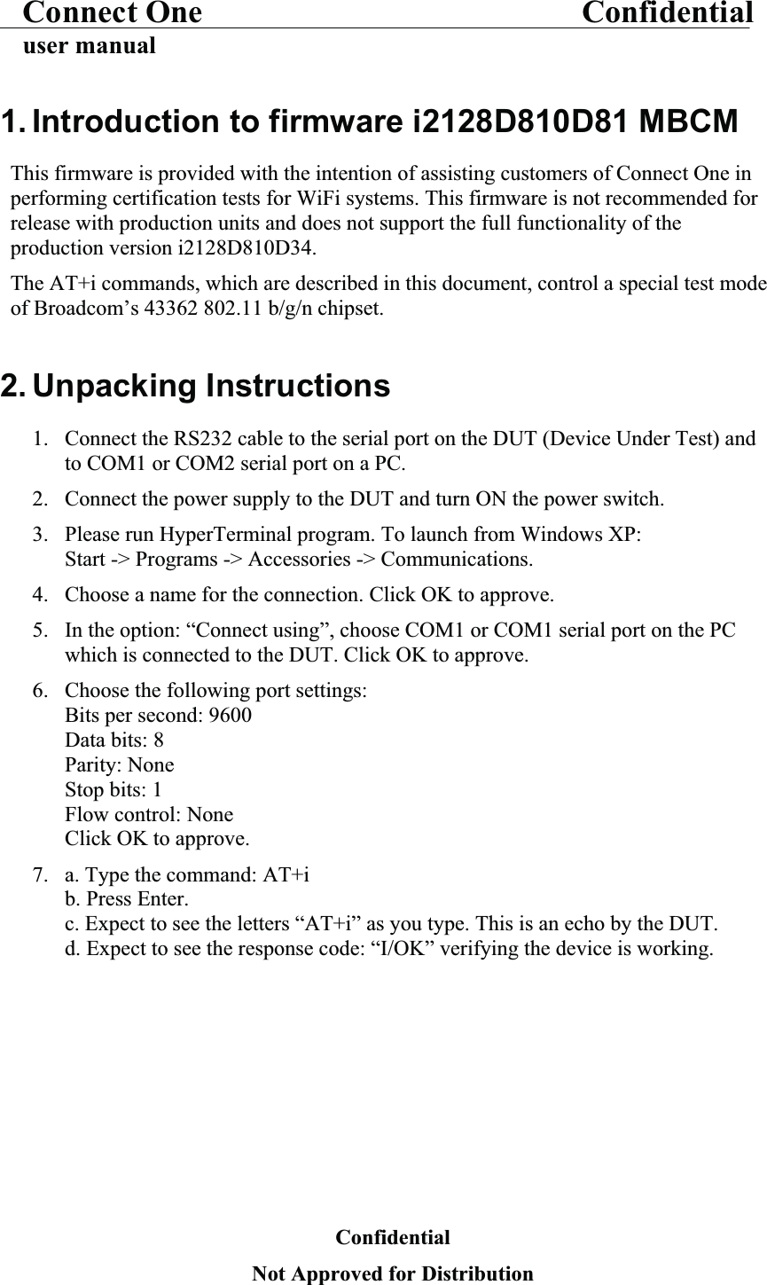
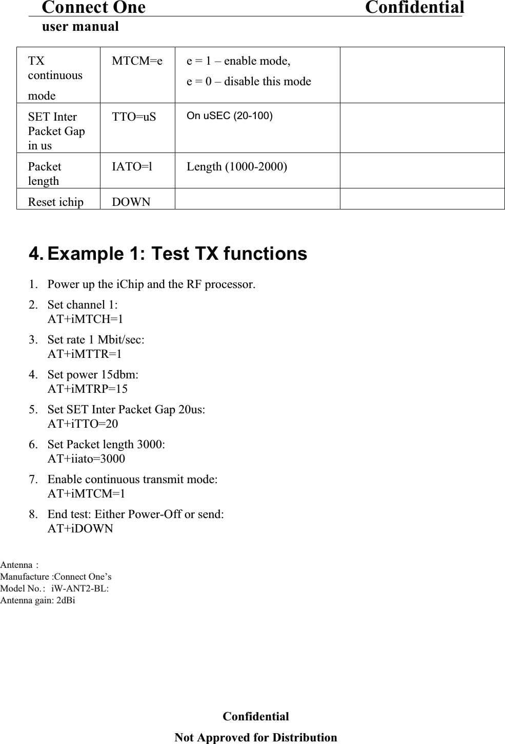
![Connect One Confidentialuser manual3. AT+i CommandsTest AT+i Commandparameters descriptionSet RF channelMTCH=x x = [1-14] X= channel 1 - 14Set TX rate MTTR=r r = 1 for 1 mbps, r = 2 for 2mbps, r =5 for 5.5 mbps, r = 11 for 11 mbps,r = 6 for 6 mbps,r = 9 for 9 mbps,r = 12 for 12 mbps,r = 16 for 18 mbps,r = 24 for 24 mbps,r = 36 for 36 mbps,r = 12 for 48 mbps,r = 54 for 54 mbpsr= 100 for MCS0r= 101 for MCS1r= 102 for MCS2r= 103 for MCS3r= 104 for MCS4r= 105 for MCS5r= 106 for MCS6r= 107 for MCS7Set Power at AntennaMTRP=p p = power in dbm [10 - 15]TX Carrier Wave continuous modeMTCW=e e = 0 – disable this mode e = 1 – enable mode,Transmits only the carrier signal, continuously.To end the test: MTCW = 0.ConfidentialNot Approved for Distribution](https://usermanual.wiki/Connect-One/SMG2N1/User-Guide-2380957-Page-4.png)