Connect One SMG2N1 Nano wiReach 2nd Generation 802.11b/g/n (BRD-SMG2N1) User Manual Release Notes
Connect One Ltd. Nano wiReach 2nd Generation 802.11b/g/n (BRD-SMG2N1) Release Notes
User manual

Connect One Confidential
user manual
August 2014
iChip OS Version i2128D810D34 MBCM
Manufacturer’s Firmware for use in Certification Testing
560 S. Winchester Blvd. 20 Atir Yeda Street
Suite 500 1st floor
San Jose, CA 95128 Kfar Saba 44643 Israel
Tel: +1 (408) 572-5675 Tel: +972-9-766-0456
Fax: +1 (408) 572-5601 Fax: +972-9-766-0461
www.connectone.com
Confidential
Not Approved for Distribution

Connect One Confidential
user manual
Table of Contents
1. INTRODUCTION TO FIRMWARE I2128D810D81 MBCM ..................................................... 3
2. UNPACKING INSTRUCTIONS ................................................................................................ 3
3. AT+I COMMANDS .................................................................................................................... 4
4. EXAMPLE 1: TEST TX FUNCTIONS ....................................................................................... 5
5. IN CASE OF FAILURE .............................................................................................................. 6
Confidential
Not Approved for Distribution

Connect One Confidential
user manual
1. Introduction to firmware i2128D810D81 MBCM
This firmware is provided with the intention of assisting customers of Connect One in
performing certification tests for WiFi systems. This firmware is not recommended for
release with production units and does not support the full functionality of the
production version i2128D810D34.
The AT+i commands, which are described in this document, control a special test mode
of Broadcom’s 43362 802.11 b/g/n chipset.
2. Unpacking Instructions
1. Connect the RS232 cable to the serial port on the DUT (Device Under Test) and
to COM1 or COM2 serial port on a PC.
2. Connect the power supply to the DUT and turn ON the power switch.
3. Please run HyperTerminal program. To launch from Windows XP:
Start -> Programs -> Accessories -> Communications.
4. Choose a name for the connection. Click OK to approve.
5. In the option: “Connect using”, choose COM1 or COM1 serial port on the PC
which is connected to the DUT. Click OK to approve.
6. Choose the following port settings:
Bits per second: 9600
Data bits: 8
Parity: None
Stop bits: 1
Flow control: None
Click OK to approve.
7. a. Type the command: AT+i
b. Press Enter.
c. Expect to see the letters “AT+i” as you type. This is an echo by the DUT.
d. Expect to see the response code: “I/OK” verifying the device is working.
Confidential
Not Approved for Distribution

Connect One Confidential
user manual
3. AT+i Commands
Test AT+i
Command
parameters description
Set RF
channel
MTCH=x x = [1-14] X= channel 1 - 14
Set TX rate MTTR=r r = 1 for 1 mbps,
r = 2 for 2mbps,
r =5 for 5.5 mbps,
r = 11 for 11 mbps,
r = 6 for 6 mbps,
r = 9 for 9 mbps,
r = 12 for 12 mbps,
r = 16 for 18 mbps,
r = 24 for 24 mbps,
r = 36 for 36 mbps,
r = 12 for 48 mbps,
r = 54 for 54 mbps
r= 100 for MCS0
r= 101 for MCS1
r= 102 for MCS2
r= 103 for MCS3
r= 104 for MCS4
r= 105 for MCS5
r= 106 for MCS6
r= 107 for MCS7
Set Power at
Antenna
MTRP=p p = power in dbm [10 - 15]
TX Carrier
Wave
continuous
mode
MTCW=e e = 0 – disable this mode
e = 1 – enable mode,
Transmits only the carrier
signal, continuously.
To end the test: MTCW = 0.
Confidential
Not Approved for Distribution

Connect One Confidential
user manual
TX
continuous
mode
MTCM=e e = 1 – enable mode,
e = 0 – disable this mode
SET Inter
Packet Gap
in us
TTO=uS On uSEC (20-100)
Packet
length
IATO=l Length (1000-2000)
Reset ichip DOWN
4. Example 1: Test TX functions
1. Power up the iChip and the RF processor.
2. Set channel 1:
AT+iMTCH=1
3. Set rate 1 Mbit/sec:
AT+iMTTR=1
4. Set power 15dbm:
AT+iMTRP=15
5. Set SET Inter Packet Gap 20us:
AT+iTTO=20
6. Set Packet length 3000:
AT+iiato=3000
7. Enable continuous transmit mode:
AT+iMTCM=1
8. End test: Either Power-Off or send:
AT+iDOWN
Confidential
Not Approved for Distribution
A
ntennas: Air Wave (EA-79F); Tekfun C. (M04-SR); YC Communication (Q24-24W); Pulse (W1030). Maximum Gain all: 2dBi.
Antenna :
Manufacture :Connect One’s
Model No.:iW-ANT2-BL:
Antenna gain: 2dBi

Connect One Confidential
user manual
5. In Case of Failure
Please contact our technical support via email: support@connectone.com
Alternatively, call the office in Israel: +972-9-766-0456
FCC Statement
This device complies with part 15 of the FCC Rules. Operation is subject to the
following two conditions: (1) This device may not cause harmful interference, and (2)
this device must accept any interference received, including interference that may cause
undesired operation.
Changes or modifications not expressly approved by the party responsible for
compliance could void the user's authority to operate the equipment.
FCC Radiation Exposure Statement
The modular can be installed or integrated in mobile or fix devices only. This modular
cannot be installed in any portable device, for example, USB dongle like transmitters is
forbidden.
This modular complies with FCC RF radiation exposure limits set forth for an
uncontrolled environment. This transmitter must not be co-located or operating in
conjunction with any other antenna or transmitter. This modular must be installed and
operated with a minimum distance of 20 cm between the radiator and user body.
If the FCC identification number is not visible when the module is installed inside
another device, then the outside of the device into which the module is installed must
also display a label referring to the enclosed module. This exterior label can use wording
such as the following: “Contains Transmitter Module FCC ID:
when the module is installed inside another device, the user manual of this device must
contain below warning statements;
1. This device complies with Part 15 of the FCC Rules. Operation is subject to the
following two conditions:
(1) This device may not cause harmful interference.
(2) This device must accept any interference received, including interference that may
cause undesired operation.
2. Changes or modifications not expressly approved by the party responsible for
compliance could void the user's authority to operate the equipment.
The devices must be installed and used in strict accordance with the manufacturer's
instructions as describe
Confidential
Not Approved for Distribution
FCC ID: XM5-SMG2N1"

Connect One Confidential
user manual
IC STATEMENT
This device complies with Industry Canada licence-exempt RSS standard(s). Operation
is subject to the following two conditions: (1) this device may not cause interference,
and (2) this device must accept any interference, including interference that may cause
undesired operation of the device.
Le présent appareil est conforme aux CNR d'Industrie Canada applicables aux appareils
radio exempts de licence. L'exploitation est autorisée aux deux conditions suivantes : (1)
l'appareil ne doit pas produire de brouillage, et (2) l'utilisateur de l'appareil doit accepter
tout brouillage radioélectrique subi, même si le brouillage est susceptible d'en
compromettre le fonctionnement.
Confidential
Not Approved for Distribution
Le modulaire peut être intégrée ou installée dans les appareils mobiles ou fixes seulement. Cette
modulaire ne peut être installé dans n'importe quel appareil portable, par exemple, dongle USB
comme émetteurs est interdit.
Cette modulaire conforme aux RF IC limites d'exposition aux rayonnements définies pour un
environnement non contrôlé. Cet émetteur ne doit pas être co-localisées ou opérant en
conjonction avec une autre antenne ou émetteur. Cette modulaire doit être installé et utilisé à une
distance minimum de 20 cm entre le radiateur et le corps de l'utilisateur.
Si le nombre IC n'est pas visible lorsque le module est installé à l'intérieur d'un autre appareil,
p
uis l'extérieur de l'appareil dans lequel le module est installé, il doit également afficher une
étiquette de renvoi vers le module fermé. Cette étiquette extérieure peut utiliser une formulation
telle que la suivante: Contient IC: 8516A-SMG2N1
The modular can be installed or integrated in mobile or fix devices only. This modular
cannot be installed in any portable device, for example, USB dongle like transmitters is
forbidden.
This modular complies with IC RF radiation exposure limits set forth for an uncontrolled
environment. This transmitter must not be co-located or operating in conjunction with any
other antenna or transmitter. This modular must be installed and operated with a minimum
distance of 20 cm between the radiator and user body.
If the IC number is not visible when the module is installed inside another device, then the
outside of the device into which the module is installed must also display a label referring to
the enclosed module. This exterior label can use wording such as the following: Contains
IC:8516A-SMG2N1
when the module is installed inside another device, the user manual of this device must
contain below warning statements:
This device complies with Industry Canada licence-exempt RSS standard(s). Operation is subjec
t
to the following two conditions: (1) this device may not cause interference, and (2) this device
must accept any interference, including interference that may cause undesired operation of the
device.
Le présent appareil est conforme aux CNR d'Industrie Canada applicables aux appareils radio
exempts de licence. L'exploitation est autorisée aux deux conditions suivantes : (1) l'appareil ne
doit pas produire de brouillage, et (2) l'utilisateur de l'appareil doit accepter tout brouillage
radioélectrique subi, même si le brouillage est susceptible d'en compromettre le fonctionnement.
Nano WiReach G2 N1 – Preliminary Datasheet
14
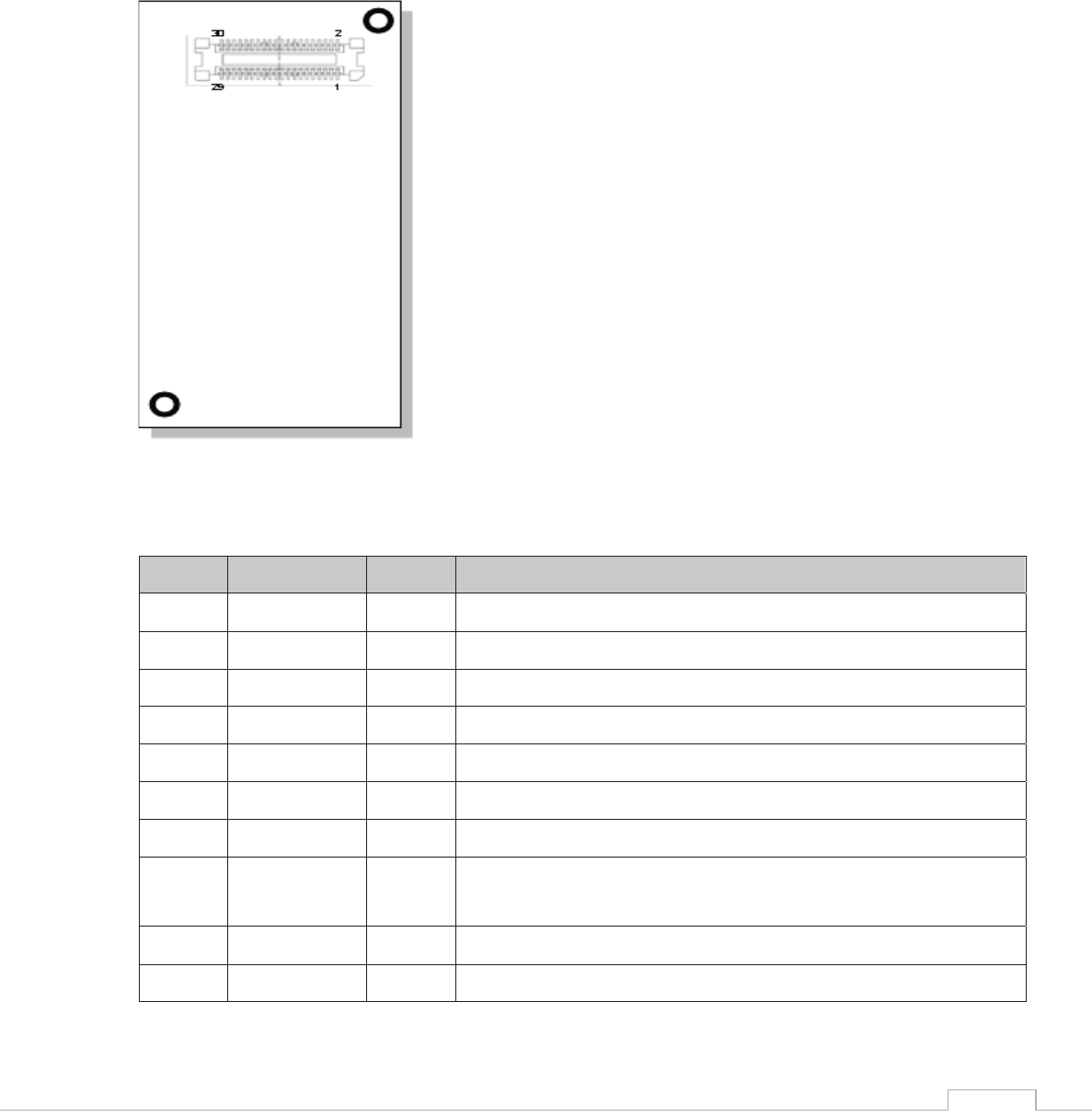
Connector: Molex 53748-0308
Mate with:
Molex 52991-0308
5. Layout and Pin Description
1) Layout
2) Pin Functional Description
Pin
Signal
Type
Description
1
VDD
Power
2
GND
Power
3
RXD0
Input
UART 0 receive
4
TXD0
Output
UART 0 Transmit
5
nCTS0
Input
UART 0 clear to send
6
nRTS0
Output
UART 0 request to send
7
DATA_RDY
Output
Data ready. Signals incoming Internet data.
8
MSEL
Input
Mode select. Used for inducing rescue mode and forced local
FW
-update.
9
nRESET
Input
Reset Module
10
nRF_LED
Output
RF LED indicator

Nano WiReach G2 N1 – Preliminary Datasheet
15
11
nSPI1_CS
Input
SPI 1 chip select for host
12
SPI1_CLK
Input
SPI 1 clock for host (Max 12MHz)
13
SPI1_MISO
Output
SPI 1 slave out for host master in
14
SPI1_MOSI
Input
SPI 1 slave in for host master out
15
SPI1_INT
Output
SPI 1 have data on his buffer
16
Readiness
Output
iChip Ready status line. See AT+I programmers manual.
17
DDP
Analog
USB device positive
18
DDM
Analog
USB device negative
19
VDD
Power
20
GND
Power
21
ETX_EN
Output
RMII Transmit Enable
22
RMII-REFCLK
Input
RMII Reference Clock
23
CRSDV
Input
RMII Carrier sense and Data Valid
24
ERXER
Input
RMII Receive Error
25
EMDIO
I/O
Management data I/O
26
EMDC
Output
Management data Clock
27
ETX1
Output
RMII transmit Data 1
28
ERX1
Input
RMII Receive Data 1
29
ERX0
Input
RMII Receive Data 0
30
ERX0
Input
RMII Receive Data 0
Nano WiReach G2 N1 – Preliminary Datasheet
16
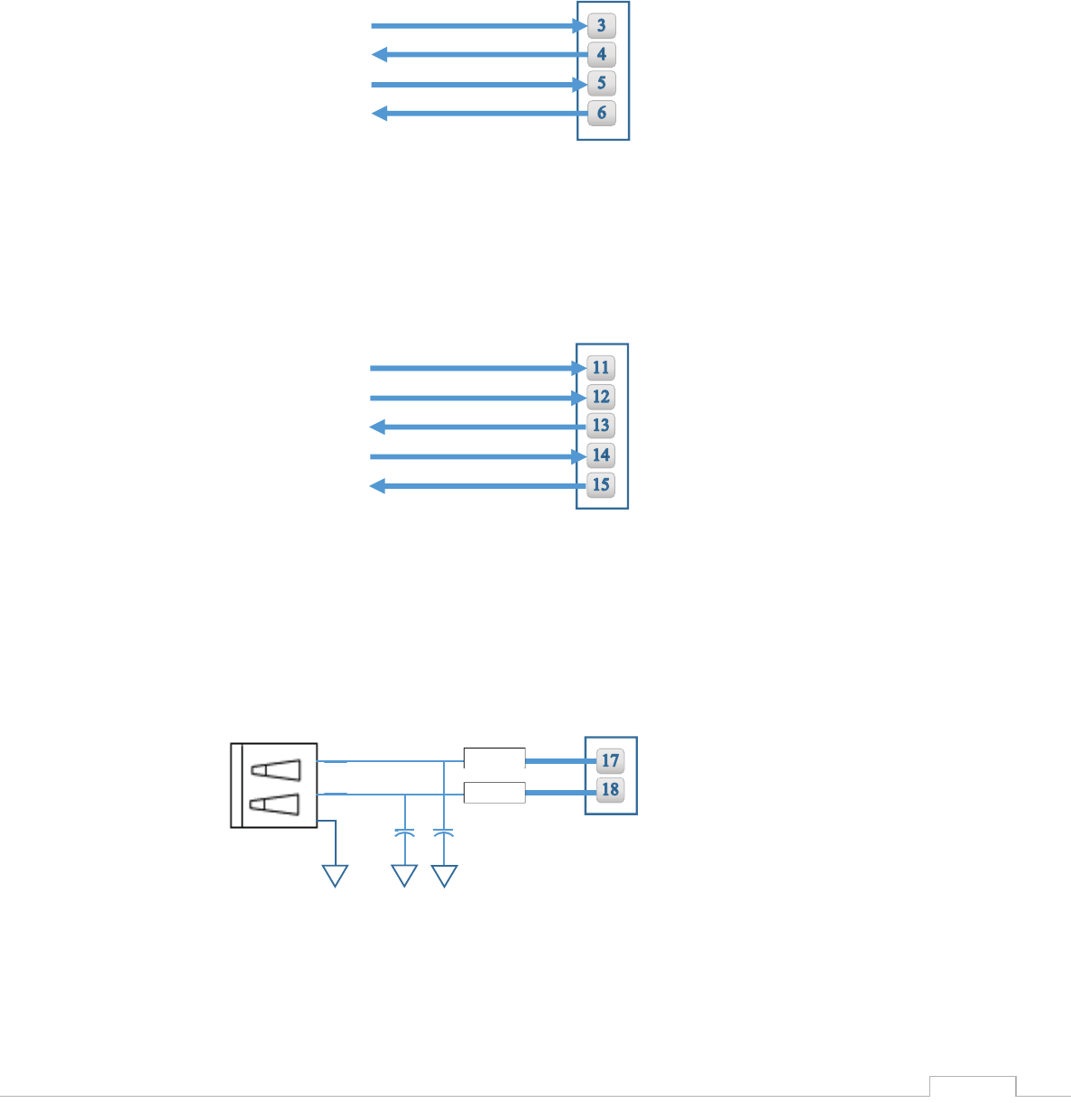
6. Interfaces
1) Serial Interface
2) SPI Interface
3) USB 2.0 Device Interface
RXD0
TXD0
nCTS0
nRTS0
Nano G2 N1 Connector
nSPI1 CS
SPI1 CLK
SPI1 MISO
SPI1 MOSI
Nano G2 N1 Connector
SPI1 INT
Nano G2 N1 Connector
USB B
27Ω
27Ω
15pF
15pF
3
2
4
Nano WiReach G2 N1 – Preliminary Datasheet
17
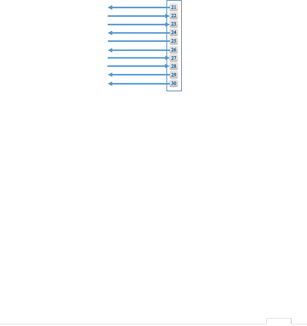
4) RMII Interface
ETX EN
REF CLK
Nano G2 N1 Connector
CRSDV
ERXER
EMDIO
EMDC
ERX0
ERX1
ETX0
ETX1
Nano WiReach G2 N1 – Preliminary Datasheet
18
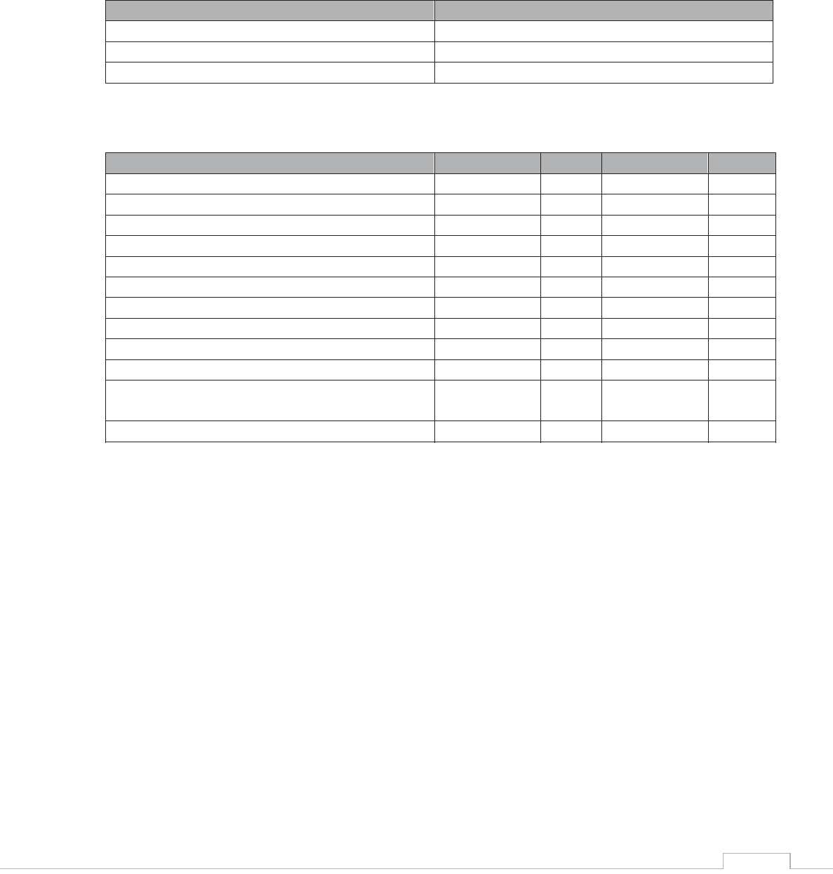
7. Electrical Specifications
1) Absolute Maximum Ratings
Parameter
Rating
Voltage at any pin with respect to ground
-0.3V to +3.6V
Operating Temperature
-30⁰C to +85⁰C -22⁰F to +185⁰F
Storage Temperature
-40⁰C to +85⁰C -40⁰F to +185⁰F
2) DC Operating Characteristics
Parameter
Min
Typical
Max
Units
VDD
3.0
3.3
3.6
Volts
High Level Input
2.0
VDD I/O +0.3
Volts
Low Level Input
-0.3
0.8
Volts
High Level Output @2mA
VDD I/O -0.4
Volts
High Level Output @0mA
VDD I/O-0.2
Volts
Low Level Output @2mA
0.4
Volts
Low Level Output @0mA
0.2
Volts
Input Leakage Current
10
μA
Power Supply Current from VDD (Tx. Mode)
350
mA
Power Supply Current from VDD (Rcv. Mode)
130
mA
Power Supply Current from VDD (Power Save
Mode)
TBD
mA
Input Capacitance
5.3
pF
Radio Frequency Range
2.412
2.484
GHz