Connect One SMG2SMT BRD-SMG2SMT-xx User Manual
Connect One Ltd. BRD-SMG2SMT-xx
UserManual.wiki
>
Connect One
>
SMG2SMT User Manual
User manual
Navigation menu
Upload a User Manual
Namespaces
Wiki Guide
HTML
PDF
Info
Views
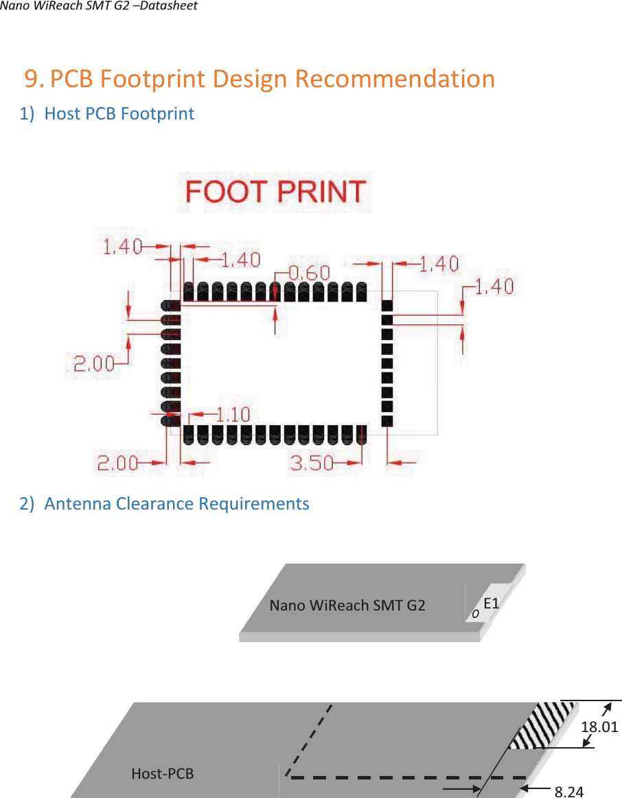
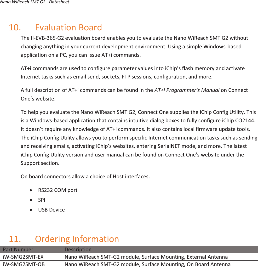
User Manual
Discussion / Help
Navigation