Connect One SMG2SMT BRD-SMG2SMT-xx User Manual
Connect One Ltd. BRD-SMG2SMT-xx
User manual
Connect One Ltd. 20 Atir Yeda Street, Kfar Saba 44643, Israel | Phone: +972-9-766-0456 | Fax: +972-9-766-0461 Email: sales@connectone.com | www.connectone.com
Datasheet
Nano WiReach SMT-G2
Version 1.1.2

Nano WiReach SMT G2 –Datasheet
3
iChip, Nano WiReach SMT G2, IP Communication Controller, SerialNET, AT+i and Connect One are
trademarks of Connect One Ltd. Copyright 2014 Connect One Ltd. All rights reserved.
This device complies with part 15 of the FCC Rules. Operation is subject to the following two conditions: (1) This device may not cause harmful
interference, and (2) this device must accept any interference received, including interference that may cause undesired operation.
Changes or modifications not expressly approved by the party responsible for compliance could void the user's authority to operate the equipment.
N
OTE: This equipment has been tested and found to comply with the limits for a Class B digital device, pursuant to Part 15 of the FCC Rules.
These limits are designed to provide reasonable protection against harmful interference in a residential installation. This equipment generates, uses
and can radiate radio frequency energy and, if not installed and used in accordance with the instructions, may cause harmful interference to radio
communications. However, there is no guarantee that interference will not occur in a particular installation. If this equipment does cause harmful
interference to radio or television reception, which can be determined by turning the equipment off and on, the user is encouraged to try to correct
the interference by one or more of the following
measures:
-- Reorient or relocate the receiving antenna.
-- Increase the separation between the equipment and receiver.
-- Connect the equipment into an outlet on a circuit different from that to which the receiver is connected.
-- Consult the dealer or an experienced radio/TV technician for help.
F
CC Radiation Exposure Statement
The modular can be installed or integrated in mobile or fix devices only. This modular cannot be installed in any portable device, for example, USB
dongle like transmitters is forbidden.
This modular complies with FCC RF radiation exposure limits set forth for an uncontrolled environment. This transmitter must not be co-located or
operating in conjunction with any other antenna or transmitter. This modular must be installed and operated with a minimum distance of 20 cm
between the radiator and user body.
I
f the FCC identification number is not visible when the module is installed inside another device, then the outside of the device into which the
module is installed must also display a label referring to the enclosed module. This exterior label can use wording such as the following: “Contains
Transmitter Module FCC ID:XM5-SMG2SMT
when the module is installed inside another device, the user manual of this device must contain below warning statements;
1. This device complies with Part 15 of the FCC Rules. Operation is subject to the following two conditions:
(1) This device may not cause harmful interference.
(2) This device must accept any interference received, including interference that may cause undesired operation.
2. Changes or modifications not expressly approved by the party responsible for compliance could void the user's authority to operate the
equipment.
The devices must be installed and used in strict accordance with the manufacturer's instructions as described in the user documentation that comes
with the product.
or Contains FCC ID:XM5-SMG2SMT
This device complies with Industry Canada licence-exempt RSS standard(s). Operation is subject to the following two
conditions: (1) this device may not cause interference, and (2) this device must accept any interference, including interference
that may cause undesired operation of the device.
This modular complies with RSS-102 radiation exposure limits set forth for an uncontrolled environment.
This modular must be installed and operated with a minimum distance of 20 cm between the radiator and user body.
Le présent appareil est conforme aux CNR d'Industrie Canada applicables aux appareils radio exempts de licence. L'exploitation
est autorisée aux deux conditions suivantes : (1) l'appareil ne doit pas produire de brouillage, et (2) l'utilisateur de l'appareil
doit accepter tout brouillage radioélectrique subi, même si le brouillage est susceptible d'en compromettre le fonctionnement.
If the IC identification number is not visible when the module is installed inside another device, then the outside of the device
into which the module is installed must also display a label referring to the enclosed module. This exterior label can use
wording such as the following: “Contains IC: 8516A-SMG2SMT ”
when the module is installed inside another device, the user manual of this device must contain below warning statements;
1˅This device complies with Industry Canada licence-exempt RSS standard(s). Operation is subject to the following two
conditions: (1) this device may not cause interference, and (2) this device must accept any interference, including interference
that may cause undesired operation of the device.
2˅Le présent appareil est conforme aux CNR d'Industrie Canada applicables aux appareils radio exempts de licence.
L'exploitation est autorisée aux deux conditions suivantes : (1) l'appareil ne doit pas produire de brouillage, et (2) l'utilisateur
de l'appareil doit accepter tout brouillage radioélectrique subi, même si le brouillage est susceptible d'en compromettre le
fonctionnement.

Nano WiReach SMT G2 –Datasheet
4
Table of Contents
Revision History .................................................................................................................................................... 6
1. Introduction ................................................................................................................................................... 7
2) General Description .................................................................................................................................. 7
3) Hardware Description ............................................................................................................................... 9
4) Performance Specifications ...................................................................................................................... 9
5) Internet Protocols ..................................................................................................................................... 9
6) Security Protocols ..................................................................................................................................... 9
7) Application Program Interface (API) ......................................................................................................... 9
8) Wireless Specifications ........................................................................................................................... 10
9) Recommended Antenna ......................................................................................................................... 10
10) Certification ........................................................................................................................................ 10
11) Installation Requirements .................................................................................................................. 11
2. Features ....................................................................................................................................................... 11
1) Security ................................................................................................................................................... 11
2) Protocols ................................................................................................................................................. 11
3) Additional Features ................................................................................................................................. 11
3. Typical Applications ..................................................................................................................................... 12
4. AT+i Command Set ...................................................................................................................................... 13
5. Layout and Pin Description .......................................................................................................................... 14
1) Layout ..................................................................................................................................................... 14
2) Pin Functional Description ...................................................................................................................... 14
6. Interfaces ..................................................................................................................................................... 16
1) Serial Interface ........................................................................................................................................ 16
2) SPI Interface ............................................................................................................................................ 16
3) USB 2.0 Device Interface ........................................................................................................................ 16
4) RMII Interface ......................................................................................................................................... 17
5) USB 2.0 Host Interface ............................................................................................................................ 17

Nano WiReach SMT G2 –Datasheet
5
7. Electrical Specifications ............................................................................................................................... 18
1) Absolute Maximum Ratings .................................................................................................................... 18
2) DC Operating Characteristics .................................................................................................................. 18
3) AC Operating Characteristics .................................................................................................................. 19
4) Transmit Specification ............................................................................................................................ 19
5) Receive Specifications............................................................................................................................. 19
6) On Board Antenna .................................................................................................................................. 20
8. Mechanical Dimensions............................................................................................................................... 21
9. PCB Footprint Design Recommendation ..................................................................................................... 22
1) Host PCB Footprint ................................................................................................................................. 22
2) Antenna Clearance Requirements .......................................................................................................... 22
10. Evaluation Board ..................................................................................................................................... 23
11. Ordering Information .............................................................................................................................. 23
Appendix A - Internet Protocol Compliance ....................................................................................................... 24
Appendix B – AT+I Configuration Examples ....................................................................................................... 25
Automatically connect to a specific Access Point:.............................................................................. 25
Create an Access Point to allow connection from mobile devices: ................................................... 25
LAN – WiFi switch mode - merges Ethernet station(s) with WiFi client(s) into one logical subnet ... 25
Appendix C – Soldering Profile ........................................................................................................................... 27

Nano WiReach SMT G2 –Datasheet
6
Revision History
Version
Date
Description
1.0
May 14th 2014
Initial preliminary version
1.1
May 21st 2014
Adding AT+i commands examples
1.1.1
July 7th 2014
Updating security features
1.1.2
July 31, 2014
Typo fix

Nano WiReach SMT G2 –Datasheet
7
1. Introduction
2) General Description
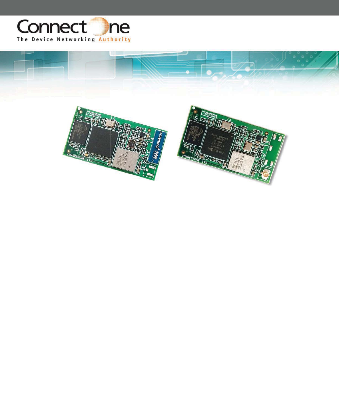
Nano WiReach™ SMT G2 is a secure serial-to-Wireless-LAN device module that can perform as a
WLAN client or Access Point to connect serial devices to 802.11b/g/n Wireless LANs. It includes the
iChip™ CO2144 IP Communication Controller™ chip and Broadcom BCM43362 WiFi chipset. It is
packaged in RoHS-compliant ultra-slim form factor and uses an industry standard pin-out. The Nano
WiReach SMT G2 can also be interfaced to a 10/100BaseT wired LAN and a USB cellular modem
with some external components and glue logic.
Nano WiReach SMT G2 offers and supports large variety of features which among them:
x Ten simultaneous TCP/UDP sockets
x Two listening sockets
x Webserver with two websites
x SMTP and POP3 clients
x DHCP client/server
x POP3 SMTP client with MIME attachment
x FTP client
x TELNET client
x SerialNET™ mode for serial to IP bridging
x Gateway between a local network on it’s LAN/WLAN interfaces and a WAN on any of
it’s other interfaces
x Switch between it’s WLAN interface and the Ethernet interface when acting as a WLAN
access point
x An Ethernet to WiFi bridge to connect an ETH client to a WiFi network (cable
replacement)
x Security gap between the application and the network
Nano WiReach SMT G2 supports the SSL3/TLS1 protocol for secure sockets, HTTPS, FTPS and secure
web server. On the WLAN interface it supports: WEP, WPA and WPA2 WiFi encryption.
Nano WiReach SMT G2 minimizes the need to redesign the host device hardware. It features a
standard economical SMT footprint providing for low-cost placement on a host PCB with provisions
for an on-board or external antenna. Minimal or no software configuration is needed for Nano
WiReach SMT G2 to access the Wireless LAN.

Nano WiReach SMT G2 –Datasheet
8
Connect One’s high-level AT+i™ API eliminates the need to add WiFi drivers, security and
networking protocols and tasks to the host application. The AT+i SerialNET operating mode offers a
true plug-and-play mode that eliminates any changes to the host application.
Nano WiReach SMT G2 firmware – the IP stack and Internet configuration parameters – are stored
in an external FLASH memory.
The II-EVB-365-G2 evaluation board provides an easy environment for testing the Nano WiReach
SMT G2 prior to designing it into your product.

Nano WiReach SMT G2 –Datasheet
9
3) Hardware Description
Size: 37.0 x 20.0 x 2.5 mm
Core CPU: 32-bit RISC ARM7TDMI,
Low-leakage, 0.13 micron, at 48MHz
Operating Voltage: +3.3V+/-10%
Operating Humidity: 90% maximum (non-condensing)
Operating Temperature Range: -30°C to +85°C
-22°F to 185°F
Power Consumption (max): Transmit – 350mA@11Mbps, 310mA@54Mbps,
310mA@72Mbps
Receive – 130mA
Antenna: On-Board or U.FL RF Connector
Connection: 44 SMT pads
Host Interface: Serial, SPI, USB Device
A/D Input
Cellular Modem Interface: USB Host
10/100 Base T LAN Interface: RMII (w/ext. PHY)
4) Performance Specifications
Host Data Rate: Up to 3Mbps in serial mode
Serial Data Format (AT+i mode): Asynchronous character; binary; 8 data bits; no parity; 1 stop bit
SerialNET mode: Asynchronous character; binary; 7 or 8 data bits; odd, even, or
no parity; 1 stop bit
Flow Control: Hardware (-RTS, -CTS) and software flow control.
5) Internet Protocols
ARP, ICMP, IP, UDP, TCP, DHCP, DNS, NTP, SMTP, POP3, MIME, HTTP, FTP and TELNET
6) Security Protocols
SSL3/TLS1, HTTPS, FTPS, RSA, AES-128/256, 3DES, RC-4, SHA-1, MD-5, WEP, WPA and WPA2
Accelerated in HW: AES, 3DEC and SHA
7) Application Program Interface (API)
Connect One’s AT+i protocol

Nano WiReach SMT G2 –Datasheet
10
8) Wireless Specifications
Standards supported: IEEE 802.11b/g/n
Frequency: Europe: 2.412-2.472GHz
USA: 2.412-2.462GHz
Japan: 2.412–2.484GHz
Channels: Europe: 13 channels
USA: 11 channels
Japan: 14 channels
9) Approved External Antenna
Connect One’s iW-ANT2-BL: 2.4GHz, 2.0dBi, 50Ω, Omni-directional, 1/4 wavelength
Dipole configuration, VSWR≤2.0
Height - 82.5mm, Weight – 6.3 grams
10) Certification
The below is pending certification approval
Radio & EMC:
USA
FCC Modular Approval
CFR Title 47 FCC Part 15, Subpart B and C
Canada
Industry Canada Module Approval
Industry Canada ICES-003, RSS-Gen, RSS-210
EU
EN 300 328
EN 301 489
Safety:
UL 60950
CAN/CSA-C22.2 No. 60950
EN 60950, Low Voltage Directive
THIS DEVICE COMPLIES WITH PART 15 OF THE FCC RULES. OPERATION IS SUBJECT TO THE FOLLOWING TWO
CONDITIONS: (1) THIS DEVICE MAY NOT CAUSE HARMFUL INTERFERENCE, AND (2) THIS DEVICE MUST ACCEPT ANY
INTERFERENCE RECEIVED, INCLUDING INTERFERENCE THAT MAY CAUSE UNDESIRED OPERATION. THE MANUFACTURER
IS NOT RESPONSIBLE FOR ANY RADIO OR TV INTERFERENCE CAUSED BY UNAUTHORIZED MODIFICATIONS TO THIS
EQUIPMENT. SUCH MODIFICATIONS COULD VOID THE USER’S AUTHORITY TO OPERATE THE EQUIPMENT
The on-board antenna is from Antenova, part number: 30 30 A5887 – 01 antenna gain 2.1dBi

Nano WiReach SMT G2 –Datasheet
11
11) Installation Requirements
The Nano WiReach SMT must be installed within a full-enclosure device that is safety certified.
2. Features
1) Security
Acts as a security gap between the host application and the network
One secure SSL3/TLS1 socket
Provides WEP, WPA and WPA2 Wireless LAN security
Supports multiple Certificate Authorities and both client-side and server-side authentication
Secure FTP and HTTP clients (over SSL3)
Secure Web Server
Includes a true hardware random number generator
AES, 3DES and SHA accelerated in hardware
2) Protocols
Up to 10 simultaneous TCP/UDP sockets and two listening sockets
HTTP client
HTTP web server with two on-chip websites: configuration site and application site
FTP and TELNET clients
DHCP client and server
POP3 or SMTP client allows sending and receiving textual and binary email with MIME attachments
3) Additional Features
Supports infrastructure Wireless LAN networks
SerialNET mode for serial-to-IP bridging (port server mode)
Local firmware update
Remote configuration and firmware update over the Internet
Note: For a detailed description of all available features, see the AT+i Programmer’s Manual.
Nano WiReach SMT G2 –Datasheet
12
3. Typical Applications
Adding IP communications over WiFi to serial embedded devices.
Replacing a LAN cable with a WiFi connection.
Adding SSL security to M2M solutions.
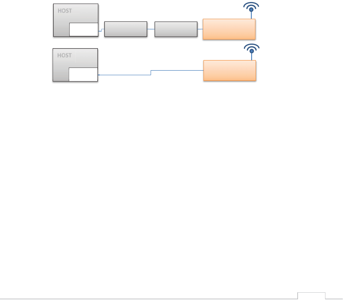
LAN to WiFi Bridge - allowing transparent bridging of LAN client over WiFi (Cable replacement),
using direct RMII connection to existing MAC hardware or direct PHY-to-PHY connection.
SerialNetTM Serial to WiFi Bridge - allowing transparent bridging of Serial over WiFi, using a 3Mbps
fast UART. This is a true plug-and-play mode that eliminates any changes to the host application.
PPP modem emulation – allowing existing (i.e. modem) designs currently using PPP to connect
transparently over WiFi.
Full Internet Controller mode – allowing simple MCU to use the Nano WiReach SMT’s rich protocol
and application capabilities to perform complex Internet operations such as E-mail, FTP, SSL,
embedded Web server and others. It also acts as a firewall, providing a security gap between the
application and the network.
HOST
EMAC
Ethernet
Ethernet
SMT-G2
SMT-G2
MAC to MAC
RMII
PHY to PHY
HOST
EMAC
Nano WiReach SMT G2 –Datasheet
13
LAN
Ù
Cellular / WiFi
Ù
Cellular / LAN
Ù
WiFi / WiFi
Ù
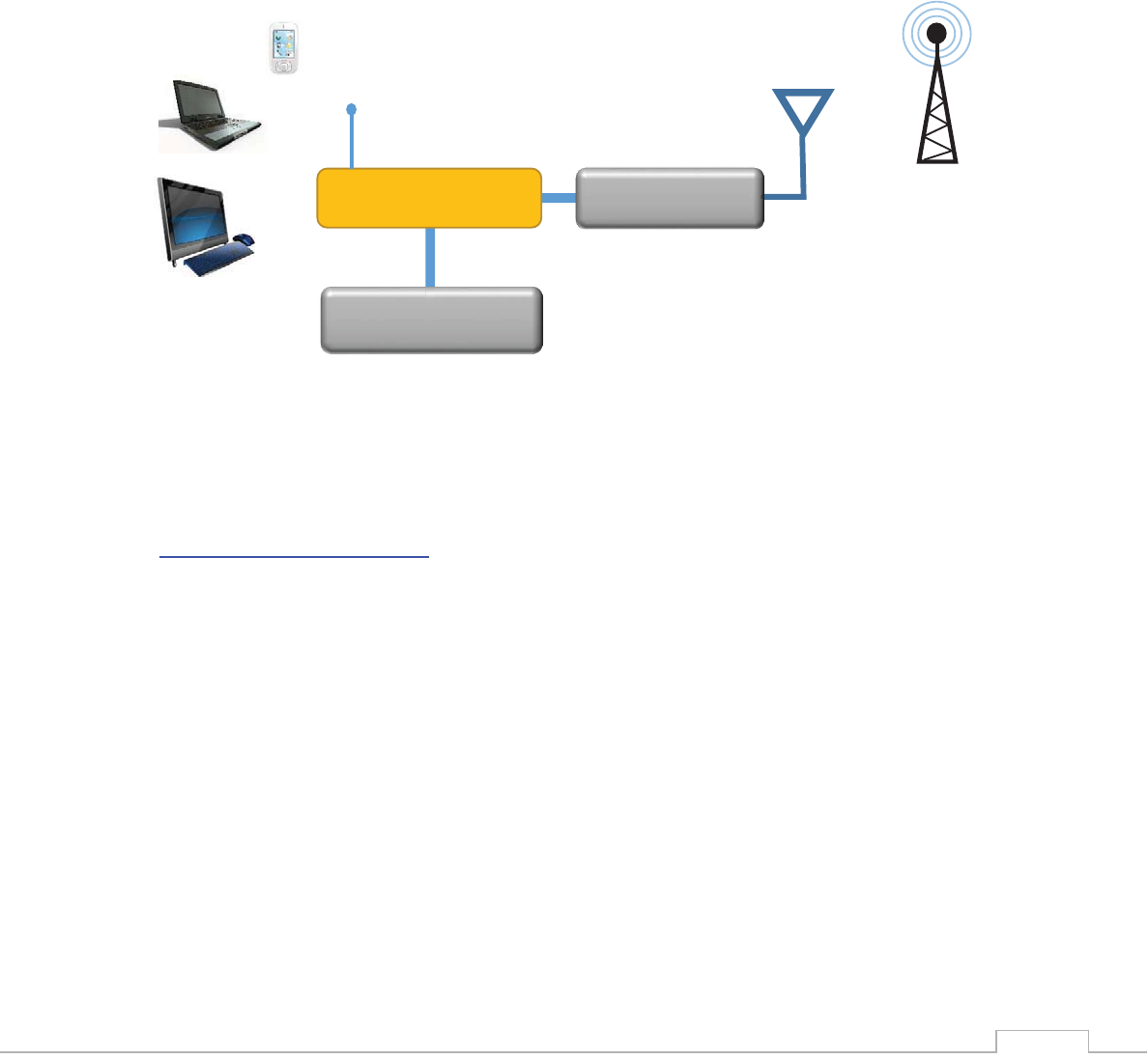
LAN Gateway – allowing local systems,
communicating over LAN and/or WiFi, to gain WAN access to the Internet. The WAN can be
implemented using cellular modem / WiFi / LAN. A user configurable parameter allows the WAN to
be configured to one of the iChip network interfaces. This mode includes a DHCP server and NAT to
support multiple local systems communicating over a single cellular link.
4. AT+i Command Set
The iW-SMG2SMT is configured and controlled using proprietary AT+i protocol. You can create a
quick configuration using our AT+i Configuration Wizard located in Connect One’s website
http://www.connectone.com. In addition, the AT+i Programmer's Manual includes commends
description and format of the entire AT+i command set.
Please refer to Appendix B for examples of module configuration using AT+i command set.
HOST Computer
IW-SMG2SMT
Cellular Modem
Nano WiReach SMT G2 –Datasheet
14
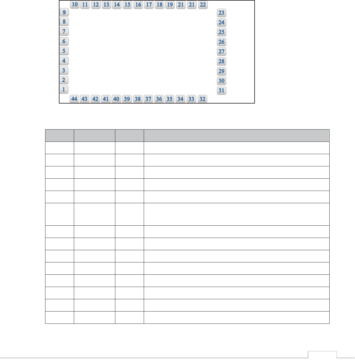
Bottom View
5. Layout and Pin Description
1) Layout
2) Pin Functional Description
Pin
Signal
Type
Description
1
GND
Power
2
HDM
Analog
USB Host negative
3
HDP
Analog
USB Host positive
4
nRESET
Input
Reset Module. Pull LOW for 100mSec to Reset
5
PIOC4
I/O
General In/Output Port
6
MSEL
Input
Mode select. Used for inducing rescue mode and forced local
FW
-update.
7
DATA_RDY
Output
Data ready. Signals incoming Internet data.
8
ETX_EN
Output
RMII Transmit Enable
9
REFCLK
Input
RMII Reference Clock 50Mhz
10
ETX0
Output
RMII transmit Data 0
11
ETX1
Output
RMII transmit Data 1
12
CRSDV
Input
RMII Carrier sense and Data Valid
13
ERX0
Input
RMII Receive Data 0
14
ERX1
Input
RMII Receive Data 1

Nano WiReach SMT G2 –Datasheet
15
15
ERXER
Input
RMII Receive Error
16
EMDC
Output
Management data Clock
17
EMDIO
I/O
Management data I/O
18
PIOC5
I/O
General In/Output Port
19
VBUS
Output
VBUS for USB Host
20
Readiness
Output
iChip Ready status line. See AT+I programmers manual.
21
PIOC3
I/O
General In/Output Port
22
VDD
Power
3.3V
23-31
GND
Power
32
nRF_LED
Output
RF LED indicator
33
ACH
Input
Analog Input
34
SPI1_CLK
Input
SPI 1 clock for host (Max 12MHz)
35
nSPI1_CS
Input
SPI 1 chip select for host
36
SPI1_MISO
Output
SPI 1 slave out for host master in
37
SPI1_MOSI
Input
SPI 1 slave in for host master out
38
SPI1_INT
Output
SPI 1 have data on his buffer
39
TXD0
Output
UART 0 transmit
40
RXD0
Input
UART 0 receive
41
nCTS0
Input
UART 0 clear to send
42
nRTS0
Output
UART 0 request to send
43
DDM
Analog
USB device negative
44
DDP
Analog
USB device positive
Nano WiReach SMT G2 –Datasheet
16
6. Interfaces
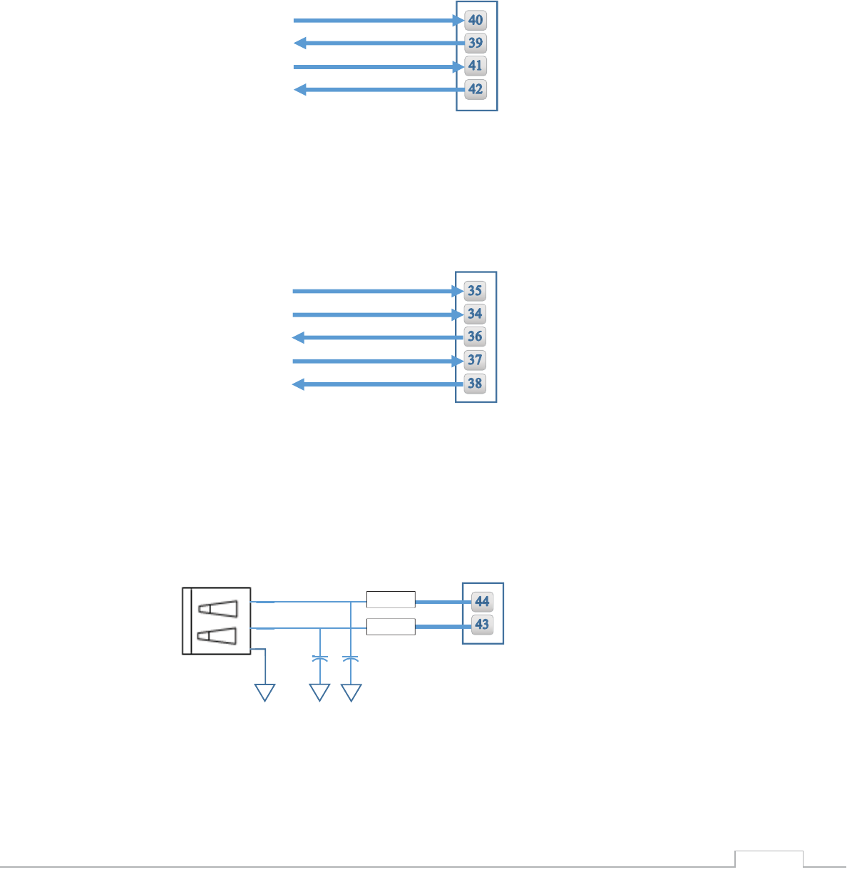
1) Serial Interface
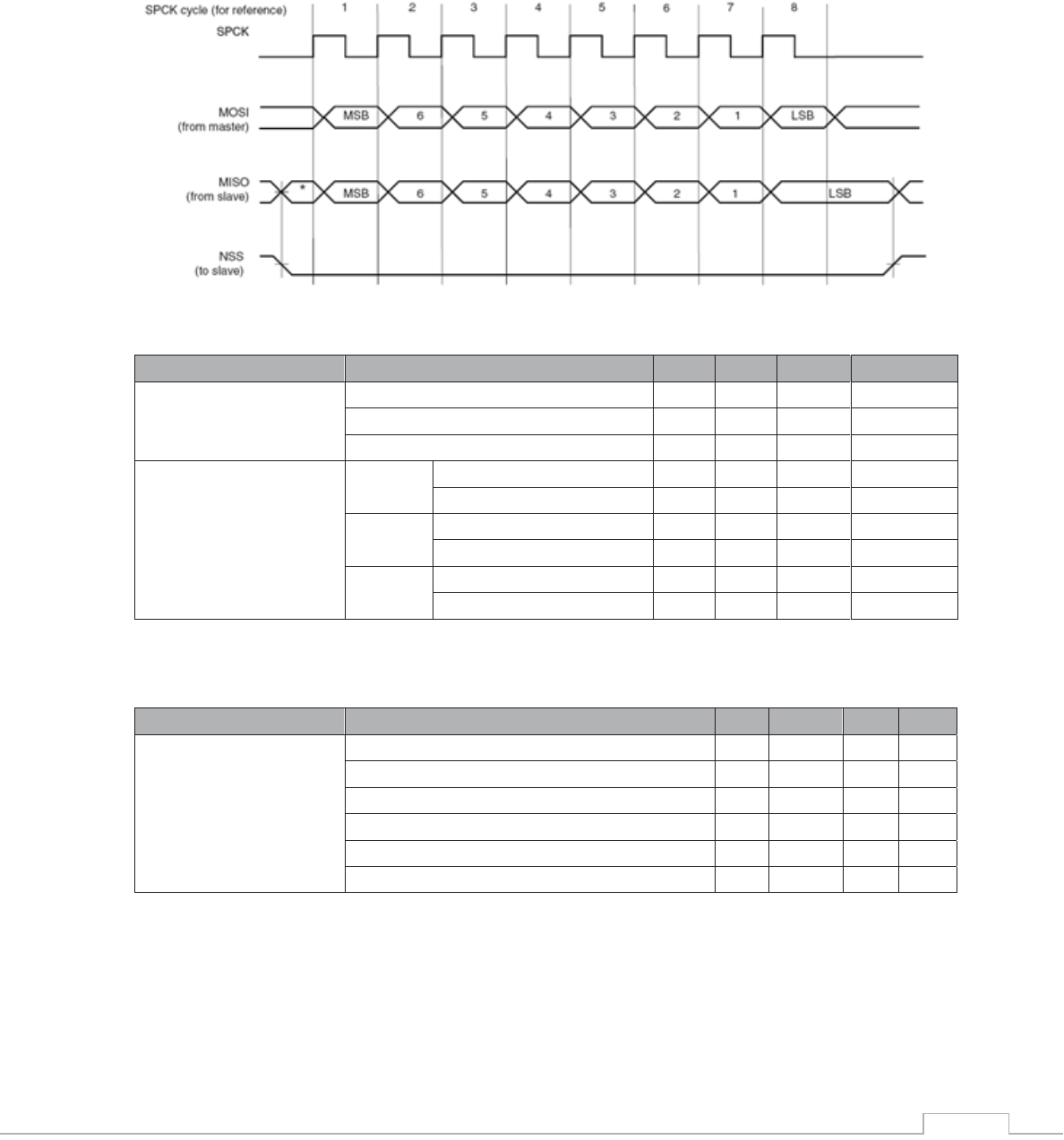
2) SPI Interface
3) USB 2.0 Device Interface
RXD0
TXD0
nCTS0
nRTS0
Nano SMT G2 Pins
nSPI1 CS
SPI1 CLK
SPI1 MISO
SPI1 MOSI
Nano SMT G2 Pins
SPI1 INT
Nano SMT G2 Pins
USB B
27Ω
27Ω
15pF
15pF
3
2
4
Nano WiReach SMT G2 –Datasheet
17
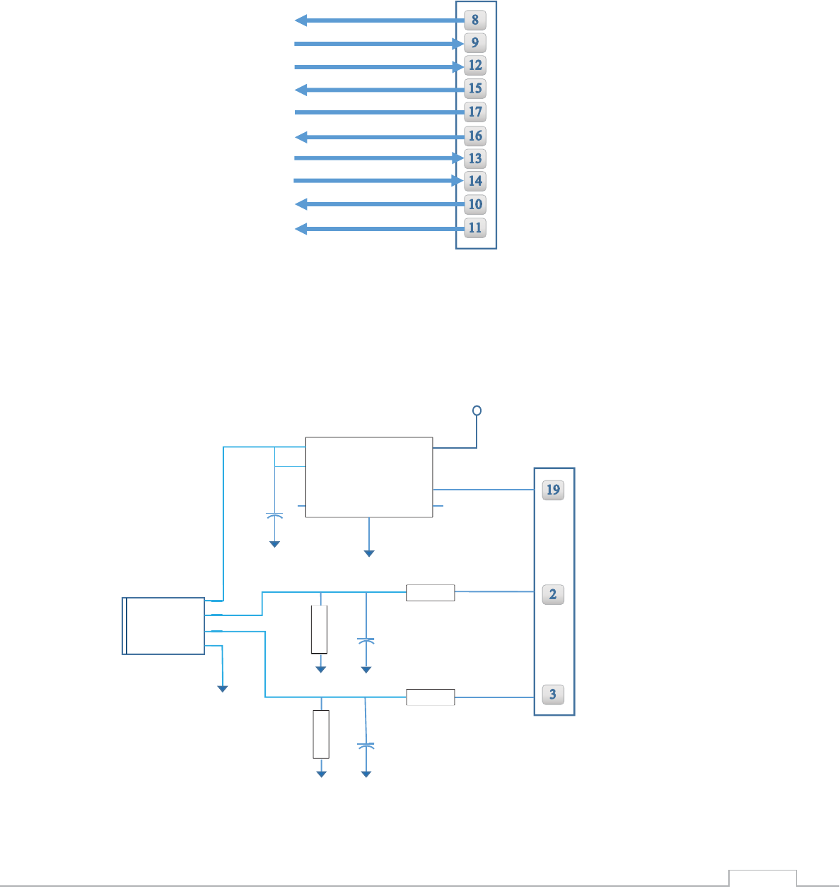
4) RMII Interface
5) USB 2.0 Host Interface
ETX EN
REF CLK
Nano SMT G2 Pins
CRSDV
ERXER
EMDIO
EMDC
ERX0
ERX1
ETX0
ETX1
Nano SMT G2 Pins
Vout Vin
Vout
EN
FLG GND EP
VDD
VBUS
USB A
GND
GND
47PF
47PF
100μF/6.3V
GND
GND
GND
GND
4
3
2
1
27Ω
27Ω
15KΩ
15KΩ
HDM
HDP
AP2171
Nano WiReach SMT G2 –Datasheet
18
7. Electrical Specifications
1) Absolute Maximum Ratings
Parameter
Rating
Voltage at any pin with respect to ground
-0.3V to +3.6V
Operating Temperature
-30⁰C to +85⁰C -22⁰F to +185⁰F
Storage Temperature
-40⁰C to +85⁰C -40⁰F to +185⁰F
2) DC Operating Characteristics
Parameter
Min
Typical
Max
Units
VDD
3.0
3.3
3.6
Volts
High Level Input
2.0
VDD I/O +0.3
Volts
Low Level Input
-0.3
0.8
Volts
High Level Output @2mA
VDD I/O -0.4
Volts
High Level Output @0mA
VDD I/O-0.2
Volts
Low Level Output @2mA
0.4
Volts
Low Level Output @0mA
0.2
Volts
Input Leakage Current
10
μA
Power Supply Current from VDD (Tx. Mode)
350
mA
Power Supply Current from VDD (Rcv. Mode)
130
mA
Power Supply Current from VDD (Power Save
Mode)
TBD
mA
Input Capacitance
5.3
pF
Radio Frequency Range
2.412
2.484
GHz
Nano WiReach SMT G2 –Datasheet
19
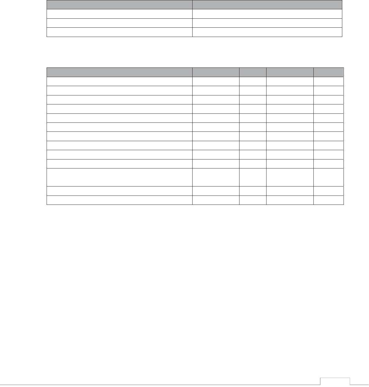
3) AC Operating Characteristics
4) Transmit Specification
Item
Condition
Min
Typ
Max
Unit
Transmit Power Levels
802.11b
15
17
19
dBm
802.11g
12
14
16
dBm
802.11n
10
12
14
dBm
Transmit Error vector
Magnitude
802.11b
11Mbps
-13
-11
dB
1Mbps
-13
-11
dB
802.11g
54Mbps
-30
-25
dB
6Mbps
-30
-22
dB
802.11n
HT20M@MCS0
-30
-22
dB
HT20M@MCS0
-30
-28
dB
5) Receive Specifications
Item
Condition
Min
Typ
Max
Unit
Receiver Minimum
Input Level Sensitivity
802.11b Data Rate = 11Mbps PER < 8%
-87
-83
dBm
802.11b Data Rate = 1Mbps PER < 8%
-94
-89
dBm
802.11g Data Rate = 54Mbps PER <10%
-73
-68
dBm
802.11g Data Rate = 6Mbps PER <10%
-86
-81
dBm
802.11n MCS0 PER <10%
-86
-81
dBm
802.11n MCS7 PER <10%
-70
-65
dBm
Nano WiReach SMT G2 –Datasheet
20
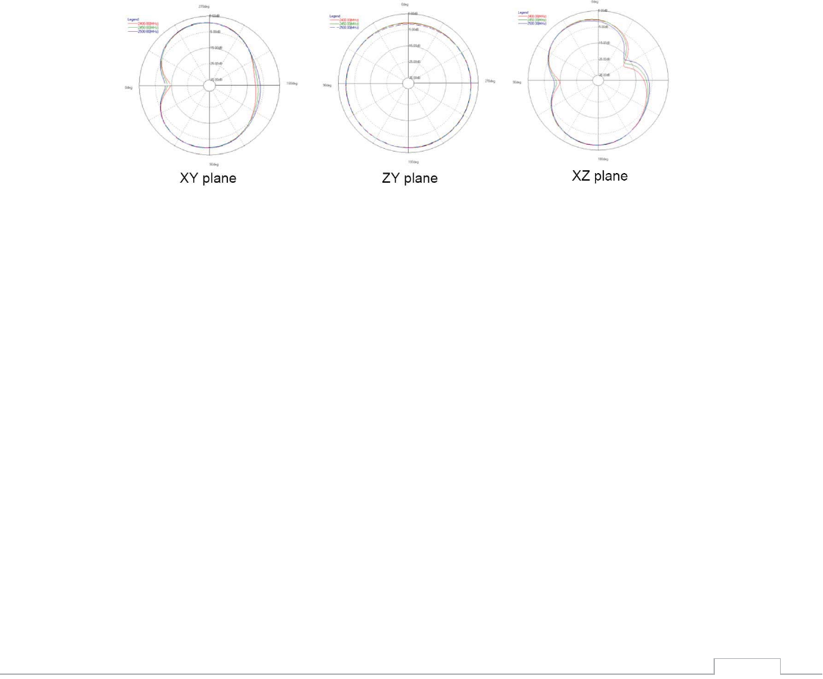
6) On Board Antenna
Designed for 2.4Ghz Operation
Peak Gain 2.1dBi
Average efficiency: 75%
Max Return Loss: -11dBi
Max VSWR: 1, 8:1
Antenna Patterns
Nano WiReach SMT G2 –Datasheet
21
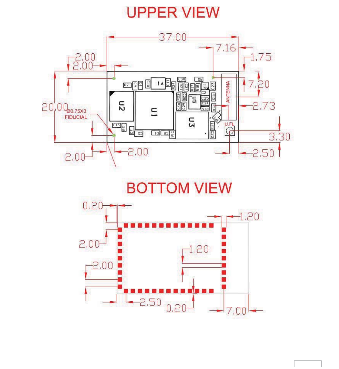
8. Mechanical Dimensions
All measurements are in millimeters +/- 0.2mm
Nano WiReach SMT G2 –Datasheet
22
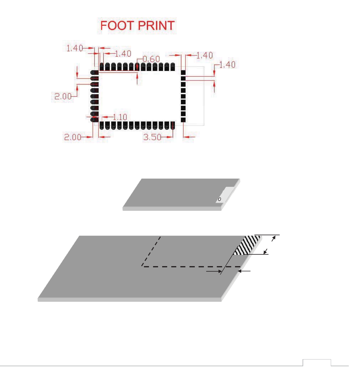
9. PCB Footprint Design Recommendation
1) Host PCB Footprint
2) Antenna Clearance Requirements
E1
Nano WiReach SMT G2
Host-PCB
18.01
8.24
Nano WiReach SMT G2 –Datasheet
23
10. Evaluation Board
The II-EVB-365-G2 evaluation board enables you to evaluate the Nano WiReach SMT G2 without
changing anything in your current development environment. Using a simple Windows-based
application on a PC, you can issue AT+i commands.
AT+i commands are used to configure parameter values into iChip’s flash memory and activate
Internet tasks such as email send, sockets, FTP sessions, configuration, and more.
A full description of AT+i commands can be found in the AT+i Programmer’s Manual on Connect
One’s website.
To help you evaluate the Nano WiReach SMT G2, Connect One supplies the iChip Config Utility. This
is a Windows-based application that contains intuitive dialog boxes to fully configure iChip CO2144.
It doesn’t require any knowledge of AT+i commands. It also contains local firmware update tools.
The iChip Config Utility allows you to perform specific Internet communication tasks such as sending
and receiving emails, activating iChip’s websites, entering SerialNET mode, and more. The latest
iChip Config Utility version and user manual can be found on Connect One’s website under the
Support section.
On board connectors allow a choice of Host interfaces:
x RS232 COM port
x SPI
x USB Device
11. Ordering Information
Part Number
Description
iW-SMG2SMT-EX
Nano WiReach SMT-G2 module, Surface Mounting, External Antenna
iW-SMG2SMT-OB
Nano WiReach SMT-G2 module, Surface Mounting, On Board Antenna

Nano WiReach SMT G2 –Datasheet
24
Appendix A - Internet Protocol Compliance
Nano WiReach SMT G2 complies with the Internet standards listed in the following table
RFC 768
User datagram protocol (UDP)
RFC 791
Internet protocol (IP)
RFC 792
ICMP – Internet control message protocol
RFC 793
Transmission control protocol (TCP)
RFC 821
Simple mail transfer protocol (SMTP)
RFC 822
Standard for the format of ARPA Internet text messages
RFC 826
Ethernet address resolution protocol (ARP)
RFC 959
File transfer protocol (FTP)
RFC 854
TELNET protocol specification
RFC 857
Telnet ECHO option
RFC 858
Telnet suppress go-ahead option
RFC 1034
Domain names (DNS) - concepts and facilities
RFC 1035
Domain names (DNS) - implementation and specification
RFC 1073
Telnet window size option
RFC 1091
Telnet terminal type option
RFC 1321
MD5 message digest algorithm
RFC 1939
Post office protocol - version 3 (POP3)
RFC 1957
Some observations on the implementations of the post office protocol (POP3)
RFC 2030
Simple network time protocol (SNTP)
RFC 2045
Multipurpose Internet mail extensions (MIME) part one: internet message body
format
RFC 2046
MIME part two: media types
RFC 2047
MIME part three: message header extensions for non-ASCII text
RFC 2048
MIME part four: registration procedures
RFC 2049
MIME part five: conformance criteria and examples
RFC 2068
Hypertext transfer protocol HTTP/1.1
RFC 2131
Dynamic host configuration protocol (DHCP)
RFC 2132
DHCP options (only relevant parts)
RFC 2228
FTP security extensions
RFC 2246
The TLS protocol version 1.0

Nano WiReach SMT G2 –Datasheet
25
Appendix B – AT+I Configuration Examples
Automatically connect to a specific Access Point:
AT+iFD (restore to factory defaults)
AT+iHIF=1 (set the serial interface to RS232)
AT+iBDRF=9 (fix baud rate to 115200 after power cycle)
AT+iRP20 (list visible networks)
AT+iWLSI=My_WiFi
AT+iWST0=4 (WPA2 security)
AT+iWPP0=<WPA2 passphrase>
AT+iAWS=1 (enable website upon reboot)
AT+iDOWN (reboot to apply settings)
Create an Access Point to allow connection from mobile devices:
AT+iFD (restore to factory defaults)
AT+iHIF=1 (set the serial interface to RS232)
AT+iBDRF=9 (fix baud rate to 115200 after power cycle)
AT+iWLSI=My_AP
AT+iDIP=10.0.0.1 (IP address)
AT+iDPSZ=8 (Enable internal DHCP server, up to 8 clients)
AT+iWST0=0 (open security)
AT+iAWS=1 (enable website upon reboot)
AT+iDOWN (reboot to apply settings)
LAN – WiFi switch mode - merges Ethernet station(s) with WiFi client(s) into one logical subnet
AT+iFD (restore to factory defaults)
AT+iHIF=1 (set the serial interface to RS232)
AT+iBDRF=9 (fix baud rate to 115200 after power cycle)
AT+iwlsi=SWITCH
AT+idpsz=8 (Enable internal DHCP server, up to 8 clients)
AT+iwst0=0 (open security)
AT+iltyp=4 (LAN type: WiFi+Ethernet)
AT+idip=192.168.0.1 (WiFi side IP address)
AT+isnet=255.255.255.0 (WiFi side subnet mask)

Nano WiReach SMT G2 –Datasheet
26
AT+iedip=192.168.0.100 (Ethernet side IP address)
AT+iesnt=255.255.255.0 (Ethernet side subnet mask)
AT+istap=1 (WiFi in Access Point mode)
AT+iswen=1 (Enable Switch Mode)
Nano WiReach SMT G2 –Datasheet
27
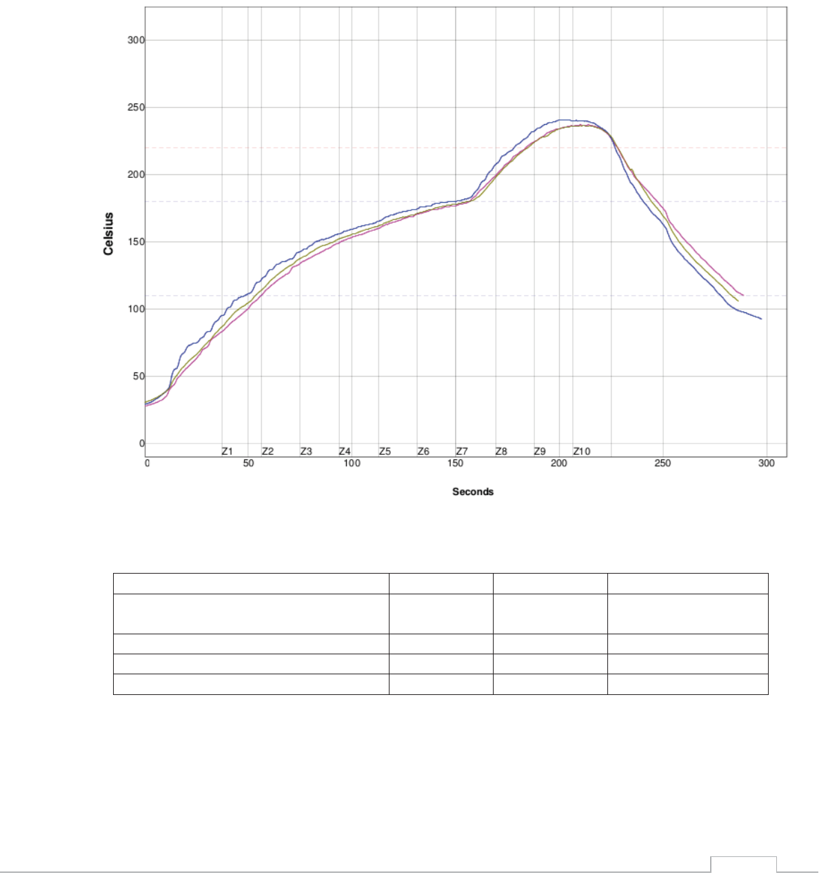
Appendix C – Soldering Profile
Solder Paste: LEAD FREE
Statistic Name
Low Limit
High Limit
Units
Max Rising Slope (Target=2.0)
(Calculate Slope over 20 Seconds)
0
4
Degrees/Second
Soak Time 110-180C
60
120
Seconds
Time Above Reflow - 220C
30
50
Second
Peak Temperature
235
250
Degrees Celsius