Connect Tech Blue Heat Net Sync Ctim 00044 Users Manual
CTIM-00044 to the manual 3db03e7d-9074-48fa-8796-23668f34815c
2015-02-05
: Connect-Tech Connect-Tech-Blue-Heat-Net-Sync-Ctim-00044-Users-Manual-530817 connect-tech-blue-heat-net-sync-ctim-00044-users-manual-530817 connect-tech pdf
Open the PDF directly: View PDF ![]() .
.
Page Count: 76
- Limited Lifetime Warranty
- Copyright Notice
- Trademark Acknowledgment
- Customer Support Overview
- Contact Information
- Certification Statements
- Table of Contents
- List of Figures
- List of Tables
- Introduction
- Blue Heat/Net Sync Installation Overview
- Hardware Installation
- Blue Heat/Net Sync Configuration
- Software Installation for Windows
- Firmware Upgrades
- Software Development
- Appendix
- Blue Heat/Net Sync Specifications
- Pinouts
- Rack Mount Option:
- Default Settings
- Common Configuration Setups
- How the Blue Heat/Net Sync Boots Up
- Serial Line Interface Tutorial
Blue Heat/Net Sync
User Manual
Ethernet-to-Serial Synchronous Communications
Connect Tech Inc.
42 Arrow Road
Guelph, Ontario
N1K 1S6
Tel: 519-836-1291
Toll: 800-426-8979 (North America only)
Fax: 519-836-4878
Email: sales@connecttech.com
support@connecttech.com
Web: www.connecttech.com
CTIM-00044 Revision 0.03 , July 8, 2010

Connect Tech Blue Heat/Net Sync User Manual
2 Revision 0.03
Limited Lifetime Warranty
Connect Tech Inc. provides a Lifetime Warranty for all Connect Tech Inc. products. Should this
product, in Connect Tech Inc.'s opinion, fail to be in good working order during the warranty
period, Connect Tech Inc. will, at its option, repair or replace this product at no charge, provided
that the product has not been subjected to abuse, misuse, accident, disaster or non Connect Tech
Inc. authorized modification or repair.
You may obtain warranty service by delivering this product to an authorized Connect Tech Inc.
business partner or to Connect Tech Inc. along with proof of purchase. Product returned to
Connect Tech Inc. must be pre-authorized by Connect Tech Inc. with an RMA (Return Material
Authorization) number marked on the outside of the package and sent prepaid, insured and
packaged for safe shipment. Connect Tech Inc. will return this product by prepaid shipment
service.
The Connect Tech Inc. lifetime warranty is defined as the serviceable life of the product. This is
defined as the period during which all components are available. Should the product prove to be
irreparable, Connect Tech Inc. reserves the right to substitute an equivalent product if available
or to retract lifetime warranty if no replacement is available.
The above warranty is the only warranty authorized by Connect Tech Inc. Under no
circumstances will Connect Tech Inc. be liable in any way for any damages, including any lost
profits, lost savings or other incidental or consequential damages arising out of the use of, or
inability to use, such product.
Copyright Notice
The information contained in this document is subject to change without notice. Connect Tech
Inc. shall not be liable for errors contained herein or for incidental consequential damages in
connection with the furnishing, performance, or use of this material. This document contains
proprietary information that is protected by copyright. All rights are reserved. No part of this
document may be photocopied, reproduced, or translated to another language without the prior
written consent of Connect Tech, Inc.
Copyright © 2010 by Connect Tech Inc.
Trademark Acknowledgment
Connect Tech Inc. acknowledges all trademarks, registered trademarks and/or copyrights
referred to in this document as the property of their respective owners.
Not listing all possible trademarks or copyright acknowledgments does not constitute a lack of
acknowledgment to the rightful owners of the trademarks and copyrights mentioned in this
document.

Connect Tech Blue Heat/Net Sync User Manual
Revision 0.03 3
Customer Support Overview
If you experience difficulties after reading the manual and/or using the product, contact the
Connect Tech reseller from which you purchased the product. In most cases the reseller can help
you with product installation and difficulties.
In the event that the reseller is unable to resolve your problem, our highly qualified support staff
can assist you. Our support section is available 24 hours a day, seven days a week on our
website at:
www.connecttech.com/sub/support/support.asp. See the contact information section below for
more information on how to contact us directly. Our technical support is always free.
Contact Information
We offer three ways for you to contact us:
Telephone/Facsimile
Technical Support representatives are ready to answer your call Monday through Friday, from
8:30 a.m. to 5:00 p.m. Eastern Standard Time. Our numbers for calls are:
Telephone: 800-426-8979 (North America only)
Telephone: 519-836-1291 (Live assistance available 8:30 a.m. to 5:00 p.m. EST, Monday to
Friday)
Facsimile: 519-836-4878 (online 24 hours)
Email/Internet
You may contact us through the Internet. Our email and URL addresses are:
sales@connecttech.com
support@connecttech.com
www.connecttech.com
Mail/Courier
You may contact us by letter and our mailing address for correspondence is:
Connect Tech Inc.
Technical Support
42 Arrow Road
Guelph, Ontario
Canada N1K 1S6
Note:
Please go to the Download Zone or the Knowledge Database in the
Support Center on the Connect Tech website for product
manuals, installation guides, device driver software and
technical tips.
Submit your technical support questions to our customer support engineers via the Support
Center on the Connect Tech website.

Connect Tech Blue Heat/Net Sync User Manual
4 Revision 0.03
Certification Statements
Preliminary: Testing is still pending.
Class A Computing Device
Connect Tech Inc. declares that the product(s) covered by the contents of this manual have been
tested and found compliant with the below listed standards as required by the Electromagnetic
Compatibility (EMC) Directive for General Immunity Compliance.
EN 55022 Conducted and Radiated emissions
CISPR 22 Class A
EN 55024 Immunity to Disturbances
EN 61000-4-2
EN 61000-4-4
EN 61000-4-6
EN 61000-3-2 Exempt
EN 61000-4-3
EN 61000-4-5
EN 61000-4-11
EN 61000-3-3 Pass
The above satisfy the requirements of:
Preliminary: Testing is still pending.
USA:
FCC – CFR47, Part 15, part 2
Canada:
ICES-003
Europe
EMC Directive
Japan:
VCCI
Australia/New Zealand:
AS/NZS

Connect Tech Blue Heat/Net Sync User Manual
Revision 0.03 5
Table of Contents
Limited Lifetime Warranty ................................................................................................................... 2
Copyright Notice ................................................................................................................................ 2
Trademark Acknowledgment ................................................................................................................ 2
Customer Support Overview ................................................................................................................ 3
Contact Information............................................................................................................................ 3
Certification Statements ...................................................................................................................... 4
Table of Contents ............................................................................................................................... 5
List of Figures .................................................................................................................................... 7
List of Tables ..................................................................................................................................... 8
Introduction ....................................................................................................................................... 9
Features .................................................................................................................. 9
Understanding Virtual COM Ports ........................................................................... 10
Blue Heat/Net Sync Installation Overview ........................................................................................... 10
Hardware Installation ....................................................................................................................... 11
Connecting the Blue Heat/Net Sync to Your Network: ................................................. 11
Ethernet LEDs ............................................................................................... 11
Serial Port LEDs ............................................................................................ 12
Connecting Serial Devices ....................................................................................... 12
V.28 Connections: .......................................................................................... 12
Basic Async (V.28) RS-232 Null Modem Connection ................................. 12
Basic Sync (V.28) RS-232 Connection (Provides Clock) ............................ 12
Basic Sync (V.28) RS-232 Connection (Receives Clock) ............................. 12
RS-422/V.11 Connections ................................................................................ 13
Blue Heat/Net Synchronous Clocking ........................................................................ 13
Loopback Connectors .............................................................................................. 14
Connecting Power .................................................................................................. 15
DC Power Connector ............................................................................. 15
Phoenix Locking Screw Terminal Connector ............................................ 15
Activating the Special Operations Mode and Default Settings ...................................... 17
Using the Reset Button to Activate the Special Operations Mode ......................... 17
Selecting a Special Operation .......................................................................... 17
Power On Diagnostics: ........................................................................................... 18
LED Error Codes ........................................................................................... 18
SCM Cabling requirements ...................................................................................... 21
SCM: Serial Configuration Manager ................................................................ 21
Setting a Static or Dynamic IP Address ..................................................................... 21
Set the IP Address Using the Web Configuration Manager ................................. 22
Set the IP Address Using the Serial Configuration Manager ............................... 22
Blue Heat/Net Sync Configuration ...................................................................................................... 23
CDS (Configuration Data Space) ............................................................................. 24
Description .................................................................................................... 24
Access to CDS Parameters .............................................................................. 24
SCM (Serial Configuration Manager) ....................................................................... 25
Description .................................................................................................... 25
Getting Access to the SCM .............................................................................. 25
SCM Command Reference ............................................................................... 25
Brief Command List ............................................................................... 25
Command Details .................................................................................. 26
boot ............................................................................................. 26
cfg ............................................................................................... 26
exit .............................................................................................. 27
help ............................................................................................. 27

Connect Tech Blue Heat/Net Sync User Manual
6 Revision 0.03
info .............................................................................................. 27
net ............................................................................................... 27
save ............................................................................................. 29
update .......................................................................................... 29
WCM (Web Configuration Manager) ........................................................................ 31
Signing In to the Web Configuration Manager .................................................. 31
Configure Advanced Serial Settings ......................................................... 33
Configure Blue Heat/Net Sync Settings .................................................... 33
Configure Firmware .............................................................................. 35
Restore Defaults .................................................................................... 35
Saving To Flash..................................................................................... 36
Monitoring Your Blue Heat/Net ....................................................................... 37
Monitor Serial Port Traffic ..................................................................... 37
Monitor Network Traffic ......................................................................... 38
Monitor TCP/IP Statistics ....................................................................... 38
My Blue Heat/Net Sync........................................................................... 38
Software Installation for Windows ...................................................................................................... 40
Installing the Blue Heat/Net Sync Configuration Manager .......................................... 40
Running the Configuration Manager ......................................................................... 44
Device Installation .................................................................................................. 44
Configure Default Blue Heat/Net Sync .............................................................. 45
Add New Blue Heat/Net Sync ........................................................................... 45
Auto Discover Blue Heat/Net Sync ................................................................... 46
Firmware Upgrades.......................................................................................................................... 47
Upgrade using WCM (Web Configuration Manager) .................................................. 47
Upgrade using SCM (Serial Configuration Manager) ................................................. 47
Software Development ...................................................................................................................... 48
Memory Map of IUSC and PLD Functions ........................................................ 50
ColdFire (5272) Bus: ............................................................................. 50
IUSC Access: ........................................................................................ 50
PLD Resource Access: ........................................................................... 51
PLD Memory Map Table................................................................................. 51
Port Settings, Clock Setup and General Settings......................................................... 59
IUSC Clocking Logic: ............................................................................................. 61
Appendix ......................................................................................................................................... 62
Blue Heat/Net Sync Specifications ............................................................................ 62
Operating Environment .................................................................................. 62
Communications ............................................................................................ 62
ESD Protection .............................................................................................. 62
Power ........................................................................................................... 62
Connectors .................................................................................................... 62
Dimensions .................................................................................................... 62
Cable and Power Supply Options ..................................................................... 62
Protocol Descriptions ..................................................................................... 63
Pinouts .................................................................................................................. 64
DB-25 Female Pinouts .................................................................................... 64
DB-9 Female Pinouts ..................................................................................... 65
Multi-drop Communications Using V.11 / RS422/RS485 Line Modes ................... 66
Rack Mount Option: ................................................................................................ 66
Default Settings ...................................................................................................... 67
Network Settings ............................................................................................ 67
Boot Settings .................................................................................................. 67
SCM Operation Settings .................................................................................. 67
Common Configuration Setups ................................................................................. 68
Static IP Setup ............................................................................................... 68
Using SCM ........................................................................................... 68
Using WCM .......................................................................................... 68

Connect Tech Blue Heat/Net Sync User Manual
Revision 0.03 7
DHCP Setup .................................................................................................. 69
Using SCM ........................................................................................... 69
How the Blue Heat/Net Sync Boots Up ...................................................................... 69
Bootup Sequence ............................................................................................ 70
Flowchart of Special Operations Mode using the reset button ............................. 71
Asynchronous Communications Tutorial ........................................................... 71
Serial Line Interface Tutorial ................................................................................... 72
RS-232 Line Interface: .................................................................................... 72
Differential Line Interfaces: ............................................................................ 72
RS485/RS422/V.11 Details .............................................................................. 72
Basic 4-Wire, Full Duplex Communications: ............................................ 73
Multi-drop 4-Wire, Full Duplex Communications: .................................... 74
Basic - Wire, Half Duplex Multi-drop Connection: .................................... 74
Bus Contention on Differential Multi-drop Networks: ........................................ 75
Termination Resistors in Differential Networks ................................................. 76
Termination Resistors in Differential Networks:........................................ 76
List of Figures
Figure 1: LED Locations on Blue Heat/Net Sync.......................................................................... 11
Figure 2: Basic V.28 Asynchronous Connections ......................................................................... 12
Figure 3: Basic V.28 Synchronous Connections ........................................................................... 12
Figure 4: Basic V.28 Synchronous Connections ........................................................................... 12
Figure 5: Basic RS-422/V.11 Asynchronous Connections ............................................................ 13
Figure 6: Basic RS422/V.11 Synchronous Connections ................................................................ 13
Figure 7: Recommended Pinouts for V.28 (RS-232) Loopback Connector ................................... 14
Figure 8: Recommended Pinouts for a V.11 (RS422) Loopback Connector ................................. 14
Figure 9: DC Power Connector Illustration ................................................................................. 15
Figure 10: Phoenix Locking Screw Terminal Power Connector Illustration ................................ 15
Figure 11: LED Error Code Example ........................................................................................... 18
Figure 12: Blue Heat/Net Sync Serial Cable Connection Diagram .............................................. 21
Figure 13: Web Configuration Manager Sign In .......................................................................... 31
Figure 14: Blue Heat/Net Sync Settings ........................................................................................ 32
Figure 15: Configuring Blue Heat/Net Sync Settings .................................................................... 35
Figure 16: Firmware Upgrades/Downloads ................................................................................. 35
Figure 17: Restore Default Settings .............................................................................................. 36
Figure 18: Saving To Flash ........................................................................................................... 37
Figure 19: Monitoring Serial Port Activity ................................................................................... 37
Figure 20: Monitoring Network Traffic ........................................................................................ 38
Figure 21: Monitoring TCP/IP Statistics ...................................................................................... 38
Figure 22: My Blue Heat/Net Sync Hardware Details .................................................................. 39
Figure 23: My Blue Heat/Net Sync Software Details .................................................................... 39
Figure 24: Blue Heat/Net Sync Driver/Software Installation CD ................................................. 40
Figure 25: Blue Heat/Net Sync Software Installation Screen ....................................................... 41
Figure 26: My Blue Heat/Net Sync Places Screen ........................................................................ 44
Figure 27: Add or Auto Discover Blue Heat/Net Sync Menu Screen ............................................ 45
Figure 28: Add Blue Heat/Net Sync Screen .................................................................................. 45
Figure 29: Auto Discover Blue Heat/Net Sync Screen .................................................................. 46
Figure 46: Bootup Sequence ......................................................................................................... 70
Figure 47: Bootup Sequence via Reset Button .............................................................................. 71
Figure 48: Typical Asynchronous Date Frame ............................................................................. 72

Connect Tech Blue Heat/Net Sync User Manual
8 Revision 0.03
List of Tables
Table 1: BlueHeat/Net Sync Power Connections and Current Specifications .............................. 16
Table 2: Connector Properties ...................................................................................................... 16
Table 3: Available Special Operations .......................................................................................... 18
Table 4: LED Error Codes for Blue Heat/Net Sync ...................................................................... 19
Table 5: Chip Selects .................................................................................................................... 48
Table 6: Interrupts ......................................................................................................................... 49
Table 7: ColdFire MCF5272 GPIO .............................................................................................. 49
Table 8: Base Address Map ........................................................................................................... 49
Table 9: DB-25 Female Pinouts .................................................................................................... 64
Table 10: DB-9 Female Pinouts .................................................................................................... 65

Connect Tech Blue Heat/Net Sync User Manual
Revision 0.03 9
Introduction
Connect Tech‟s Blue Heat/Net Sync allows remote access to synchronous/asynchronous serial
devices via an Ethernet LAN or the Internet. Blue Heat/Net Sync network-enables serial
communication devices that are designed to be connected to serial ports so that the devices no
longer need to be tied to a single computer.
The Blue Heat/Net Sync hardware is simple to install as it involves little more than plugging the
unit into the appropriate locations and performing the configuration steps outlined in this
manual.
Driver setup is made easy by Blue Heat/Net Sync‟s auto-detection feature. The software does the
work of locating the units, while the Configuration Manager leads you through the rest of the
installation.
Blue Heat/Net Sync‟s firmware is easily configured with a choice of methods: web browser,
Telnet, or direct serial connection with a terminal and/or terminal software. Once the Blue
Heat/Net Sync has been configured to your specifications, you will be able to remotely access
your devices immediately.
Features
● Four software selectable synchronous or asynchronous serial ports
● Software switchable; V.28, V.10, V.11, V.35, EIA-530, X.21 line modes
● Software switchable line modes and termination
● Supports NRZ, NRZB, NRZI-Mark, NRZI-Space, B-Phase-Space, B-Phase-Manchester,
Differential Bi-Phase encoding
● Transmission rates up to 9.216 Mbps (synchronous), 230.4 Kbps (asynchronous). 10 Mbps
communications possible with external clock.
● Bipolar clock input accepts sine/square wave signals up to 20 MHz +/- 10V.
● Includes synchronous protocols; SDLC, HDLC, MonoSync, BiSync, Transparent BiSync
● Software selectable internal and external clocking modes. External clocking is provided on
TXC and RXC pins
● Supports IP, TCP, UDP, ARP, RARP, TFTP, DHCP, BOOTP, HTTP, Telnet and DNS
● Use of TCP/IP means communications can be routed to support WANs, as well as LANs.
The Blue Heat/Net Sync does not need to be located at the same site as the controlling
computer
● Raw TCP server (HDLC and External Sync Line Modes only)
● Several levels of security are built into the Blue Heat/Net Sync that can limit connections
and help to ensure the privacy of data flow
● Memory: 8 MB flash, 16 MB SDRAM
● Includes an auto-MDIX 10Base-T, 100Base-TX LAN interface
● Network boot or booting from built-in flash memory
● Firmware upgrades are downloadable
● Customizable uClinux embedded operating system running on a ColdFire embedded
processor.
● Configuration can be done via Web Browser, Telnet or direct serial connection
● Front mounted diagnostic LEDs
● 5-28 VDC power input using either DC barrel or Phoenix screw terminal connector
Optional 5VDC power supply available
● 1U rack mount kit available

Connect Tech Blue Heat/Net Sync User Manual
10 Revision 0.03
Understanding Virtual COM Ports
In a typical serial port setup, the application communicates directly with the connected serial
port hardware.
Virtual COM ports differ in that the application communicates with a network protocol layer that
transfers the necessary information to and from the remote serial ports. The virtual ports appear
as standard serial ports to the application, but in reality the data is translated into a series of
Ethernet messages between the Blue Heat/Net Sync unit and the host computer. The serial port is
not physically connected to the host computer, but this is transparent to the application trying to
access it.
There are several advantages to using virtual COM ports, which include:
Distance – The serial ports can be a great distance away from the host computer. They are
not limited by the standard electrical characteristics of the RS-232 or RS-422 interface
because the primary data transfer is being done via Ethernet. Depending on the set up, these
serial ports can be at a different location and the Internet can act as the carrier of the serial
port traffic.
Speed – Short RS-232/422 cable lengths can be used with the primary distance relying on
the network connection. The capacitance of long lengths of serial cable does not limit data
speeds in these cases.
Cabling – Cost effective Ethernet cabling can be used for the transfer of information to the
Blue Heat/Net Sync and often this is part of the existing networking infrastructure.
Connecting serial ports in a remote location can be as easy as plugging in a Blue Heat/Net
Sync to the Ethernet network. This provides a simple, clean cabling arrangement.
Port Sharing – In some applications it is desirable to have a serial resource that is accessed
and shared by more than one host computer. Connect Tech‟s virtual serial port technology
allows this to be done easily.
Routing – Different ports on a Blue Heat/Net Sync can be connected to multiple host
computers.
Monitoring – Because the virtual serial ports are on the network, they can easily be
monitored to ensure everything is operating correctly.
Blue Heat/Net Sync Installation Overview
There are three main stages in the installation process for your Blue Heat/Net Sync.
1. Hardware Installation
This involves the physical connection of the Blue Heat/Net Sync hardware to your
network, and addresses issues such as cabling and power requirements.
2. Blue Heat/Net Sync Configuration
The first step in the configuration process is to set the IP Address. Then use one of three
available methods to configure the Blue Heat/Net Sync firmware settings for your
application. This can be done through the SCM (Serial Configuration Manager) or the
WCM (Web Configuration Manager), depending on circumstances and personal
preference.
3. Software Installation for Windows
This step installs and configures the Blue Heat/Net Sync drivers and ports for your host
Operating System and allows you to set parameters specific to your serial requirements.
This is done via the Blue Heat/Net Sync Configuration Manager.
NOTE: Software support for Windows and Linux is still in
development
Connect Tech Blue Heat/Net Sync User Manual
Revision 0.03 11
Hardware Installation
Connecting the Blue Heat/Net Sync to Your Network:
Before you begin, take a minute to ensure that your package includes the required components
for your Blue Heat/Net Sync:
• One Blue Heat/Net Sync unit
• One power supply
• One CD containing software and documentation
• One Phoenix contact screw terminal plug PN: 1847055
• One RJ-45 cable (optional)
If any of these components is missing, contact Connect Tech or your reseller.
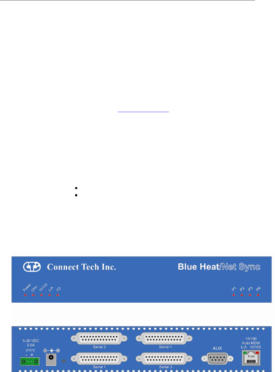
Ethernet LEDs
The front panel of the Blue Heat/Net Sync features Ethernet and serial port LEDs to monitor
activity.
Power: When this LED is on, the Blue Heat/Net Sync is receiving power.
CPU: Once the uClinux firmware is booted and running correctly, this LED lights up.
10/100: This LED represents the line rate at which the Blue Heat/Net Sync is connected
to your network.
LED on = a 100 megabit connection.
LED off = a 10 megabit connection.
(The Blue Heat/Net Sync automatically detects the line rate of your network).
L/A: This light illuminates when the connection to your network or computer is
achieved.
A blinking light indicates that Transmit (Tx) or Receive (Rx) activity is detected
on the Ethernet cable.
FD: Indicates that your network is running in full duplex or half duplex mode:
ON = full duplex, OFF = half duplex
Figure 1: LED Locations on Blue Heat/Net Sync

Connect Tech Blue Heat/Net Sync User Manual
12 Revision 0.03
Serial Port LEDs
The serial ports LEDs indicate serial activity for each port.
• A flashing LED indicates that the port in question is receiving or transmitting data.
Connecting Serial Devices
V.28 Connections:
V.28 has signaling levels the same EIA RS232.
Basic Async (V.28) RS-232 Null Modem Connection
This is the typical way to connect a Blue Heat/Net Sync to another serial device.
Figure 2: Basic V.28 Asynchronous Connections
Basic Sync (V.28) RS-232 Connection (Provides Clock)
Figure 3: Basic V.28 Synchronous Connections
Basic Sync (V.28) RS-232 Connection (Receives Clock)
Figure 4: Basic V.28 Synchronous Connections
NOTE: The Blue Heat/Net Sync clock signals are bidirectional.
See Blue Heat/Net Sync Clocking for more details.
2 - TX
3 - RX
15 - T/RXC
7 - SR
RX
TX
RXC
SR
Blue Heat/Net Sync
RS-232 Device
2 - TX
3 - RX
17 - T/RXC
7 - SR
RX
TX
RXC
SR
Blue Heat/Net Sync
RS-232 Device
2 - TX
3 - RX
7 - SR
RX
TX
SR
Blue Heat/Net Sync
RS-232 Device

Connect Tech Blue Heat/Net Sync User Manual
Revision 0.03 13
RS-422/V.11 Connections
The following are basic connections that can be accomplished when the I/O levels are in V.11 (RS-
422) mode. V.11 mode signaling can be enabled with EIA-530, RS-449 or X.21 modes on your Blue
Heat/Net Sync.
Figure 5: Basic RS-422/V.11 Asynchronous Connections
Figure 6: Basic RS422/V.11 Synchronous Connections
NOTE: Blue Heat/Net Sync clock signals are bidirectional. The
Blue Heat/Net Sync can either source or receive a clock. See Blue
Heat/Net Sync Clocking for more details.
Blue Heat/Net Synchronous Clocking
The clocking circuits on the Blue Heat/Net Sync are very flexible. The Blue Heat/Net Sync DB-25 clock
pins are bi-directional. This means that the TXC or RXC pins can be inputs receiving a clock or outputs
driving a clock. Functionally the two pins are equal. For example, the following clocking combinations are
possible:
RXC as clock input and TXC as clock input.
RXC as clock output and TXC as clock output.
RXC as clock input and TXC as clock output.
RXC as clock output and TXC as clock input.
The Blue Heat/Net Sync receivers and transmitters can be clocked independently from any combination of
the above or from internal clock sources.
Clocking is also available from the EXT_REF_CLK input pin on the DB-9 female.
2 - TX-
14 - TX+
16 - RX+
3 - RX-
9 - R/TXC+
17 - R/TXC-
7 - SR
RX-
RX+
TX+
TX-
RXC
RXC
SR
Blue Heat/Net Sync
RS-422/V.11 Device
2 - TX-
14 - TX+
16 - RX+
3 - RX-
7 - SR
RX-
RX+
TX+
TX-
SR
Blue Heat/Net Sync
RS-422/V.11 Device

Connect Tech Blue Heat/Net Sync User Manual
14 Revision 0.03
Loopback Connectors
Loopback connectors are useful for performing diagnostics. The following figure illustrates the
recommended pinouts for creating loopback connectors for Blue Heat/Net Sync.
Figure 7: Recommended Pinouts for V.28 (RS-232) Loopback Connector
Figure 8: Recommended Pinouts for a V.11 (RS422) Loopback Connector
NOTES:
1. For an asynchronous loopback, omit the TXC and RXC pin.
2. When using clock signals, one signal must be configured as an
input, while the other must be configured as an output.
3. When using a DB-25 female loopback connector, solder cup
DB-25 connectors and 24 AWG solid core wire, such as wire
from a CAT5 cable is recommended.
2 - TX-
14 - TX+
16 - RX+
3 - RX-
9 - RXC+
17 - RXC-
11 - TXC+
12 - TXC-
7 - SR
DB-25 Male
2 - TX
3 - RX
4 - RTS
5 - CTS
6 -DSR
8 - DCD
20 - DTR
22 - RI
15 - TXC
17 - RXC
DB-25 Male
Connect Tech Blue Heat/Net Sync User Manual
Revision 0.03 15
Connecting Power
The Blue Heat/Net Sync uses either a standard DC power jack or a Phoenix locking screw
terminal connector for power input. The Blue Heat/Net Sync can be safely connected or
disconnected at any time. The standard power supply requirements are as follows:
Model BMG006
5V (2.5A) power input using a DC barrel or Phoenix screw terminal connector. Rev A
models.
5V (2.5A) – 28 V DC (450mA) power input using a DC barrel or Phoenix screw terminal
connector. Rev B or greater models only.
DC Power Connector
Figure 9: DC Power Connector Illustration
NOTE: The center is positive, outside is ground (0V).
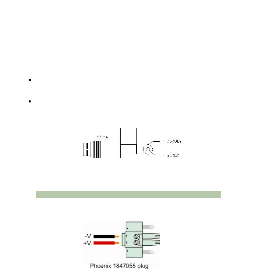
Phoenix Locking Screw Terminal Connector
Figure 10: Phoenix Locking Screw Terminal Power Connector Illustration

Connect Tech Blue Heat/Net Sync User Manual
16 Revision 0.03
Table 1: BlueHeat/Net Sync Power Connections and Current Specifications
BlueHeat/Net
Description
Connector plug
type
Connector
Polarity
Voltage
Current
4 Port DB25
Synchronous /
Asynchronous
models (Rev A)
Centre Positive*
5VDC
875mA
Left Positive*
5-28VDC
@5V=2500mA
@28V=450mA
4 Port DB25
Synchronous /
Asynchronous
models (Rev B)
Centre Positive*
5-28VDC
@5V=2500mA
@28V=450mA
Left Positive*
5-28VDC
@5V=2500mA
@28V=450mA
*Note: The power input is protected by a series diode to prevent damage in the case of a reverse polarity
connection.
Table 2: Connector Properties
Type
Details
Part Number
Typical Wire
Gauge
Standard DC Barrel
2.1mmID / 5.5mmOD
Digi-Key: CP3-1000-ND, or
equivalent
18-24 AWG
Stranded
Locking Screw Terminal,
3.3mm pitch
MC Series
Phoenix PN: 1847055, or
equivalent
16-28 AWG
Stranded
Screw Terminal,
3.5mm pitch
MC Series
Phoenix PN: 1840366, or
equivalent
16-28 AWG
Stranded

Connect Tech Blue Heat/Net Sync User Manual
Revision 0.03 17
Activating the Special Operations Mode and Default Settings
Blue Heat/Net Sync includes a push button on the rear of the unit beside the DC power
connector. This push button can be used to perform special operations such as resetting the unit
to its default settings or forcing port scanning in situations where the SCM is not accessible.
Using the Reset Button to Activate the Special Operations Mode
To activate the Special Operations Mode, hold the reset button while the unit is powering up.
Hold the button until all the port LEDs blink rapidly and then release the reset button. The port
LEDs will continue to flash rapidly after the reset button is released to indicate the Special
Operations Mode is active.
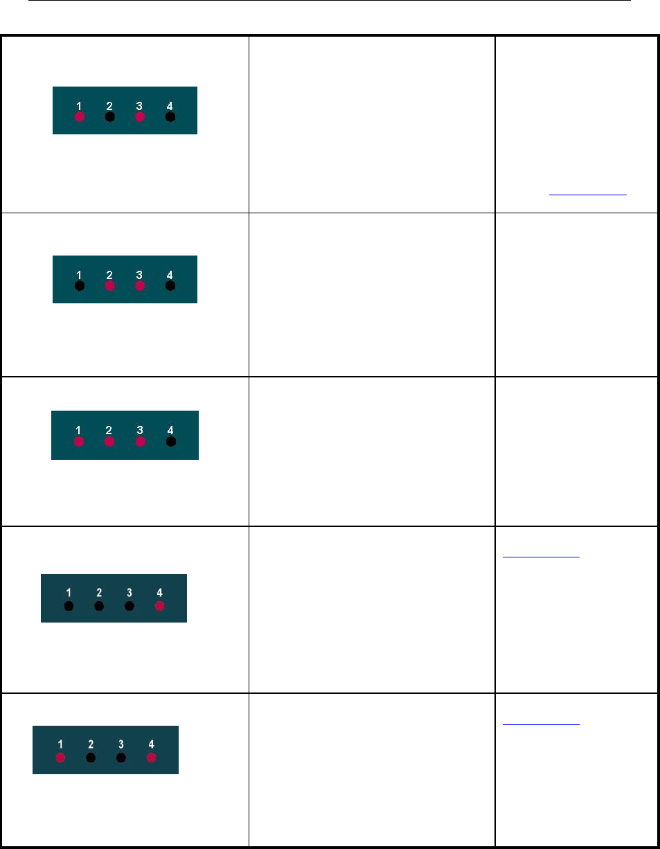
Selecting a Special Operation
Once the Special Operations Mode has been activated, four operation options are available:
1. Abandon the Special Operations Mode
To abandon the Special Operations Mode without selecting a special operation, press
and hold the reset button for at least four seconds. While the button is pressed, the
rapid flashing of the port LEDs will stop. After four seconds, the rapid flashing will
resume and the reset button can be released. After the release of the reset button, the
port LEDs will turn off, indicating that the Special Operations Mode has terminated.
2. Cancel a Special Operation
If you need to cancel a special operation after it has been selected, repeatedly press the
reset button until all the port LEDs begin to flash rapidly. Then abandon the Special
Operations Mode by pressing the reset button for four seconds, as explained above.
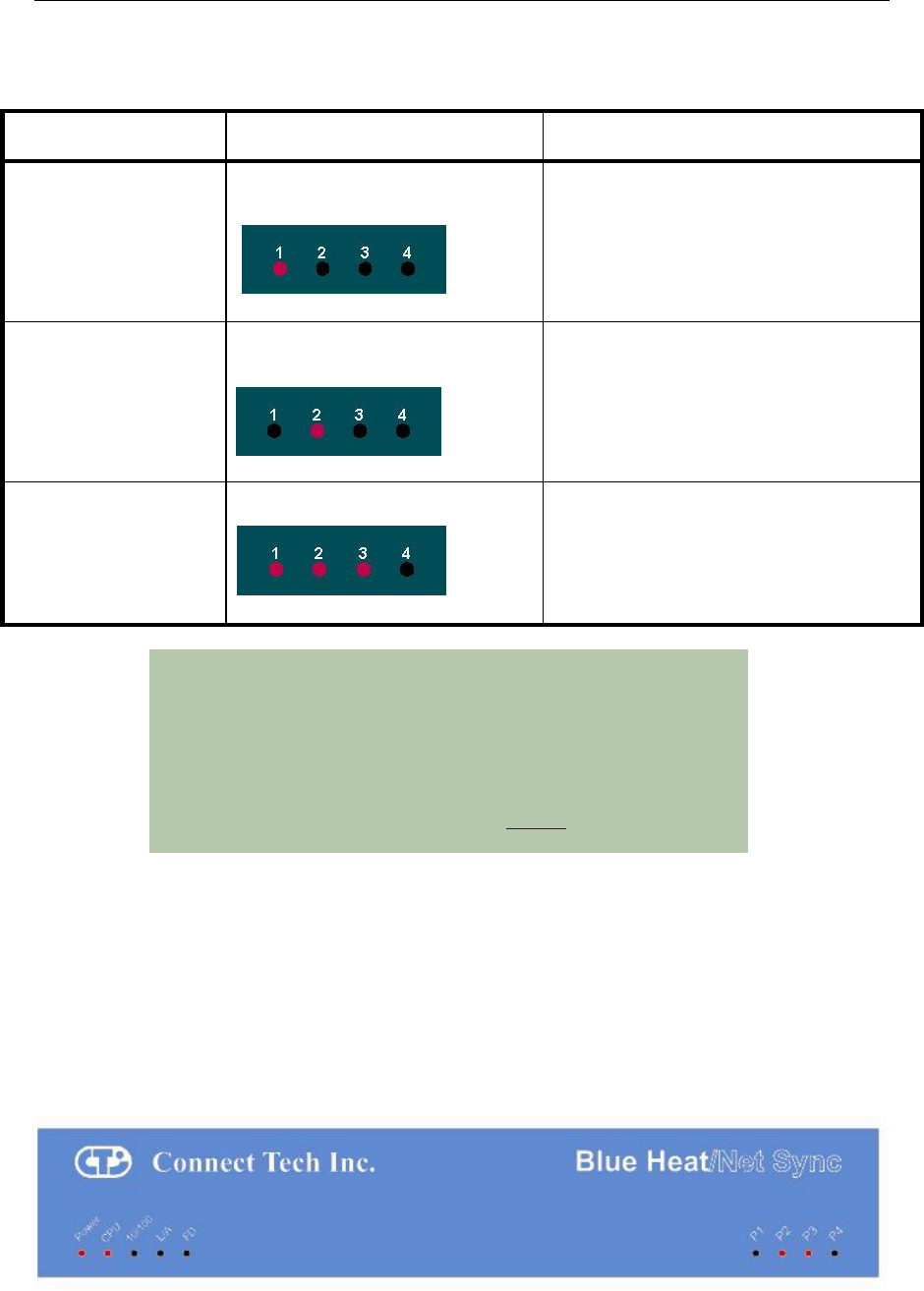
3. Select a Special Operation
Operations are selected by repeated short presses of the reset button. Each time the
reset button is pressed it is counted and represented on the port LEDs as a binary
number with the port 1 LED as the least significant bit (see Table 1). Choose the
operation which you want to perform. If you miss the selection that you want, keep
pressing the button. The count starts over again once it reaches 7 (1111 binary).
4. Activate a Special Operation
To activate a selection, press and hold the reset button for at least four seconds. During
this time the rapid flashing of the port LEDs will stop. Once the rapid flashing resumes
you can release the reset button. The port LEDs will turn off indicating that the Special
Operations Mode has been activated.
Connect Tech Blue Heat/Net Sync User Manual
18 Revision 0.03
Table 3: Available Special Operations
Special Operation
Number of presses (and binary
representation)
Usage
Force port scanning to
first two ports
(Scanning runs until
current scanning delay
setting times out. Default
is 30 seconds).
ONE press
This forces the first two ports to RS-232
mode, causing the SCM to scan these ports
and thereby allowing access to the SCM (see
note below).
Force port scanning to all
ports.
(Scanning runs until the
SCM is entered or until
the unit is powered
down. There is no time
out).
TWO presses
This forces all ports to RS-232 mode,
therefore all ports are scanned for SCM use.
The Blue Heat/Net Sync will behave in the
same manner as an RS-232 only model (see
note below).
Restore factory default
settings
SEVEN presses
This restores the factory default settings for
ALL configuration parameters.
NOTE: Why would I need to force port scanning?
Some line interface settings are inappropriate for SCM use.
During boot up, the SCM scans only those ports set for RS-232
mode. If all of the ports are configured for another mode, (1/2
Duplex or Multi-drop) SCM port scanning is bypassed, and the
SCM application cannot be accessed. Use of either of the “Force
Port Scanning” operations outlined in Table 1 will force port
scanning to occur so the SCM application can be accessed.
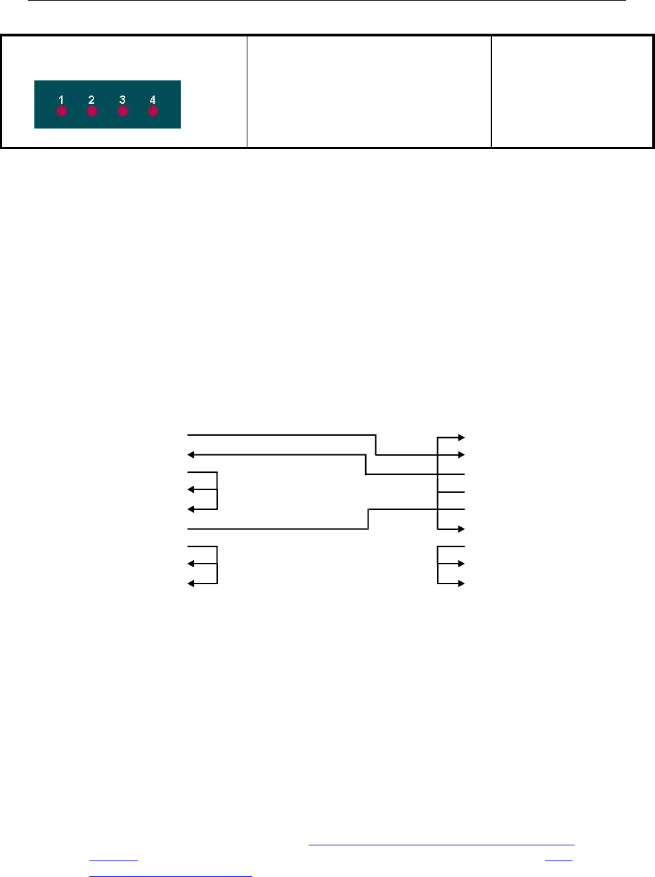
Power On Diagnostics:
LED Error Codes
If an error is detected during the bootup process, an error condition and code are displayed on
the LEDs on the face of the Blue Heat/Net Sync.
• The error condition is signaled by a rapidly flashing CPU LED (about 10 to 20 per
second).
• The error code is displayed on Port LEDs 1 to 4 as a binary number.
Figure 11: LED Error Code Example

Connect Tech Blue Heat/Net Sync User Manual
Revision 0.03 19
In the above example, a rapidly flashing CPU LED during the boot up process signifies the Blue
Heat/Net Sync has experienced an error. Port LEDs 1 through 4 signify which error has
occurred. In this case, LED 2 and 3 are on, so the error code is 6. The chart below defines the
error details for each error code.
Table 4: LED Error Codes for Blue Heat/Net Sync
Error Code and Event
Details
Suggested Corrective
Action
1. Loader code in flash is erased.
The regions of flash memory which hold
the loader code are both erased. (There
are two redundant loaders in flash that
can be run).
This may occur in when
there are ESD
disturbances or in
electrically noisy
environments. If this error
persists it may be a
hardware issue.
Contact Connect Tech.
2. Loader code in flash has a bad CRC.
The regions of flash memory which hold
the loader code both have CRC errors.
(There are two redundant loaders in flash
that can be run).
See corrective action for
error code 1.
3. RAM copy of loader code has a bad
CRC.
The loader code is copied to RAM
before execution. This error is shown if
the RAM copy has a CRC error.
See corrective action for
error code 1.
4. Configuration Data Space (CDS) areas
have corrupted data (CRC failure).
The CDS is copied from flash to RAM
during the beginning of the loader code.
If a CRC error is detected in the RAM
copy, this error is shown.
See corrective action for
error code 1.
Connect Tech Blue Heat/Net Sync User Manual
20 Revision 0.03
5. Cannot obtain an operating system
image (uClinux) to run.
This will occur when any of the enabled
boot sources (flash or BOOTP/TFTP or
TFTP) fail to obtain a valid compressed
operating system image to run.
Check network
connections, server
computer or your unit's
settings.
This error occurs if TFTP
booting is enabled and the
Blue Heat/Net Sync
cannot download the file
from the server.
Contact Connect Tech if it
persists.
6. Unexpected return from the uClinux
operating system.
This error occurs if the operating system
returns back to the loader.
See corrective action for
error code 1.
7. CDS re-programming failure.
Certain CDS items are updated during
the bootup. If a failure occurs during the
re-programming of the flash, this error
will occur.
See corrective action for
error code 1.
8. Boot count could not be incremented
in flash memory
This error is usually caused by a Flash
memory failure.
Contact
Connect Tech.
9. No ports found
This message usually indicates a UART
component failure.
Contact
Connect Tech.
Connect Tech Blue Heat/Net Sync User Manual
Revision 0.03 21
15. Mismatched CDS version number
uClinux checks the CDS version number
against its expected CDS version
number. If they are different, uClinux
does not continue its operation.
If you have updated the
uClinux code via SCM
and have not updated the
loader/SCM code, this
error appears on reboot.
Update companion loader
code and reboot.
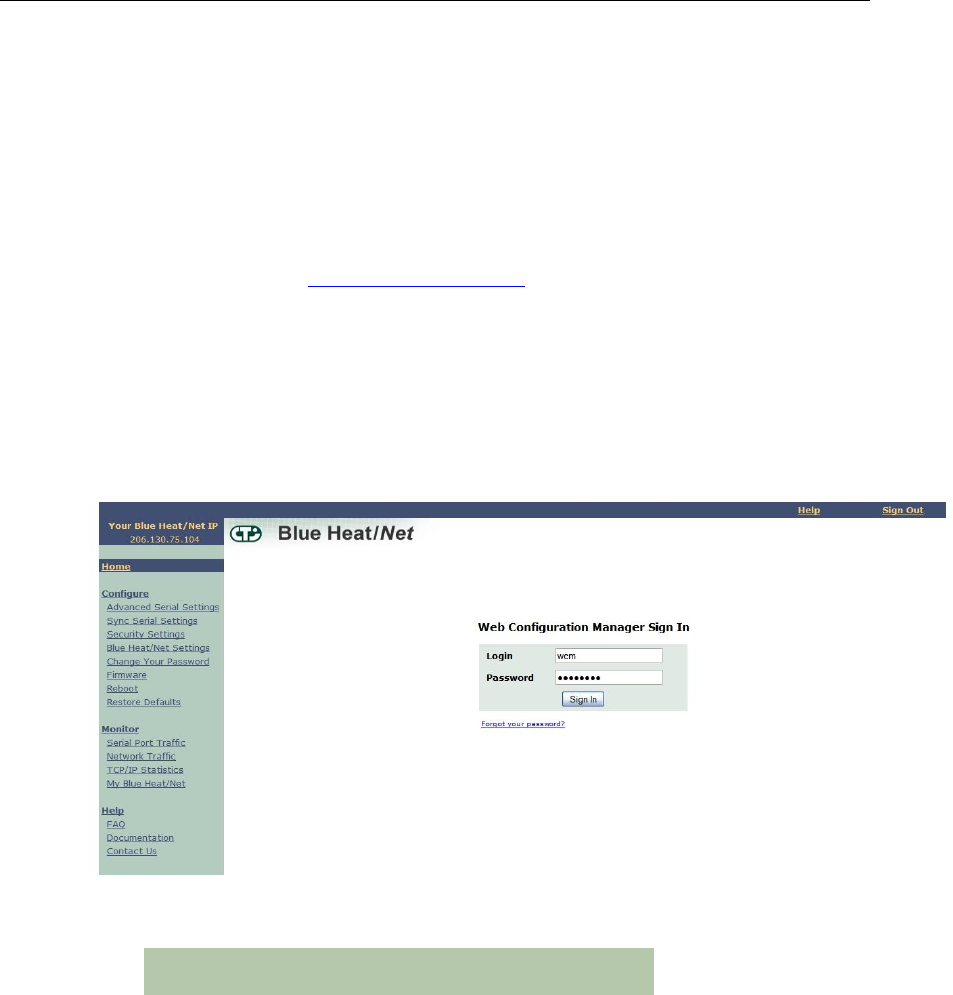
SCM Cabling requirements
SCM: Serial Configuration Manager
The Serial Configuration Manager is used to configure the Blue Heat/Net Sync via a serial port
and is discussed in greater detail later in this document. To access the Serial Configuration
Manager you will need to connect an RS-232 (V.28) serial cable from your standard computer
serial port to any RS-232 (V.28) port on the Blue Heat/Net Sync. The cabling required to
connect to the Blue Heat/Net Sync is as follows:
Figure 12: Blue Heat/Net Sync Serial Cable Connection Diagram
The key signal connections are RX, TX and GND. The other signals may not be required in your
application. If you are assembling your own SCM cable, we recommend that all of the above
connections be made.
Setting a Static or Dynamic IP Address
Prior to configuring the Blue Heat/Net Sync, you must set a static or dynamic IP address. The
default IP address of a new Blue Heat/Net Sync is 192.168.42.1. If there is a possibility that this
has been changed, you will need to find the current IP address setting before you begin.
The easiest way to get the IP address of your Blue Heat/Net Sync is as follows:
Follow the steps outlined in the section Installing the Blue Heat/Net Sync Configuration
Manager and noting your Blue Heat/Net Sync‟s IP number (i.e. A.B.C.D) using the Auto
Discover Blue Heat/Net Sync feature.
1- DCD
2- RX
3- TX
4- DTR
5- GND
6- DSR
7- RTS
8- CTS
9- RI
TX 2
RX 3
RTS 4
CTS 5
DSR 6
SR 7
DCD 8
DTR 20
RI 22
DB-25 M
Connects to Blue Heat/Net Sync
DB-9 F
Connects to PC

Connect Tech Blue Heat/Net Sync User Manual
22 Revision 0.03
Set the IP Address Using the Web Configuration Manager
NOTE: If you use the Windows Configuration Manager
and use Auto Discover to locate your Blue Heat/Net
Sync on the network, you can right-click and launch the
Web Configuration Manager from there.
You only need to use the route add command if you
choose not to use the Configuration Manager found on
the CD that accompanied your Blue Heat/Net Sync unit.
From the command prompt of your computer, run: route add A.B.C.0 mask 255.255.255.0 <current
IP of your host machine> Be sure to replace the .D from the Blue Heat/Net Sync‟s IP with a 0
(zero). Open your browser and put the Blue Heat/Net Sync‟s IP in the address bar (i.e. A.B.C.D)
This will open the WCM. Log in (default login is wcm and the default password is password)
and assign the static IP or change the IP to 0.0.0.0 if you are using a DHCP assigned IP.
Set the IP Address Using the Serial Configuration Manager
Insert your CD into the computer and complete the following steps:
1. Once your CD has been inserted, the Driver/Software Installation menu should appear. If it
doesn‟t, double-click on ctisetup.htm.
2. Click View in the Blue Heat/Net Sync Software section and then Connect in the Serial
Configuration Manager section. This will launch HyperTerminal that comes with Windows XP.
3. Unplug the power to the Blue Heat/Net Sync and plug it back in. Light indicators 1 to 4 will
blink sequentially. This sequential flashing will last for 30 seconds. You must log in during
this window.
4. During this sequential flashing, type the word password into the HyperTerminal window. Be
careful you do not miss the window of opportunity to enter the password.
5. You now have access to the Serial Configuration Manager (SCM). An scm> prompt is ready
to accept commands. If you do not see this prompt, unplug the power and repeat the steps above.
If you wish to set a dynamic IP address enter the following:
net dhcp=yes
save
exit
If you wish to set a static IP address, enter the following, substituting xxx.xxx.xxx.xxx with the
static IP you wish to assign:
net mip=xxx.xxx.xxx.xxx
save
exit
Close the HyperTerminal. You may now disconnect the DB-25 cable from your PC and connect
it to any serial device
.

Connect Tech Blue Heat/Net Sync User Manual
Revision 0.03 23
Blue Heat/Net Sync Configuration
The Blue Heat/Net Sync comprises several software components, each of which manages
various functions of the Blue Heat/Net Sync. The following is a breakdown of these
components.
Operating System Software
o Host Operating System Driver
o Configuration Manager
o Web browser (Host Operating System supplied)
Blue Heat/Net Sync Software (Firmware)
o Embedded Operating System (uClinux)
Kernel
Drivers
Ethernet
Serial
Flash
Blue Heat/Net Sync Ethernet Protocol Converter application (Ctid)
Web server (Boa)
Web pages
Telnet services
o PPP Client and PPP Server
o Bootloader
o Serial Configuration Manager (SCM) Application
o Configuration Data Space (CDS)
The following section describes in brief what each main component controls.
Host Operating System Driver
The host operating system driver performs the translation from a standard serial COM port
interface to the Blue Heat/Net Sync protocol (which is then delivered to the LAN as described
above).
Configuration Manager
This software manages and configures the relationships between the Blue Heat/Net Sync serial
ports and the COM port assignments of the Host Operating System.
Web Browser
The host operating system supplies a Web Browser to support the Web Configuration Manager
(WCM) used to change the configuration settings of Blue Heat/Net Sync units.
Embedded Operating System
The embedded operating system is uClinux.
Bootloader
This code first starts up the embedded processor of the Blue Heat/Net Sync from a power-up or
software initiated reboot. It then obtains the embedded operating system image (file) from one of
several locations and runs the operating system.
Serial Configuration Manager (SCM) Application
This application is used to change the configuration settings of Blue Heat/Net Sync units by
connecting to a serial port on the Blue Heat/Net Sync from a terminal (or terminal emulation

Connect Tech Blue Heat/Net Sync User Manual
24 Revision 0.03
program on a PC).
Configuration Data Space (CDS)
This is the area, in non-volatile (flash) memory, which stores the configuration parameters.
CDS (Configuration Data Space)
Description
The Blue Heat/Net Sync has a number of configuration parameters which are stored in a non-
volatile (flash memory) area. (See appendix for list of parameters).
The CDS area is stored redundantly in the flash memory along with a CRC-style checksum to
ensure data integrity.
Access to CDS Parameters
The parameters stored in the CDS can be changed through the use of the following configuration
tools:
SCM Serial Configuration Manager
WCM Web Configuration Manager
These three methods allow the user to change configuration parameters by the method that is
most convenient. In some cases several methods will be employed during different stages of the
setup of the Blue Heat/Net Sync. For example:
The SCM may be employed in the beginning when the unit is not connected to a network and
various networking parameters need to be set up prior to connection to a network.
WCM may be employed after the unit is connected to a network, possibly to modify other
settings related to serial ports, bootup settings or others.
More information about the operation of the SCM Command Reference and WCM (Web
Configuration Manager) follows.
NOTE: When CDS parameters are changed via the
SCM or WCM some settings will not take effect until the
Blue Heat/Net Sync is rebooted.

Connect Tech Blue Heat/Net Sync User Manual
Revision 0.03 25
SCM (Serial Configuration Manager)
Description
The Serial Configuration Manager is one of the applications you can use to access the
Configuration Data Space (CDS) settings of the Blue Heat/Net Sync. Since the CDS stores the
default serial port settings, it is important that the line mode is configured prior to first use.
Accessing the ports will not be possible otherwise.
Getting Access to the SCM
To access the SCM, simply connect a serial port terminal device (or a PC running a terminal
emulator program) to any of the serial ports on the Blue Heat/Net Sync and enter a correct
Password. A command prompt is then sent to the terminal and CDS parameters can be changed
using a command line style of entry.
Blue Heat/Net Sync has configurable line interfaces. Certain settings can affect access to the
SCM. The ports are scanned as follows:
The default line mode setting of all ports is Undefined. Under these conditions, the first two ports
are set to RS-232 mode during port scanning. Access to the SCM is available through these ports
only (you should set all ports to a known state prior to use).
When a port is set to something other than Undefined, any port with a setting of RS-232 or RS-
485 Full Duplex will be scanned. Otherwise, scanning is not performed and access to SCM is
not available.
NOTE: To access the Blue Heat/Net Sync via the SCM
your serial line interface settings must be at the default
values of 9600 baud, 8 data bits, no parity and 1 stop bit
(9600, 8, n, 1). No flow control is recommended.
In a situation where port scanning is not performed, you can still access the SCM using the push
button reset on the back of the unit. Follow the instructions in the section Activating the Special
Operations Mode and Default Settings to access the SCM in this situation
See the section which describes how the Blue Heat/Net Sync boots for a complete description of
the Bootup process of the Blue Heat/Net Sync and how to access the SCM.
SCM Command Reference
SCM commands are entered as strings of ASCII characters with options separated by whitespace
characters. The entire command line is terminated by a CR character or CR/LF character pair.
Command lines can be entered manually (via a terminal or a PC with terminal emulator
program) or sent from an application program.
If an SCM command is entered with no options specified, the command shows the syntax of its
options and the current setting of those options.
Brief Command List
boot Bootup settings
cfg SCM operational settings
exit Exits the SCM application (and optionally reboots the Blue Heat/Net Sync)
help Brief list of available commands and their syntax
info Blue Heat/Net Sync general information and flash verification
net Network settings

Connect Tech Blue Heat/Net Sync User Manual
26 Revision 0.03
save Save setting changes to non-volatile flash storage
update Download a new operating system via TFTP and flash,
(uClinux) and loader/SCM image.
Command Details
boot
Syntax: boot [mode=] [file=] [delay=]
Description: This command establishes the Blue Heat/Net Sync boot-up mode. For a detailed
description of the boot-up process of the Blue Heat/Net Sync, see How the Blue
Heat/Net Sync Boots Up in the Appendix.
Options: mode=
A comma-separated list of the following sub-options. Each sub-option is
preceded by either a + or a – to indicate if the sub-option is enabled or disabled.
±flash Enables or disables the ability to boot from the flash memory.
±bootp Enables or disables the ability to obtain the boot-up information from a
Server.
±tftp Enables or disables the ability to download and boot from a file located on
a Server.
file=
This option specifies the default file name used for the boot-up (if TFTP boot is
enabled) and also the default file name when using the flos command.
This can be any sequence of characters up to 128 characters in length. (The
default is BHNuClinux_vvv.gz, where vvv is the current version number of the
“Operating System image”).
delay=
This sets the time duration for accessing the SCM application. It can be set from
2 to 30 seconds, the default is 30. (See the section How the Blue Heat/Net Sync
Boots Up for more information).
cfg
Syntax: cfg [port=] [timeout=] [password=] [prompt=] [file=]
Description: Establishes the settings used by the SCM application to
modify its behavior.
Options: port=
Specifies the port number to scan for a password to gain entry in the SCM.
N = Scan just port N (N=1 to the number of ports on the unit).
255 = Scan all ports on the unit (default unless unit has programmable line
interfaces).
timeout=
Specifies the time duration allowed for a TCM (via telnet) session to be idle (no
activity) before the session is terminated.
0 to 1092 minutes
(default = 5)
Note: A setting of zero allows infinite timeout.
NOTE: The TCM function is currently not available with this
product.

Connect Tech Blue Heat/Net Sync User Manual
Revision 0.03 27
password=
This sets the password phrase, which is used to gain access to the SCM and
WCM modes of configuring the Blue Heat/Net. The default is “password”.
prompt=
This setting controls whether a password prompt (and other password entry
status information) is presented to the terminal. This prompting is helpful for
new users of the product but may present a problem when other devices are
connected to the serial port.
yes enables the password prompting (default)
no disables the password prompting
file=
This sets the file name used as a default when using the flldr command.
It can be any sequence of characters up to 128 characters in length. (The default
is “BHNloader_vvv.gz”, where vvv is the current version number of the
“Loader”).
exit
Syntax: exit [-nosave] [-no_reset][-login]
Description: This command is to exit the SCM and reboot the Blue Heat/Net Sync. If CDS
changes have been made a warning message is issued and the SCM will not exit.
Options: -nosave
Exit without saving changes (abandon changes).
-no_reset
Exit SCM without rebooting, maintaining the changes to settings for this session
only. (Booting is continued after the SCM is exited.)
-login
Exit without saving changes, and restart the SCM login process.
help
Syntax: help
Description: Displays a brief list of all the commands.
Options: There are no options for the help command. Please note that specific help for the
options of each command can be obtained by entering any command with a
single “?” argument. An example would be net ?
info
Syntax: info [-v]
Description: This command is used to show basic information about the Blue Heat/Net Sync
unit, like Serial Number and Version Numbers, and performs a confidence
(CRC and Decompression verification) test of the contents of the flash memory.
Options: -v
This option disables the confidence tests.
net
Syntax: net [network= | net=]

Connect Tech Blue Heat/Net Sync User Manual
28 Revision 0.03
[my_ip= | mip=]
[server_ip= | sip=]
[gateway_ip= | gip=]
[subnetmask= | snm=]
[broadcast_ip= | bcip=]
[dns_ip=]
[domain=]
[host name=1 host=]
[tcp=]
[mac=]
[dhcp=]
Description: Establishes the network settings.
Options: network= | net=
Sets the “network” portion of the IP address into my_ip, server_ip and
gateway_ip. The address entered is masked by the subnet mask setting before
being applied. This command is a shortcut for quickly setting all the IP
addresses of the unit. See note below.
my_ip= | mip=
This sets the IP address of the Blue Heat/Net Sync unit (default is 192.168.42.1).
See note below.
server_ip= | sip=
This sets the Server IP address. This address determines the address of the
Server to use when the Bootp and tftp mode is enabled (see boot command), and
also as the default Server address to use for the update commands (default is
0.0.0.0). See note below.
gateway_ip= | gip=
This sets the Gateway IP address. This address is used when the Bootp mode is
enabled, default is 0.0.0.0. See note below.
subnetmask= | snm=
This sets the Subnet mask IP address. (The default is 255.255.255.0) See note 1.
broadcast_ip= | bcip=
This sets the Broadcast IP address. This is used when the Bootp mode is
enabled. (The default 255.255.255.255). See note below.
dns_ip=
This sets the IP of Domain Name Server. (The default is 0.0.0.0). This must be
set to update the Blue Heat/Net Sync firmware automatically from Connect
Tech‟s anonymous ftp server.
domain=
This sets the Domain name of the unit. (The default is blueheat.net)
Host name=1 host =
This sets the Host name of the Blue Heat/Net Sync unit. (The default is
BHNssssssss, where “ssssssss” is the serial number of the unit).
tcp=
This sets the base TCP port number used for Host TCP/IP and UDP/IP
communications. The default is 49152 (0xC000)

Connect Tech Blue Heat/Net Sync User Manual
Revision 0.03 29
mac=
This displays the MAC address of the unit. (The default is 00:0C:8B:SS:SS:SS,
where SS:SS:SS is the hex value of the serial number of the unit). Note: The
MAC address cannot be changed, it can only be displayed.
dhcp=
This enables or disables DHCP support.
yes enables
no disables (default)
NOTES:
All IP addresses are entered in common IP address
notation: ddd.ddd.ddd.ddd where ddd is a decimal number
from 0 to 255.
IP address “my_ip, server_ip, gateway_ip and dns_ip” can
be entered right justified, meaning that the address
entered will be applied to the specified address starting
from the least significant digit, masked by the subnet
mask. For example:
If the subnet mask is set to 255.255.255.0, and the
following command is entered:
net net=12.23.34.00 mip=45 sip=56 gip=67 dns_ip=89
The following IP addresses result:
the Blue Heat/Net Sync unit will be
12.23.34.45
the Server will be 12.23.34.56
the Gateway will be 12.23.34.67
and the DNS IP will be 12.23.34.89
save
Syntax: save
Description: This command saves the setting changes into the CDS in the non-volatile (flash)
memory.
Options: (none)
update
Syntax: update <-os | -loader | -jffs> [server_ip= | sip=] [file=]
Description: Download and store (in flash memory) a new uClinux Operating System image
or a new Loader/SCM image. The download is conducted by a TFTP download
from a Server. After download the image file is checked as being a valid gzip
file (file is decompressed to validate its contents), and then the file is stored in
flash memory. The OS file is stored in flash in its compressed form, but the
Loader is stored uncompressed.
Options: -os | -loader | -jffs
Use -os to update the uClinux OS.
Use –loader to update the loader/SCM.
Use –jffs to update the JFFS system (Journaling Flash File System).

Connect Tech Blue Heat/Net Sync User Manual
30 Revision 0.03
server_ip= | sip=
Specify the Server IP address from which the file is to be downloaded.
file=
Specify the file name to download. If the –jffs option is chosen, then the file=
option is mandatory.
NOTE: After downloading, the image is checked to
ensure the file is correctly formatted. If the file is bad the
command exits. The version is checked against your
current version. If they match, you will be prompted to
choose if you wish to program the flash. Enter “y” to
continue. If the version is different, the new version
needs to be saved with the save command when the
update is finished.
When the JFFS is updated, all previous contents are
destroyed. Only use this option when updating to a Blue
Heat/Net Sync that supports Personality settings.
Connect Tech Blue Heat/Net Sync User Manual
Revision 0.03 31
WCM (Web Configuration Manager)
Signing In to the Web Configuration Manager
You will need to know the IP address of your Blue Heat/Net Sync unit before you use the Web
Configuration Manager. Use the Serial Configuration Manager to assign the Blue Heat/Net Sync
a valid IP address, or tell the Blue Heat/Net Sync to use DHCP to automatically obtain an IP
address. Please refer to the SCM Command Reference documentation for information on how to
do this.
Once you know your IP address, open your web browser and go to: http://_your_ip_address_/ or
http://www.hostname.com/
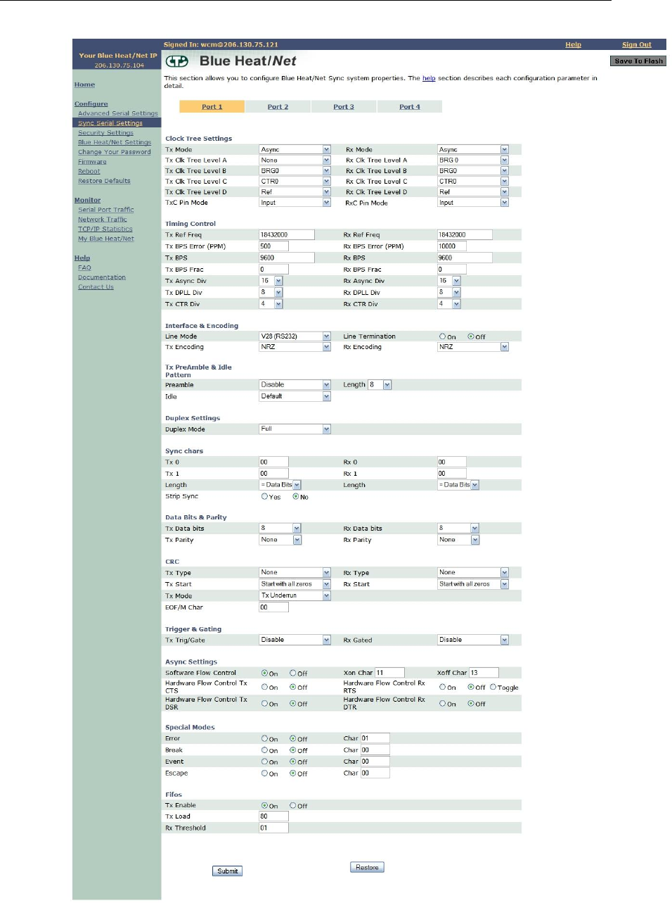
You will arrive at the Blue Heat/Net Sync Web Configuration Manager Sign In page. The
default username is wcm. Leave this name as is. The default password is password. Use this
username/password combination and click the Sign In button to log on to the Web Configuration
Manager.
Figure 13: Web Configuration Manager Sign In
Once you have signed in, you should immediately
change the default password.
At this point you should be directed to the Web Configuration Manager homepage.
To sign out of the Web Configuration Manager, just click on the Sign Out link on the upper
right hand side of the Web Configuration Manager.
Connect Tech Blue Heat/Net Sync User Manual
32 Revision 0.03
Figure 14: Blue Heat/Net Sync Settings

Connect Tech Blue Heat/Net Sync User Manual
Revision 0.03 33
Configure Advanced Serial Settings
The Web Configuration Manager also allows you to configure more advanced serial port
properties. These advanced properties will allow you to configure the XOn Character, XOff
Character, Break Character, Escape Character, Error Character and Event Character, and
Transmit Load Setting for each serial port.
Further, you will be able to specify whether you want to enable Null Stripping or RTS Toggle
for a particular port as well as the option to enable or disable the Break, Event and Error
characters.
By default, all advanced serial properties are disabled. You should only use these advanced
properties if you require them.
You are required to use the ASCII representation of characters using the respective hexidecimal
values. For example, if you wanted your XOn character to be capital 'A', you would specify a
hex value of 41.
We have provided you with an ASCII table on the Advanced Serial Port Properties page for your
convenience. Click on the ASCII Table link, and an ASCII table will open in a new window.
Each serial port parameter has been abbreviated due to space constraints. We have provided
another link which describes the abbreviated parameter descriptions. Click on the Parameter
Descriptions link, and a new window will open which contains a description of each parameter.
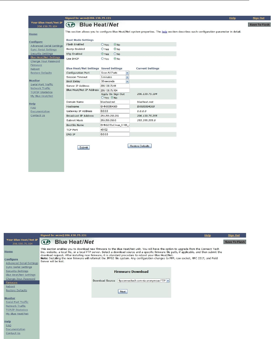
Configure Blue Heat/Net Sync Settings
This section provides various Blue Heat/Net Sync Configuration options, and shows you the
saved versus current settings. The details for each configuration option are provided below:
• Flash Enabled: This option enables or disables the ability of the Blue Heat/Net Sync to
boot-up from flash memory.
• Bootp Enabled: This option enables or disables the Blue Heat/Net‟s ability to obtain
boot-up information from the server (see "Server IP Address" below).
• TFTP Enabled: This option enables or disables the ability to download and boot from a
file located on a server (see "Server IP Address" below).
• DHCP Enabled: This option enables or disables the use of DHCP. If DHCP is enabled,
the Blue Heat/Net Sync will attempt to automatically obtain an IP address. If DHCP is
disabled, you must manually specify an IP address for the Blue Heat/Net.
• Configuration Port: This option sets the port to scan for the password to gain entry into
the Serial Configuration Manager. You can specify a particular port, or specify the Scan
All Ports option. In this case the Blue Heat/Net Sync will scan all ports for the password
when the Blue Heat/Net Sync is booting. The default setting is Scan All Ports.
• Session Timeout: This option specifies the time allowed between web page navigation.
The default session timeout is 5 minutes. This means if the Web Configuration Manager
has not received any requests for more than 5 minutes, you will be automatically logged
out. You can set the timeout from 1 minute to 2 hours, or disable the session timeout all
together by selecting the Disable Timeout option.
• Boot Delay: This option specifies time allowed for gaining access to the Serial
Configuration Manager while the Blue Heat/Net Sync is booting. The time ranges from
2 seconds to 30 seconds. The default setting is 30 seconds.

Connect Tech Blue Heat/Net Sync User Manual
34 Revision 0.03
• Server IP Address: This option sets the server IP address. This is used as the Server
address to use when bootp mode or TFTP mode is enabled. The default Server IP
address is 0.0.0.0
• Blue Heat/Net Sync IP Address: This option sets the IP address of your Blue Heat/Net.
The default IP address for your Blue Heat/Net Sync is 192.168.42.1
• Domain Name: This option sets the domain name of your Blue Heat/Net. The default
domain name is blueheat.net.
• Host Name: This option sets the hostname of your Blue Heat/Net. The default hostname
is BHNssssss, where ssssss is your Blue Heat/Net Sync serial number.
• Gateway IP Address: This option sets the Gateway IP address for your Blue Heat/Net.
The default Gateway IP address is 0.0.0.0
• Broadcast IP Address: This option sets the Broadcast IP address. The default Broadcast
IP address is 255.255.255.255.
• Subnet Mask: This option sets the Subnet mask IP address. The default Subnet mask IP
address is 255.255.255.0.
• Bootfile Name: This option specifies the default file name which will be used for Blue
Heat/Net Sync boot-up, if TFTP is enabled. If TFTP is enabled, the Blue Heat/Net Sync
will attempt to download the bootfile you specify from a Server IP address you specify
(see "Server IP Address" above). The bootfile name should reference a valid uClinux
kernel image. If TFTP is enabled, the Blue Heat/Net Sync unit will attempt to download
this image, and will also attempt to decompress the image and run it.
• TCP Port: This option allows you to change the starting local TCP port that is used to
service clients connecting to the Blue Heat/Net Sync unit. The default TCP port is
49152. When altering the TCP port on the Blue Heat/Net Sync unit, you must also alter
it on the user‟s side.
• Domain Server IP Address: This option sets the Domain Name Server IP address. The
default DNS IP address is 0.0.0.0.
After you've made any necessary configuration changes, click the Submit button at the bottom of
the page. A confirmation page will show up confirming the Blue Heat/Net Sync changes.
Connect Tech Blue Heat/Net Sync User Manual
Revision 0.03 35
Figure 15: Configuring Blue Heat/Net Sync Settings
Configure Firmware
This section enables you to download new firmware to the Blue Heat/Net Sync unit. Select a
download source and a specific firmware file path, if applicable, and then submit the download
request. This section also provides a link to reboot your Blue Heat/Net. This is standard
procedure after installing new firmware.
Figure 16: Firmware Upgrades/Downloads
Restore Defaults
The Restore Defaults page enables you to quickly reset all or some of the default basic,
advanced, security, Blue Heat/Net Sync or system settings of your Blue Heat/Net Sync.
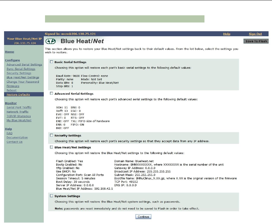
Connect Tech Blue Heat/Net Sync User Manual
36 Revision 0.03
NOTE: This function is not currently operational.
Figure 17: Restore Default Settings
Saving To Flash
When you make configuration changes, the changes are stored temporarily in memory. If you
reboot your Blue Heat/Net Sync at this point, any configuration changes you made will be lost.
To permanently save your changes, you need to save them to flash. In order to do this, click the
Save to Flash button on the upper right-hand side of the Web Configuration Manager page.
If there are changes that need to be saved, the Save To Flash button will be yellow. Click the
Submit button to permanently save any configuration changes to the flash memory so they will
be present when you reboot your Blue Heat/Net.

Connect Tech Blue Heat/Net Sync User Manual
Revision 0.03 37
Figure 18: Saving To Flash
If you haven't made any configuration changes, the Save To Flash button will remain grey.
Monitoring Your Blue Heat/Net
The Blue Heat/Net Sync WCM lets you monitor serial port activity, network traffic and TCP/IP
statistics as well as providing hardware and software details for your Blue Heat/Net Sync unit.
Monitor Serial Port Traffic
This page allows you to monitor your serial port traffic. For each Blue Heat/Net Sync port, you
can view the number of bytes transmitted, received, whether the port is using flow control, if
there are any Parity/Framing/Overrun errors, and which remote IP address is connected to your
serial port.
If ports are active (open) they are shown in green, while inactive (closed) ports are shown in
grey.
NOTE: This function is not currently operational.
Figure 19: Monitoring Serial Port Activity
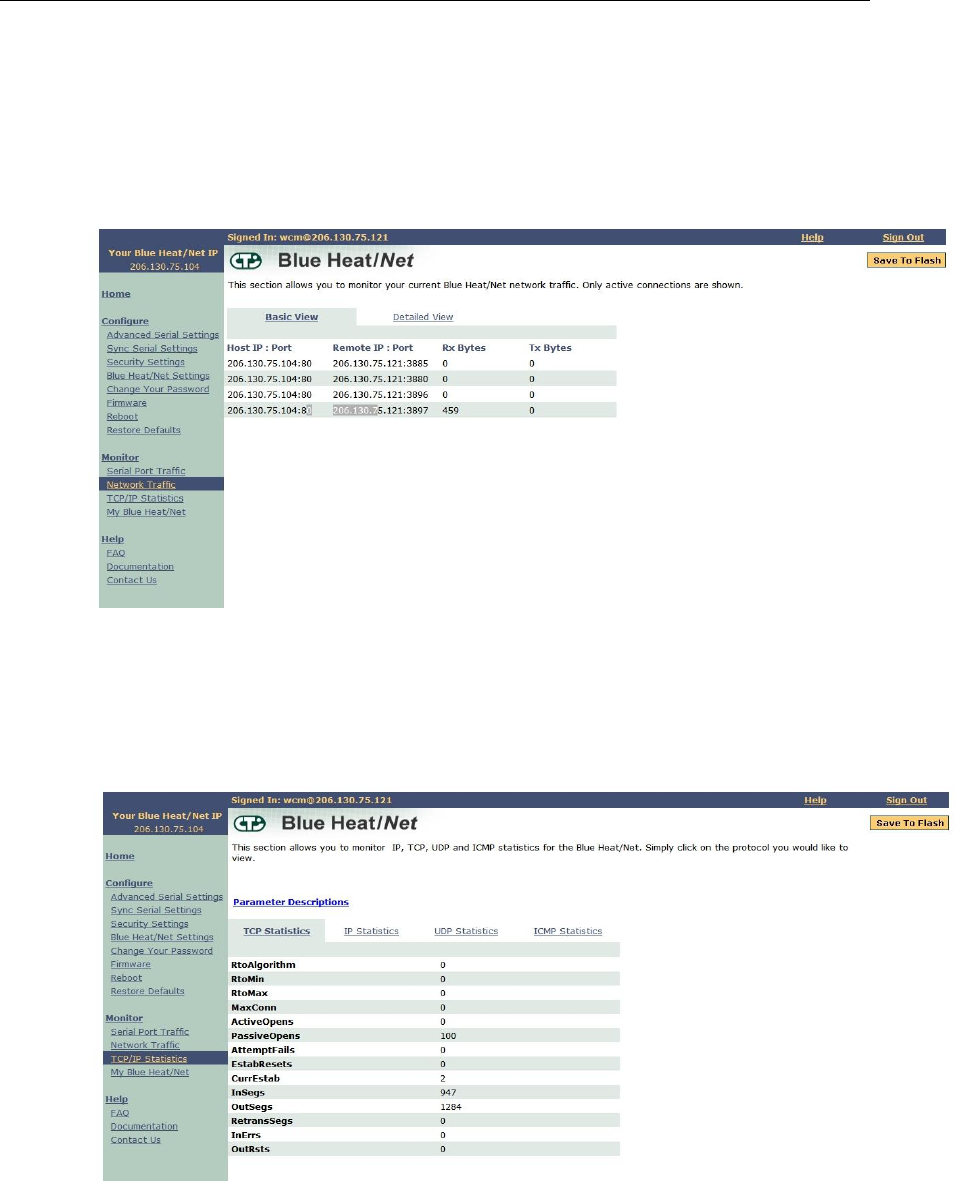
Connect Tech Blue Heat/Net Sync User Manual
38 Revision 0.03
Monitor Network Traffic
This page allows you to view all network activity on your Blue Heat/Net. For each active
network connection, you can view the local IP address and port, the remote IP address and port,
the status of the connection, the protocol being used, as well as the number of queued transmit
and receive bytes.
Figure 20: Monitoring Network Traffic
Monitor TCP/IP Statistics
This page allows you to view TCP, IP, UDP and ICMP statistics for your Blue Heat/Net Sync.
This page also has a link which describes each of the network statistic parameters. Simply click
on the Parameter Descriptions link, and a new window will open up which contains a description
of each parameter.
Figure 21: Monitoring TCP/IP Statistics
My Blue Heat/Net Sync
This page provides you with three display options: Hardware, Software and Performance.
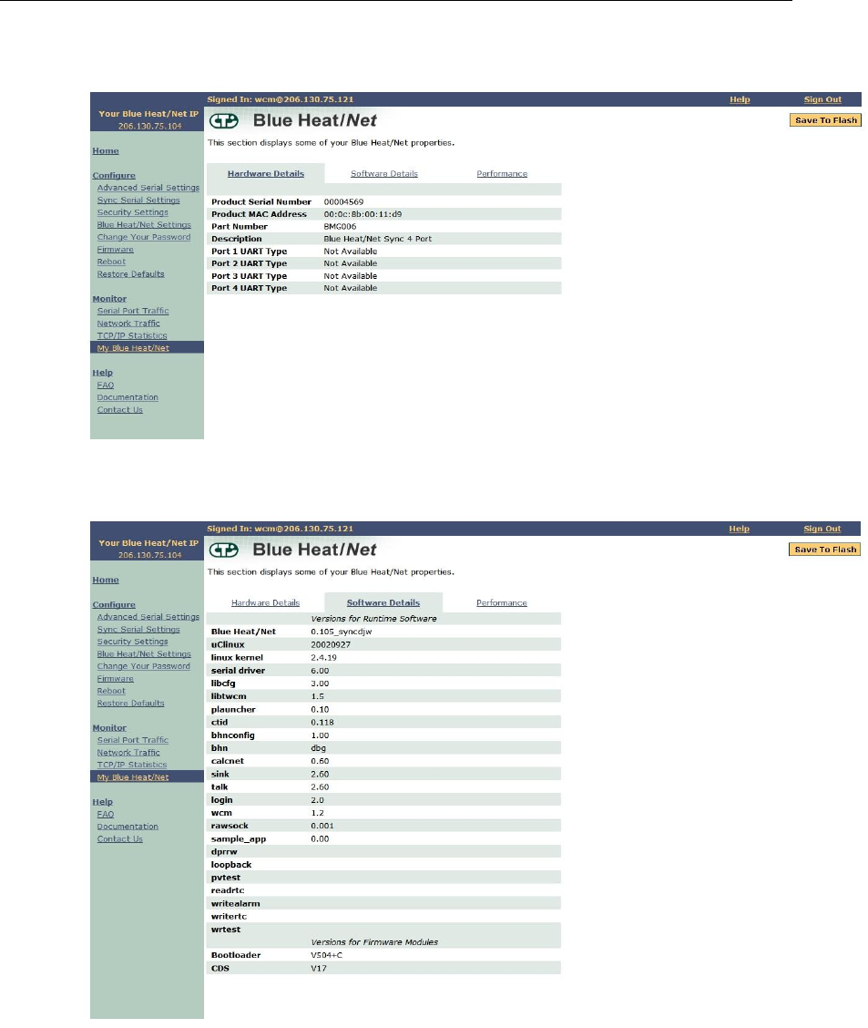
Connect Tech Blue Heat/Net Sync User Manual
Revision 0.03 39
Use this link to find information such as device serial number, runtime software versions and
firmware versions.
Figure 22: My Blue Heat/Net Sync Hardware Details
Figure 23: My Blue Heat/Net Sync Software Details
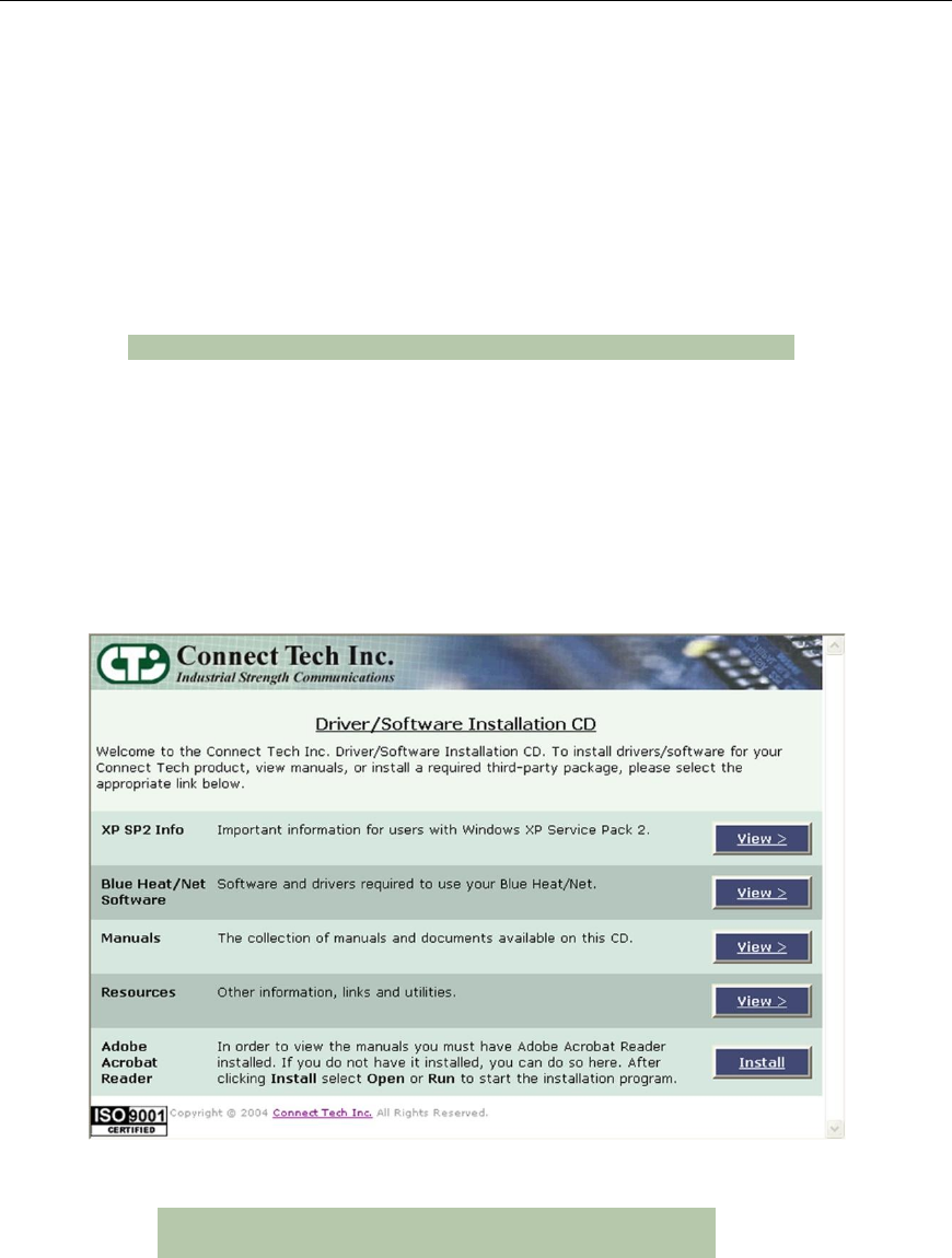
Connect Tech Blue Heat/Net Sync User Manual
40 Revision 0.03
Software Installation for Windows
The Blue Heat/Net Sync is designed for easy installation and set up.
This section deals with installing and using the Blue Heat/Net Sync software to communicate
with your Blue Heat/Net Sync.
To do so, you will use the CD included with the Blue Heat/Net Sync to install the Configuration
Manager on your computer. The Blue Heat/Net Sync Configuration Manager will allow you
install the Blue Heat/Net Sync on your local system, and map and configure the Blue Heat/Net
Sync‟s communication ports.
NOTE: Software support for Windows is still in development
Installing the Blue Heat/Net Sync Configuration Manager
The Blue Heat/Net Sync Configuration Manager is a tool to control your Blue Heat/Net Sync
from your local Windows operating system. To install the Blue Heat/Net Sync Configuration
Manager on your computer, insert the CD provided with your Blue Heat/Net Sync into the disk
drive.
You should see this window in your browser:
Figure 24: Blue Heat/Net Sync Driver/Software Installation CD
NOTE: Windows XP SP2 users should read the SP2 info
prior to installing the Configuration Manager
Select View from the Blue Heat/Net Sync software. It will bring you to the following screen.
Click Install to begin the Configuration Manager installation. Ensure you choose Open or Run
when the File Download window appears and asks if you‟d like to open the file or save it to
your computer.
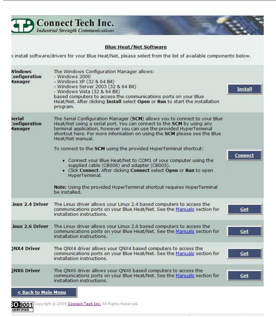
Connect Tech Blue Heat/Net Sync User Manual
Revision 0.03 41
Figure 25: Blue Heat/Net Sync Software Installation Screen
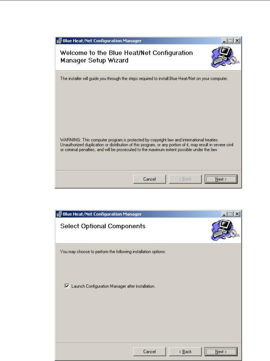
Connect Tech Blue Heat/Net Sync User Manual
42 Revision 0.03
The Blue Heat/Net Configuration Manager Setup Wizard will begin. Click Next to start.
Next you will have the option to launch the configuration manager after installation.
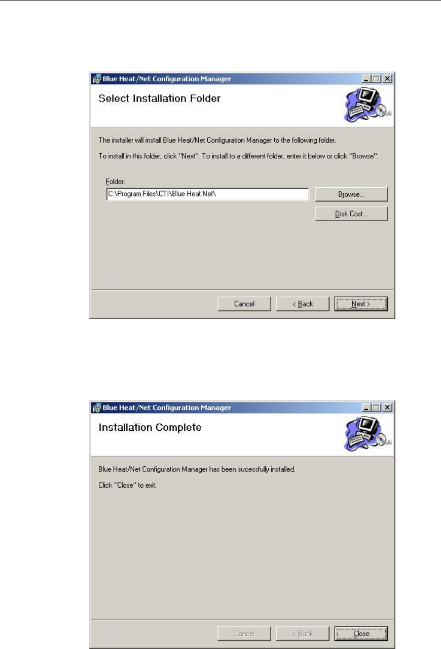
Connect Tech Blue Heat/Net Sync User Manual
Revision 0.03 43
The installer will install the Configuration Manager into C:\Program Files\CTI\Blue Heat Net. If
you‟d prefer an alternate location, specify in the space provided, or click Browse to locate the
new folder. Click Next.
You will then be prompted to confirm you wish to install the Configuration Manager. Select
Next to begin.
When the Installation Complete window appears, the Configuration Manager has been
successfully installed. Click Close to exit the installation wizard.
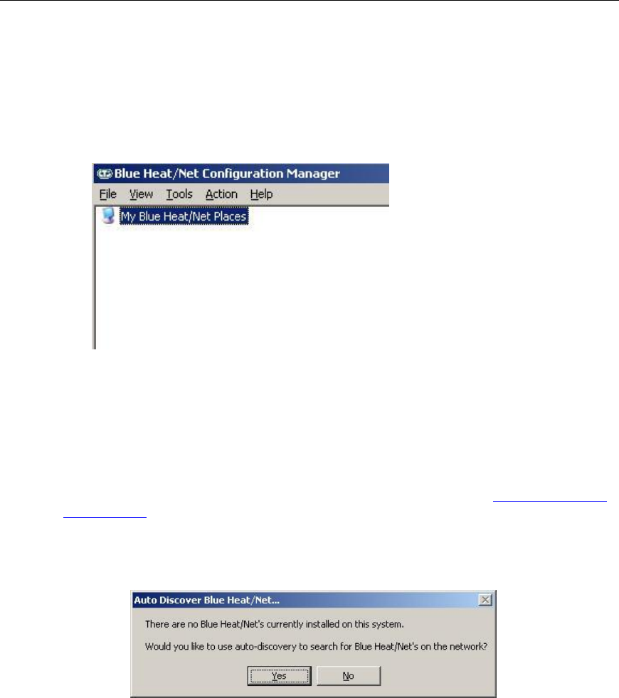
Connect Tech Blue Heat/Net Sync User Manual
44 Revision 0.03
Running the Configuration Manager
If you chose the option to launch the Blue Heat/Net Sync Configuration Manager after
installation, the main Configuration Manager window should now be open on your screen. If
you did not, you can launch it from the CTI default folder or whichever folder you chose during
the installation.
Figure 26: My Blue Heat/Net Sync Places Screen
Device Installation
Select My Blue Heat/Net Sync Places from the main Configuration window. (NOTE: If there is no
Blue Heat/Net Sync installed, you will be prompted to auto discover a Blue Heat/Net Sync on
your network. If you choose to do so, click Yes and then jump ahead to the Auto Discover Blue
Heat/Net Sync section)
Right-click on My Blue Heat/Net Sync Places or click on the Action menu to pull up the sub menu
options.
There are three ways to install a Blue Heat/Net Sync device: Configure Default Blue Heat/Net
Sync, Add New Blue Heat/Net Sync or Auto Discover Blue Heat/Net Sync.
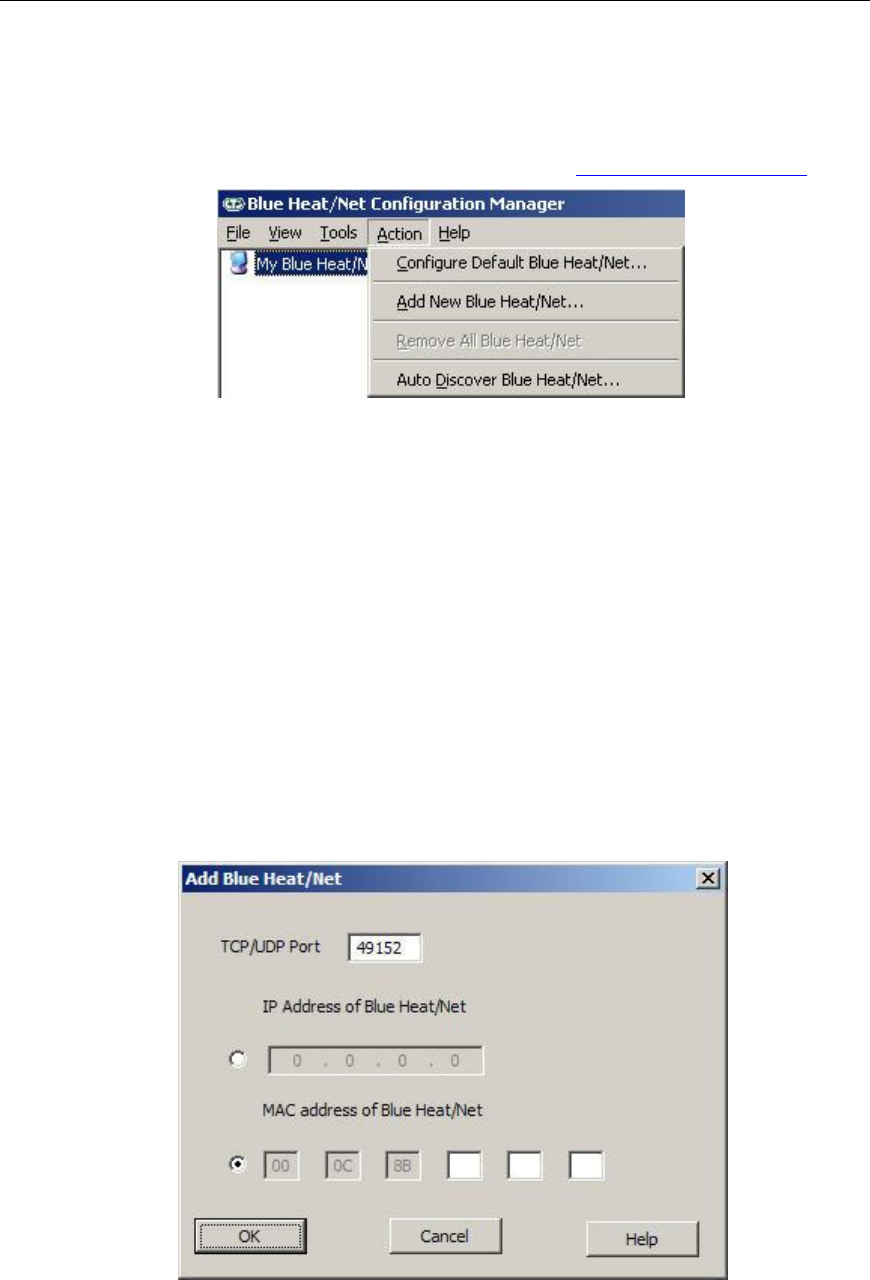
Connect Tech Blue Heat/Net Sync User Manual
Revision 0.03 45
Configure Default Blue Heat/Net Sync
You can choose this option when your Blue Heat/Net Sync still has a factory default IP address
of 192.168.42.1. It will launch the Web Configuration Manager for this IP address, enabling
you to configure your Blue Heat/Net Sync as outlined in the Web Configuration Manager.
Figure 27: Add or Auto Discover Blue Heat/Net Sync Menu Screen
Add New Blue Heat/Net Sync
You can add a Blue Heat/Net Sync by specifying its IP address or MAC address.
If you specify an IP address, the Configuration Manager will connect to that specific Blue
Heat/Net Sync and the configuration information for installation. If it cannot connect, it will not
install the unit. The Blue Heat/Net Sync may get the IP address from DHCP server or it can be
manually fixed. The Configuration Manager will use 49152 as the default TCP port. This value
is configurable.
If you specify a MAC address (located on the underside of the device), the Configuration
Manager will use the auto-discover mechanism to retrieve the information for installation. The
auto-discover mechanism uses UDP broadcast, so the unit must be located on the local network
to install via MAC address. The Configuration Manager will use 49152 as the default UDP port.
This value is configurable.
Figure 28: Add Blue Heat/Net Sync Screen
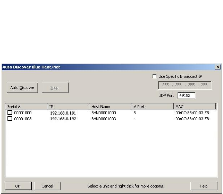
Connect Tech Blue Heat/Net Sync User Manual
46 Revision 0.03
Auto Discover Blue Heat/Net Sync
The auto discover will broadcast a message to all the Blue Heat/Net Sync devices on your
network. Upon receiving the broadcast packet, the Blue Heat/Net Sync device will respond.
Click the Auto Discover button to search for Blue Heat/Net. The searching domain can be
changed by checking Use Specific Broadcast IP and entering an IP address domain in the IP
address box. The broadcast packet will use the default UDP port 49152, but it can be changed in
the Blue Heat/Net Sync configuration. The Stop button will end the search.
Figure 29: Auto Discover Blue Heat/Net Sync Screen
Auto Discover will list any Blue Heat/Net Sync on your network, along with Blue Heat/Net
Sync's serial number, IP address, host name, number of available ports and the MAC address.
To install a Blue Heat/Net Sync check the appropriate box under Serial # column and then click
OK. Right click for more options, including the option to launch the Web Configuration
Manager.

Connect Tech Blue Heat/Net Sync User Manual
Revision 0.03 47
Firmware Upgrades
If you need to re-install your current firmware, it is located in the firmware directory of the CD
you received with your Blue Heat/Net Sync.
Newer firmware versions are available from Connect Tech‟s website,
http://www.connecttech.com/asp/Support/DownloadZone.asp. Choose Blue Heat/Net Sync
product. Ensure the following parameters are set: mip, sip, gip and dns_ip using the SCM. To
upgrade your Blue Heat/Net Sync firmware, you can use any of the following three methods,
depending on your preference.
Upgrade using WCM (Web Configuration Manager)
The Web Configuration Manager is the easiest way to upgrade your firmware. Simply log onto
the WCM as described in the WCM (Web Configuration Manager) section, and click on the
Firmware link on the left menu. This will bring you to the Firmware page. You will have the
option to upgrade from the remote CTI website, or to download the upgrade from a local FTP
server.
If you choose to upgrade via a local FTP server, copy the firmware (*.tar) file to the anonymous
directory of a local FTP server. If you do not have a local FTP server, contact your system
administrator to set one up.
Upgrade using SCM (Serial Configuration Manager)
The SCM method of upgrading is used when the Blue Heat/Net Sync does not boot properly.
You can reinstall your original firmware from the supplied CD, or you can download any newer
versions that exist from the CTI website in the
http://www.connecttech.com/asp/Support/DownloadZone.asp or go directly to the FTP site as
indicated below.
You will need the use of a TFTP server. (Contact your system administrator to obtain access to
a TFTP server). Download the most recent firmware components from the FTP site
ftp://ftp.connecttech.com/pub/BHN/ . These files include BHNuClinux_X.XX.gz,
BHNloader_VXXX.gz and BHNjffs2_X.XX.gz.
These files contain all of the Blue Heat/Net Sync firmware. Follow the update command
instructions for the SCM Command Reference to update each component.

Connect Tech Blue Heat/Net Sync User Manual
48 Revision 0.03
Software Development
Hardware Information
The information provided in this section will offer data pertaining to the hardware components present
within the Blue Heat/Net Sync unit. Hardware information documentation will encompass hardware
resources, base address map, memory map and table, as well as, PLD registers.
Hardware Resources
The hardware resources available for use in software development for the Blue Heat/Net Sync, include;
chip selects, interrupts, ColdFire MCF5272 GPIO.
Chip Selects
Chip
Select *
Usage
Data Bus
Width
Address Range
Cycle Termination
/CS0
This chip select is used
to boot the CPU from
the Flash. The Flash is
8M Byte in size.
16 bits
0xFE00 0000 –
0xFE80 0000
8 Mbytes
- Internal WS logic.
- 5 wait states.
/CS1
Used to select the
IUSCs and the internal
PLD registers.
16 bits
0x4000 0000 –
0x4000 2000
8 kbytes
External /TA signal
/CS2
Dual Ported RAM. 32k
Bytes total size
16 bits
0x8000 0000 –
0x8000 8000
32 kbytes
External /TA signal
/CS2
Undefined. For future
expansion or debugging
purposes. Available on
debug header P11 on
page 8 of Schematic
Undefined, but
could be 8 or
16 bits
Undefined.
Undefined.
/CS7
Used for SDRAM. The
SDRAM is 16M Bytes
in size.
32 bits
0x0000 0000-
0x0100 0000
16 Mbytes
Internal WS logic and
SDRAM controller.
Table 5: Chip Selects

Connect Tech Blue Heat/Net Sync User Manual
Revision 0.03 49
Interrupts
INT *
Usage
/INT1, /INT2
IUSC logically or-ed interrupts. IUSC Interrupts can be muxed to any of the two INTs.
One use is to mux all ports configured for Async mode to one IRQ and all ports
configured for Sync mode to another interrupt. This should facilitate better software
architecture and operation.
/INT3
PLD Interrupt. To support miscellaneous PLD section functions.
/INT6
Ethernet PHY Interrupt. Same PHY as other MCF5272 based Blue Heat/Net models.
* INTs are active low. Unused interrupts are pulled up to V+.
Table 6: Interrupts
ColdFire MCF5272 GPIO
GPIO Bit(s) *
Direction
Usage
PA0 – PA4,
PA6
Undefined
Undefined. For future expansion or debugging purposes. Available on
debug header P11 on page 8 of Schematic
PA5
Output
CPU Status LED.
1 = LED Off
0 = LED On.
PA8 – PA11
Input
PCB ID. Should be 0x4, for BHN Sync 4 Port.
PA13
Input
Pushbutton input.
1 = not pushed
0 = pushed
PA14
Output
Software forced hardware reset.
1 = Not reset. When setting up this GPIO, be sure to set port to a „1‟
before changing direction to output.
0 = forces a hardware reset
Table 7: ColdFire MCF5272 GPIO
* All unused GPIO is pulled up with a pullup resistor.
Base Address Map
Item
Address Range (hex)
ColdFire MBAR
1000 0000
Internal SRAM (4k Byte)
2000 0000
IUSC 0
4000 0000
IUSC 1
4000 0400
IUSC 2
4000 0800
IUSC 3
4000 0C00
PLD registers
4000 1000
DPR (32k Byte SRAM)
8000 0000
Flash (8 M Byte )
FE00 0000
Table 8: Base Address Map

Connect Tech Blue Heat/Net Sync User Manual
50 Revision 0.03
Memory Map of IUSC and PLD Functions
ColdFire (5272) Bus:
A ColdFire CS# signal is used to select the entire region, setup with the following attributes…
8K (8192) byte region
16 Bit bus
Use TA# signal to terminate the bus cycle (this places wait state generation in the hands of
the PLD logic).
o CSBR.EBI = 00b selects 16/32 SRAM/ROM mode
o CSBR.BW = 10b selects 16 bit bus
o CSOR.WS = 0x1F selects the use of the TA# signal
o CSOR.BAM = as required selects size of region
o CSOR.BA = as required sets 32 bit Base address of the region
o
ColdFire Bus Addresses A0 through A12 are used to “address” all items
A[12] divides the region into 2 (4096 byte) areas
IUSC Access:
A[12] Must be zero (0).
A[11..9] Are decoded into 8 functions which access the 4 IUSC devices
A11
A10
A9
IUSC
selected
Function
Notes
0
0
0
0
Register Read/Write
0
0
1
0
Interrupt Acknowledge
Write not allowed [1]
0
1
0
1
Register Read/Write
0
1
1
1
Interrupt Acknowledge
Write not allowed [1]
1
0
0
2
Register Read/Write
1
0
1
2
Interrupt Acknowledge
Write not allowed [1]
1
1
0
3
Register Read/Write
1
1
1
3
Interrupt Acknowledge
Write not allowed [1]
[1] A write to these addresses are ignored, but the ColdFire bus cycle is properly terminated.
A[8] Is “connected” (inverted) to the IUSC S//D pin
0 = Selects “Serial Controller” registers in the IUSC device.
1 = Selects “DMA” registers in the IUSC device.
A[7] Is “connected” to the IUSC D//C pin
0 = Selects Serial “Control” registers
1 = Selects Serial “Data” registers
A write places data into the Transmitter FIFO
A read removes data from the Receiver FIFO
The word “connected” above, is used loosely to mean… The address bit is routed from the
ColdFire bus to the indicated IUSC pin via the logic in the PLD.
A[6] Is not used (set to zero for all operations).

Connect Tech Blue Heat/Net Sync User Manual
Revision 0.03 51
A[5..1] Addresses IUSC registers (see Memory Map Table below).
A[0] Not used explicitly, A0 (along with BS0# and BS1#) select byte size portions of IUSC
registers.
PLD Resource Access:
A[12] Must be one (1).
A[11..5] Are not used.
A[4..2] Are decoded into selections of internal PLD “registers”.
A4
A3
A2
Function
Notes
0
0
0
Real Time Clock
32 bit read/write (16 bit portions
also accessible)
0
0
1
LED Control
16 bit read/write only
0
1
0
Port-1 Line I/F control
16 bit read/write only
0
1
1
Port-2 Line I/F control
16 bit read/write only
1
0
0
Port-3 Line I/F control
16 bit read/write only
1
0
1
Port-4 Line I/F control
16 bit read/write only
1
1
0
Control
16 bit read/write only
1
1
1
Status
16 bit read only
A[1] Is used to select the 16 bit portions of the Real Time Clock register.
A[0] Is not used.
PLD Memory Map Table
Address
Offset
(in hex)
Area (item)
Accessed
Register
Accessed
Notes
IUSC Area
IUSC-0
000
IUSC-0 Sreg [1]
CCAR
002
IUSC-0 Sreg
CMR
004
IUSC-0 Sreg
CCSR
006
IUSC-0 Sreg
CCR
008
IUSC-0 Sreg
PSR
00A
IUSC-0 Sreg
PCR
00C
IUSC-0 Sreg
TMDR
00E
IUSC-0 Sreg
TMCR
010
IUSC-0 Sreg
CMCR
012
IUSC-0 Sreg
HCR
014
IUSC-0 Sreg
IVR
016
IUSC-0 Sreg
IOCR
018
IUSC-0 Sreg
ICR
01A
IUSC-0 Sreg
DCCR
01C
IUSC-0 Sreg
MISR
01E
IUSC-0 Sreg
SICR
020
IUSC-0 Sreg
RDR(TDR)
8/16 bit Serial Data (byte/word)

Connect Tech Blue Heat/Net Sync User Manual
52 Revision 0.03
Address
Offset
(in hex)
Area (item)
Accessed
Register
Accessed
Notes
Writes go to the Transmitter FIFO
Reads come from the Receiver FIFO
022
IUSC-0 Sreg
RMR
024
IUSC-0 Sreg
RCSR
026
IUSC-0 Sreg
RICR
028
IUSC-0 Sreg
RSR
02A
IUSC-0 Sreg
RCLR
02C
IUSC-0 Sreg
RCCR
02E
IUSC-0 Sreg
TCOR
030
IUSC-0 Sreg
TDR(RDR)
8/16 bit Serial Data (byte/word)
Writes go to the Transmitter FIFO
Reads come from the Receiver FIFO
032
IUSC-0 Sreg
TMR
034
IUSC-0 Sreg
TCSR
036
IUSC-0 Sreg
TICR
038
IUSC-0 Sreg
TSR
03A
IUSC-0 Sreg
TCLR
03C
IUSC-0 Sreg
TCCR
03E
IUSC-0 Sreg
TC1R
040 07F
---
---
Aliases of addresses 00 3F
080->09F
IUSC
Data FIFO‟s
(32 bytes)
RDR/TDR
16 bit Serial Data transfers ONLY!!
Writes go to the Transmitter FIFO
Reads come from the Receiver FIFO
(useful for block data movements)
0A0 0FE
Aliases of 080->9F
100
IUSC-0 Dreg [2]
DCAR
102
IUSC-0 Dreg
TDMR
104
---
---
Reserved, do not access
106
IUSC-0 Dreg
DCR
108
IUSC-0 Dreg
DACR
10A 111
---
---
Reserved, do not access
112
IUSC-0 Dreg
BDCR
114
IUSC-0 Dreg
DIVR
116
---
---
Reserved, do not access
118
IUSC-0 Dreg
DICR
11A
IUSC-0 Dreg
CDIR
11C
IUSC-0 Dreg
SDIR
11E
IUSC-0 Dreg
TDIAR
120 129
---
---
Reserved, do not access
12A
IUSC-0 Dreg
TBCR
12C
IUSC-0 Dreg
TARL
12E
IUSC-0 Dreg
TARU
130 139
---
---
Reserved, do not access
13A
IUSC-0 Dreg
NTBCR
13C
IUSC-0 Dreg
NTARL
13E
IUSC-0 Dreg
NTARU
140 181
---
---
Reserved, do not access
182
IUSC-0 Dreg
RDMR
184 19D
---
---
Reserved, do not access
19E
IUSC-0 Dreg
RDIAR

Connect Tech Blue Heat/Net Sync User Manual
Revision 0.03 53
Address
Offset
(in hex)
Area (item)
Accessed
Register
Accessed
Notes
1A0 1A9
---
---
Reserved, do not access
1AA
IUSC-0 Dreg
RBCR
1AC
IUSC-0 Dreg
RARL
1AE
IUSC-0 Dreg
RARU
1B0 1B9
---
---
Reserved, do not access
1BA
IUSC-0 Dreg
NRBCR
1BC
IUSC-0 Dreg
NRARL
1BE
IUSC-0 Dreg
NRARU
1C0 1FF
---
---
Reserved, do not access
200
IUSC-0
Interrupt Acknowledge (read only)
202 3FF
IUSC-0
Aliases of 200
IUSC-1
400 5FF
IUSC-1
As Above
Same registers as addresses 000 1FF
600
IUSC-1
Interrupt Acknowledge (read only)
602-7FF
IUSC-1
Aliases of 600
IUSC-2
800 9FF
IUSC-2
As Above
Same registers as addresses 000 1FF
A00
IUSC-2
Interrupt Acknowledge (read only)
A02 BFF
IUSC-2
---
Aliases of A00
IUSC-3
C00 DFF
IUSC-3
As Above
Same registers as addresses 000 1FF
E00
IUSC-3
---
Interrupt Acknowledge (read only)
E02 FFF
IUSC-3
---
Aliases of E00
PLD Area
See “PLD Registers” for details.
1000
RTCU
Real Time Clock Upper
1002
RTCL
Real Time Clock Lower
1004
LEDC
LED Control
1006
Alias of 1004
1008
LIFC1
Port-1 Line I/F control
100A
Alias of 1008
100C
LIFC2
Port-2 Line I/F control
100E
Alias of 100C
1010
LIFC3
Port-3 Line I/F control
1012
Alias of 1010
1014
LIFC4
Port-4 Line I/F control
1016
Alias of 1014
1018
PLD_CNTRL
Control Bits
101A
Alias of 1018
101C
PLD_STATUS
Status bits
101E
Alias of 101C
1020 1FFF
Unused
[1] Sreg = Serial Register
[2] Dreg = DMA Register

Connect Tech Blue Heat/Net Sync User Manual
54 Revis
PLD Registers:
Offset
Reg Name
R/W
Valid
Bit
Bit Descriptions
Reset
Values
(Hex)
1000
RTCU
Real Time Clock
Upper
R/W
D15..0
Control Bits: Read/Write only as a 16 Bit word.
15
14
13
12
11
10
9
8
7
6
5
4
3
2
1
0
Msk1
MP
MPP
MPO
IntEN
SE
EXT
ME
Msk0
X
X
H4
H3
H2
H1
H0
Msk1: On writes, set this bit to mask bits 14..8. This prevents previous settings of bits 14..8 from being changed.
MP: Minute Pulse (read only): Current State of Minute-Pulse signal (at the time of the read).
MPP: Minute Pulse Pending (read only): This bit is set to the same state as the MPO bit (when the MPO bit is written). When the MPO is
written high, this bit goes low (=0) when the next selected Minute-Pulse edge occurs.
MPO: Minute Pulse Once: When low (=0), the selected Minute-Pulse edge always resets the Seconds value. When high (=1) the RTC
increment is inhibited, then when the first selected Minute-Pulse edge occurs, the Seconds value will be zeroed, the MPP bit will be
cleared and the RTC increment will be enabled. All subsequent Minute-Pulses edges will be ignored.
IntEN: Clock Interrupt Enable: Enable an interrupt to occur on each clock increment pulse. The Interrupt is cleared by reading (or writing) the
RTC Lower Word (the Minutes/Seconds counter) or by disabling the interrupt. There is a dedicated interrupt signal to the Coldfire for
the RTC interrupt.
SE: Seconds-Pulse Edge Select: Selects the edge (of the Seconds-Pulse) which causes the RTC increment, 0=falling, 1=rising.
EXT: External Time Base Select: 0=Internal Timebase (1 Hz), 1=External Timebase.
ME: Minute Edge select: Selects the edge (of the Minute-Pulse) which causes the RTC Seconds counter to be reset, 0=falling, 1=rising
Msk0: On writes, set this bit to mask bits 6..0. This prevents previous settings of bits 6..0 from being changed.
H4..0 Hours Setting, or reading (a number between 0 and 23).
0000
1002
RTCL
Real Time Clock
Lower
R/W
D15..0
Control Bits: Read/Write only as a 16 Bit word.
15
14
13
12
11
10
9
8
7
6
5
4
3
2
1
0
Msk
1
X
M5
M4
M3
M2
M1
M0
Msk
0
X
S5
S4
S3
S2
S1
S0
Msk1: On writes, set this bit to mask bits 14..8. This prevents previous settings of bits 14..8 from being changed.
M5..0: Minute Setting, or reading (a number between 0 and 59)
Msk0: On writes, set this bit to mask bits 6..0. This prevents previous settings of bits 6..0 from being changed.
S5..0 Second Setting, or reading (a number between 0 and 59).
0000
1004
LEDC
LED Control
Register
R/W
D15..0
Control Bits: Read/Write only as a 16 Bit word.
Auto Flash Mode
Direct Mode
15
14
13
12
11
10
9
8
7
6
5
4
3
2
1
0
X
X
X
X
X
X
X
X
P4
P3
P2
P1
P4
P3
P2
P1
P4, P4, P2, P1 Port numbers
Direct Mode: 1= LED on, 0 = LED off
Auto Flash Mode: 1=LED on for 40ms / off for 40ms, 0=No effect
X= Don‟t care, fixed to 0.
0000
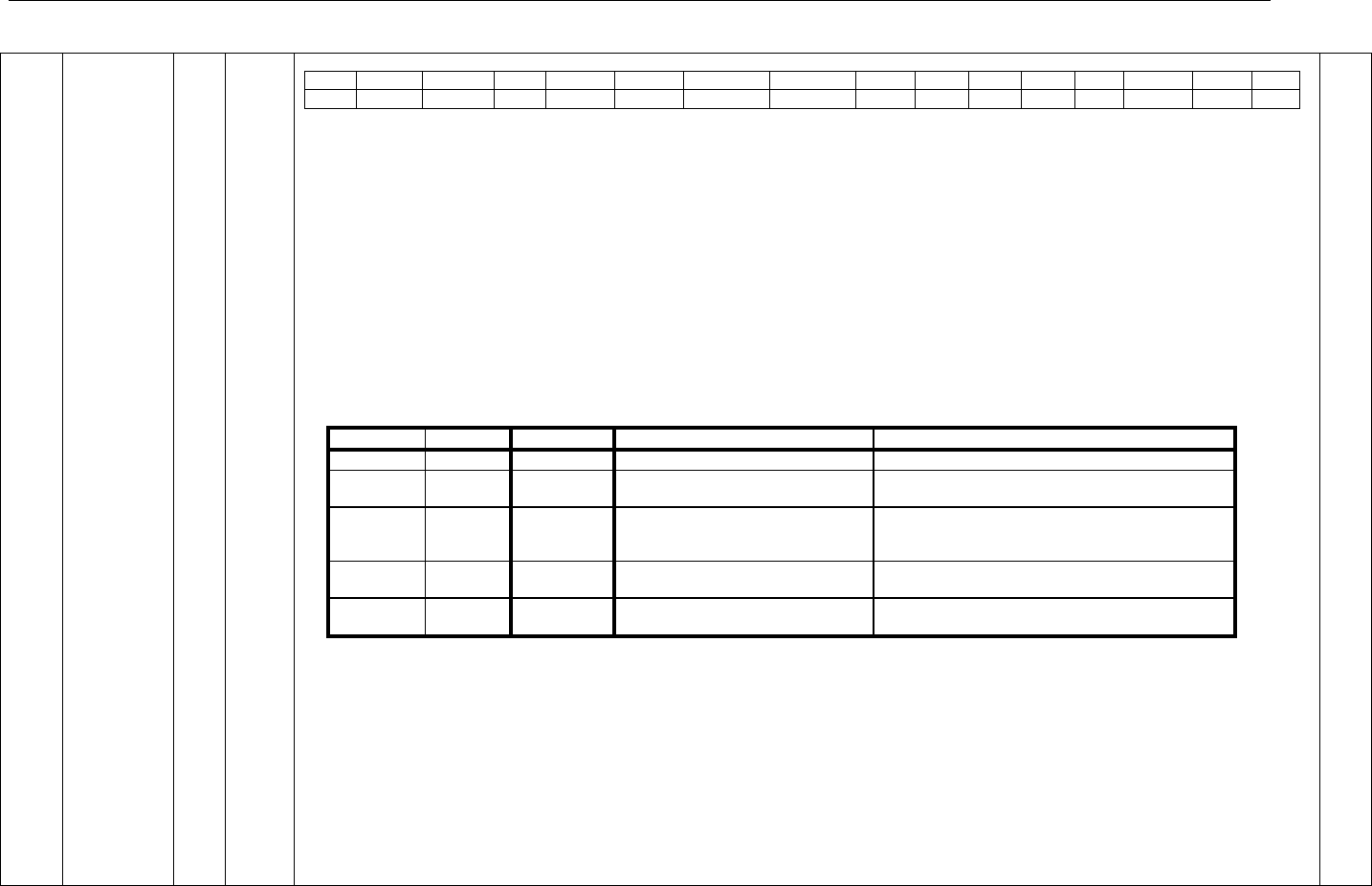
Connect Tech Blue Heat/Net Sync User Manual
Revision 0.01 55
1008
100C
1010
1014
LIFC1,2,3,4
Line Interface
Control
1008= Port 1
100C = Port 2
1010 = Port 3
1014 = Port 4
R/W
D15..0
Control Bits: Read/Write only as a 16 Bit word.
15
14
13
12
11
10
9
8
7
6
5
4
3
2
1
0
X
DCDC
DCDS
ES
FSM
CTSC
CTSM1
CTSM0
RTS
DC
42W
DM
SPT
SP2
SP1
SP0
Important Note: These control bits are transferred to ALL the Line Interface PLD‟s by a serial interface. On each write to any of the 4 control registers, a serial
transfer is started. The transfer takes about 16uS to complete. During this time NO write can occur to any of the 4 registers. A Busy signal is available to indicated
that the transfer is in progress. (See the PLD_STATUS Register, below).
Basic Line Mode Control bits:
SP[2..0] SP508 Line Mode setting bits: See information in SP508 Data sheet. Power-up state=[111].
SPT SP508 Terminator Enable: 0=disable terminator, 1=enable terminator
Duplex Control and RTS Pin Control bits:
DM Duplex Mode selection: 0=Full, 1=Duplex.
42W 4/2 Wire mode selection: 0=2wire (or ½ Duplex), 1=4wire (or Multi-Drop Slave).
DC Duplex Control Source: 0=RTS signal from IUSC, 1=TXComplete signal from IUSC.
RTS RTS Pin Source Selection: 0=RTS signal from IUSC, 1=TXComplete signal from IUSC.
Notes: When Full Duplex mode is selected the “42W” and “DC” bits settings can be changed but are ignored.
Triggered/Gated Transmission Control Bits
CTSM and FSM
FSM
CTSM[1]
CTSM[0]
FSYNC# pin on IUSC
CTS# pin on IUSC
X
0
0
---
Driven from Line Interface CTS signal
0
X
X
Driven directly from Trigger input
signal (inverted)
---
0
0
1
---
CTS pulsed low for 15 clock cycles [1] as follows…
If CTSC=0: clocked by Transmitter clock.
If CTSC=1: clocked by PLD clock (14.66 MHz)
1
0
1
FSYNC Pulsed for 5 or 1 Transmitter
clock cycles [1][2]
CTS pulsed low for 5 or 1 Transmitter clock cycles
[1][2]
X
1
0
---
CTS is turned ON when appropriate TRG bit is ON
(see TRG bits in the PLD_CNTRL register, below)
[1] Whenever the appropriate edge of the Trigger input signal occurs.
[2] The choice of 1 or 5 clock cycles is determined by the previous application of the “First Setup” pulse (Port3 of the IUSC device).
The 5 clock period FSYNC/CTS pulse only occurs once on the first Trigger edge, all following Trigger edges produce a 1 clock FSYNC/CTS pulse.
CTSC CTS Pulse Clock Source: 1=Internal PLD Clock, 0=Transmitter Clock [TxC]
ES Trigger Edge selection: 0=falling edge, 1=rising edge
Gated Reception Control Bits
DCDS IUSC DCD Select: 0=Line Interface DCD signal, 1=Driven by the appropriate TRG bit (in the PLD_CNTL register).
DCDC DCD Clocked: 0=Not clocked, 1=IUSC DCD is synchronized to the falling edge of RxC. (Valid for either of the above DCDS selections).
For Future Use
X Reserved for future use, Set to zero for Writes, zero on Reads
0007

Connect Tech Blue Heat/Net Sync User Manual
56 Revision 0.03
1018
PLD_CNTRL
Control Bits
R/W
D15..0
Control Bits: Read/Write only as a 16 Bit word.
15
14
13
12
11
10
9
8
7
6
5
4
3
2
1
0
IM[3]
IM[2]
IM[1]
IM[0]
TRG[3]
TRG[2]
TRG[1]
TRG[0]
X
X
IABT
SMIE
SR[3]
SR[2]
SR[1]
SR[0]
SR[3..0] IUSC Software Reset: SR[0]=Port1… SR[3]=Port4. Reset is asserted while bit is set to 1. Also, the “Line Interface Control”bits for the given
Port, are set back to their power-up state.
SMIE Serial Master Interrupt Enable: This bit will enable all IUSC interrupts. If the SMIE bit is turned OFF, the Serial interrupt signal to the
Coldfire are turned off, but the Interrupts Status bits remain valid.
IABT IUSC DMA operation Abort: Setting this bit will abort any DMA transfer underway, and is mainly used to abruptly stop autonomous IUSC
operations.
TRG[3..0] TXRX GO: Used to enable the Transmission and Receiver via a hardware signal. These bits cause the CTS and the DCD signal to go ON. (See
the CTSM[] and DCDS bits above).
IM[3..0] Map IUSC Interrupts: to Coldfire Interrupts. IM[p]=0 selects Interrupt-1, IM[p]=1 selects Interrupt-2. Where [p] is the port number (0to3).
Interrupt Information
All the IUSC interrupts are “gated” together and are presented on Coldfire External Interrupt pin #1 or pin #2 (as selected by the IM bits).
All other interrupts (only the Real-Time Clock at this time) are presented to the Coldfire External Interrupt pin #3.
For Future Use
X Reserved for future use, Set to zero for Writes, zero on Reads
0000
101C
PLD_STATUS
Status Bits
Read
Only
D15..0
Control Bits: Read only as a 16 bit word.
15
14
13
12
11
10
9
8
7
6
5
4
3
2
1
0
Busy
PBL
Rev[2]
Rev[1]
Rev[0]
ID[1]
ID[0]
RIS
IS2[3]
IS2[2]
IS2[1]
IS2[0]
IS1[3]
IS1[2]
IS1[1]
IS1[0]
IS1[3..0] Interrupt Status (Interrupt-1): IS1[p]=1 Interrupt active. Where [p] is the port number (0to3).
IS2[3..0] Interrupt Status (Interrupt-2): IS2[p]=1 Interrupt active. Where [p] is the port number (0to3).
RIS Interrupt Status (RTC): 1 Interrupt active.
ID[1..0] PLD ID: Begins at “1” and increments.
Rev[3..0] PLD Revision: Begins at “1” and increments.
PBL Push Button Latch: = 1 whenever the pushbutton was previously pressed (self-cleared at the end of the Read).
Busy LIFC Register Busy: This bit goes high (=1) whenever a Line Interface Control Register is written, and goes low (=0) whenever the register is
available to be used again. (See the LIFC register above).
0900
(initially)
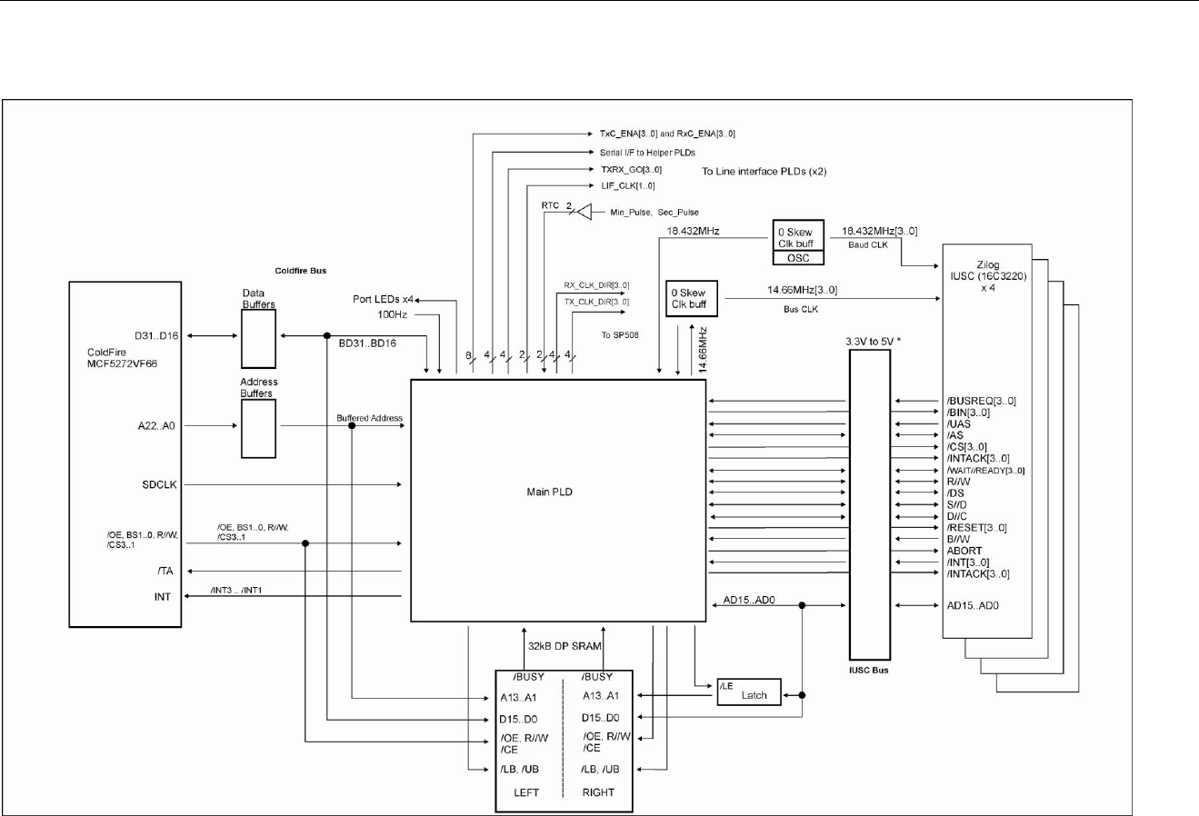
Connect Tech Blue Heat/Net Sync User Manual
Revision 0.01 57
System Block Diagrams
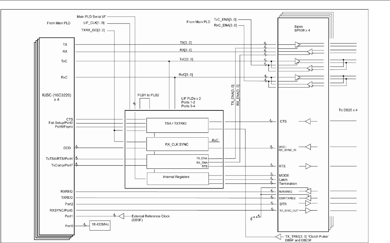
Connect Tech Blue Heat/Net Sync User Manual
58 Revision 0.03

Connect Tech Blue Heat/Net Sync User Manual
Revision 0.01 59
Port Settings, Clock Setup and General Settings
Required [conditions]
Optional [conditions]
(blank) means setting parameter is not required for the mode.
TBD means To be Determined at a later date.
Serial Mode (smode)
BHN_PortSettings
Async
MonoSync
BiSync
Trans-BiSync
HDLC
smode
Required
Required
Required
Required
Required
misc_receiver
TDB
TDB
TDB
TDB
TDB
misc_transmitter
TDB
TDB
TDB
TDB
TDB
r/txclk.ref_freq
Optional [1]
Optional [1]
Optional [1]
Optional [1]
Optional [1]
r/txclk.bps_error
Optional [1]
Optional [1]
Optional [1]
Optional [1]
Optional [1]
r/txclk.bps
Optional [1]
Optional [1]
Optional [1]
Optional [1]
Optional [1]
r/txclk.bps_frac
Optional [1]
Optional [1]
Optional [1]
Optional [1]
Optional [1]
r/txclk.async_div
Required
r/txclk.dpll_div
Optional [2]
Optional [2]
Optional [2]
Optional [2]
r/txclk.ctr_div
Optional [3]
Optional [3]
Optional [3]
Optional [3]
Optional [3]
r/txclk.enc_dec
Required [1]
Required
Required
Required
Required
r/txclk.clk_tree.A
Required
Required
Required
Required
Required
r/txclk.clk_tree.B
Optional [4]
Optional [4]
Optional [4]
Optional [4]
r/txclk.clk_tree.C
Optional [5]
Optional [5]
Optional [5]
Optional [5]
Optional [5]
r/txclk.clk_tree.D
Required
Required
Required
Required
Required
r/txclk.clk_pin
Required
Required
Required
Required
Required
tx_pre_idle.pre_pat
Optional
Optional
Optional
tx_pre_idle.pre_len
Optional
Optional
Optional
tx_pre_idle.tx_idle
Required
Required
Required
Required
Required
line_mode
Required
Required
Required
Required
Required
duplex mode
Required
Required
Required
Required
Required
sync_addr.tx0
Required
Required
Required
sync_addr.tx1
Required
Required
sync_addr.tx_len
Required
Required
Required

Connect Tech Blue Heat/Net Sync User Manual
60 Revision 0.03
Serial Mode (smode)
BHN_PortSettings
Async
MonoSync
BiSync
Trans-BiSync
HDLC
sync_addr.rx0
Required
Required
Required
Required
sync_addr.rx1
Required
Required
Optional
sync_addr.rx_len
Required
Required
Required
sync_addr.strip_sync
Optional
Optional
Optional
dbits.t/rx
Required
Required
Required
Required
Required
tx_frac_stop
Required
parity.t/rx
Required
crc.tx_type
Required
Required
Required
Required
crc.tx_start
Optional [6]
Optional [6]
Optional [6]
Optional [6]
crc.tx_mode
Optional [6]
Optional [6]
Optional [6]
Optional [6]
crc.rx_type
Optional [6]
Optional [6]
Optional [6]
Optional [6]
crc.tx_start
Optional [6]
Optional [6]
Optional [6]
Optional [6]
tx_trig_gate
Required
Required
rx_gate
Required
Required
Required [1]: Must be NRZ or NRZ_INV
Optional [1]: Needed if a clocking source feeds either of the Baud Rate Generators. If the Receiver or Transmitter are clocked directly from certain Line
Interface signals (RxC or TxC setup as inputs) and those Interface signals are setup as outputs, then the indicated parameters are required.
Optional [2]: Required only when the DPLL is part of the clocking tree setup.
Optional [3]: Required only when either Counter (CTR-0 or CTR-1) is directly clocking the Receiver, Transmitter, RxC or TxC signals.
Optional [4]: Only required when the clk_tree.A setting is CLK_DPLL (which is generally only used with Synchronous modes).
Optional [5]: Only required when the clk_tree.A or clk_tree.C setting selects a Baud Rate generator.
Optional [6]: Only required if CRC is enabled.
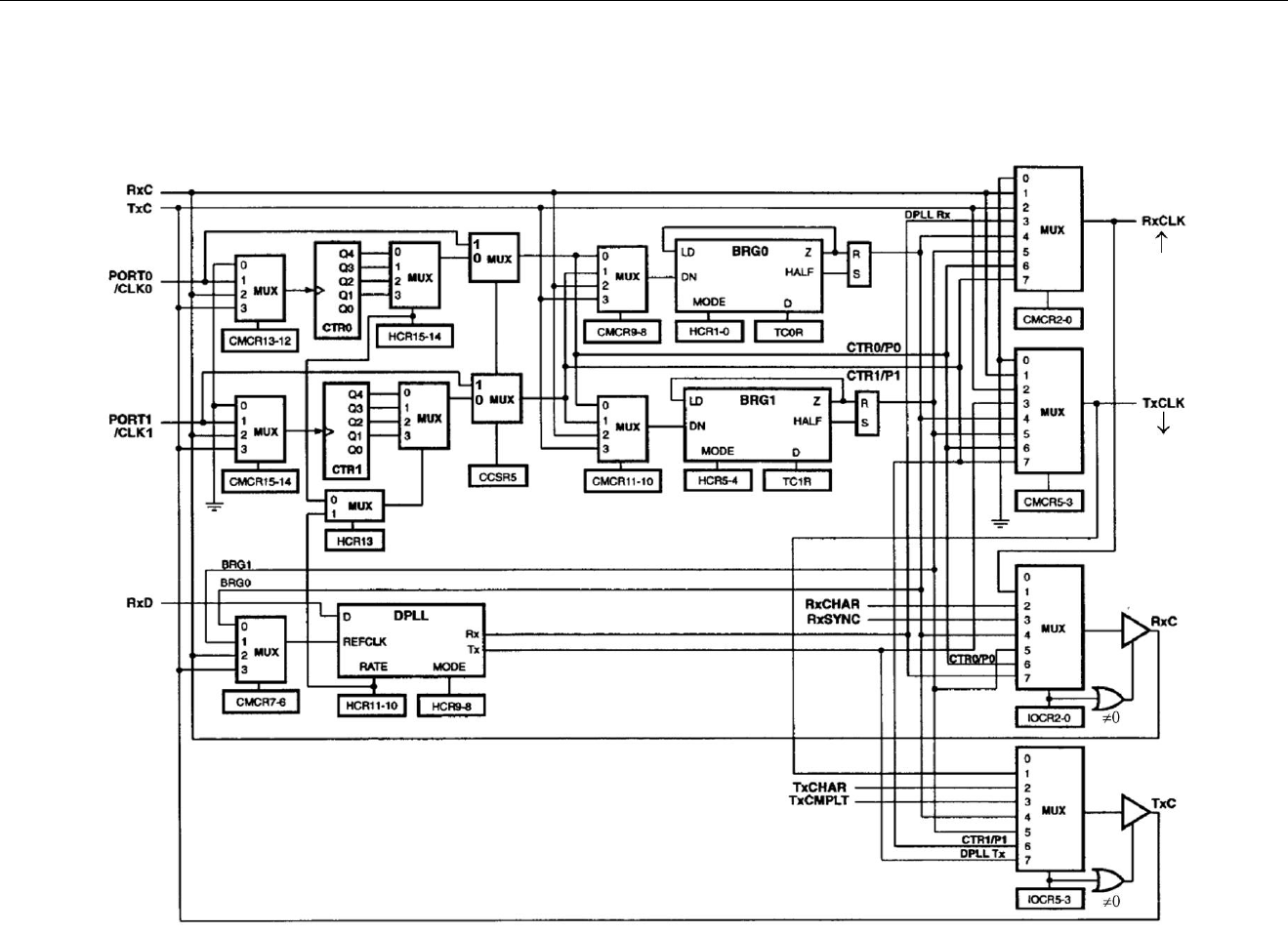
Connect Tech Blue Heat/Net Sync User Manual
Revision 0.01 61
IUSC Clocking Logic:
The following diagram was scanned from the IUSC manual page 4-3 and corrections have been made. Do not use the diagram from the IUSC manual, use the
corrected version we have provided below.

Connect Tech Blue Heat/Net Sync User Manual
62 Revision 0.01 62
Appendix
Blue Heat/Net Sync Specifications
Operating Environment
4 port model: 0ºC to 60ºC (32ºF to 158ºF)
Communications
Baud Rates:
Synchronous: Up to 9.216 Mbps with internal reference clock, up to 10 Mbps with
external reference clock.
Asynchronous: 230.4 Kbps
Custom baud rates are also available. Please contact our sales@connecttech.com department for
information.
ESD Protection
15kV
Power
Rev A models: 5V (2.5A) power input using a DC barrel or Phoenix screw terminal connector.
Rev B models: 5V (2.5A) to 26V (450mA) power input using a DC barrel or Phoenix screw
terminal connector.
Connectors
Serial I/O: DB25 Female
Auxiliary I/O: DB9 Female
DC Power: Standard DC Power connector or Phoenix screw terminal
Ethernet: RJ45
Dimensions
Blue Heat/Net Sync
Length: 133 cm/5.24 inches
Width: 244 cm/9.61 inches
Height: 43 cm/4.69 inches
Compliant with 1U 19” rack specifications
Cable and Power Supply Options
Blue Heat/Net Sync products are available in a variety of configurations. Please contact the
Connect Tech sales@connnecttech.com department for more information on your model
number.

Connect Tech Blue Heat/Net Sync User Manual
Revision 0.01 63 63
Protocol Descriptions
The Blue Heat/Net Sync supports a variety of protocols. The following is a brief explanation of
each and how they are implemented.
ARP
Address Resolution Protocol, a method used to find a unit‟s Ethernet MAC address from its
Internet address.
BOOTP
Bootstrap Protocol, a protocol that allows a unit to boot from the network instead of using
information stored on the Blue Heat/Net Sync (typically in Flash memory).
DHCP
Dynamic Host Configuration Protocol, a protocol that provides a means to dynamically
allocate IP addresses to computers on a local area network. The system administrator assigns
a range of IP addresses to DHCP and each client device on the Local Area Network requests
an IP address from the DHCP server. The request and grant process uses a lease concept with
a controllable time period. The Blue Heat/Net Sync offers this as a configurable option; it
can either be turned on or the user can set a fixed IP on the unit.
HTTP
HyperText Transfer Protocol, a standardized Protocol that Web Browsers use to connect to
web pages. It is used to provide web based configuration tools on the Blue Heat/Net.
IP Internet Protocol, a common addressing scheme for modern networks. Used in conjunction
with TCP to form TCP/IP (see below)
RARP
Reverse Address Resolution Protocol, a method to find a unit‟s Internet address from a MAC
or Ethernet address.
TCP
Transmission Control Protocol, a lossless protocol, requiring a handshake to insure that data
is not lost during transmission. Used in TCP/IP to form the main data transfer pathway
between Blue Heat/Net Sync units and the host computer.
Telnet
A terminal-protocol that can be run over TCP/IP to connect to a remote unit. It is one of the
methods used to configure the Blue Heat/Net Sync unit.
TFTP
Trivial File Transfer Protocol, a protocol used to download firmware to the Blue Heat/Net.
UDP
User Datagram Protocol, a protocol used when handshake is not critical. It is used by TFTP
(see above) and for auto discovery of the units.

Connect Tech Blue Heat/Net Sync User Manual
64 Revision 0.03
Pinouts
DB-25 Female Pinouts
DB25F
Line Mode
Pin #
Signal Name
V.28 in brackets
V.35
EIA-530
RS232
(V.28)
EIA-530A
X.21
(V.11)
14
TX+
V.35 [4]
V.11
Hi-Z
V.11
V.11
2
TX- (TX)
V.35 [4]
V.11
V.28
V.11
V.11
16
RX+
V.35 [4]
V.11 [1]
Hi-Z
V.11 [1]
V.11 [1]
3
RX- (RX)
V.35 [4]
V.11 [1]
V.28
V.11 [1]
V.11 [1]
23
DTR+
Hi-Z
V.11
Hi-Z
Hi-Z
V.11
20
DTR- (DTR)
V.28
V.11
V.28
V.10
V.11
19
RTS+
Hi-Z
V.11
Hi-Z
V.11
V.11
4
RTS- (RTS)
V.28
V.11
V.28
V.11
V.11
13
CTS+
Hi-Z
V.11
Hi-Z
V.11
V.11
5
CTS- (CTS)
V.28
V.11
V.28
V.11
V.11
21
DSR+
Hi-Z
V.11
Hi-Z
Hi-Z
V.11
6
DSR- (DSR)
V.28
V.11
V.28
V.10
V.11
10
DCD/RX_SYNC_IN+ [5]
Hi-Z
V.11
Hi-Z
V.11
V.11
8
DCD/RX_SYNC_IN- [5] (DCD)
V.28
V.11
V.28
V.11
V.11
11
TXC+ [2]
V.35 [4]
V.11 [2]
Hi-Z
V.11 [2]
V.11 [2]
24
TXC- [2] (TXC)
V.35 [4]
V.11 [2]
V.28
V.11 [2]
V.11 [2]
9
RXC+ [2]
V.35 [4]
V.11 [2]
Hi-Z
V.11 [2]
V.11 [2]
17
RXC- [2] (RXC)
V.35 [4]
V.11 [2]
V.28
V.11 [2]
V.11 [2]
15
(TXC)
NC
NC
V.28
NC
NC
12
RX_SYNC_OUT- [6]
V.28
NC
V.28
NC
NC
22
RI (RI)
V.28
V.10
V.28
V.10
Hi-Z
18
TX_TRIGGER
[7]
[7]
[7]
[7]
[7]
7, 1
SR
SR
SR
SR
SR
SR
[1] 120 ohm resistor applied between the (+) and (-) signals.
[2] 120 ohm resistor applied between the (+) and (-) signals when the signal is an input.
[3] This signal can be programmed to be a input or an output.
[4] V.35 Termination Network is applied between (+) and (-) signals.
[5] External Sync input used to enable or disable the receiver. This pin is used in external Sync
mode. A logical low will enable the receiver.
[6] This output indicates that the Receiver has received a RX Sync character. It could also be used
as a general purpose I/O signal.
[7] See the table titled Auxiliary Connector under TX_TRIGGER for details.
NC means DO NOT CONNECT.
Signal Description:
Mode
Equivalent Standard
Electrical
Typical Voltage
V.10
RS-423
Single ended
+/- 5VDC
V.11
RS-422 / RS485
Differential
1.5VDC to 4.5VDC
V.28
RS-232
Single ended
+/-12VDC
V.35
V.35
Differential
550mVDC
Table 9: DB-25 Female Pinouts
Connect Tech Blue Heat/Net Sync User Manual
Revision 0.01 65 65
DB-9 Female Pinouts
DB9F
Pin
Signal Name [1]
Functional
Notes
1
RTC_Clear
Clears and holds the seconds count of the Real Time Clock at
00.
[3], [6]
2
RTC_Seconds
Provides the external time base for the Real Time Clock.
Internal time base is 1Hz
[3], [5]
3
GND
Signal reference for all signals
4
EXT_REF_CLK
0-20MHz clock input
[2]
5
GND
Signal reference for all signals
6
TX_TRIGGER_P1
Transmission trigger for port 1
[3], [4], [5]
7
TX_TRIGGER_P2
Transmission trigger for port 2
[3], [4], [5]
8
TX_TRIGGER_P3
Transmission trigger for port 3
[3], [4], [5]
9
TX_TRIGGER_P4
Transmission trigger for port 4
[3], [4], [5]
[1] All signals are inputs.
[2] Electrical properties for External Reference clock input:
+/- (1-10)Vpp AC sine wave
+/- (3.3-10Vpp square wave.
10-20MHz Frequency range.
Capacitive coupled input.
Must be referenced to GND pin.
TTL compatible. For example 0-3.3V or 0-5V will work.
[3] Electrical properties:
+/- (3.3- 10)Vpp pulse.
Minimum pulse width is 100ns seconds.
Capacitive coupled input.
Must be referenced to GND pin.
TTL compatible. For example 0-3.3V or 0-5V will work.
[4] Used for Asynchronous transmissions. When the mode is enabled, the Blue Heat/Net Sync will
transmit exactly one byte of data when the TX_TRIGGER input changes state. These same
signals are available on the individual DB25 port connectors.
[5] The input is edge sensitive and can be configured for negative or positive edge sensitivity.
[6] The input is level sensitive and can be configured for 1 or 0 level sensitivity.
Table 10: DB-9 Female Pinouts
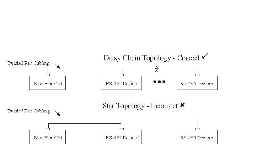
Connect Tech Blue Heat/Net Sync User Manual
66 Revision 0.03
Multi-drop Communications Using V.11 / RS422/RS485 Line Modes
When wiring multi-drop RS-485 networks, it is necessary to wire the devices in a “Daisy
Chain”, they must not be wired with a “Star” topology, see diagram.
Rack Mount Option:
Blue Heat/Net Sync can be rack mounted using the option rack mount kit part number MSG029.

Connect Tech Blue Heat/Net Sync User Manual
Revision 0.01 67 67
Default Settings
Network Settings
Blue Heat/Net Sync IP address 192.168.42.1
Server IP address 0.0.0.0 (used for firmware downloads)
Gateway IP address 0.0.0.0
Subnet Mask 255.255.255.0
Broadcast IP address 255.255.255.255 (used by the bootp process)
Domain Name Server IP address: 0.0.0.0 (used for firmware downloads)
Domain Name blueheat.net
Host Name BHNssssssss (where ssssssss is the BHN serial number)
TCP Port 49152 (0xC000)
DNS IP 0.0.0.0
Boot Settings
Default enabled:
Boot from Flash
Default disabled:
use BOOTP
use TFTP
Delay: 30 (seconds)
SCM Operation Settings
Password: password
Password Prompting: enabled
Loader Filename: BHNloader_vvv.gz
(where vvv is the version number of the Loader, current at the time the unit was manufactured).
Line Setting: See Getting Access to the SCM section.

Connect Tech Blue Heat/Net Sync User Manual
68 Revision 0.03
Common Configuration Setups
Static IP Setup
In some networking environments it is best to have the IP address set to a fixed value. The
advantage is that since it is fixed, connecting to it can be a lot simpler.
Static IP is often the best choice if you are trying to connect via WAN or through a Firewall. It
can be difficult to resolve the Blue Heat/Net Sync‟s IP address if you use DHCP in this instance.
The default configuration is a static IP of 192.168.42.1. In most cases this will not be the address
you want to use in your network. You can change it using two different methods:
Serial Configuration Manager (SCM)
A direct serial connection to on of the serial ports on the Blue Heat/Net Sync.
Or
Web Configuration Manager (WCM)
Using a web browser like Internet Explorer to connect to the unit.
Refer to the manual sections for specific details on using the SCM and WCM.
Example:
You want to configure a static IP on a Blue Heat/Net Sync of 198.182.196.15. The network‟s
server is at 198.182.196.1 and the gateway is 198.182.196.2. The subnet mask is 255.255.255.0.
Using SCM
Log onto the Blue Heat/Net Sync. There is no login necessary if using SCM. The default
password for the SCM is password.
Enter net net=198.182.196.0. This will set 198.182.196.0 to the server, gateway and the unit‟s IP
in one step.
Enter net my_ip=15. This will set the unit‟s IP to 198.182.196.15.
Enter net server_ip=1. This will set the server IP to 198.182.196.1.
Enter net gateway_ip=2. This will set the gateway IP to 198.182.196.2.
Enter net subnetmask=255.255.255.0. This will set the subnet mask.
Enter net dns_ip=3. This will set the DNS IP to 198.182.196.3
Enter net dhcp=no. This will turn off DHCP on the unit.
Enter save. This will save the configuration set above to flash memory.
Enter exit. The unit will reboot using the new settings.
Using WCM
Connect to the Blue Heat/Net Sync using a web browser by entering the current IP of the unit in
the address.
Log on by supplying the username and password. The default login is wcm and the default
password is password.
Select the Blue Heat/Net Sync Settings page and fill in the server IP, Blue Heat/Net Sync IP,
Gateway IP, DNS IP and subnet mask as defined above.
Ensure the Use DHCP option is set to no
Click on the Save to Flash button to store the changes.

Connect Tech Blue Heat/Net Sync User Manual
Revision 0.01 69 69
DHCP Setup
In many modern networks IP numbers are not static but are automatically assigned by a DHCP
server and can change over time or on each power up.
DHCP must be enabled on the Blue Heat/Net Sync because it is shipped to use a default static IP
(192.168.42.1)
Using SCM
Log onto the Blue Heat/Net Sync. The SCM does not require a login. The default password for
the SCM is password.
Enter net dhcp=yes. This will turn on DHCP on the unit.
Enter net dns_ip=3. This will set the DNS IP to 198.182.196.3
Enter save. This will save the configuration we just set to flash memory.
Enter exit. The unit will reboot using the new settings.
How the Blue Heat/Net Sync Boots Up
Each time the Blue Heat/Net Sync is powered-up or rebooted with an appropriate command, a
certain sequence of software execution occurs.
The Booter runs from flash memory first. Its job is to perform the following:
Setup the embedded processor
Validate at least one of the redundant Loaders (via a CRC check).
Load a validated Loader into RAM memory.
Run the Loader.
If the Booter discovers that both Loader programs are defective (erased or faulty CRC
calculation), an error code is displayed on the LEDs of the Blue Heat/Net Sync.
The Loader runs from RAM memory. Its job is to perform the following:
o Update any required CDS items.
o Determine if the SCM application will be entered. This is accomplished by
scanning the designated serial ports, for a period of time, to determine if a
correct password is entered. If the password is found the SCM application will
be entered. (see the SCM Command Reference command for details of these
settings).
o Locate, load and run an Operating System (uClinux). (As shown in the
following boot-up flow chart).
o Run the main Operating System (uClinux).
o Operating System launches port personality default ctid
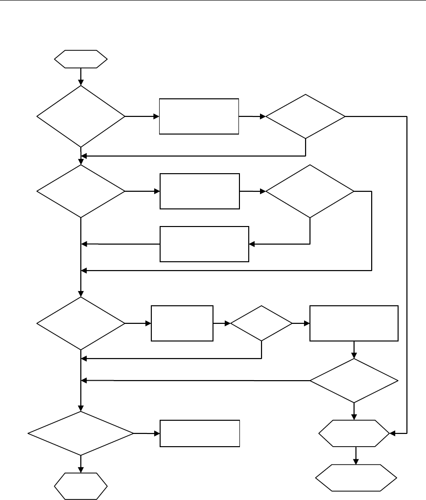
Connect Tech Blue Heat/Net Sync User Manual
70 Revision 0.03
Bootup Sequence
Figure 30: Bootup Sequence
Boot from
Flash
Enabled?
Decompress
uClinux from Flash
to SDRAM
Bootp
Enabled?
Y
Y
N
Obtain boot
information from
Bootp Server
Decompress
OK
N
Server
Responds
Update CDS (RAM copy)
Information
(filename & IP address)
Y
TFTP
Enabled?
N
N
Attempt TFTP
Download
Y
Start
Enter
SCM
Success
All Boot Modes
Disabled
N
Y
Display Error on
LEDs
Decompress
Downloaded uClinux
into SDRAM
Decompress
OK
Y
N
Run
uClinux
Y
Y
N
N
Y
Boot Port
Personality
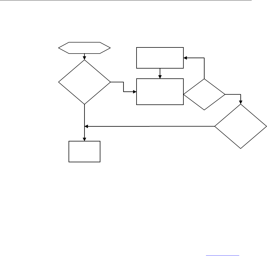
Connect Tech Blue Heat/Net Sync User Manual
Revision 0.01 71 71
Flowchart of Special Operations Mode using the reset button
Figure 31: Bootup Sequence via Reset Button
Asynchronous Communications Tutorial
The Blue Heat/Net Sync features four synchronous/asynchronous serial communication ports.
Asynchronous communication is a simple, cost effective means of terminal serial
communication. For this reason, it is widely used for communications on personal computers,
bar codes readers, printers, terminals and much more. The following documention represents a
basic tutorial for asynchronous communications. For a tutorial on synchronous communications,
please refer to the Z16C32 IUSC User’s Manual (DOC ID DC8292) on the Zilog website.
In asynchronous serial communication, the electrical interface is held in the idle position
between characters, also referred to as “mark”. A change in signal level (known as space level)
indicates the start of transmission of a character. The receiver recognizes this change as a “start
bit”. Once the start bit has been sent, the transmitter sends the actual data bits. In typical
asynchronous communications there may be 5, 6, 7, or 8 data bits, depending on the application.
Both the receiver and the transmitter must be set to the same number of data bits, baud rate and
stop bits. Stop bits can be 1, 1.5, or 2 bit periods in length. When the transmitter has sent all the
data bits, it sends a stop bit. This stop bit signals to the receiver that the data has finished
transmission. The stop bit is the same state as the idle or mark state.
Reset
Button
Held
Power Up
Continue
Booting
Show
Selection State
On Port LEDs
Reset
Button
Increment
Selection
Pressed
Held
Wait for
Button
Release
Yes
No

Connect Tech Blue Heat/Net Sync User Manual
72 Revision 0.03
Figure 32: Typical Asynchronous Date Frame
Serial Line Interface Tutorial
RS-232 Line Interface:
RS-232 is the simplest, least expensive line interface standard, the Sipex tranceivers used on the
Blue Heat/Net Sync refer to RS232 as V.28 mode. It is also referred to as EIA232 and TIA/EIA-
232. The RS-232 specification signals levels of +3V to +15V for a logic 0 or Space, and -3V to -
15V for a logic 1 or Mark. The Blue Heat/Net Sync has RS-232 signal levels with a typical
range of +/- 8 Volts. The maximum cable length you can use with RS-232 is dependant on a
number of factors including:
Baud rate: The higher the baud rate, the shorter the cable length must be.
Cable quality: Quality largely refers to the capacitance of the cable. A higher capacitance
(usually specified as pF or pico Farads per foot) dictates a lower baud rate, and a shorter
maximum length. Low capacitance computer cables for RS-232 applications are available from
all wire and cable suppliers.
You can usually operate with cable lengths of up to 100 feet (30 m) at baud rates up to 115.2
Kbps using low capacitance cable. For higher baud rates such as 230.4 Kbps and up, we
recommend keeping the cable lengths to within 25 feet (7.6 m).
The TIA/EIA232 specification specifies two connectors: the DB-25 and the DB-9. Each of these
connectors has a standardized pinout. Refer to the Pinouts section of the manual for the DB-25
RS-232 (V28) pinout.
Differential Line Interfaces:
The Blue Heat/Net Sync features Sipex SP508 multi-protocol transceivers. These transceivers
features the following differential line standards.
V.11: A differential line interface with signal levels compatible with RS-485 and RS-422.
V.10: A single ended line interface that can be wired such that it will have some of the noise
cancelling features of RS485 (V.11). This interface is also called RS-423.
V.35: A differential line interface that operates in a current loop. The electrical levels are about
+/- 550mV.
RS485/RS422/V.11 Details
V.11, RS-485, or TIA/EIA485, is a differential line interface standard capable of high baud rates
over long cables. The Sipex tranceivers used on the Blue Heat/Net Sync refer to RS-485 as V.11
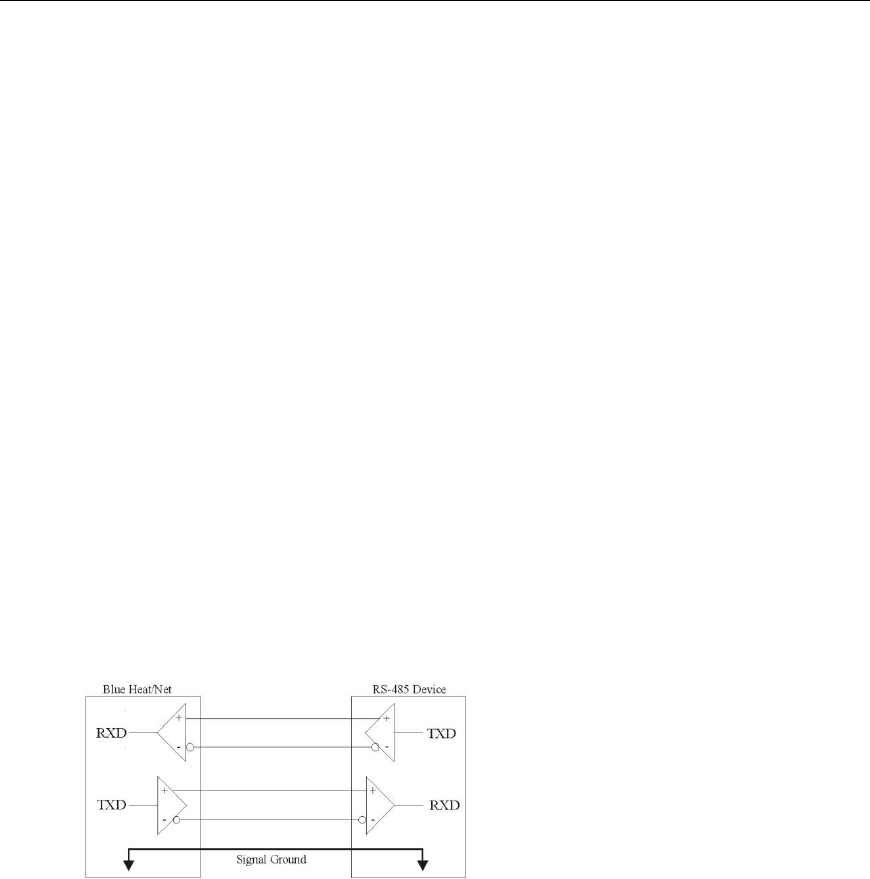
Connect Tech Blue Heat/Net Sync User Manual
Revision 0.01 73 73
mode RS-485 is fully compatible with RS-422; which is considered a subset of RS-485.
The use of differential transmitters and receivers ensures RS-485 communications are reliable
and robust. This means two wires are used to transmit or receive a signal. One wire carries the
true or non-inverted signal; the other wire carries the inverted signal. The non-inverted signal is
labelled with a (+) and the inverted is labelled with a (-). The differential communication refers
to the (+) as “TXB” and the (-) as “TXA”.
Any noise injected into the wires is cancelled at the receiver, leaving only the original,
undistorted data signal. Twisted pair cables are always used in RS-485, this ensures that the
communications are robust and as error free as possible. RS-485 signal levels are between 0 and
5 Volts, the differential voltage can be as little as 200mV.
Differential can operate in three different modes: a 4-wire full duplex interface, 4-wire multi-
drop full duplex interface and a 2-wire half duplex interface. A full duplex (bi-directional)
differential communication interface requires at least four wires, two for transmit and two for
receive. A half duplex interface only requires two wires, this provides a cost effective cabling
solution.
Multi-drop is a great feature of RS-485. Multiple RS-485 devices can be bussed together in a
daisy chain type fashion to create a network. Up to 32 devices may be connected together on the
same network. In multi-drop networks, one of the devices (usually the computer) is designated
as the master, and all the other devices are designated as slaves. All communication is initiated
by the master. The master and slave designations are established by your communications
application.
Basic 4-Wire, Full Duplex Communications:
In a 4-wire RS-485 network, two devices are connected together, for example your Blue
Heat/Net Sync RS-485 port and an RS-485 device.
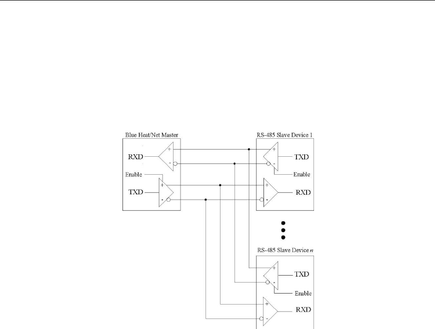
Connect Tech Blue Heat/Net Sync User Manual
74 Revision 0.03
Multi-drop 4-Wire, Full Duplex Communications:
In a multi-drop 4-wire differntial network, two to 32 devices are connected together. Note that
each RS-485 receiver counts as a device or “load”. In this multi-drop mode of communication, a
master slave protocol must be enforced, that is, all communication is initiated by the master, in
this case a Blue Heat/Net Sync. The communication is “full duplex”, meaning that receive and
transmit traffic occur on different pairs of wires. The Blue Heat/Net Sync can receive and
transmit data from/to a device at the same time.
Basic - Wire, Half Duplex Multi-drop Connection:
In a 2-wire differntial network, two to 32 devices are connected together. Note that each receiver
counts as a device or “load”. In this multi-drop mode of communication a master slave protocol
must be enforced, that is, all communication is initiated by the master, in this case a Blue
Heat/Net Sync. The communication is “half duplex”, meaning that receive and transmit traffic
occur on the same wire. The Blue Heat/Net Sync and devices can not receive data and transmit
data at the same time.
Note that the Receiver +/- and the Transmitter +/- signals are connected together. This is
performed at the DB-9 connectors. All communication between devices occurs over a single pair
of wires; this can lower the cost of wiring your network.
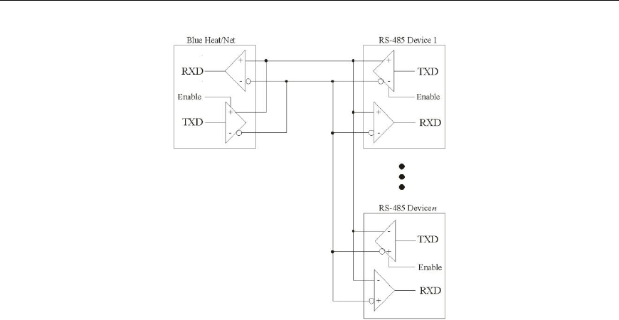
Connect Tech Blue Heat/Net Sync User Manual
Revision 0.01 75 75
Bus Contention on Differential Multi-drop Networks:
Bus contention occurs when two or more devices enabled on a bus attempt to run the bus to
opposite logic values. From the diagram above, we can see that there are multiple differential
transmitters (TXD) on the bus. To avoid the bus contention problem, the differential transmitter
features a tri-state, or high impedance mode controlled by an input pin (enable). Software and
hardware in the Blue Heat/Net Sync and the differential devices will always place its transmitter
into the high impedance mode when not transmitting. This feature is managed by the Blue
Heat/Net Sync and is fully transparent to your application.
For example, in a multi-drop network, the differential transmitter is enabled prior to the master
initiating transmission. When transmission is complete, the transmitter is placed in high
impedance mode. Each slave will receive that transmission from the master. (A protocol must be
in place to address, or select, the desired slave device, but that discussion is beyond the
intentions of this tutorial, and is entirely application dependent). When the slave device has
received the data, it will respond by enabling its transmitter and transmitting data onto the bus,
then placing its transmitter into high impedance mode, just as the master did.

Connect Tech Blue Heat/Net Sync User Manual
76 Revision 0.03
Termination Resistors in Differential Networks
Termination Resistors in Differential Networks:
Differential networks often benefit from the installation of termination resistors. Termination is
rarely required for lower baud rates, for example 9600 baud or less. However, differential
networks are transmission lines, and can suffer from the electrical effects of ringing, or
undershoot and overshoot, all of which can cause data errors, especially at higher baud rates, like
115.2 Kbps. Termination resistors should always be installed at the extreme ends of the network,
as close to the differential transceiver circuits as possible, as outlined in the diagram below.
NOTE: The Blue Heat/Net Sync features software
selectable termination.
