Connected AG21 GPRS GPS Tracker User Manual
Connected Holdings LLC GPRS GPS Tracker
UserManual.wiki
>
Connected
>
AG21 User Manual
User manual
Navigation menu
Upload a User Manual
Namespaces
Wiki Guide
HTML
PDF
Info
Views
User Manual
Discussion / Help
Navigation
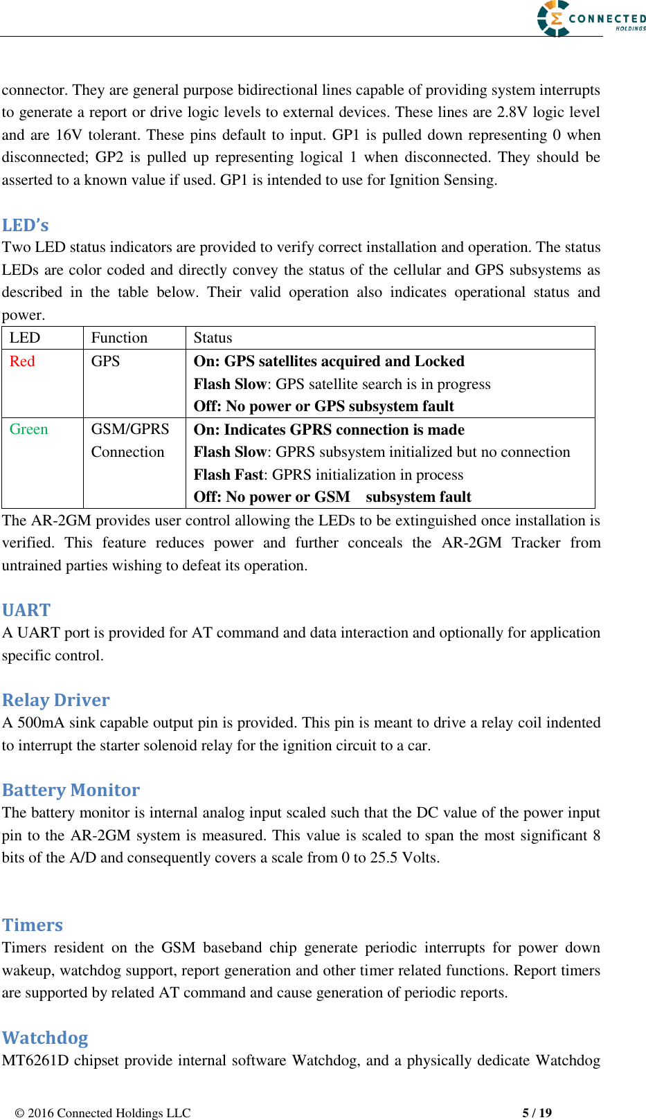
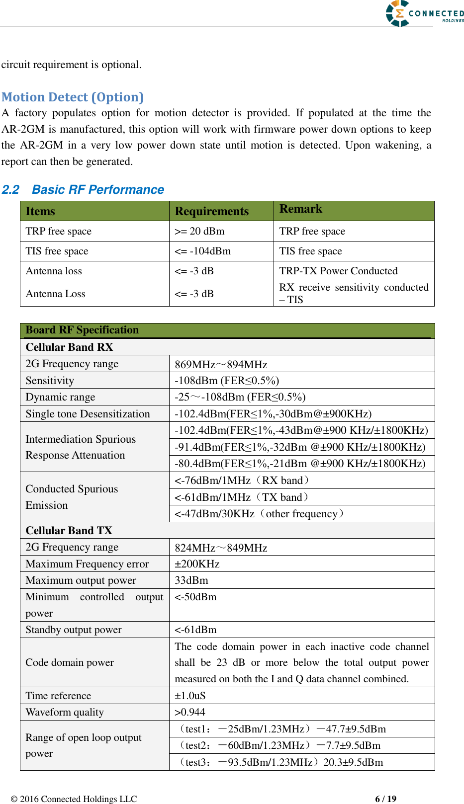
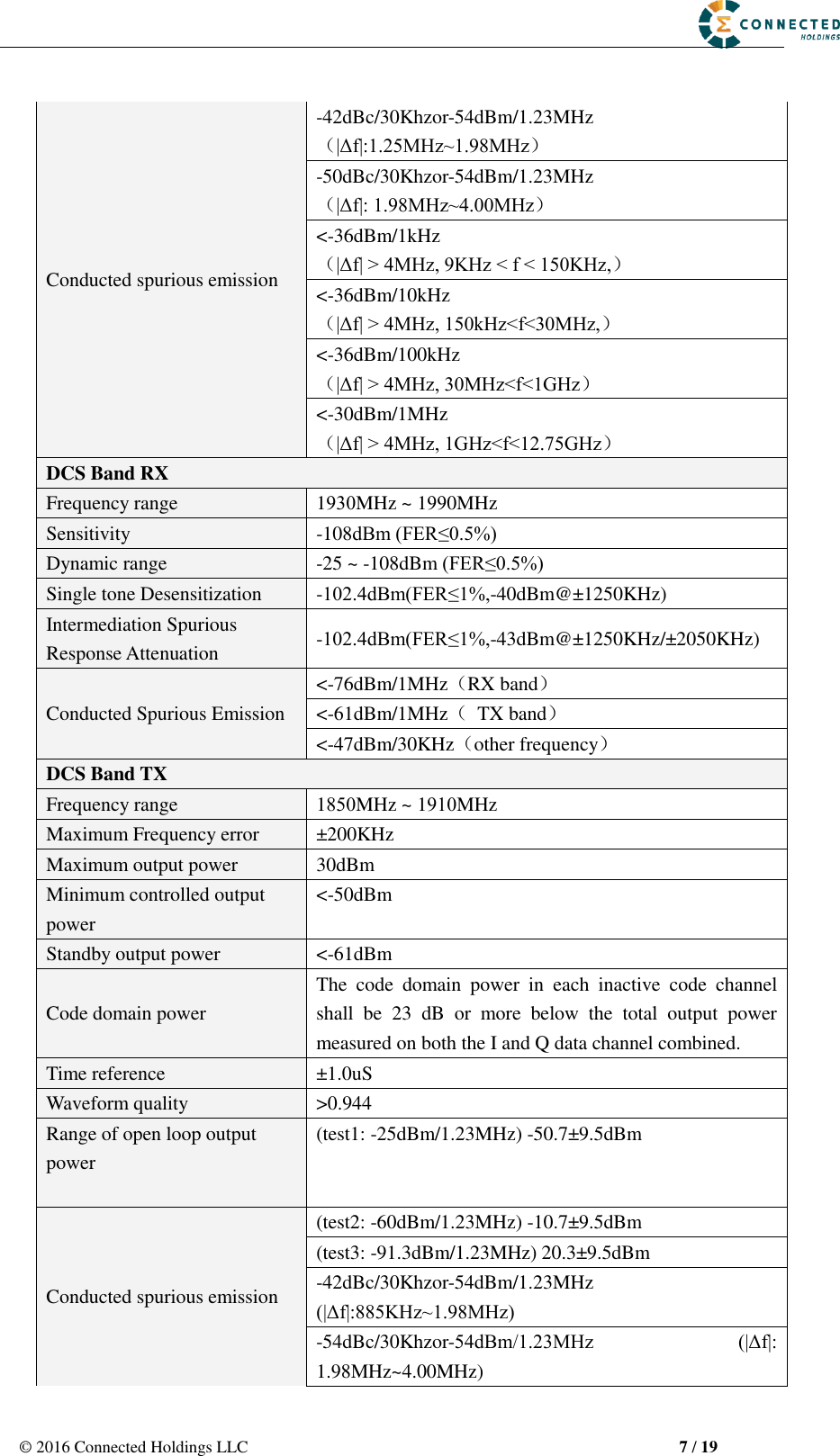
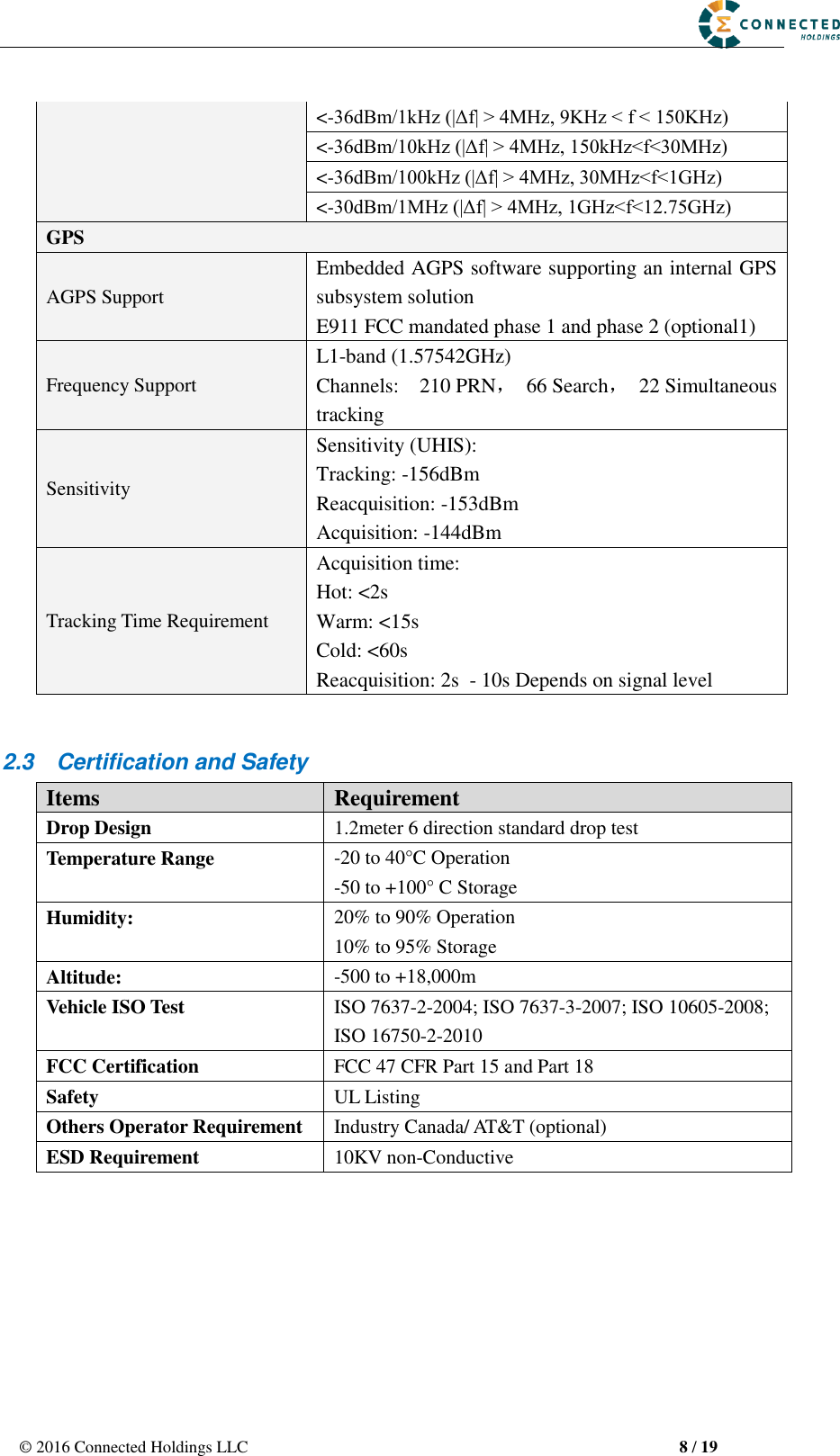
![© 2016 Connected Holdings LLC 4 / 19 2 Hardware Design 2.1 Basic Hardware Items Requirement Baseband Chipset MT6261D RF 2G Transceiver AP6682 Air Interface Support for Class 12 GPRS, GPS Frequency 2G band support : 850MHz &1.9GHz Support for 12 class GPRSAntenna Internal Antenna [850M&1900M]GPS Antenna Dedicate high performance ceramic antenna UIM requirement No-UIM mode, GSM card connector optional Interface UART TX Battery Monitor UART RX Build in battery manager 12V DC Input(1A current) Relay Drive (12V Output ,500mA current) GPIO1 GPIO2 internal analog input scaled (Optional) Supported Dedicate Timers No Watchdog Supported Motion Detect Optional(GPS/Sensor) LED 2 LED Supported 2 LEDs(one is RED,one is Green) Battery Built in battery(80MAH Lion) Working Time 4 hours Power switch No Power Cable color 8 colors Power Cable connector type 8 pin Power Consumption < 5Watts The AR-2GM provides support for specialized hardware features through extended AT commands. The features supported include the following. GPS The major functionality of the GPS module is to compute the correlation results between the incoming signal and the selected PRN code based on certain Carrier Doppler Frequency, Code Doppler Frequency, code phase, carrier phase, and the particular satellite the module is tracking or acquiring. GPIO Two GPIO pins, GP1 and GP2, are presented to the external environment on the main](https://usermanual.wiki/Connected/AG21/User-Guide-3104674-Page-4.png)