Connected AG21 GPRS GPS Tracker User Manual
Connected Holdings LLC GPRS GPS Tracker
User manual

© 2016 Connected Holdings LLC 1 / 19
User Manual
For the
AR-2GM
Vehicle Tracking Device
April 20, 2016
R1.1
Author
Revision
Changes
Date
Hao
1.1
Initial version
2016-07-28
The information presented in this document is strictly confidential and contains trade secrets
and other confidential information that are the exclusive property of Connected Holdings

© 2016 Connected Holdings LLC 2 / 19
Contents
1 Introduction 3
2 Hardware Design 4
2.1 Basic Hardware 5
2.2 Basic RF Performance 6
2.3 Certification and Safety 9
3 Software Features 10
3.1 Basic Software 10
3.2 Remote Update 10
3.3 Power Modes 10
3.4 AT Command 11
Event Setting Commands 11
Action Commands 12
File Update Commands 12
Periodic Action Commands (with Events) 13
Configuration Commands 13
Communication related settings 13
Protocol related settings 13
Drive Trip related settings 13
Peripheral related settings 13
Maintenance report settings 14
Miscellaneous settings 14
Information Commands 14
Configuration reading commands 14
Information commands 14
3.5 Report 15
Report Queuing 15
Ack’ed Mode 15
Event Report Format 15
3.6 Reset 16
3.6.1 Context Preservation 16
3.7 Startup Banner 16
4 Test Method 17
4.1 Hardware 17
4.2 Software Test 17
Mechanical Structure(mm) 18
FCC Statement 19
RF Exposure Warning Statements: 19
IC STATEMENT 19
© 2016 Connected Holdings LLC 3 / 19
1 Introduction
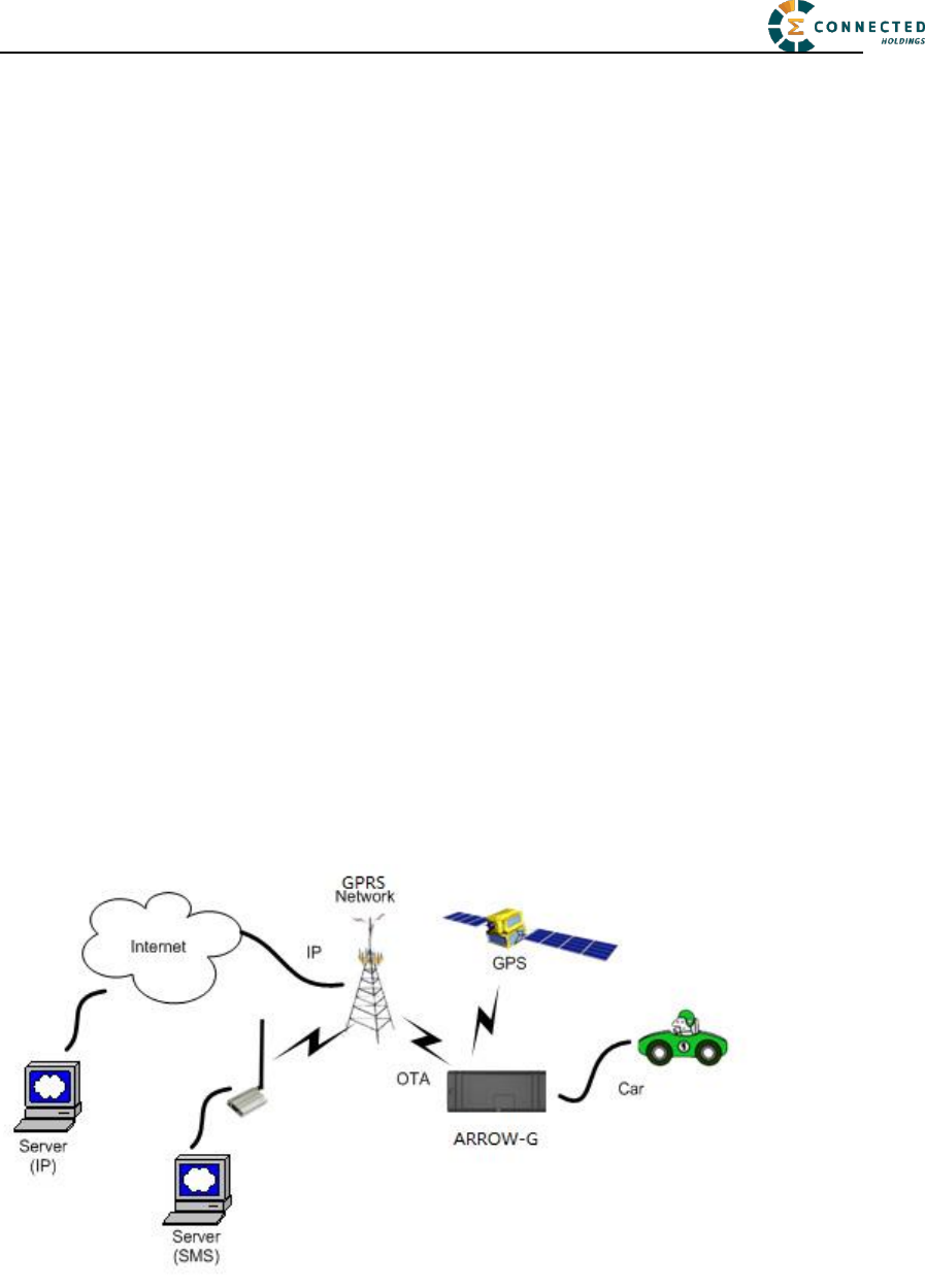
The AR-2GM is a self-Contained vehicle tracking device that combines GPS location with
GSM/GPRS connectivity.
The AR-2GM appears to a user or a server application as a single endpoint device. It can be
queried, updated and configured either through a serial connection, or an over the air GPRS
IP connection, or through SMS messaging. The AR-2GM presents itself over these
connections as an enhanced cellular modem with attached functional elements. These
elements include:
GPS location engine
2 General Purpose Bidirectional I/O (GPIO) pins
1 Relay drive pin output
Serial UART port
Input voltage monitor (optional)
Timers
Watchdog lockup protection (Dedicated watchdog circuit is optional)
Factory load option for motion detection
Access to these elements and general purpose interfaces is done through an extended AT
command set as defined herein.
Application scene:
This product will be designed based on the 2G wireless data/MT6261 Baseband chipset,
which includes GPS functionality, ARM CPU and GPRS protocol. This baseband internal
connection 4M serial flash, GSM 850M/1900M RF Transceiver &GPS receiver, and RF Front
end circuit.
The device will use one dual band antenna(GSM850&PCS1900)and one dedicate
GPS antenna.

© 2016 Connected Holdings LLC 4 / 19
2 Hardware Design
2.1 Basic Hardware
Items
Requirement
Baseband Chipset
MT6261D
RF 2G Transceiver
AP6682
Air Interface
Support for Class 12 GPRS, GPS
Frequency
2G band support : 850MHz &
1.9GHz Support for 12 class GPRS
Antenna
Internal Antenna [850M&1900M]
GPS Antenna
Dedicate high performance ceramic antenna
UIM requirement
No-UIM mode, GSM card connector optional
Interface
UART TX
Battery Monitor
UART RX
Build in battery manager
12V DC Input(1A current)
Relay Drive (12V Output ,500mA current)
GPIO1
GPIO2
internal analog input scaled (Optional)
Supported
Dedicate Timers
No
Watchdog
Supported
Motion Detect
Optional(GPS/Sensor)
LED
2 LED Supported
2 LEDs(one is RED,one is Green)
Battery
Built in battery(80MAH Lion)
Working Time
4 hours
Power switch
No
Power Cable color
8 colors
Power Cable connector type
8 pin
Power Consumption
< 5Watts
The AR-2GM provides support for specialized hardware features through extended AT
commands. The features supported include the following.
GPS
The major functionality of the GPS module is to compute the correlation results between the
incoming signal and the selected PRN code based on certain Carrier Doppler Frequency,
Code Doppler Frequency, code phase, carrier phase, and the particular satellite the module is
tracking or acquiring.
GPIO
Two GPIO pins, GP1 and GP2, are presented to the external environment on the main

© 2016 Connected Holdings LLC 5 / 19
connector. They are general purpose bidirectional lines capable of providing system interrupts
to generate a report or drive logic levels to external devices. These lines are 2.8V logic level
and are 16V tolerant. These pins default to input. GP1 is pulled down representing 0 when
disconnected; GP2 is pulled up representing logical 1 when disconnected. They should be
asserted to a known value if used. GP1 is intended to use for Ignition Sensing.
LED’s
Two LED status indicators are provided to verify correct installation and operation. The status
LEDs are color coded and directly convey the status of the cellular and GPS subsystems as
described in the table below. Their valid operation also indicates operational status and
power.
LED
Function
Status
Red
GPS
On: GPS satellites acquired and Locked
Flash Slow: GPS satellite search is in progress
Off: No power or GPS subsystem fault
Green
GSM/GPRS
Connection
On: Indicates GPRS connection is made
Flash Slow: GPRS subsystem initialized but no connection
Flash Fast: GPRS initialization in process
Off: No power or GSM subsystem fault
The AR-2GM provides user control allowing the LEDs to be extinguished once installation is
verified. This feature reduces power and further conceals the AR-2GM Tracker from
untrained parties wishing to defeat its operation.
UART
A UART port is provided for AT command and data interaction and optionally for application
specific control.
Relay Driver
A 500mA sink capable output pin is provided. This pin is meant to drive a relay coil indented
to interrupt the starter solenoid relay for the ignition circuit to a car.
Battery Monitor
The battery monitor is internal analog input scaled such that the DC value of the power input
pin to the AR-2GM system is measured. This value is scaled to span the most significant 8
bits of the A/D and consequently covers a scale from 0 to 25.5 Volts.
Timers
Timers resident on the GSM baseband chip generate periodic interrupts for power down
wakeup, watchdog support, report generation and other timer related functions. Report timers
are supported by related AT command and cause generation of periodic reports.
Watchdog
MT6261D chipset provide internal software Watchdog, and a physically dedicate Watchdog

© 2016 Connected Holdings LLC 6 / 19
circuit requirement is optional.
Motion Detect (Option)
A factory populates option for motion detector is provided. If populated at the time the
AR-2GM is manufactured, this option will work with firmware power down options to keep
the AR-2GM in a very low power down state until motion is detected. Upon wakening, a
report can then be generated.
2.2 Basic RF Performance
Items
Requirements
Remark
TRP free space
>= 20 dBm
TRP free space
TIS free space
<= -104dBm
TIS free space
Antenna loss
<= -3 dB
TRP-TX Power Conducted
Antenna Loss
<= -3 dB
RX receive sensitivity conducted
–TIS
Board RF Specification
Cellular Band RX
2G Frequency range
869MHz~894MHz
Sensitivity
-108dBm (FER≤0.5%)
Dynamic range
-25~-108dBm (FER≤0.5%)
Single tone Desensitization
-102.4dBm(FER≤1%,-30dBm@±900KHz)
Intermediation Spurious
Response Attenuation
-102.4dBm(FER≤1%,-43dBm@±900 KHz/±1800KHz)
-91.4dBm(FER≤1%,-32dBm @±900 KHz/±1800KHz)
-80.4dBm(FER≤1%,-21dBm @±900 KHz/±1800KHz)
Conducted Spurious
Emission
<-76dBm/1MHz(RX band)
<-61dBm/1MHz(TX band)
<-47dBm/30KHz(other frequency)
Cellular Band TX
2G Frequency range
824MHz~849MHz
Maximum Frequency error
±200KHz
Maximum output power
33dBm
Minimum controlled output
power
<-50dBm
Standby output power
<-61dBm
Code domain power
The code domain power in each inactive code channel
shall be 23 dB or more below the total output power
measured on both the I and Q data channel combined.
Time reference
±1.0uS
Waveform quality
>0.944
Range of open loop output
power
(test1:-25dBm/1.23MHz)-47.7±9.5dBm
(test2:-60dBm/1.23MHz)-7.7±9.5dBm
(test3:-93.5dBm/1.23MHz)20.3±9.5dBm

© 2016 Connected Holdings LLC 7 / 19
Conducted spurious emission
-42dBc/30Khzor-54dBm/1.23MHz
(|Δf|:1.25MHz~1.98MHz)
-50dBc/30Khzor-54dBm/1.23MHz
(|Δf|: 1.98MHz~4.00MHz)
<-36dBm/1kHz
(|Δf| > 4MHz, 9KHz < f < 150KHz,)
<-36dBm/10kHz
(|Δf| > 4MHz, 150kHz<f<30MHz,)
<-36dBm/100kHz
(|Δf| > 4MHz, 30MHz<f<1GHz)
<-30dBm/1MHz
(|Δf| > 4MHz, 1GHz<f<12.75GHz)
DCS Band RX
Frequency range
1930MHz ~ 1990MHz
Sensitivity
-108dBm (FER≤0.5%)
Dynamic range
-25 ~ -108dBm (FER≤0.5%)
Single tone Desensitization
-102.4dBm(FER≤1%,-40dBm@±1250KHz)
Intermediation Spurious
Response Attenuation
-102.4dBm(FER≤1%,-43dBm@±1250KHz/±2050KHz)
Conducted Spurious Emission
<-76dBm/1MHz(RX band)
<-61dBm/1MHz( TX band)
<-47dBm/30KHz(other frequency)
DCS Band TX
Frequency range
1850MHz ~ 1910MHz
Maximum Frequency error
±200KHz
Maximum output power
30dBm
Minimum controlled output
power
<-50dBm
Standby output power
<-61dBm
Code domain power
The code domain power in each inactive code channel
shall be 23 dB or more below the total output power
measured on both the I and Q data channel combined.
Time reference
±1.0uS
Waveform quality
>0.944
Range of open loop output
power
(test1: -25dBm/1.23MHz) -50.7±9.5dBm
Conducted spurious emission
(test2: -60dBm/1.23MHz) -10.7±9.5dBm
(test3: -91.3dBm/1.23MHz) 20.3±9.5dBm
-42dBc/30Khzor-54dBm/1.23MHz
(|Δf|:885KHz~1.98MHz)
-54dBc/30Khzor-54dBm/1.23MHz (|Δf|:
1.98MHz~4.00MHz)

© 2016 Connected Holdings LLC 8 / 19
<-36dBm/1kHz (|Δf| > 4MHz, 9KHz < f < 150KHz)
<-36dBm/10kHz (|Δf| > 4MHz, 150kHz<f<30MHz)
<-36dBm/100kHz (|Δf| > 4MHz, 30MHz<f<1GHz)
<-30dBm/1MHz (|Δf| > 4MHz, 1GHz<f<12.75GHz)
GPS
AGPS Support
Embedded AGPS software supporting an internal GPS
subsystem solution
E911 FCC mandated phase 1 and phase 2 (optional1)
Frequency Support
L1-band (1.57542GHz)
Channels: 210 PRN, 66 Search, 22 Simultaneous
tracking
Sensitivity
Sensitivity (UHIS):
Tracking: -156dBm
Reacquisition: -153dBm
Acquisition: -144dBm
Tracking Time Requirement
Acquisition time:
Hot: <2s
Warm: <15s
Cold: <60s
Reacquisition: 2s - 10s Depends on signal level
2.3 Certification and Safety
Items
Requirement
Drop Design
1.2meter 6 direction standard drop test
Temperature Range
-20 to 40°C Operation
-50 to +100° C Storage
Humidity:
20% to 90% Operation
10% to 95% Storage
Altitude:
-500 to +18,000m
Vehicle ISO Test
ISO 7637-2-2004; ISO 7637-3-2007; ISO 10605-2008;
ISO 16750-2-2010
FCC Certification
FCC 47 CFR Part 15 and Part 18
Safety
UL Listing
Others Operator Requirement
Industry Canada/ AT&T (optional)
ESD Requirement
10KV non-Conductive
© 2016 Connected Holdings LLC 9 / 19
3 Software Features
3.1 Basic Software
Items
Requirement
RF Function GSM 850、PCS1900、GPS
GPRS Data
Supported
IP Stack
Ipv4/IPV6
Upgrade Method
Remote update / PC tool
Remote Update
Supported
Power Modes
Supported
AT Command
Supported
Report
Supported;3000records
Driver
GPIO,LED,GPS,UART
GPIOs
Interrupt for Door Open Detect, Ignition Status
LEDs
GPS Status, GPRS Status
Watch Dog
Supported (CBP8.2 integrated)
Reset
Soft reset
Startup Banner
Supported
3.2 Remote Update
The AR-2GM supports OTA field upgrades of the AR-2GM resident application. An over the
air TFTP (Trivial File Transfer Protocol) connection is made over a UDP/IP connection. A
replacement file is then transferred from a server to the AR-2GM and that file replaces the
previous application image.
3.3 Auto Execute
The Auto Execute Utility copies the contents of file system.exf into system executable RAM
and executes it from there. This file is the factory default application. Another file named
custom.exf can be loaded into the file system.
Auto Execute will look first for a file named update.exf and load and execute that in place of
custom.exf if it exists. If update.exf executes successfully, the previous copy of custom.exf is
deleted from the file system and update.exf is renamed to custom.exf.
3.4 Power Modes
The AR-2GM device supports several power modes that are set by the power mode command.
In full power mode the GPS is active and the cellular subsystem will maintain a persistent
cellular connection whenever service is available. IP connection is maintained according to
the configuration of the device.
The device can be put in low power mode whenever it runs on a backup battery or if the
external battery is low or if it is not moving. In low power mode the GPS is not running and

© 2016 Connected Holdings LLC 10 / 19
the LED’s are off. The device would return to full power whenever an event occurs that
triggers a report. Those events include:
Report timer
GPIO change
IP change
Battery threshold
Heartbeat
Watchdog
Power-up
Any hardware or software reset will return the device to full power mode.
3.5 AT Command
AR-2GM commands are AT extensions specific to AR-2GM devices. They are closely based
on commands that are as similar as possible to other industry common devices and are
essentially subsets of standard AR-2GM commands. Common commands used with GPRS
modems supporting IP connectivity are not included within the AR-2GM command set
extensions. These commands are left in their native structure, as defined by the respective
baseband GSM chip supplier which product already in use.
Command Summary
The following commands are specific to the AR-2GM. They are organized by categories.
Event Setting Commands
The following set of commands enables/disables reporting of the various events and state
transitions that take place in the system. The event setting commands typically include
trigger(s) that indicate what event or state transition would cause an event report to be sent.
Often state transitions also qualified with “debounce” time to prevent various flickers and
intermittent state transitions. Examples are: (1) state change of an input pin; (2) crossing a
geo-fence line for a brief period of time and then crossing it back.
As a general rule every event and state transition has its own unique event ID that is reflected
in the report triggered by the said event. Refer to Table 2 – Events for the complete list of
event ID’s. Those default event ID’s can be changed by the user to accommodate specific
server implementations, by explicitly specifying what they are in the respective commands.
As an example, all trip related events can be mapped to the same event ID, so there is no need
to parse the specific event trigger. Following is a list of event setting commands:
1. AT+XBUBE Backup Battery Events
2. AT+XDRI Drive Report Intervals
3. AT+XDTS Drive Trip Start/Stop
4. AT+XGFE Geo-Fence Enable
5. AT+XGPL GPS Lost/Lock
6. AT+XHB Heart Beat
7. AT+XHBB Heart Beat on BuB

© 2016 Connected Holdings LLC 11 / 19
8. AT+XIA Idle Alert
9. AT+XIGN Ignition
10. AI+XIOE I/O Event
11. AT+XIPC IP Changed
12. AT+XPUP Power Up
13. AT+XPWLE Power Low Event
14. AT+XPWSE Power Save Event
15. AT+XRLYE Relay Event
16. AT+XRSTE Reset Event
17. AT+XSPD Speeding
18. AT+XTA Tow Alert
19. AT+XVTOE Virtual Trip Odometer Event
Action Commands
Action commands instigate an immediate action. They cannot be included in configuration
files. Following is a list of action commands:
20. AT+XBUBX Back-Up Battery eXit
21. AT+XCAN CDMA Activate Now (CDMA devices only)
22. AT+XCC Clear Counters
23. AT+XCFN CDMA FOTA Now (CDMA devices only)
24. AT+XCPN CDMA PRL Now (CDMA devices only)
25. AT+XFDR Factory Defaults Restore
26. AT+XFDU Factory Defaults Update
27. AT+XDNSN DNS Now
28. AT+XMRN Maintenance Report Now
29. AT+XRN Report Now
30. AT+XRNE Report Now Echo
31. AT+XRST Reset - soft/hard
32. AT+XRTN Reset all provisioning data (CDMA devices only)
33. AT+XVO Virtual Odometer
34. AT+XVTO Virtual Trip Odometer
File Update Commands
35. AT+XUAPP Update Application file OTA
36. AT+XUFW Update Firmware file OTA
37. AT+XUIO Update IO controller file OTA (Battery powered devices only)
38. AT+XURP Update Retry Policy
39. AT+XUTF Update Tree.xml File OTA (CDMA devices only)
40. AT+XUUC Update User Configuration file OTA
Periodic Action Commands (with Events)
Periodic Action commands trigger time based periodic action, such as reset, data session

© 2016 Connected Holdings LLC 12 / 19
renewal, etc. Some actions can trigger an event report to indicate the respective action took
place. Following is a list of event setting commands:
41. AT+XCFC CDMA FOTA Configuration (CDMA devices only)
42. AT+XCPC CDMA PRL Configuration (CDMA devices only)
43. AT+XDNSP DNS renew Periodically
44. AT+XKA Keep Alive
45. AT+XPST Packet Session Timeout
46. AT+XRSTP Reset Periodically
Configuration Commands
Configuration commands control various parameter settings of the device. For convenience
they are grouped into topical settings. Following is a list of configuration commands:
Communication related settings
47. AT+XAPN Set APN (GSM devices only)
48. AT+XCSW Cellular Session Watchdog
49. AT+XIP Set target server IP address and port number
50. AT+XLPORT Set Local IP port number
51. AT+XMIP Set Maintenance server IP address and port number
52. AT+XPRP PxP Renewal Policy
53. AT+XSMSD SMS Destination
54. AT+XSMSS SMS Source
55. AT+XSPIP Set Serial Port (A-UART) IP address and port number
56. AT+XUIP Set Update server IP address and port number
Protocol related settings
57. AT+XRPA Report Acknowledge
58. AT+XRPF Report Format – Protocol, ASCII/Binary
59. AT+XRPM Report Mask
60. AT+XRPQ Report Queue length
61. AT+XRPSF Report Start Frame
Drive Trip related settings
62. AT+XDDI Drive Distance Interval
63. AT+XDHC Drive Heading Change
64. AT+XDMES Drive Motion End Speed
65. AT+XDMSD Drive Motion start Distance
66. AT+XDMSS Drive Motion Start speed
67. AT+XDMT Drive Motion Trigger
68. AT+XDTT Drive Trip Trigger
Peripheral related settings
69. AT+XBUB Back-Up Battery
70. AT+XSPC Serial Port Configuration

© 2016 Connected Holdings LLC 13 / 19
71. AT+XGPLP GPS Lock Parameters
72. AT+XGPLT GPS Lock Timeout
73. AT+XIGM Ignition Mode
74. AT+XIGV Ignition Voltage
75. AT+XIOD I/O Direction
76. AT+XIOW I/O Write
77. AT+XLEDO LED’s Off
78. AT+XOWM One-Wire Mode
79. AT+XPWL Power Low
80. AT+XPWM Power Modes
81. AT+XPWS Power Save
82. AT+XRLY Set Relay
Maintenance report settings
83. AT+XMHB Maintenance Report Heart Beat
84. AT+XMOP Maintenance-report On Power-up
85. AT+XMRC Maintenance Report Clone
86. AT+XMRPM Maintenance Report Mask
Miscellaneous settings
87. AT+XGF Geo-Fence
88. AT+XGFH Geo-Fence Here
89. AT+XSLCK SIM Lock
90. AT+XCIN Configuration Id Number
91. AT+XCIV Configuration Id Version
Information Commands
Information commands simply output various data regarding the current status of the device.
They are mostly useful for troubleshooting. Following is a list of information commands:
92. AT+XGFR Geo-Fence Read
93. AT+XIOR I/O Read
Configuration reading commands
94. AT+XCFG Configuration
95. AT+XCFD Configuration file – Default
96. AT+XCFU Configuration file – User
Information commands
97. AT+XINCEL Info: Cellular
98. AT+XINDAT Info: Data
99. AT+XINEVT Info: Events
100. AT+XINGPS Info: GPS
101. AT+XINNET Info: Network
102. AT+XINPWR Info: Power

© 2016 Connected Holdings LLC 14 / 19
103. AT+XINVER Info: Versions
Report
The AR-2GM captures data and forms a report record with that data. A report is a data
structure containing all of the sensory and other typically useful data on the device. Reports
are generated in response to specified events, such as periodic timeout, speed threshold,
geo-fence crossing, etc., or in response to a Report Now command (AT+XRN).
Report Queuing
If a report trigger occurs while UDP connection is unavailable, it will be queued until
connection becomes available and transmitted at such time. The only way report(s) can be lost
is if too many reports are queued and the report-queue is overflowing. In such case the earliest
report(s) will be discarded. The size of the queue can be configured via the Report Queue
(AT+XRPQ) command.
Ack’ed Mode
UDP is not a 100% reliable connection and occasional reports or command/responses may be
lost. Since all commands have responses, the server can repeat any command to which there
is no response. In order to assure reliable reception of reports, Arsenal devices can be
configured either in Normal or Ack’ed mode to send the reports. In the Normal mode the
reports are simply sent “as is” with no acknowledgment from the server. In the Ack’ed mode
every report sent is expected to be acknowledged by the server by sending back an ACK
message back. If acknowledgement is not received within the specified timeout, the report is
re-sent. If the report is not acknowledged after the specified number of attempts, it is queued.
If acknowledgement is received after the report is queued (i.e. past timeout of the last attempt),
it is ignored.
Report is not considered “complete” until its acknowledgement is received. Thus, if report X
is sent and report X+1 is triggered while waiting for acknowledgement of X, report X+1 will
be queued until such acknowledgement is received and only then sent. The Arrow will
attempt to re-send queued report(s) every time a new report is triggered. If there is more than
one report queued, the reports will attempt to be sent in the order of triggering and only once
the report is acknowledged, the next report is attempted. This assures that reports are sent and
received in order.
Ack’ed mode assures that all reports are received, but adds overhead in time and data. Report
that is not acknowledged is sent again and eventually will be queued and sent again. The
number and frequency of re-tries is configurable via the Report Acknowledgement command
(AT+XRPA).
Event Report Format
Reports can be generated in either an ASCII representation of hex or as actual binary encoded
hex. The reporting format is selected via Report Format (AT+XRPF) command. Note that

© 2016 Connected Holdings LLC 15 / 19
while the logical content of the report is the same in both representations, the size for an
ASCII report is twice the size of actual numbers of bytes compared to binary representation.
3.6 Reset
There are a number of resets available on the device. Soft reset resets the baseband only by
using an internal watchdog, while hard reset power cycles the whole device. There is also an
option to reset the GPS sub-system only.
3.6.1 Context Preservation
When a reset is caused by the Network Watchdog or by the Reset command (modes 0,1), the
context of the system is being preserved and is restored after the reset. The context includes
all the periodic timers, the report queue, the odometer, etc. This allows to reset the unit as a
troubleshooting measure either periodically or due to Network Watchdog without losing
reports that are already in the queue or are pending on running timers. Note that the reset
process may cause 1-2min of inaccuracy in the timers and should not be considered as very
precise.
3.7 Startup Banner
After a reset a startup banner is printed through the UART only. The format and content of
the banner shown below:
FW:<firmware version>; BIN:<bin version>; MEID/ESN:<MEID/ESN>
APN1:<apn1 name>; IP:<IP>:<port>;LPORT:<lport>

© 2016 Connected Holdings LLC 16 / 19
4 Test Method
4.1 Hardware
Test Item
Description
Baseband Function Test
•Power Input Test
•Power Consumption and Current Test
•Heat Dissipation Test
•UART Stability Test
•GPIO Level Test
•LED Stability Test
•Drop Down Test
•ESD Test
•High/Low Temperature Test
•Humidity Test
RF Test
•RF Performance Test
•GPS Performance Test
•Antenna Performance Test
4.2 Software Test
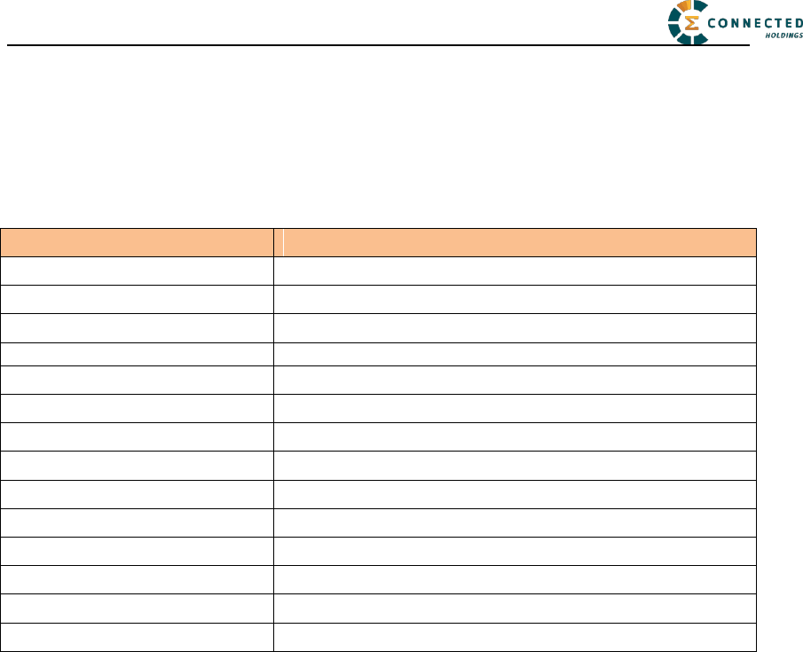
Test Environment Construct
Message Test environment
1. USB dongle and PC as message server
2. Send message to AR-2GM
UDP Test environment
1. Connect dongle to PC and create dialup as ip server
2. AR-2GM create IP connection to server
UART Test environment
1. Connect AR-2GM to pc with com serial cable
2. Open Terminal tool and send at command
3. Response can be shown at terminal window
© 2016 Connected Holdings LLC 17 / 19
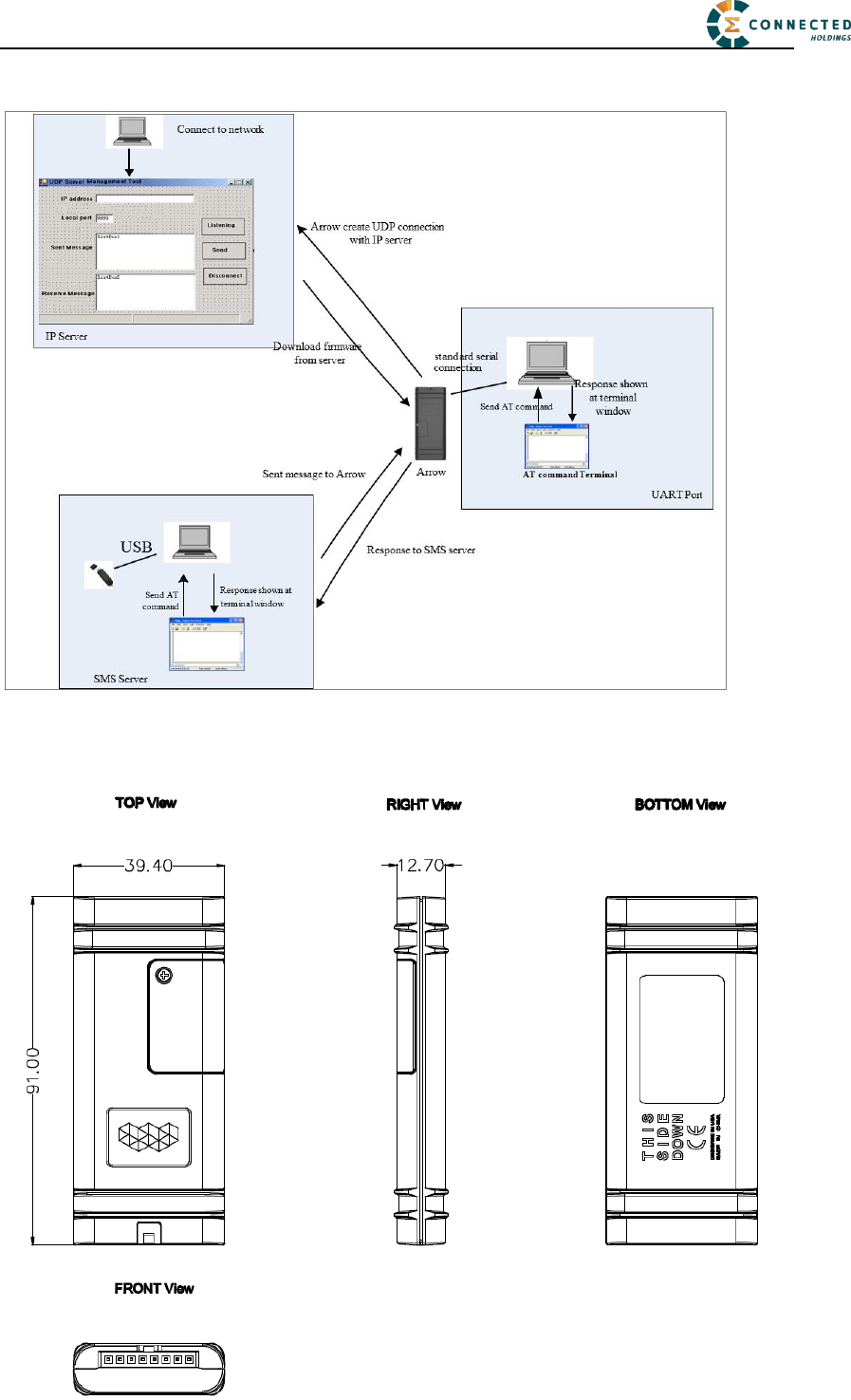
Mechanical Structure(mm)

© 2016 Connected Holdings LLC 18 / 19
FCC Statement
This equipment has been tested and found to comply with the limits for a Class B digital device,
pursuant to Part 15 of the FCC Rules. These limits are designed to provide reasonable protection
against harmful interference in a residential installation. This equipment generates uses and can
radiate radio frequency energy and, if not installed and used in accordance with the instructions,
may cause harmful interference to radio communications. However, there is no guarantee that
interference will not occur in a particular installation. If this equipment does cause harmful
interference to radio or television reception, which can be determined by turning the equipment off
and on, the user is encouraged to try to correct the interference by one or more of the following
measures:
-- Reorient or relocate the receiving antenna.
-- Increase the separation between the equipment and receiver.
-- Connect the equipment into an outlet on a circuit different from that to which the receiver is
connected.
-- Consult the dealer or an experienced radio/TV technician for help.
This device complies with part 15 of the FCC Rules. Operation is subject to the following two
conditions:
(1) This device may not cause harmful interference, and (2) this device must accept any
interference received, including interference that may cause undesired operation.
Changes or modifications not expressly approved by the party responsible for compliance could
void the user's authority to operate the equipment.
RF Exposure Warning Statements:
The antenna(s) used for this transmitter must be installed to provide a separation distance of at
least 20 cm from all persons during the normal operations.
IC STATEMENT
This device complies with Industry Canada licence-exempt RSS standard(s). Operation is subject
to the following two conditions: (1) this device may not cause interference, and (2) this device
must accept any interference, including interference that may cause undesired operation of the
device.
Le présent appareil est conforme aux CNR d'Industrie Canada applicables aux appareils radio
exempts de licence. L'exploitation est autorisée aux deux conditions suivantes : (1) l'appareil ne
doit pas produire de brouillage, et (2) l'utilisateur de l'appareil doit accepter tout brouillage
radioélectrique subi, même si le brouillage est susceptible d'en compromettre le fonctionnement.
In order to avoid the possibility of exceeding the IC radio frequency exposure limits, human

© 2016 Connected Holdings LLC 19 / 19
proximity to the antenna shall not be less than 20cm (8 inches) during normal operation.
Afin d'éviter la possibilité de dépasser les limites d'exposition aux fréquences radio de la IC
CNR102, la proximité humaine à l'antenne ne doit pas être inférieure à 20 cm (8 pouces) pendant
le fonctionnement normal.