Connected ARROWG01 GPS TRACKER User Manual Reset switch
Connected Holdings LLC GPS TRACKER Reset switch
User Manual

Confidential Preliminary – Subject to Change
2015 Connected Holdings LLC Page 1 of 11
Product Description
For the
Arrow Vehicle Tracking Device
By
Connected Holdings LLC
Jan 1, 2015
Document reference
Revision: X1.00
Author: Mr. Edmund Lee
Proofed by: Mr. Zeev Collin
Release date: Date first printed above
File name: ARROW_Overview_Specification_X100_030112
Authorized Recipients
Executive management as provided to and are bound by a Non-Disclosure Agreement
(NDA) in favor of Connected Holdings LLC, its parent or its agent and preventing
disclosure or misuse of the confidential information herein.
The information presented in this document is strictly confidential and contains trade
secrets and other confidential information that are the exclusive property of Connected
Holdings LLC, its parent, subsidiaries or agents.

Confidential Preliminary – Subject to Change
2015 Connected Holdings LLC Page 2 of 11
Description
The ARROW GPS Tracker is a self contained, integrated commercial grade vehicle
tracking device that uses GPS satellite location in combination with a quad band
GSM/GPRS cellular radio connection to report that location.
All antennas including the GPS patch and GSM antenna are internal to the device. Data
reporting can be initiated by a server or by the tracker itself via GSM/GPRS SMS or UDP
pathways or over a physical USB connection.
The ARROW is comprised of a simple two piece plastic enclosure that is snapped
together for reliability, durability and low cost assembly. Interface signals and power are
ported through a connector socket at one end with 8pin wire connector.
The ARROW is based on chip level design as opposed to the traditional approach of
using a third party communications module with an external processor. The application
software executes on the base level Central Processing Unit (CPU) under direct real-time
Operating System (OS) control. This approach provides a much more reliable, lower
power and faster response time than module/processor architectures. Unlike common
module/processor based designs; the ARROW design allows direct operating system
access by the application, thus mitigating the need and for a redundant external processor
and the associated power and cost.
For added redundancy against system lockup, a physically separate, dedicated watchdog
circuit oversees the ARROW system operation. If the system does not maintain the
watchdog circuit through programmed reporting, the system power is cycled and a new
GPS satellite and cellular connection is established.
The ARROW can be provisioned for UDP and SMS data services for application
command and/or data transactions within the 850, 900, 1800 and 1900 MHz GSM bands.
Network provisioning is done using embedded SIM technology for reliability and cost
savings. For added safeguard against network connection loss, a hardware ARROW
endpoint reset and reboot can be initiated by simply calling the provisioned phone
number and allowing it to ring three times.
Flexible I/O includes 2 bidirectional General Purpose Input Output (GPIO) ports. A
separate dedicated USB port is provided for general use as well as development and
programming support. A high current relay drive is provided for starter motor solenoid
control or general purpose drive (current sink only).
Over The Air (OTA) application firmware updates are supported through at TFTP
connection to a server. The entire application image can be updated using one
specialized SMS or USB command.
All inputs are electrically hardened against overvoltage and over current conditions
present in automotive environments. This includes transient electrical noise and
Electrostatic Discharge (ESD). The power input is further protected against over current
with an internal self-resetting fuse.
The ARROW is physically disguised to appear to be a nondescript part of the cabling
system. It is a small black box with unremarkable features. Two LED status indicators
are provided to verify correct installation and initial operation. A unique power

Confidential Preliminary – Subject to Change
2015 Connected Holdings LLC Page 3 of 11
management feature allows these LEDs to be extinguished once installation is verified to
be correct. This feature reduces power and further conceals the ION Tracker from
untrained parties wishing to defeat its operation.
As with all GPS location devices, the ARROW should be installed in a vehicle such that
it has an unobstructed view of the sky during normal operation. Double sided foam tape
can be used to secure the surface not facing the sky if needed.
A factory populate option is provided to add a backup battery and motion detector to the
main board. Under software control, this motion detector can be used to wake the
ARROW from a very low power state.

Confidential Preliminary – Subject to Change
2015 Connected Holdings LLC Page 4 of 11
Bullet Specifications
________________________________________________________________________
Cellular: 850/900/1800/1900 MHz Quad band
GSM/GPRS Protocol CS-1, CS-2, CS-3 and CS-4
Output power:
Class 4 (2W) @ 850/900MHz
> 24dB @ 850/900MHz (OTA TRP)
Class 1 (1W) @ 1800/1900MHz
> 26.5dB @ 1800/1900MHz (OTA TRP)
Sensitivity:
< -107dBm @ 850/900MHz (Conducted)
< -101dBm @ 850/900MHz (OTA TIS)
< -106dBm @ 1800/1900MHz (Conducted)
< -103.5dBm @ 1800/1900MHz (OTA TIS)
Antenna:
Integrated onto PCB
Meets minimum AT&T TRP/TIS requirements
________________________________________________________________________
Services: GPRS Multi slot class 12
SMS (Text):
UDP data
DNS address resolution
GSM circuit switched hard reboot
________________________________________________________________________

Confidential Preliminary – Subject to Change
2015 Connected Holdings LLC Page 5 of 11
________________________________________________________________________
GPS: L1-band (1.57542GHz)
Channels:
210 PRN
66 Search
22 Simultaneous tracking
Sensitivity (UHIS):
Tracking: -165dBm
Reacquisition: -158dBm
Acquisition: -149dBm
Acquisition time:
Hot: <1.5s
Warm: <34s
Cold: <90s
Reacquisition: <1.0s
WAAS:
Position: <3m
Velocity: >0.1m/s
Acceleration: >0.1m/s2
Altitude: 18,000m (max)
Velocity: 515m/s (max)
Acceleration: 4G (max)
32 Geo fences
Coil antenna
________________________________________________________________________

Confidential Preliminary – Subject to Change
2015 Connected Holdings LLC Page 6 of 11
________________________________________________________________________
I/O: One main port and one internal expansion port
All pins are 16V tolerant and ESD protected
Pigtail:
2-Leads 2.8V GPIO
2-Leads USB2.0
Data+
Data-
1-Pin relay drive
-500mA drive
TVS overvoltage protection
1-Pin power input:
1.0A resetting fuse
TVS overvoltage protection
1-Pin ground
SIM: Internal embedded
LED: Red GSM status
Green GPS status
Battery voltage measurement
________________________________________________________________________
Power: Vin:
6.0 – 15.0VDC
Full Shutdown: < 50µA
Standby: < 800µA (GSM Idle)
GPS acquisition: < 40.0mA (GSM Idle)
GPS tracking: < 36 mA (GSM Idle)
GSM dedicated: < 36.0mA (GPS Off)
GPRS max power: < 90.0mA (GPS Off)
Peak instantaneous < 600mA

Confidential Preliminary – Subject to Change
2015 Connected Holdings LLC Page 7 of 11
_______________________________________________________________________
Software: Native ARM processor execution
Proprietary application
Extended AT command interface
Easily configured reports to minimize data transport costs
Based on proven GSM/GPRS modem stack
Lockup protection:
Independent watchdog with power cycle reset and reboot
GSM circuit switched reset
Flash memory:
8MB for application and data storage
Report buffer
USB port update
Over the air update
________________________________________________________________________
Options: Backup Battery
Motion sensor
________________________________________________________________________
Physical: Design: Nondescript design
Color: Black
Material: UL Lanxess PA6 Durethan BKV15+
Size: L91mm x W39.4mm x D13.7mm
SIM: Keyed retainer socket
________________________________________________________________________
Environment: Temperature:
-40 to 85° C Operation
-50 to +100° C Storage
Humidity:
20% to 90% Operation
10% to 95% Storage
ESD: 15KV immune on all user accessible surfaces and ports
Altitude: -500 to +18,000m
Shock: 25G
Vibration: Sinusoidal/random
________________________________________________________________________
Confidential Preliminary – Subject to Change
2015 Connected Holdings LLC Page 8 of 11
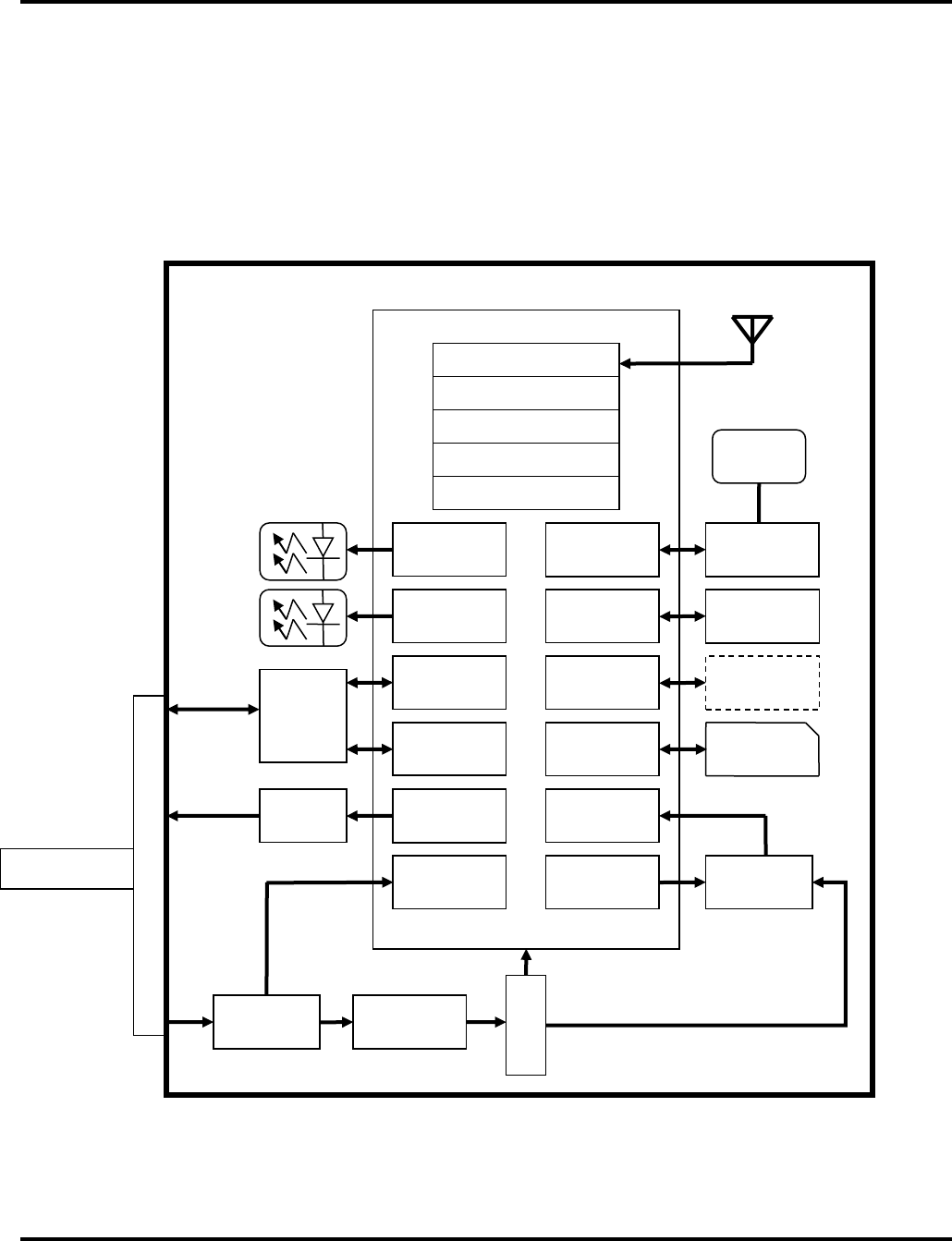
GPRS Chipset
ARM
Cellular Base Band
Figure 1
ION-X Hardware Architecture Block Diagram
DSP
LED
Driver
GPIO
Signal
Conditioning
DC/DC
Converter
Power
Conditioning
Patch
Antenna
PCB
Antenna
Strain Relief
RF Interface
GPIO
Relay
Driver
Watchdog
Controller
GPIO
Reset/Power
Combiner
Timing
SIM
Interface Embedded
SIM
A/D
Red
Green
UART
USB2.0
Memory
Interface
I2C
Flash/SRAM
Memory
Motion
Detection
LED
Driver GPS Single
Chip Receiver
Main PCB
8pin Connector
Hardware Architecture
Figure 1 shows a high level block diagram of the ARROW system hardware. The core
architecture is defined a highly integrated GPRS chipset and single chip GPS receiver.
The motion detector is optionally populated at assembly time. Signal and power
interface to the PCB is through a 8pin connector harness.
Confidential Preliminary – Subject to Change
2015 Connected Holdings LLC Page 9 of 11
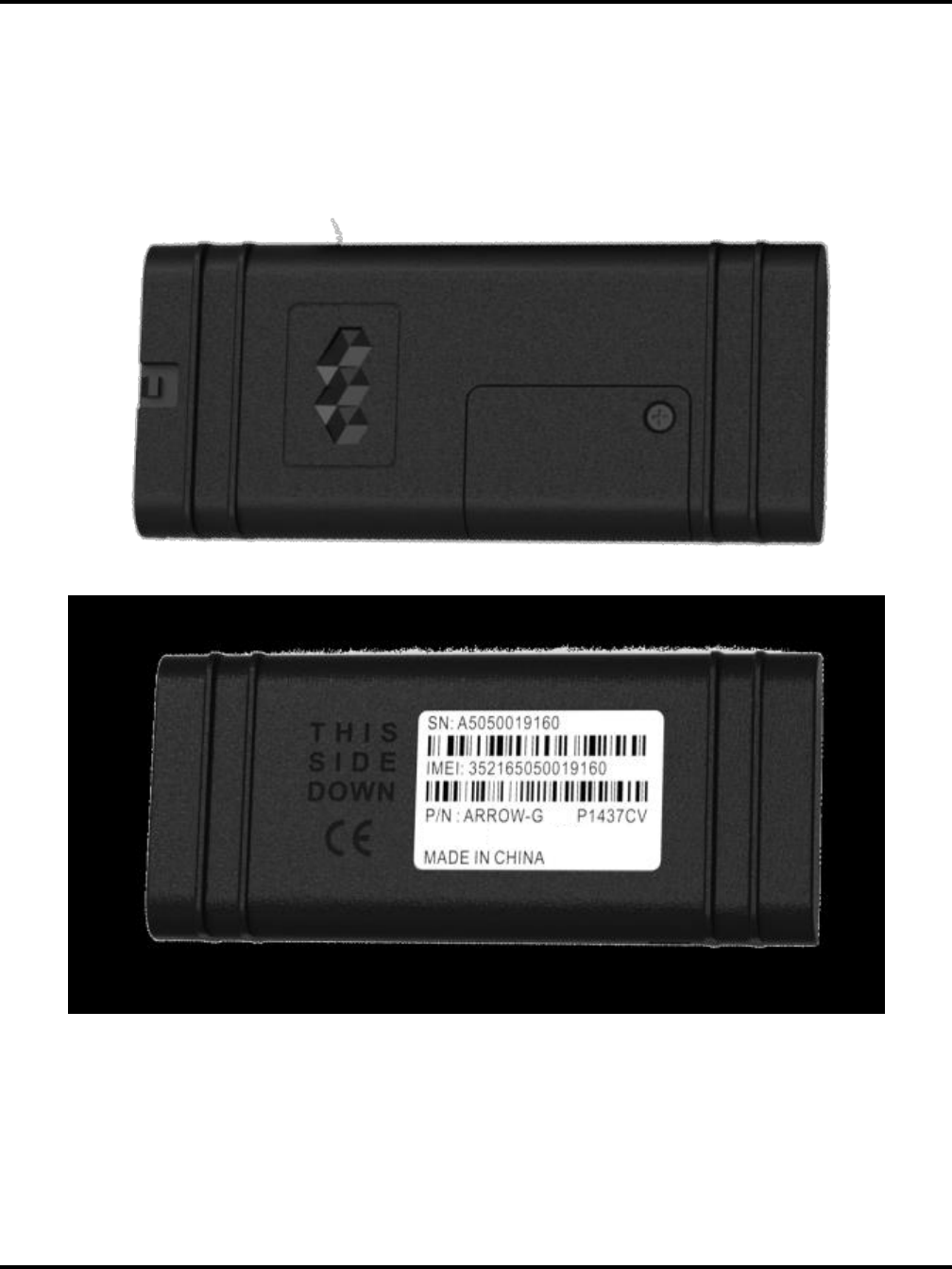
Physical Attributes
Figures 2 show various exterior views and dimensions of the ARROW Tracker and some
critical physical features.
Figures 2

Confidential Preliminary – Subject to Change
2015 Connected Holdings LLC Page 10 of 11
Variants
Model
Description
Remarks
Arrow-G
GPRS GPS Tracker – Standard
Arrow-G-BA
GPRS GPS Tracker with Built-in Backup Battery
Arrow-G-BG
GPRS GPS Tracker with Built-in Backup Battery &
Motion Sensor
FCC Statement
This device complies with Part 15 of the FCC Rules.
Operation is subject to the following two conditions: (1) This device may not cause
harmful interference, and (2) This device must accept any interference received,
including interference that may cause undesired operation.
The grantee is not responsible for any changes or modifications not expressly approved
by the party responsible for compliance. Such modifications could void the user’s
authority to operate the equipment.
This equipment has been tested and found to comply with the limits for a Class B digital
device, pursuant to part 15 of the FCC Rules. These limits are designed to provide
reasonable protection against harmful interference in a residential installation. This
equipment generates, uses and can radiate radio frequency energy and, if not installed and
used in accordance with the instructions, may cause harmful interference to radio
communications. However, there is no guarantee that interference will not occur in a
particular installation. If this equipment does cause harmful interference to radio or
television reception, which can be determined by turning the equipment off and on, the
user is encouraged to try to correct the interference by one or more of the following
measures:
—Reorient or relocate the receiving antenna.
—Increase the separation between the equipment and receiver.
—Connect the equipment into an outlet on a circuit different from that to which the
receiver is connected.
—Consult the dealer or an experienced radio/TV technician for help.
FCC RF Radiation Exposure Statement:
This equipment complies with FCC RF radiation exposure limits set forth for an
uncontrolled environment. This equipment should be installed and operated with a
minimum distance of 20 centimeters between the radiator and your body.
IC Statement
This device complies with Industry Canada licence‐exempt RSS standard(s). Operation is
subject to the following two conditions: (1) this device may not cause interference, and (2)
this device must accept any interference, including interference that may cause undesired
operation of the device.

Confidential Preliminary – Subject to Change
2015 Connected Holdings LLC Page 11 of 11
CAN ICES-3(B)/NMB-3(B)
Le présent appareil est conforme aux CNR d’Industrie Canada applicables aux appareils
radio exempts de licence. L’exploitation est autorisée aux deux conditions suivantes :
(1) l’appareil ne doit pas produire de brouillage;
(2) l’utilisateur de l’appareil doit accepter tout brouillage radioélectrique subi, même si le
brouillage est susceptible d’en compromettre le fonctionnement.
CAN ICES-3(B)/NMB-3(B)
IC RF Radiation Exposure Statement:
This equipment complies with IC RF radiation exposure limits set forth for an
uncontrolled environment. This equipment should be installed and operated with a
minimum distance of 20 centimeters between the radiator and your body.
Déclaration de rayonnement RF exposée IC:
Ce dispositif conforme aux valeurs limites d'exposition pour les rayonnements RF
présente un environnement non contrôlé.Le dispositif dissipateur de chaleur et le corps
entre l'installation et la distance minimale de 20 cm de fonctionner.