Consilium Marine US 0009N011 30K WATT S BAND MARINE RADAR User Manual 303766P001 Rev C
Consilium Marine US Inc. 30K WATT S BAND MARINE RADAR 303766P001 Rev C
Contents
- 1. Users Manual 1
- 2. Users Manual 2
Users Manual 1

303766P001
Rev. C
DECEMBER 2007
30KW S-BAND/U
ANTENNA GROUP
TYPE
03R039
09N-011
02R-039B
TECHNICAL
MANUAL

CONSILIUM SELESMAR s.r.l.
Head Office & Plant
Via Romita, 26 - 50020 Montagnana V. P. (Florence) Italy
Tel.: +39/0571/68121 Telefax +39/0571/670798
303766P001
Rev. C
DECEMBER 2007
S-BAND ANTENNA GROUP
INCLUDING 12 FEET ANTENNA
AND PEDESTAL WITH 30 kW
TRANSCEIVER UPMAST
TYPE
03R-039
09N-011
02R-039B
TECHNICAL MANUAL

30 kW S-BAND/U ANTENNA GROUP
FOREWORD
A Rev. C
APPLICATION FOR MANUAL REVISIONS
Upon receipt of this manual, please fill in the necessary data. It is
important that the addressee be the end user so that the operating
personnel will receive all revisions to the manual
EQUIPMENT NAME .............................................................................................
SERIAL No...................................... MODEL ......................................................
MANUAL TITLE ....................................................................................................
........................................................ MANUAL PART NUMBER.........................
ISSUED INDEX............................... REVISION INDEX......................................
PURCHASING AGENCY......................................................................................
NAME OF USER...................................................................................................
ADDRESS OF USER............................................................................................
.............................................................................................................
.............................................................................................................
ATTN:...................................................................................................

30 kW S-BAND/U ANTENNA GROUP
FOREWORD
B Rev. C
RECORD OF CHANGES
RCS CODE/REV. INDEX DATE PURPOSE OF THE
CHANGE
CHANGE
REQUESTED BY
Revision A 30/11/2000 First Emission
Revision B
June 2004
General Revision
Revision C December
2007
Replaced pag. B and
pag. 7.2.
Request of Changes
034/07

30 kW S-BAND/U ANTENNA GROUP
FOREWORD
C Rev. C
MANUAL TABLE OF CONTENTS
Warnings
Chapter 1 DESCRIPTION AND MAIN CHARACTERISTICS
Chapter 2 OPERATION
Chapter 3 FUNCTIONAL DESCRIPTION
Chapter 4 PREVENTIVE MAINTENANCE
Chapter 5 TROUBLESHOOTING
Chapter 6 CORRECTIVE MAINTENANCE
Chapter 7 PART LIST
Chapter 8 INSTALLATION
Chapter 9 FIGURES

30 kW S-BAND/U ANTENNA GROUP
INDEX
i Rev. C
TABLE OF CONTENTS
CHAPTER 1
DESCRIPTION AND MAIN CHARACTERISTICS .................................................... 1.1
1.1 Introduction................................................................................................................. 1.1
1.1.1 Manual Applicability.................................................................................................... 1.1
1.1.2 Purpose of the Equipment.......................................................................................... 1.1
1.1.3 List of Abbreviation ..................................................................................................... 1.2
1.2 Physical description.................................................................................................... 1.2
1.2.1 Composition................................................................................................................ 1.2
1.2.2 TRANSCEIVER Unit................................................................................................... 1.3
1.2.3 Antenna Pedestal S/U ................................................................................................ 1.4
1.2.3.1 03R-039 Pedestal....................................................................................................... 1.4
1.2.4 Antenna ...................................................................................................................... 1.5
1.3 Functional description................................................................................................. 1.5
1.3.1.1 Transceiver Unit ......................................................................................................... 1.5
1.4 Technical characteristics ............................................................................................ 1.6
1.4.1.1 Transceiver Unit ......................................................................................................... 1.6
CHAPTER 2
OPERATION .............................................................................................................. 2.1
2.1 Introduction................................................................................................................. 2.1
2.1.1 Purpose ...................................................................................................................... 2.1
2.2 Controls and indicators............................................................................................... 2.1
2.3 Semi-operative controls.............................................................................................. 2.1
CHAPTER 3
FUNCTIONAL DESCRIPTION .................................................................................. 3.1
3.1 Introduction................................................................................................................. 3.1
3.2 Functional description................................................................................................. 3.2
3.3 Transceiver unit technical description ........................................................................ 3.4
3.3.1 General....................................................................................................................... 3.4
3.3.2 POWER MOS Board .................................................................................................. 3.4
3.3.2.1 High Voltage Power Supply (HVPS) Generator Circuit.............................................. 3.4
3.3.2.2 Pulse Generator Circuit .............................................................................................. 3.5
3.3.2.3 15V ISO and 120 V Generation.................................................................................. 3.6
3.3.3 RTM CONT B Board................................................................................................... 3.6
3.3.3.1 Low Voltage Power Supply Circuit (LVPS) ................................................................ 3.6
3.3.3.2 Microprocessor and Gate Array ................................................................................. 3.7
3.3.3.2.1 General description .................................................................................................... 3.7
3.3.3.2.2 Functions Performed .................................................................................................. 3.7
3.3.3.2.3 Input Signals............................................................................................................... 3.8
3.3.3.2.4 Output Signals ............................................................................................................ 3.9
3.3.3.3 Pulse Length Generator Function ............................................................................ 3.10
3.3.3.4 Azimuth and Heading Line Signal Circuit Generator................................................ 3.11
3.3.3.5 Performance Monitor Function ................................................................................. 3.11
3.3.4 Solid State R.F. Head............................................................................................... 3.11
3.3.5 NIFB Assy................................................................................................................. 3.12
3.4 Antenna pedestal...................................................................................................... 3.13
3.4.1 General..................................................................................................................... 3.13
3.4.2 Pedestal Type 03R-039............................................................................................ 3.13
CHAPTER 4
PREVENTIVE MAINTENANCE................................................................................. 4.1
4.1 Introduction................................................................................................................. 4.1
4.2 Preventive maintenance procedure............................................................................ 4.1

30 kW S-BAND/U ANTENNA GROUP
INDEX
ii Rev. C
CHAPTER 5
TROUBLESHOOTING............................................................................................... 5.1
5.1 Introduction................................................................................................................. 5.1
5.1.1 General....................................................................................................................... 5.1
5.1.2 Organisation ............................................................................................................... 5.1
5.1.3 Personnel ................................................................................................................... 5.1
5.1.4 Tools and Instruments................................................................................................ 5.1
5.2 Troubleshooting Procedures ...................................................................................... 5.2
5.2.1 Safety Precautions ..................................................................................................... 5.2
5.2.2 Troubleshooting Operations ....................................................................................... 5.2
CHAPTER 6
CORRECTIVE MAINTENANCE ................................................................................ 6.1
6.1 General....................................................................................................................... 6.1
6.1.1 Introduction................................................................................................................. 6.1
6.1.2 Safety Precautions ..................................................................................................... 6.1
6.1.3 Personnel ................................................................................................................... 6.1
6.1.4 Required Tools and Instruments ................................................................................ 6.1
6.2 Corrective maintenance procedures .......................................................................... 6.2
6.2.1 Replacement Procedures for the TRANSCEIVER Unit ............................................. 6.2
6.2.1.1 Replacement of a Fuse .............................................................................................. 6.2
6.2.1.2 Replacement of the POWER MOS Board.................................................................. 6.3
6.2.1.3 Replacement of the LNFE Assy ................................................................................. 6.3
6.2.1.4 Replacement of the RTM CONT B Board .................................................................. 6.4
6.2.1.5 Replacement of the NIFB Assy .................................................................................. 6.5
6.2.1.6 Replacement of the Magnetron .................................................................................. 6.5
6.2.2 Replacement Procedures for the Antenna Pedestal S/U Unit ................................... 6.5
6.2.2.1 Driving Belt Replacement........................................................................................... 6.5
6.2.2.2 Motor Replacement .................................................................................................... 6.6
6.2.2.3 Reduction Group Replacement .................................................................................. 6.6
6.2.2.4 3 Filter Replacement................................................................................................ 6.7
6.2.2.5 Rotating Joint Replacement ....................................................................................... 6.7
6.2.2.6 Antsign Board Replacement....................................................................................... 6.8
6.2.2.7 Optical Read-out Board Replacement ....................................................................... 6.9
6.2.2.8 Antenna Generator Disk Replacement ...................................................................... 6.9
6.2.3 Belt installation tension............................................................................................. 6.11
CHAPTER 7
PART LIST ................................................................................................................. 7.1
7.1 Introduction................................................................................................................. 7.1
7.1.1 Part List....................................................................................................................... 7.1
7.1.2 Part Location Illustration ............................................................................................. 7.1
7.2 Part list tables ............................................................................................................. 7.2
CHAPTER 8
INSTALLATION ......................................................................................................... 8.1
8.1 Introduction................................................................................................................. 8.2
8.1.1 Shipping...................................................................................................................... 8.2
8.1.2 Unpacking................................................................................................................... 8.2
8.1.3 Storage ....................................................................................................................... 8.3
8.1.4 Handling...................................................................................................................... 8.3
8.2 Specifications ............................................................................................................. 8.3
8.2.1 Dimensions and weights (also see outline drawings) ................................................ 8.3
8.2.2 Required power .......................................................................................................... 8.4
8.2.3 Environmental Data .................................................................................................... 8.4
8.3 Installation................................................................................................................... 8.4
8.3.1 Installation Principles.................................................................................................. 8.4
8.3.2 Mechanical installation ............................................................................................... 8.6
8.3.2.1 Pedestal with transceiver ........................................................................................... 8.6
8.3.2.2 Antenna ...................................................................................................................... 8.7
8.3.2.3 Safety Switch .............................................................................................................. 8.7
8.3.2.4 Performance Monitor Arm .......................................................................................... 8.8

30 kW S-BAND/U ANTENNA GROUP
INDEX
iii Rev. C
8.3.3 Electrical installation ...................................................................................................8.8
8.3.3.1 Multicore Cable........................................................................................................... 8.8
8.3.3.2 Safety Switch .............................................................................................................. 8.9
8.3.3.3 Performance Monitor Arm .......................................................................................... 8.9
8.3.3.4 Grounding................................................................................................................... 8.9
8.3.3.5 Installation Check-out ............................................................................................... 8.10
8.3.4 Pre Setup Procedures .............................................................................................. 8.10
8.3.4.1 Antenna Turning Motor power Voltage and Phase .................................................. 8.10
8.3.4.2 Head Line alignment procedure ............................................................................... 8.11
8.4 Installation figures and drawings .............................................................................. 8.12
8.5 Annex........................................................................................................................ 8.24
CHAPTER 9
FIGURES.................................................................................................................... 9.1
Figure 9.1.1 30 kW S-BAND/U Antenna Group - Overall View ...................................................... 9.2
Figure 9.1.2 RTM 30S/U/D - External View.................................................................................... 9.3
Figure 9.1.3 30 kW S-BAND/U Antenna Group Internal View........................................................ 9.4
Figure 9.1.4 03R-039 Antenna Pedestal External View ................................................................. 9.5
Figure 9.1.5 03R-039 Antenna Pedestal Internal View .................................................................. 9.6
Figure 9.1.6 30 kW S-BAND/U Antenna Group Block Diagram ..................................................... 9.7
Figure 9.1.7 RTM 30S/U/D Unit - Internal View.............................................................................. 9.8
Figure 9.1.8 RTM 30S/U/D Unit - RTM CONT B Board ................................................................. 9.9
Figure 9.1.9 30 kW S-BAND/U Antenna Group Functional Block Diagram ................................. 9.10
Figure 9.1.10 POWER MOS Board - HVPS Generator Circuit ...................................................... 9.11
Figure 9.1.11 POWER MOS Board - Pulse Generator Circuit ....................................................... 9.12
Figure 9.1.12 RTM CONT B board - LVPS Circuit ......................................................................... 9.13
Figure 9.1.13 RTM CONT B board – Microprocessor .................................................................... 9.14
Figure 9.1.14 RTM CONT B board - AZ and HL Signals Generator Circuit................................... 9.15
Figure 9.1.15 Performance Monitor Circuit..................................................................................... 9.16
Figure 9.1.16 RF Head - Functional Block Diagram....................................................................... 9.17
Figure 9.1.17 NIFB Assy................................................................................................................. 9.18
Figure 9.1.18 RTM 30S/U/D Cabling .............................................................................................. 9.19
Figure 9.1.19 30 kW S-BAND/U Antenna Group - RTM 30S/U/D Unit Front View ........................ 9.20
Figure 9.1.20 30 kW S-BAND/U Antenna Group - RTM 30S/U/D Unit Internal View .................... 9.21
Figure 9.1.21 RTM 30S/U/D Unit - Particular of the Magnetron..................................................... 9.22
Figure 9.1.22 RTM 30S/U/D Unit - RTM CONT B board................................................................ 9.23
Figure 9.1.23 Antenna Pedestal S/U Unit - External View ............................................................. 9.24
Figure 9.1.24 Chart 1 ...................................................................................................................... 9.25
Figure 9.1.25 Chart 2 ...................................................................................................................... 9.28
Figure 9.1.26 Chart 3 ...................................................................................................................... 9.29
Figure 9.1.27 Chart 4 ...................................................................................................................... 9.30
Figure 9.1.28 Chart 5 ...................................................................................................................... 9.31
Figure 9.1.29 RTM 30S/U/D Unit - External View .......................................................................... 9.32
Figure 9.1.30 RTM 30S/U/D Unit - Internal View............................................................................ 9.33
Figure 9.1.31 RTM 30S/U/D Unit - Internal View of the Cover....................................................... 9.34
Figure 9.1.32 Antenna Pedestal S/U Unit with Performance Monitor - External View ................... 9.35
Figure 9.1.33 Antenna Pedestal S/U Unit - Internal View............................................................... 9.36
Figure 9.1.34 Antenna Pedestal S/U Unit - Particular of the Motor................................................ 9.37
Figure 9.1.35 30 kW S-BAND/U Antenna Group............................................................................ 9.38
Figure 9.1.36 RTM 30S/U/D Unit - Internal View............................................................................ 9.39
Figure 9.1.37 Antenna Pedestal S/U Unit Normal Speed - External View ..................................... 9.40
Figure 9.1.38 Antenna Pedestal S/U Unit Normal Speed - Internal View ...................................... 9.41

30 kW S-BAND/U ANTENNA GROUP
INDEX
iv Rev. C
LIST OF TABLES
Table 1.1.1 - List of Abbreviations............................................................................................................. 1.2
Table 1.2.1 - Equipment, Accessories And Document Supplied .............................................................. 1.3
Table 1.2.2 - Transceiver Unit Composition.............................................................................................. 1.3
Table 1.4.1 - Transceiver Unit Technical Characteristics ......................................................................... 1.6
Table 1.4.2 - Pedestal Type 03r-039 Technical Characteristics ............................................................... 1.7
Table 1.4.3 - Pedestal Type 03R-040 Technical Characteristics.............................................................. 1.7
Table 1.4.4 - 12’ S Band Antenna Technical Characteristics ................................................................... 1.7
Table 2.3.1 - Semi-operative Controls Location of the the RTM 30S/U/D CABINET ............................... 2.1
Table 2.3.2 - Semi-operative Controls Location of the RTM CONT B board............................................ 2.1
Table 3.3.1 - Microprocessor Input Signals .............................................................................................. 3.8
Table 3.3.2 - Gate Array Input Signals...................................................................................................... 3.9
Table 3.3.3 - Microprocessor Output Signals............................................................................................ 3.9
Table 3.3.4 - Gate Array Output Signals ................................................................................................. 3.10
Table 4.2.1 - List of Recommended Tools and Instruments ..................................................................... 4.2
Table 4.2.2 - List of the Preventive Maintenance Cards ........................................................................... 4.2
Table 5.1.1 - List of Recommended Instruments ...................................................................................... 5.1
Table 5.2.2 - List of Main Possible Failures .............................................................................................. 5.2
Table 6.2.1 - List of the Corrective Maintenance Procedures................................................................... 6.2
Table 7.2.1 - List of Items Shown in Chapter 9, Fig 7.2.1 30 kW S-BAND/U Antenna Group .......... 7.2
Table 7.2.2 - Parts List of the RTM 30S/U/D Unit ..................................................................................... 7.2
Table 7.2.3 - Parts List of the Antenna Pedestal S/U Unit Type 03R-039 ................................................ 7.2

30 kW S-BAND/U ANTENNA GROUP
WARNINGS
1 Rev. C
WARNINGS
HIGH VOLTAGE
Radar equipment requires the use of high voltage, which can cause injury, or
loss of life. Danger exists only when the units are opened exposing internal
circuits, as when servicing the equipment. The Manufacturer Radar has been
carefully designed to protect personnel from possible injury from high voltages.
Nevertheless, it is recommended that the Line Switch always be opened as an
added protection when inspecting or servicing the equipment.
Although every effort has been made to eliminate danger to personnel, no
responsibility is accepted for any injury or loss of life suffered in connection with
this equipment.
X-RAY RADIATION
X-RAY radiation may be generated by Transceiver units and care must be
taken to avoid possible harmful effects when they are opened for maintenance.
When power is on, care should be taken not to approach closer than 1 ft. from
the unit unless front cover is in place.
RADIO-FREQUENCY RADIATION
Harmful effects (particularly to the eyes) may be caused by exposure of any
part of the human body to radio-frequency mean power densities in excess of
100 mW/cm2. This power density is exceeded at a distance of 1 ft. or less, from
the 12 ft. X-Band aerial (when stationary).
The system is however designed to disable radiation when the antenna is not
rotating.
The pedestals have also been predisposed for the installation of an external
safety switch, which can be mounted on, or near the platform. This switch
removes power from the Pedestal eliminating the possibility of accidental
operation during servicing and also causes disabling of transmission.
Whenever it is necessary to disconnect the waveguide system from a radar
transmitter for maintenance purpose, the transmitter output should, when
practicable, be terminated in a matched load. If this is not possible, care should
be taken to avoid standing in front of an open-ended waveguide from which
power is being radiated.
NEVER look down a waveguide from which power is being radiated.
SAFETY SWITCH
The Unit is provided of a safety switch, which disable the Antenna movement
during maintenance operations.

30 kW S-BAND/U ANTENNA GROUP
WARNINGS
2 Rev. C
SAFETY PRECAUTIONS
Purpose
The safety precautions described in this paragraph are applicable to 30 kW S-
BAND/U Antenna Group. Depending upon the material to be highlighted, the
following attention letter headings are used in the technical manual content.
WARNING
THIS IS OPERATING OR MAINTENANCE PROCEDURE,
PRACTICE, CONDITION AND STATEMENT WHICH. IF NOT
STRICTLY FOLLOWED, COULD RESULT IN INJURY TO OR
DEATH OF PERSONNEL
WARNING
THIS IS OPERATING OR MAINTENANCE PROCEDURE,
PRACTICE, CONDITION AND STATEMENT WHICH. IF NOT
STRICTLY OBSERVED, COULD RESULT IN DAMAGE TO,
OR DESTRUCTION OF, UNIT OR LOSS OF EMISSION
EFFECTIVENESS.
NOTE
An essensial operating or maintenance procedure, condition or
statement which must be highlighted
Whenever a precaution, relating specifically to a part of the technical manual is
needed, the information is given in the relevant part of the manual. Warnings
and Cautions precede applicable text.
Safety Operations
During normal operation (front cover closed), the unit can be quickly
disconnected from the main power line, setting to OFF the relevant circuit
breaker located on the electric switchboard.
During maintenance (front cover opened) it is possible to turn-on the unit by
setting to SERVICE MODE the SW2 switch, mounted on the RTM Supply Assy.
This switch is connected in parallel with the relay, controlled by the POWER ON
command, and during normal operation must be set to NORMAL. During
maintenance, in order to prevent RTM occasional turning-on it is better to
disconnect and insulate, momentarily, PWON terminal from the relevant
terminal board.
NOTE
Main power line is always present on terminal board and on
fuses

30 kW S-BAND/U ANTENNA GROUP
WARNINGS
3 Rev. C
Safety Summary
The following are general safety precautions that are not related to any specific
procedure and therefore do not appear elsewhere in this technical manual.
These are recommended precautions that personnel must understand and
apply during most phases of operation and maintenance.
KEEP AWAY FROM LIVE CIRCUIT
Operating personnel must at all times observe all safety regulations.
Do not replace components or make adjustments inside the unit with the high
voltage supply turned ON. Under certain conditions, dangerous potentials may
exist when the power breaker is in the OFF position, also due to charges
retained by capacitors. To avoid casualties, always remove power and
discharge to ground a circuit before touching it.
DO NOT SERVICE OR ADJUST ALONE
Under no circumstances should any person initiate servicing or adjusting the
unit except in the presence of someone capable of helping help.
RESUSCITATION
Personnel working with or near high voltage should be familiar with modern
methods of resuscitation. Such information may be obtained from the Bureau of
Medicine and Surgery.
Warning Information
The following warnings appear in the text of this technical manual, and are
repeated here for emphasis.
WARNING
USE EXTREME CARE WHEN WORKING ON THE UNIT
ONCE THE COVER HAS BEEN OPENED. THE MAGNETRON
ASSEMBLY OPERATES AT VOLTAGES THAT MAY PROVE
FATAL
WARNING
BEWARE OF HIGH VOLTAGE CAPACITORS. IT IS
NECESSARY TO SHORT-CIRCUIT THEIR LEADS BEFORE
PERFORMING ANY MAINTENANCE ACTION ON THEM.
WARNING
ON THE ELECTRIC SWITCHBOARD, SET TO OFF THE
POWER BREAKER DEDICATED TO THE PRESENT
EQUIPMENT AND HANG TO IT A PLACARD READING:
“WORK IN PROGRESS-DO NOT SWITCH ON”

30 kW S-BAND/U ANTENNA GROUP
WARNINGS
4 Rev. C
WARNING
USE EXTREME CARE WHEN WORKING ON THE
EQUIPMENT ONCE THE FRONT COVER HAS BEEN
OPENED. THE MAGNETRON ASSEMBLY OPERATES AT
VOLTAGES THAT MAY PROVE FATAL
WARNING
SET MAIN LINE BREAKER TO OFF BEFORE REPLACING
ANY FUSE. FUSES ARE UNDER VOLTAGE LEVELS WHICH
MAY PROVE FATAL.

30 kW S-BAND/U ANTENNA GROUP
DESCRIPTION AND MAIN CHARACTERISTICS
1.1 Rev. C
CHAPTER 1
DESCRIPTION AND MAIN
CHARACTERISTICS
1.1 Introduction
1.1.1 Manual Applicability
The present technical manual provides information, data and procedures
relevant to the general description, the operation, the functional description, the
scheduled maintenance, the troubleshooting, the corrective maintenance and
the replaceable parts’ list of the S-Band 30 kW Antenna Group, from now on
called 30 kW S-BAND/U Antenna Group.
The present technical manual contents is arranged in 10 Chapters as follows:
Warnings
Chapter 1 DESCRIPTION AND MAIN CHARACTERISTICS
Chapter 2 OPERATION
Chapter 3 FUNCTIONAL DESCRIPTION
Chapter 4 PREVENTIVE MAINTENANCE
Chapter 5 TROUBLESHOOTING
Chapter 6 CORRECTIVE MAINTENANCE
Chapter 7 PART LIST
Chapter 8 INSTALLATION
Chapter 9 FIGURES
1.1.2 Purpose of the Equipment
The 30 kW S-BAND/U Antenna Group (Chapter 9, Figure 9.1.1), when
connected to a RTM-S Power Supply and to a Display Unit, performs the
echoes transmission and reception in the surrounding area.
The equipment purposes are the following:
- to transmit and to receive the RF to/from the S-Band
Antenna Unit
- to accept and to process data from the S-Band Antenna
- to receive radar controls from the Display Unit
- to transmit radar data and controls to the Display Unit
- to accept mains AC voltage from the Ship Main Line
- to control the antenna pedestal start and movement

30 kW S-BAND/U ANTENNA GROUP
DESCRIPTION AND MAIN CHARACTERISTICS
1.2 Rev. C
1.1.3 List of Abbreviation
Measurement abbreviations are according to MIL STD-12; other terms and
abbreviations used in the present manual are listed in Table 1.1.1 - List of
Abbreviations.
Table 1.1.1 - List of Abbreviations
ABBREVIATION MEANINGS
AC
AZ
DC
dB
dBm
HL
HV
IF
LED
LO
LV
MDS
MTBF
PRF
PS
RC
RF
R.P.M.
RTM
STC
TTL
VCO
WG
Alternating Current
Antenna Azimuth Pulse
Direct Current
Decibel
Decibel referred to 1 mW
Heading Line
High Voltage
Intermediate Frequency
Light Emitting Diode
Local Oscillator
Low Voltage
Minimum Detectable Signal
Mean Time Between Failures
Pulse Repetition Frequency
Power Supply
Resistor - Capacitor
Radio Frequency
Revolutionsper Minute
Receiver Transmitter Modulator
Sensitivity Time Control
Transistor-Transistor Logic
Voltage Controlled Oscillator
Waveguide
1.2 Physical description
1.2.1 Composition
The 30 kW S-BAND/U Antenna Group (Chapter 9, Figure 9.1.1) is composed of
the following Units:
- TRANSCEIVER (pos. 1) which generates the transmitting
pulses and converts the received echoes
- Antenna Pedestal S/U (pos. 2) which allows the Antenna
rotation
- the 12' transmitting/receiving Antenna (pos. 3)
The group is designed for maximum resistance to the severe environmental
conditions in which they must operate. Its weight and dimensions are limited to
reduce the effect of load on the masts.

30 kW S-BAND/U ANTENNA GROUP
DESCRIPTION AND MAIN CHARACTERISTICS
1.3 Rev. C
Table 1.2.1 - Equipment, Accessories And Document Supplied lists the
Equipment, Accessories and Document Supplied.
Table 1.2.1 - Equipment, Accessories And Document Supplied
POS. DESCRIPTION CODE WIDTH
(mm)
HEIGHT
(mm)
DEPTH
(mm)
WEIGHT
(kg)
1 30 kW S-Band Receiver
Transmitter Modulator Up
and Down
09N-011 535 481 297
2 S Band Antenna Pedestal
Normal Speed
03R-039 660 650 430 115
3 12' S Band Antenna 02R-039/B Length 3662 (circle 3700) 80
4 Technical manual 303733P001
1.2.2 TRANSCEIVER Unit
The TRANSCEIVER is composed of a metal cabinet (Chapter 9, Figure 9.1.2
pos. 1), made of Alloy, treated with anticorrosive paint in order to be resistant to
the saline atmosphere. The cover (Chapter 9, Figure 9.1.2 pos. 2) is closed by
means of six screws (Chapter 9, Figure 9.1.2 pos. 3).
The cabinet is fitted with four rear hoisting attacks (Chapter 9, Figure 9.1.2 pos.
4) fixing the unit to the S Band Antenna Pedestal.
In the bottom part of the cabinet, is located the screw (Chapter 9, Figure 9.1.2
pos. 5) for the ground connection of the Unit to the ship structure.
The connection with the S Band Antenna Pedestal is performed by means of
two cables, which exit the Unit through a communicating hole (Chapter 9,
Chapter 9, Figure 9.1.3 pos. 7).
The connection with the RTM-S Power Supply and to the Display Unit, through
the RTM-S Power Supply, is performed by means of two cables entering in the
unit through two stuffing tubes located on the lateral part of the unit. When the
cables are not mounted, the hole is closed by a plate (Chapter 9, Figure 9.1.2
pos. 6) provided with a gasket.
Table 1.2.1 - Equipment, Accessories And Document Supplied lists the cabinet
dimensions; Table 1.2.2 - Transceiver Unit Composition lists the main
assemblies composing the Unit and, with reference to Chapter 9, Figure 9.1.3,
their position inside the Unit.
Table 1.2.2 - Transceiver Unit Composition
DESCRIPTION Position
Noise Source 1
Magnetron 2
LNFE Assy 3
POWER MOS Board 4
RTM CONT B Board 5
NIFB Assy 6

30 kW S-BAND/U ANTENNA GROUP
DESCRIPTION AND MAIN CHARACTERISTICS
1.4 Rev. C
1.2.3 Antenna Pedestal S/U
The Pedestal, which supports the 12’ S-Band Antenna, can assume the
configurations:
- 03R-039: equipped with a three-phase electrical motor and
an optical sensor for the Antenna position detection
1.2.3.1 03R-039 Pedestal
The Pedestal (Chapter 9, Figure 9.1.4), consists mainly of:
- The Motor Group (pos. 1) - The Motor Group function is to
provide the necessary power generate to the antenna
rotation
- The Rotating Flange (pos. 2) - The Rotating Flange’s
function is to transfer to the antenna the motion provided by
the Driving Belt. Flange the 12’ antenna is mounted on the
Rotating; the antenna is fixed to the Rotating Flange by
means of studs and nuts (pos. 3 and 4)
- The S Band Rotating Joint (pos. 5) - The joint is rotating with
the antenna, and the lower part, called Cable with Connector
Assy, is fixed to the Pedestal structure through a proper bar.
The fixed part is connected with the cable from the
TRANSCEIVER which enters the Pedestal through a flange.
When the Pedestal is not connected, the hole is closed with
a cover provided with a gasket (pos. 8)
By loosing and removing four nuts (Chapter 9, Figure 9.1.4 pos. 7) it is possible
to remove the cover (Chapter 9, Figure 9.1.4 pos. 8) and to access to the inside
of the pedestal.
By referring to Chapter 9, Figure 9.1.5, the following components can be
localised in the pedestal:
- The Gear Reduction Group (pos. 1) - The Gear Reduction
Group’s function is to reduce the motor angular velocity
- The Driving Belt (pos. 2) - The Driving Belt function is to
transmit the motion provided by the Gear Reduction Group to
the antenna. As result, the antenna angular speed is greater
than 20 rpm for 50 Hz and for 60 Hz
- The Indicator Unit (pos. 3) - The Indicator Unit function is to
generate the Heading Line (HL) pulse and the pulses
indicating the antenna position (AZ)
- The Antisign Board (pos. 4) - The Board receives the pulses
from the Indicator Unit and sends them to the
TRANSCEIVER
- The Cable for the Signal - The Cable function is to connect
the antenna to the Transceiver equipment. The upper part of
the cable is the Rotating Joint (Chapter 9, Figure 9.1.4 pos.

30 kW S-BAND/U ANTENNA GROUP
DESCRIPTION AND MAIN CHARACTERISTICS
1.5 Rev. C
5) rotating with the antenna,. The lower part, called Cable
with Connector Assy (pos. 5), is fixed to the Pedestal
structure through a proper bar (pos. 6). The fixed part is
connected to the cable from the TRANSCEIVER, which
enters the Pedestal through a flange; when the Pedestal is
not connected, the hole is closed with a cover provided with
a gasket (Chapter 9, Figure 9.1.4 pos. 6)
- The Power Supply Cable - The Power Supply Cable function
is to provide the necessary power to the pedestal internal
circuits and components. It connects the Pedestal to the
TRANSCEIVER and allows the signals transmission from the
Unit to the TRANSCEIVER and the feeding of the Motor
Group. The cable comes out the Pedestal trough the proper
stuffing tube
- The Stuffing Tube for the Safety Switch
The Pedestal can be equipped with the Performance Monitor Arm as part of the
Performance Monitor kit (Chapter 9, Figure 9.1.1 pos. 4).
Table 1.2.1 - Equipment, Accessories And Document Supplied lists the
Pedestal dimensions.
1.2.4 Antenna
The antenna available is the 12’ S Assy 02R-039/B. The antenna is mounted on
the Pedestal by means of its support. The Antenna is fixed to the Support by
means of eight bolt and nuts.
Table 1.2.1 - Equipment, Accessories And Document Supplied lists the Antenna
dimensions.
1.3 Functional description
1.3.1 Transceiver Unit
The 30 kW S-Band Up or Down TRANSCEIVER is mainly divided into Receiver
and Transmitter sections both enclosed in a solid state modular R.F. Head
(Chapter 9, Figure 9.1.6).
The Transmitter generates the R.F. energy in the S-Band range and pulses,
modulated with a peak power of 30 kW; the pulses, whose length and PRF are
in accordance with the selections, are radiated by the Antenna. The
transmission pulses can be selected on Short, Medium and Long Pulse
according to the range scale selected on the Display Unit.
The Receiver enables the echo reception and subsequent amplification in NIFB
Assy.
The Unit also includes the circuits to generate the voltage required for its
operation.

30 kW S-BAND/U ANTENNA GROUP
DESCRIPTION AND MAIN CHARACTERISTICS
1.6 Rev. C
1.4 Technical characteristics
1.4.1 Transceiver Unit
Tables from Table 1.4.1 - Transceiver Unit Technical Characteristics to Table
1.4.4 - 12’ S Band Antenna Technical Characteristics list the main features with
respect to the inherent capabilities of the present configuration.
Table 1.4.1 - Transceiver Unit Technical Characteristics
DIMENSIONS AND WEIGHTS
Length 665 mm
Width 410 mm
Height 1000 mm
Weight 130 Kg
REQUIRED POWER
220/380 VAC, 3Φ, 50 Hz or
Alternatives
255/440 VAC, 3Φ, 60 Hz
Power consumption 4200 VA
Rotating Speed > 20 Antenna RPM
ENVIRONMENTAL DATA
Operating temperature -25°C / +55°C
Storage temperature
-25°C / +70°C
Relative humidity Up to 95% at +40°
Water resistance, Salt spray, Vibrations
etc
as per IEC 60945
Wind resistance, relative wind 100 knots
CHARACTERISTICS
Modulator Solid state (MOSFET)
Nominal Peak Power 30 kW
Frequency range 3040÷3060 MHz
Nominal pulse lengths 60/250/800 ns
Pulse repetition frequency 3000/1500/750 Hz
IF amplifier Logarithmic
IF centre frequency 50 MHz
IF- Bandwidth 16÷20/4÷5/1,5÷2 MHz
Overall noise figure 3,5 dB

30 kW S-BAND/U ANTENNA GROUP
DESCRIPTION AND MAIN CHARACTERISTICS
1.7 Rev. C
Table 1.4.2 - Pedestal Type 03r-039 Technical Characteristics
DIMENSIONS AND WEIGHTS
Length 3662 mm
Width 550 mm
Height 340 mm
Weight 90 Kg
Swing circle 3700 mm
CHARACTERISTICS
Antenna type End Fed Slotted Waveguide
Frequency 3040 ÷ 3060 MHz
Polarisation Vertical
Horizontal Beam –width at –3 dB 2°
Horizontal side lobes:
10° better than
Outside 10° better than
26 dB
30 dB
Vertical Beam –width at –3 dB 22°
Table 1.4.3 - Pedestal Type 03R-040 Technical Characteristics
PARAMETER DATA
Power Supply:
Star Connection
Electrical Motor Power
380V 50 Hz/440V 60 Hz 3Φ
6.4 KVA
Rotating Speed: > 40 rpm at 100 knots
Environmental Conditions:
Operating Temperature:
Storage Temperature:
Relative Humidity:
Rain Proof:
Wind Speed:
Heater (Optional)
-25°C thru to +55°C
-25°C thru to +70°C
up to 95% at 40°C
According to IEC 945 Chapt. 8 para 8
100 Knots
for operation in environmental temperature
below -20°C
Table 1.4.4 - 12’ S Band Antenna Technical Characteristics
PARAMETER DATA
Array Type End Fed Slotted Waveguide
Frequency 3023 - 3075 MHz
Polarisation Vertical
Horizontal Beam-Width At -3 Db 2°
Vertical Beam-Width At -3 Db 22°
Horizontal Side Lobes:
10° Better Than
Outside 10° Better Than
26 dB
30 dB
Environmental Conditions:
Operating Temperature:
Storage Temperature:
Relative Humidity:
Rain Proof:
Wind Speed
-25°C thru to +55°C
-25°C thru to +70°C
up to 95% at 40°C
According to IEC 945 Chapt. 8 para 8
100 Knots

30 kW S-BAND/U ANTENNA GROUP
OPERATION
2.1 Rev. C
CHAPTER 2
OPERATION
2.1 Introduction
2.1.1 Purpose
The present Chapter provides the operating instructions, information and
procedures required to enable operating personnel to efficiently and effectively
operate on the 30 kW S-BAND/U Antenna Group in accomplishing its
designated tasks.
The Chapter is divided in:
Paragraph 2.2 Controls and indicators
Paragraph 2.3 Semi-operative controls
The equipment does not require personnel on steady watch conditions, but
requires general monitoring during normal operating situations. Since the
equipment has no operating controls, paragraph 2.2 is not applicable. All semi-
operative controls are located inside the unit.
2.2 Controls and indicators
Since the equipment has no operating controls, this paragraph is not applicable.
2.3 Semi-operative controls
The 30 kW S-BAND/U Antenna Group equipment is fitted with some semi-
operative controls only on the TRANSCEIVER Unit; these controls are
accessible when the unit front cover is opened. The semi-operative control
location is shown in Chapter 9, Figure 9.1.7 and in Figure 9.1.8 and their
description is given in Table 2.3.1 - Semi-operative Controls Location of the the
RTM 30S/U/D Cabinet and in Table 2.3.2 - Semi-operative Controls Location of
the RTM CONT B board.
Table 2.3.1 - Semi-operative Controls Location of the the RTM 30S/U/D Cabinet
POS. CODE TYPE FUNCTION
1 SW2 Interlock TRANSCEIVER cover interlock switch for disabling
the High Voltage generation
Table 2.3.2 - Semi-operative Controls Location of the RTM CONT B board

30 kW S-BAND/U ANTENNA GROUP
OPERATION
2.2 Rev. C
POS. CODE TYPE FUNCTION
1 P17 Switch It defines the S1 rotary switch functions
2 S1 10-position rotary
switch
It selects the function to be monitorized by the LED
BAR as follow:
a) P17 in OPEN position
Pos. Function
0 Ready
1 Tuning
2 Magnetron current
3 Power Level
4 Temperature
5 Configuration of P3, P4, P5, P7,
P11, P13 AND P6
6 Configuration of P8, P10, P12, P14,
P15, P16, P17 AND P18
7 Not used
8-9 Reserved
b) P17 in CLOSE position
Pos. Function
0 STC Amplification
1 STC Slope
2 P.M. Open
3 P.M. Amp.
4 VD Level
5 S.P. Adjustment
6 TR Delay
7-9 Reserved
3 S2 10 position rotary
switch
It selects the TRANSCEIVER unit operation mode
as follow:
Pos. Function
0 TRANSCEIVER under external control 1
1 TRANSCEIVER under external control 2
2 TRANSCEIVER in local stand-by
3 TRANSCEIVER in local with short pulse
4 TRANSCEIVER in local with medium pulse
5 TRANSCEIVER in local with long pulse
6 Not used
7 TRANSCEIVER in local with Performance
Monitor
8-9 Not used
4 U31 10-segments
LED BAR
indicator
When lit-up, it visualizes the following parameters:
Pos. Function
1-8 Status or value of the selected function
(hexadecimal value displayed) (1 LSB, 8
MSB)
9 Rx Line Status
10 Tx Line Status
5 D23 LED It indicates the presence of signal NOISE
ENABLING in the Performance Monitor circuit
6 D1 LED It indicates the presence of the +5 V
7 R63 Local Tuning
potentiometer
In local, it controls the VCO tuning

30 kW S-BAND/U ANTENNA GROUP
FUNCTIONAL DESCRIPTION
3.1 Rev. C
CHAPTER 3
FUNCTIONAL DESCRIPTION
3.1 Introduction
The present chapter provides the functional and detailed description of the main
functions and operations performed by the 30 kW S-BAND/U Antenna Group.
Functional diagrams are used to depict signal processing: text is used to
support diagrams as necessary for clarity purposes. The descriptions are
structured in paragraphs as described in the following.
Paragraph 3.2, Functional description, provides a general functional description,
functional areas identification and main interconnections among them. This
allows the pointing out of the main function relationship and unit performance.
As “functional area” it is intended a group of circuits, or other devices, which
operate together to accomplish a well defined function. Each of the major
functions of the Unit shown in the functional block diagram (Chapter 9, Figure
9.1.9) is described in details on separate functional block diagrams whose
description is given as follows:
Paragraph 3.3, Technical Description: functional block diagrams show the
development of a function from input to output in detail. Main assemblies and
subassemblies (modules and cards) are shown and identified by code name
and part number (P/N).
Functional block diagrams show the development of a function from input to
output in detail. Main assemblies and subassemblies (modules and cards) are
shown and identified by code name and part number (P/N).
Hardware blocks are used in the signal paths to describe the processing
functions performed. For a better understanding, the signal functions on circuit
blocks are tagged by letters whose meanings are described in the list of
abbreviations (Table 1.1.1 - List of Abbreviations). Signals flow are mainly laid
down from left to right and from top to bottom therefore subassemblies can be
illustrated more than once to ensure logical signal flow. Signals, on functional
block diagram, appear with their official code name as per the Manufacturer
electric schematic diagrams and tabular interconnection lists.
Comments for clarity on signal paths are indicated parenthesis; this sometimes
identifies their operational accomplishment. Timing diagrams and word-code bit
structure figures are also given as necessary for a better understanding of the
described function. Logic terms and principles used in this technical manual
comply with standard engineering practices.
Logic symbols (gates) are used if they represent more appropriately, in a
simplified form, the logic function performed even by complex parts of
hardware.
Where necessary, functional description of power supplies and minor

30 kW S-BAND/U ANTENNA GROUP
FUNCTIONAL DESCRIPTION
3.2 Rev. C
assemblies are referred to schematic diagrams.
NOTE
The schematic block diagrams of Chapter 3 show all the
functions that the hardware boards could potentially support,
while the related functional description refers only to the
functions implemented in the customised present configuration.
3.2 Functional description
The functional block diagram of the 30 kW S-BAND/U Antenna Group
equipment is shown in Chapter 9, Figure 9.1.9.
Each block represents a functional area, which is described in detail in the
following function of the present chapter. The blocks indicated by dotted lines
represent circuits assembled on the chassis of the Unit.
Basically, the unit performs the following functions:
- it generates the power supply voltages required for they unit
functioning
- it generates the R.F. pulses which will be radiated by the
Antenna; the pulses, in S-band wave length (3050 ±30 MHz)
and with 30 kW peak nominal power, can be selected
among the following:
PULSE TYPE DURATION PRF
SHORT PULSE nominal 60 ns 3000 Hz
MEDIUM PULSE nominal 250 ns 1500 Hz
LONG PULSE nominal 800 ns 750 Hz
- it receives the echoes reflected from targets and it converts
and amplifies them
- it monitors the correct operations of Unit
The Electronic provides, as well, the proper DC Power Supply voltages: +15V, -
15V, +5V, (LVPS area in RTM CONT B Board), and the High Voltages, (HVPS
area in POWER MOS Board). The Electronic Assy, also contains, on RTM
CONT B Board, the circuit to generate the DC voltage for heating the
Magnetron Filament (VFIL).
The Electronic, (RTM CONT B Board), generates the Trigger signal and the
Trigger pulse required to drive the Modulator circuitry, (POWER MOS Board).
For every pulse supplied, the Modulator powers the Magnetron cathode with a
High Voltage pulse which causes it to oscillate for the pulse duration time, in
accordance with the range scale selected by the operator, (Short, Medium,
Long Pulse). R.F. pulses generation is performed by the Magnetron inside the
"R.F. HEAD" block.
The Magnetron output R.F. signal is sent to the Antenna via the Circulator and
the waveguide path.

30 kW S-BAND/U ANTENNA GROUP
FUNCTIONAL DESCRIPTION
3.3 Rev. C
The second main function carried out by the Unit is to convert the receiving R.F.
energy, reflected from targets, into intermediate frequency, (I.F.) to amplify it.
This is provided by the R.F. HEAD block mainly consisting of:
- Limiter
- Integrated Low Noise Front End composed of:
. Image Rejection Filter
. L.N.A.
. Mixer
. L.O.
. IF LOG. Amplifier
The echo signal received by the Antenna arrives, through the Limiter and the
Low Noise Amplifier, to the Mixer where it is mixed with the signal forwarded by
the Local Oscillator. The resulting beat is the 50 MHz IF signal which is
forwarded to the IF LOG. AMPLIFIER. The Limiter is used to avoid an output
above a scheduled value; the Limiter output is a constant value and an higher
output causes a short-circuit. The Low Noise Amplifier and the Image Rejection
Filter are used to suitably amplify the echo signal to improve the noise figure of
the receiver. The Local Oscillator is integrated directly into the L.N.F.E. It can be
tuned up to the Magnetron transmission frequency trough the VCO voltage
level. The IF LOG. AMPLIFIER dynamics is of the logarithmic type, with nominal
central frequency of 50 MHz; the amplified signal is then detected and sent out
from the unit, (VIDEO signal), as described in the following paragraph.

30 kW S-BAND/U ANTENNA GROUP
FUNCTIONAL DESCRIPTION
3.4 Rev. C
3.3 Transceiver unit technical description
3.3.1 General
The Transceiver is composed of the following components:
- the POWER MOS Board
- the RTM CONT B Board
- the Solid State R.F. Head
- the NIFB Log Amplifier
Hereafter, the technical description of each component is given; in Chapter 9,
Figure 9.1.18 the cabling of the Transceiver is illustrated.
3.3.2 POWER MOS Board
Basically the POWER MOS board, performs the following main functions:
- it generates the High Voltage Power Supply (HVPS)
- it generates the High Voltage Pulses for the Magnetron
- it generates the +15V ISO and 120 V voltages
3.3.2.1 High Voltage Power Supply (HVPS) Generator
Circuit
The HVPS Generator Circuit purpose (Chapter 9, Figure 9.1.10) is to generate
the high voltage (700 V) necessary to the Magnetron for the generation ofv the
transmission pulse.
The HVPS starts functioning when the signal, output of the COMPARATOR, is
active; the signal is active when:
- the signal HVON, from the MICROPROCESSOR of RTM
CONT B Board, is available. This signal is used mainly when
switching on, when the unit is not ready to operate because
the Magnetron requires three minutes of warm-up time
- the signal HVSTOP, which disables the circuit when the
15VDC ISO voltage is absent
- the HVPS Generator Circuit generates the correct high
voltage value
When the high voltage is generated, the COMPARATOR sends the
Microprocessor of the RTM CONT the signal HVOK and the LED DL1 (HVOK),
mounted on the POWER MOS Board, lights.

30 kW S-BAND/U ANTENNA GROUP
FUNCTIONAL DESCRIPTION
3.5 Rev. C
The signals used in this circuit are:
- 70 Vdc from TRANSCEIVER 30S Power Supply Unit
- 18 VAC from the RTM CONT B Board
- LPA (Long Pulse Adjustment), MPA (Medium Pulse
Adjustment) and SPA (Short Pulse Adjustment) from
MICROPROCESSOR of RTM CONT B Board
- HVON from MICROPROCESSOR of RTM CONT B Board
The 70 Vdc is applied to the RECTIFIER through a protecting fuse, external to
the board, and its presence is visualised when the LED DL2 (MAIN VOLTAGE),
mounted on the board, is lit.
The 70 Vdc (VMOD) is applied to the primary of the HVPS TRANSFORMER
which, controlled by the MOSFET, generates, as output, the required high
voltage (700 V).
The MOSFET activation is controlled by a circuit, which, also, protects the
MOSFET itself.
The circuit is composed by the blocks COMPARATOR, POTENTIOMETER and
FLYBACK CONTROLLER. When the COMPARATOR recognises that the
output voltage is present, it activates the FLYBACK CONTROLLER which
receives as input the output voltage adjusted by the POTENTIOMETER
according to the pulse length (signals LPA, MPA and SPA).
This way, it is possible to control the Magnetron output power.
3.3.2.2 Pulse Generator Circuit
The Pulse Circuit Generator function (Chapter 9, Figure 9.1.11) is to generate
the necessary high voltage supplying the Magnetron, in accordance with the
previous selections.
The Input Pushing Trigger is TRPUSH and the input Pulling Trigger is TRPULL;
both from RTM CONT B Board. To the Pulse Circuit Generator is applied also
the 700 V from the HVPS Generator Circuit.
To one terminal of the primary windings of the PULSE TRANSFORMER is
applied the 700 V whilst the second terminal is connected to the MOSFET
(push and pull).
The pulse is generated in accordance with TRPULL and will be pushed in
accordance with TRPUSH; in fact the current flows only when the Transformer
is grounded with the TRPULL. Every time there is 700 V on the primary, there
is, as well, -8000 V on the secondary windings of the PULSE TRANSFORMER.
According to this configuration, the R.F. is sent to the antenna from the
Magnetron.
To get the best operating conditions for the Magnetron, there is also a need to
generate a voltage, named VFIL which is applied to a section of the secondary
windings of the PULSE TRANSFORMER. As result, the FIL signal, sent to the
Magnetron, has always a potential greater than the K potential.

30 kW S-BAND/U ANTENNA GROUP
FUNCTIONAL DESCRIPTION
3.6 Rev. C
While the TRANSCEIVER is Transmitting, the CURRENT TRANSFORMER
generates the signal MCUR which:
- is used in this circuit
- is sent to the Microprocessor of the RTM CONT B board
3.3.2.3 15V ISO and 120 V Generation
In the POWER MOS Board there are also (Chapter 9, Figure 9.1.11):
- the 18 Vac circuit. This voltage, coming from the RTM CONT
B Board, is applied to the ADAPTER which generates:
. the signal HVSTOP which disables the high voltage
generation when the 18 Vac is absent
. the +15V ISO used to supply the Pulse Generator Circuit
- the 120 V obtained from the 700 V, whose function is to
make the Performance Monitor function
3.3.3 RTM CONT B Board
The RTM CONT B board is located inside the Transceiver Unit cover and its
function is to control the Transceiver operations.
The RTM CONT B board is divided in the following main circuits:
- Low Voltage Power Supply, LVPS
- Microprocessor and Gate Array
- Pulse Length Generator
- Azimuth and Heading Line Signal Circuit Generator
- Performance Monitor
3.3.3.1 Low Voltage Power Supply Circuit (LVPS)
The LVPS function is to generate the low DC voltages, (5V, -15V, 15 V),
necessary to supply the Transceiver electronic circuits. As input, the circuit
receives the 70 Vdc voltage from the External S-Band PSU (Chapter 9, Figure
9.1.12). These voltages are rectified, filtered and stabilised by suitable solid
state components in order to get as output:
- 5 V, -15 V, + 15 V to supply all other electronic circuits
- VFIL, according with the selected Pulse

30 kW S-BAND/U ANTENNA GROUP
FUNCTIONAL DESCRIPTION
3.7 Rev. C
3.3.3.2 Microprocessor and Gate Array
3.3.3.2.1 General description
The heart of RTM CONT B Board, and generally of whole Transceiver, is an
advanced 8 Bit MCU, (Micro-controller Unit), with highly sophisticated, on chip,
peripheral capabilities. It performs the following functions:
- managing all functions of the Transceiver Unit on the basis of
commands/data from the Display Unit
- preparing the feed-back signals to be sent out to the
Indicator unit
- executing all internal processing to ensure the Transceiver
Unit control and monitoring
The Microprocessor used in the Board is the 68HC711E9 and the on-chip
memory system includes 8 Kbytes ROM, 512 bytes EEPROM, 256 bytes RAM
and a Gate Array type XCS10XL. Major peripheral functions are provided on-
chip.
An eight-channel A/D Converter is included, with eight bits of resolution.
Asynchronous Serial Communications Interface (SCI) and a separate
synchronous Serial Peripheral Interface (SPI) are included.
The main 16-bit, free-running Timer system has three input-capture lines, five
output-compare lines and a Real Time Interrupt function. An 8-bit pulse
Accumulator sub-system can count external events or measure external
periods. A Watch-dog system protects against software failures.
The Transceiver unit management is performed by the Microprocessor, which
does not require any external PROM or RAM elements: its own memory, in fact,
has sufficient capacity to store both the Operative Program and Temporary
data. The necessary clock pulses are generated by a 10 MHz crystal oscillator.
In Chapter 9, Figure 9.1.13 are displayed the Microprocessor and the Gate
Array general configuration, the main sub-systems and how they relate to the
pins of the MCU.
3.3.3.2.2 Functions Performed
The main functions performed by the Microprocessor with the by Gate Array, on
the basis of commands and selections, Remote (from Display Unit) or Local
(Through the Selectors) are:
- to initialise the Transceiver operations
- to generate the trigger pulse for POWER MOS Board and the
trigger (TR) and pre-trigger, (PRTR) pulse for both the
Display Unit and the P.M. function
- to generate the PRESTC waveform for the NIFB Assy (STC)
and the selection commands for band-width of Receiver
- to generate:
. the VCO forwarded to Mixer

30 kW S-BAND/U ANTENNA GROUP
FUNCTIONAL DESCRIPTION
3.8 Rev. C
. the control signals forwarded to POWER MOS Board
- to receive the command allowing the Antenna rotation
- to perform the Hour Meter control
- to perform the processing on various sensor signals in order
to monitor the correct operations of the TRANSCEIVER unit
- to provide indications on a LED type meter
3.3.3.2.3 Input Signals
Table 3.3.1 - Microprocessor Input Signals lists the Microprocessor input signals
and their meaning; Table 3.3.2 - Gate Array Input Signals lists the Gate Array
input signals and their meaning.
Table 3.3.1 - Microprocessor Input Signals
SIGNAL FROM MEANING
TEMP On board sensor Temperature value; to be displayed on LED Meter
AZ Antenna Pedestal Antenna azimuth pulse
HL Antenna Pedestal Antenna ship bow pulse
TUNE Display Unit Tuning value in remote position not serial
VFIL On board circuit Presence of the voltage for the Magnetron
+15V On board circuit Presence of the voltage
MCUR POWER MOS Board Magnetron cathode current pulse sample; to be
displayed on LED Meter.
PWLEV On board circuit Information about the Power Level; to be displayed on
the LED BAR
VDLEVEL Antenna Pedestal
Main bang Video signal level; to be displayed on LED
Meter

30 kW S-BAND/U ANTENNA GROUP
FUNCTIONAL DESCRIPTION
3.9 Rev. C
Table 3.3.2 - Gate Array Input Signals
SIGNAL FROM MEANING
INTEXT Internal link External Trigger/Internal Trigger selection
MPLC POWER MOS Board Magnetron transmission current
HVOK POWER MOS Board Transmission enabling from the High Voltage Power
Supply
LINE Power Supply Unit Main power supply voltage frequency
PMON Display Unit Performance Monitor circuit switching on
SC1, SC2 Display Unit Transmission control signals
EXTTR External Unit External Trigger
SLK Unit interlock High voltage generation disabling
EXTBLK Antenna Pedestal
Safety Switch
Consens to the transmission coming from Safety
Switch
P3-P18 On board links Links for the board configuration
P55-P58 Indication selector (S1) 4 bit for the selector position
P59-P63 Remote/Local selector
(S2) 4 bit for the selector position
MINUS MINUS push-button
(S3) Input of the MINUS push-button
PLUS PLUS push-button
(S3) Input of the PLUS push-button
CK Local Oscillator Input of the 50 MHz clock
WRITE Microprocessor Write enabling
READ Microprocessor Read enabling
TR Microprocessor Transmission trigger
TRSTC Microprocessor Pre-trigger for the STC generation
DATA BUS Microprocessor Bit DB0-BD7 of the Data Bus
ADDRESS
BUS Microprocessor Bit AD0-AD4 of the Address Bus
3.3.3.2.4 Output Signals
Table 3.3.3 - Microprocessor Output Signals lists the Microprocessor output
signals and their meaning; Table 3.3.4 - Gate Array Output Signals lists the
Gate Array output signals and their meaning.
Table 3.3.3 - Microprocessor Output Signals
SIGNAL TO MEANING
WRITE Gate Array Write Enabling
READ Gate Array Read Enabling
TR Gate Array Transmission Trigger
TRSTC Gate Array Pre-Trigger For The STC Generation
DATA BUS Gate Array Bit DB0 - BD7 Of The Data Bus
ADDRESS
BUS Gate Array Bit AD0 - AD4 Of The Address Bus
DATA BUS D/A converter For The Generation Of The VCO Signal

30 kW S-BAND/U ANTENNA GROUP
FUNCTIONAL DESCRIPTION
3.10 Rev. C
Table 3.3.4 - Gate Array Output Signals
SIGNAL TO MEANING
XIRQ Microprocessor
IRQ Microprocessor Video Data Reception/Transmission Interrupt
CK10 Microprocessor 10 Mhz Clock
CS0 - CS5 Digital Potentiometers Digital Potentiometer Chip Select
U/D, INC Digital Potentiometers Digital Potentiometer Control Signals
SWFIL1 -
SWFIL3 LVPS Circuit Magnetron Filament Voltage Control Signals
FAN Unit Fans Switching On Signal When The Temperature Is
Greater Than 40 °C
ANTS Power Supply Antenna Switching On Signal
HRM Power Supply Hour-Meter Switching On Signal
SPA, MPA,
LPA Power Mos Board HVPS Circuit Control Signals
HVON Power Mos Board HVPS Circuit Switching On Signal
SWB1 -
SWB2 Nifb Assy Signals For The Control Of The NIFB Bands
TRPM Performance Monitor
Circuit
Trigger For The Generation Of The Performance
Monitor Ring
TRPS Power Mos Board Trigger PUSH For The Transmission Pulse Generation
TRPL Power Mos Board Trigger PULL For The Transmission Pulse Generation
GSTC On Board Level
Adapter Gate For The STC Signal Generation
VDSTAN Display Unit Video Output Enabling
/VDSTAN Display Unit Enabling For The Output Of The Video Combined With
The Digital Signals
RXCOMB Display Unit Serial Reception Of The Combined Video
TXCOMB Display Unit Serial Transmission Of The Combined Video
DISTX Display Unit Enabling For The Combined Transmission On The
Video
3.3.3.3 Pulse Length Generator Function
The Pulse Length Generator Function (Chapter 9, Figure 9.1.13) provides the
length of the pulse generated in accordance with the previous selections. In the
inputs to Pulse Length Generator are the following signals: TR (Internal
Trigger),BLANK, HVOK, MONOPULSE. The outputs from the PULSE
GENERATOR are: TRPS and TRPL.
Upon reception of the HVOK signal, and the incoming trigger, the PULSE
GENERATOR provides the GO signal. GO is an input signal in the Pulse
Length Generator. This Pulse Length Generator, receiving the information
relevant the Pulse Length forwards the Pulse according with the selected
length. The Comparator output is the signal TTL MONOPULSE, which is an
input in PAL as well. Receiving the MONOPULSE signal, TRPS and TRPL
signals are generated and trough the DRIVERS are forwarded to POWER MOS
Board, HVPS Area.

30 kW S-BAND/U ANTENNA GROUP
FUNCTIONAL DESCRIPTION
3.11 Rev. C
3.3.3.4 Azimuth and Heading Line Signal Circuit
Generator
The antenna Unit must constantly forward its Azimuth position and Heading
Line to the Display unit. The function of this circuit (Chapter 9, Figure 9.1.14) is
to process the incoming signal AZIN and HLIN and forward to the micro
controller the signal AZ and HL for blanking function.
The output signal AZOUT and HLOUT are used on the Display Unit.
3.3.3.5 Performance Monitor Function
The Performance Monitor functions (Chapter 9, Figure 9.1.15) are to monitor
Transceiver performance in order to allow the Noise Ring presentation on PPI.
In the related circuit there is a diode, operating as a rivelator when the RF is
received or as noise generator when the signal NE is available. When the diode
is operating as rivelator he is synchronised with the peak power of the signal
and the rivelator circuit can rivelate the power present at the diode starting,
(GSTC triggers) 1/16 in advance of normal trigger and finishing when MCUR
signal is present.
The TRPM trigger is an incoming trigger in the PM circuit and his function is to
allow the generation of the NE, Noise Enabling, signal. At the same circuit will
arrive, generated by the PWLEVEL, the SN, Source Noise signal as well. The
delay between TRPM and NE signal is a function of SN voltage value; therefore
the Noise Ring will bed function of the distance.
When the command PMON, Performance Monitor ON, is available, in the PM
circuit there is the 120 Voltage as well, forwarded by POWER MOS Board and
supplying a neon lamp in Antenna. A neon lamp, placed in front of the Antenna,
on a monitor arm protruding from the antenna pedestal, is excited at each
antenna scan by the radiated RF pulse energy, when the radiation beam
crosses over. The result is that when the Performance Monitor is switched on
and the neon lamp is radiated by the Magnetron RF, the RF energy causes a
current variation on neon lamp and a signal is generated. A detector circuit
provides to pick up this signal and to generate the signal NO, Noise Open,
opening the Noise Ring.
The Neon Lamp function is to verify as well the Magnetron functioning and to
provide a general idea on the output power on air.
According to the VDLEVEL signal, the proper circuit generates the NT (Noise
Thickness) signal; in case of VD variation also a thickness variation occurs.
3.3.4 Solid State R.F. Head
The RF Head (Chapter 9, Figure 9.1.16) is composed of a solid state
MAGNETRON stage connected to a CIRCULATOR and ending with a flange to
be connected to a RF Coaxial Cable in order to transfer the RF PULSE to the

30 kW S-BAND/U ANTENNA GROUP
FUNCTIONAL DESCRIPTION
3.12 Rev. C
Antenna for it to be radiated.
The apposite end of the CIRCULATOR is fitted with the LIMITER and the
L.N.F.E (Low Noise and Front End) composed of: the IMAGE REJECTION
FILTER, the LOW NOISE AMPLIFIER, two BALANCED MIXER and the LOCAL
OSCILLATOR.
The RF Head is designed to generate RF pulses in the S-Band range up to 30
kW and to process the received echo from targets, converting it into
Intermediate Frequency which is then sent to the NIFB Assy.
During the transmission time, the MAGNETRON receives a high voltage trigger
pulse, whose length (short/medium/long) is determined by the operator settings
on Display, and generates high power RF pulses in the S-Band range until the
high voltage pulse is applied to its cathode.
The RF energy generated is sent to the CIRCULATOR, and from this to the
waveguide which delivers the energy for the radiating Antenna.
The CIRCULATOR is a 2-way microwave device used as a RF switch or to
send the transmission pulses to the Antenna or to apply the received echoes to
the Receiver.
The LIMITER device protects the highly sensitive Radar Receiver from high
power RF signals, whilst maintaining low insertion loss levels throughout the
Receiver.
In the receiving phase, the RF Head amplifies the S-Band echo signals
provided by the Antenna by means of the LOW NOISE AMPLIFIER, and
converts it into a 50 MHz signal (IF OUT), equivalent to the central frequency of
the IF Amplifier, by means of the two MIXERS which receive the signal
generated by the LOCAL OSCILLATOR (VCO).
3.3.5 NIFB Assy
The NIFB Assy function (Chapter 9, Figure 9.1.17) is to amplify the echo signals
delivered by the RF HEAD Assy. It is composed of a Group Amplifier stages,
cascade connected, with specific components so to obtain a logarithmic
dynamic characteristic. The central frequency is 50 MHz and the bandwidth is
1.5 MHz for Long Pulse, 4.8 MHz for Medium Pulse and 21 MHz for Short
Pulse.
To maintain the target echo signals free from any possible external induction
that can degrade the performance of the Unit the DC power supply voltages and
the band switching commands are applied to the module by means of a
FILTER. The distortion effect that can be introduced on the IF signal caused by
the presence of ripple on the DC power supply voltage, increased stage after
stage in the cascade amplifier of the IF strip, can be reduced or strongly
attenuated by the use of the FILTER. The purpose of this circuit, made up by
coils and capacitors of suitable value, is to improve the filtering action on the DC
voltage that powers each of the amplifier stages and on the signals to avoid the
induction of an undesirable alternating signal component over the target signal.

30 kW S-BAND/U ANTENNA GROUP
FUNCTIONAL DESCRIPTION
3.13 Rev. C
The IF LOG AMPLIFIER Assy is located frontally, onto the POWER MOS
mechanical box and the filter EMI Assy is located externally, on the lower side
of the TRANSCEIVER box; the connection is provided by means of cables.
3.4 Antenna pedestal
3.4.1 General
This Chapter contains a description of the Antenna Pedestal S/U, and of the
circuits, mainly forming the unit.
3.4.2 Pedestal Type 03R-039
As said in Chapter 1, the Pedestal, whose block diagram is shown in Chapter 9,
Figure 9.1.9, is used with 12' S Band Antennas. It is equipped with a three-
phase motor powered by the Transformer in the Transceiver.
The motor windings should be connected either in a star or in a triangle
configuration depending on the mains voltage available, in the following
manner:
∆ 3x220V 50 Hz or 3x255V 60 Hz
Y 3x380V 50 Hz or 3x440V 60 Hz
NOTE
Motors are set by the Manufacturer for 3x380V 50 Hz main
supply.
The motor setting can be modified according to the ship’s
supply on the motor terminal board.
The motion is transmitted to the Antenna through the Gear Reduction Unit with
a reduction ratio of 20.8:1 and a Driving Belt with a reduction ratio of 3:1; the
final Antenna angular speed is greater than 20 rpm both at 60 Hz and at 50 Hz
with a wind speed of 100 knots.
On the Antenna shaft is mounted the Optical Read-out, which generates the
pulses used to determine the Antenna data (Azimuth) and the Heading Line.
The Optical read-out unit is composed of a disk rotating with the Antenna shaft
and an optical sensor composed of a light generator and a Photo-diode. When
in front of the optical sensor passes a hole of the disk, a pulse is generated by
the Photo-diode. The pulse is sent to the Transceiver through the SIGNAL
CONDITIONER circuit, mounted on the ANTSIGN BOARD, which adapt the
amplitude of the pulses from the Read-out to that necessary to the Transceiver
circuits.
The Heading Line pulses are obtained by means of another optical sensor,
equal to the previous one, which generates a pulse when a deeper hole passes
through the sensor.

30 kW S-BAND/U ANTENNA GROUP
FUNCTIONAL DESCRIPTION
3.14 Rev. C
The ANTSIGN BOARD is also used as support for the SAFETY SWITCH wiring
(TB5). This switch positioned outside the Pedestal, when open, disable, in the
Transceiver the power supply for the MOTOR thus realising a safety condition
when personnel have to operate on the Pedestal both for maintenance and for
repairing. The wiring from the switch enter in the Pedestal through the smaller
stuffing tube. The installation is compulsory and it is recommended to install it
the at the bottom of the stairs giving access to the Antenna.
WARNING
BEFORE PERFORMING ANY SERVICE ON THE ANTENNA,
SWITCH TO OFF POSITION THE SAFETY SWITCH
The Pedestal is connected to the TRANSCEIVER by means of a cable, which
enter the Pedestal through the bigger stuffing tube.

30 kW S-BAND/U ANTENNA GROUP
PREVENTIVE MAINTENANCE
4.1 Rev. C
CHAPTER 4
PREVENTIVE MAINTENANCE
4.1 Introduction
This chapter provides the necessary information to execute the preventive
maintenance operations which must be carried out in order to ensure the 30 kW
S-BAND/U Antenna Group equipment full efficiency.
The maintenance procedures are described in tabular form (Card); each card
lists the operations, which must be performed, their periodicity, the personnel
required, the materials and the time required for their performance.
4.2 Preventive maintenance procedure
The preventive Maintenance procedures are given by means of cards. Each
card, besides indicating the operations to be performed during the maintenance
execution, lists the following indications:
- PERIODICITY: it is an alphanumeric code to identifying the
maintenance action described. The following periodicity
symbols, as appropriate, are used in the order of increasing
periodicity interval as listed in the following:
. M: Monthly
. S: Semi-Annual
. A : Annually
. WR: When Required
The Table 4.2.2 - List of the Preventive Maintenance Cards lists the Preventive
Maintenance cards and, for each of them, indicates the periodicity and the
required time.
- PERSONNEL: it indicate the number and the typology of the
personnel able to perform the maintenance operations. On
the assumption that the qualification, knowledge, experience
and skill needed to fulfil the task assigned are proportional to
the ranks, the following abbreviations are used:
. ST: is a qualified persons with not less than ten years of
experience on the job
. JT: is a qualified person with more than four years of
experience on the job
. R: is a young technician with less than four years of
experience on the job, he can be either qualified or
undergoing qualification

30 kW S-BAND/U ANTENNA GROUP
PREVENTIVE MAINTENANCE
4.2 Rev. C
- REQUIRED INSTRUMENTS: it indicates the tools or the
instruments which are used in the card operations; Table
4.2.1 - List of Recommended Tools and Instruments lists the
tools, the instruments and the material required to perform
the Preventive Maintenance operations
- REQUIRED TIME: it indicates the total time required to
perform the card operations
- SAFETY PRECAUTIONS: it indicates the precaution to be
followed in order to ansure a safety Preventive Maintenance
operation execution
Table 4.2.1 - List of Recommended Tools and Instruments
PR. DESCRIPTION TYPE NOTE
1 Digital Multimeter CHAUVIN ARNOUX CPA 9651 (3:5) or equivalent
2 Oscilloscope Tektronics
3 30W welders
4 Solder
5 Desoldering tool SILVERSTAT
6 Vacuum cleaner
7 Set of screwdrivers USAG Insulating
handle
8 Set of open wrenches USAG
9 Set of communication tools
Table 4.2.2 - List of the Preventive Maintenance Cards
PROG. OPERATION PERIODICITY
REQUIRED
TIME
Card 1 Check of the External Conservation Status S1 15'
Card 2 Internal inspection and general cleaning of the 30 kW
S-BAND/U Antenna Group unit
S2 15'
Card 3 Internal inspection and general cleaning of the Antenna
Pedestal S/U Unit
S3 15'
Card 4 Replacement of the Magnetron 8000 hours 45'
Card 5 Trigger Delay Adjustment WR 30'
Card 6 VCO Calibration WR 30'
Card 7 Optical Read-out Alignment WR 30'
Card 8 Performance Monitor Assy calibration (if present) WR 30'

30 kW S-BAND/U ANTENNA GROUP
PREVENTIVE MAINTENANCE
4.3 Rev. C
CARD 1
UNIT OPERATION PERIODICITY
30 kW S-BAND/U
Antenna Group
Check of the External Conservation Status S1
PERSONNEL REQUIRED INSTRUMENTS REQUIRED TIME
1R None 15 minutes
SAFETY PRECAUTIONS
On the electric switchboard, set to OFF the power breaker relevant to the unit and hang to it a
placard reading "WORK IN PROGRESS - DO NOT SWITCH ON"
STEP SEQUENCE OF OPERATIONS
1. Check that no parts of the plastic covering the antenna have been painted.
2. Check the casing conservation state.
3. Grease the fastening screws of the cover to avoid corrosion and facilitate future
inspections.
4. If paint has been scratched off at any point, proceed as follows:
− Carefully degrease the part to be painted
− Smooth lightly with emery paper
− Clean with a dry brush
− Apply a coat of anticorrosive
− When the applied anticorrosive is dry, paint with a brush or, better still, by
spraying.

30 kW S-BAND/U ANTENNA GROUP
PREVENTIVE MAINTENANCE
4.4 Rev. C
CARD 2
UNIT OPERATION PERIODICITY
TRANSCEIVER Internal inspection and general cleaning of the
TRANSCEIVER unit
S2
PERSONNEL REQUIRED INSTRUMENTS REQUIRED TIME
1R Set of screwdrivers, Electro Contact Cleaner, Soft
brush, Primer, Paint, Emery paper, Soft cloth
15 minutes
SAFETY PRECAUTIONS
On the electric switchboard, set to OFF the power breaker relevant to the unit and hang to it a
placard reading "WORK IN PROGRESS - DO NOT SWITCH ON"
STEP SEQUENCE OF OPERATIONS
Internal Multipin Connectors and Cables Inspection
1. By means of the proper screwdriver, unscrew the 6 screws (Chapter 9, Figure
9.1.19 pos. 1) locking the front cover (Chapter 9, Figure 9.1.19 pos. 2) and open the
former.
2. Check the conditions of each connector electric contacts (pins and plugs),
connector packing and of its cable. Clean contacts by using Electro Contact
Cleaner. Repair or replace, if necessary, any defective parts.
Check for Loose Screws
3. Check, carefully, that all cabinet internal screws are not loose, especially the screws
fastening terminal lugs on TB.
4. Replace or tighten firmly as necessary.
General Cleaning
5. By using a soft brush and alcohol, remove dust, ash and grease from the internal
components.
6. Dry the surfaces by using an unfraid soft cloth.
7. Reinstall the front cover and tighten the twelve screws as necessary.
8. By using a soft brush and alcohol, remove dust, ash and grease from the external
surfaces of RTM cabinet.
9. Dry the surfaces by using an unfraid soft cloth.
Detailed Overall Inspection and Cleaning
10. Check the state of preservation of the TRANSCEIVER unit cabinet.
11. If paint has been scratched off at any point, proceed as follows:
− carefully degrease the part to be painted
− smooth lightly with emery paper
− apply a coat of primer
− when the primer is dry, paint by brush or better still by spraying
− with a brush remove any dust deposited inside the unit
− with a jet of compressed air eliminate all traces of dust
12. On the electric switchboard set to ON the power breaker relevant to unit under test
and remove the warning placard.

30 kW S-BAND/U ANTENNA GROUP
PREVENTIVE MAINTENANCE
4.5 Rev. C
CARD 3
UNIT OPERATION PERIODICITY
Antenna Pedestal
S/U
Internal inspection and general cleaning of the
Antenna Pedestal S/U Unit
S3
PERSONNEL REQUIRED INSTRUMENTS REQUIRED TIME
1R Set of screwdrivers, Electro Contact Cleaner, Soft
brush, Primer, Paint, Emery paper, Soft cloth
15 minutes
SAFETY PRECAUTIONS
On the electric switchboard, set to OFF the power breaker relevant to the unit and hang to it a
placard reading "WORK IN PROGRESS - DO NOT SWITCH ON"
STEP SEQUENCE OF OPERATIONS
1. By means of the open wrench, loose and remove the four nuts (Chapter 9, Figure
9.1.23 pos. 1) fixing the cover (Chapter 9, Figure 9.1.23 pos. 2) and remove the
former.
2. Check the internal state of casing and if paint has been scratched off at any point,
proceed as per Card 1
3. Check:
− the power connection cable;
− the electrical and electronic circuits and mechanical components.
Remove and replace components if and when necessary.
4. Cleaning is necessary only when layers, often dark layers, can be clearly seen on
some area. If these layers are visible, they must be removed with a dry cloth. Only if
really necessary, repeat the procedure with a cloth dampened in carbon
tetrachloride. A special brush for cleaning, of appropriate size, may also be used. If
and when necessary use an air-brush to remove dust from inside the pedestal
5. Check the Antenna position indicator components. Replace components or the unit
according to the needs
6. Check the Driving Belt tension and integrity. Replace the belt if necessary.
7. Reassemble the cover using the reverse procedure.
8. Grease the fastening nuts of the cover to avoid corrosion and facilitate future
inspections

30 kW S-BAND/U ANTENNA GROUP
PREVENTIVE MAINTENANCE
4.6 Rev. C
CARD 4
UNIT OPERATION PERIODICITY
TRANSCEIVER Replacement of the Magnetron WR (8000 hours)
PERSONNEL REQUIRED INSTRUMENTS REQUIRED TIME
1JT Set of screwdrivers, Silicone grease compound
340
45 minutes
SAFETY PRECAUTIONS
On the electric switchboard, set to OFF the power breaker relevant to the unit and hang to it a
placard reading "WORK IN PROGRESS – DO NOT SWITCH ON"
STEP SEQUENCE OF OPERATIONS
Removal
1. By means of the proper screwdriver, unscrew the 6 screws (Chapter 9, Figure 9.1.19
pos. 1) locking the front cover (Chapter 9, Figure 9.1.23 pos. 2) and open the former.
2. Disconnect the Magnetron (Chapter 9, Figure 9.1.21 pos. 1), by extracting it from the
relevant site.
3. By means of the proper screwdriver, unscrew the six screws (Chapter 9, Figure
9.1.21 pos. 2) fixing the Magnetron (Chapter 9, Figure 9.1.21 pos. 3) to the support
(Chapter 9, Figure 9.1.21 pos. 4).
4. Remove the Magnetron from its support.
Installation
5. Before fastening the Magnetron to the proper seat, spread a layer of silicone grease
on the Magnetron surface which is in contact with the cabinet rear wall in order to
increase the Magnetron heating surface dissipation.
6. In order to install the new Magnetron, perform the removal operations in reverse
order without closing the cover.
7. Position selector S2 of RTM CONT B Board (Chapter 9, Figure 9.1.22 pos. 3) on
position 2.
8. Perform the following operations:
− position the power breaker to ON;
− remove the Power Supply cover;
− on the Power Supply, position the switch SW1 on position SERVICE MODE;
− wait for 15 minutes.
As an alternative, set the Display in Stand-by and wait for 15 minutes.
9. By following the procedures of Card 6, perform the VCO calibration.
10. By following the procedures of Card 8, perform the calibration of the Performance
Monitor circuit (if present).
11. Perform the following operations:
− on the Power Supply, position the switch SW1 on position NORMAL
− on RTM CONT B Board, position S1 (Chapter 9, Figure 9.1.22 pos. 2) and S2 on
0 (zero)
− close the front cover and tighten the 6 screws as necessary

30 kW S-BAND/U ANTENNA GROUP
PREVENTIVE MAINTENANCE
4.7 Rev. C
CARD 5
NOTE
The operations described in this card are necessary only when
the RTM is connected to Display Systems type PRORA,
SELESCAN or MASTERMATE of first generation. For the
NAVBAT and MASTERMATE displays, the adjustment can be
made directly on the display.
UNIT OPERATION PERIODICITY
TRANSCEIVER Trigger Delay Adjustment WR
PERSONNEL REQUIRED INSTRUMENTS REQUIRED TIME
1ST, 1JT Set of screwdrivers, Set of Allen wrenches, Set of
Voice Communication
30 minutes
SAFETY PRECAUTIONS
Follow the standard safety rules
STEP SEQUENCE OF OPERATIONS
NOTE
The voice communication device (telephone set or walkie-talkie) must be
provided between the RTM operator and the Display operator.
WARNING
HIGH VOLTAGES ARE PRESENT INSIDE THE UNIT.
DO NOT OPEN THE CABINET COVER BEFORE THE MAIN LINE
BREAKER HAS BEEN TURNED OFF. ALL WORK PERFORMED ON THE
RTM MUST BE CAREFULLY RECORDED IN THE UNIT LOGBOOK.
BEFORE STARTING ANY MAINTENANCE WORK, IT IS MANDATORY
THAT, FOR THE SAFETY OF PERSONNEL, ALL HIGH-VOLTAGE
CAPACITORS BE SHORT-CIRCUITED BY MEANS OF A WELL INSULATED
SCREWDRIVER OR OTHER SUITABLE TOOL.
BEFORE CONNECTING INSTRUMENTATION USED FOR PERFORMING
MEASUREMENTS INSIDE THE UNIT, IT IS ADVISABLE TO SWITCH OFF
THE POWER SUPPLY. DO NOT ALTER THE SETTING OF THE
SEMIOPERATIVE CONTROLS UNLESS A SPECIFIC ADJUSTMENT IS
REQUIRED AND THE NECESSARY TEST EQUIPMENT IS AVAILABLE.
1. On the Display, set the range selector to the shorter range.
2. Takes as a reference an object that can be detected on the Display and measure
accurately its distance from the Antenna.
3. Ask to the Display operator to read the distance of the object on the Display.
4. Compare the above measurement with the range displayed on the Display
5. If the distances are the same, stop the procedure.
6. If the distances are not the same, operate on the RTM as follow:
− on the Display switch OFF the RTM Unit;
− unscrew the 6 screws (Chapter 9, Figure 9.1.19 pos. 1) locking the front cover
(Chapter 9, Figure 9.1.19 pos. 2) and open the former;
− on the TRANSCEIVER unit, pull the switch SW2 (Chapter 9, Figure 9.1.20 pos.
1);
− on the RTM CONT B Board, perform the jumper P17(Chapter 9, Figure 9.1.22
pos. 1);
− on the RTM CONT B Board, position the selector S1 (Chapter 9, Figure 9.1.22
pos. 2) on position 6;
(Continue)

30 kW S-BAND/U ANTENNA GROUP
PREVENTIVE MAINTENANCE
4.8 Rev. C
CARD 5 (Continues)
STEP SEQUENCE OF OPERATIONS
− on the Display switch on the RTM unit;
− by means of the push-buttons plus and minus of the RTM CONT B Board
(Chapter 9, Figure 9.1.22 pos. 11), adjust the trigger until the distance displayed
on the Display and the distance measured are equal;
− on the Display switch off the RTM Unit;
− on RTM CONT B Board, position S1 and S2 (Chapter 9, Figure 9.1.22 pos. 3) on
0 (zero);
− remove the jumper P17.
7. Reinstall the front cover and tighten the 6 screws as necessary.

30 kW S-BAND/U ANTENNA GROUP
PREVENTIVE MAINTENANCE
4.9 Rev. C
CARD 6
UNIT OPERATION PERIODICITY
TRANSCEIVER VCO Calibration WR
PERSONNEL REQUIRED INSTRUMENTS REQUIRED TIME
1ST Set of screwdrivers, Set of Allen wrenches,
Oscilloscope, Multimeter
30 minutes
SAFETY PRECAUTIONS
Follow the standard safety rules
STEP SEQUENCE OF OPERATIONS
WARNING
HIGH VOLTAGES ARE PRESENT INSIDE THE UNIT. DO NOT OPEN THE
CABINET COVER BEFORE THE MAIN LINE BREAKER HAS BEEN TURNED
OFF. ALL WORK PERFORMED ON THE RTM MUST BE CAREFULLY
RECORDED IN THE UNIT LOG BOOK. BEFORE STARTING ANY
MAINTENANCE WORK, IT IS MANDATORY THAT, FOR THE SAFETY OF
PERSONNEL, ALL HIGH-VOLTAGE CAPACITORS BE SHORT-CIRCUITED
BY MEANS OF A WELL INSULATED SCREWDRIVER OR OTHER SUITABLE
TOOL.
BEFORE CONNECTING INSTRUMENTATION USED FOR PERFORMING
MEASUREMENTS INSIDE THE UNIT, IT IS ADVISABLE TO SWITCH OFF
THE POWER SUPPLY. DO NOT ALTER THE SETTING OF THE
SEMIOPERATIVE CONTROLS UNLESS A SPECIFIC ADJUSTMENT IS
REQUIRED AND THE NECESSARY TEST EQUIPMENT IS AVAILABLE.
1. By means of the proper screwdriver, unscrew the 6 screws (Chapter 9, Figure 9.1.19
pos. 1) locking the front cover (Chapter 9, Figure 9.1.19 pos. 2) and open the former.
2. On RTM CONT B Board, position S1 (Chapter 9, Figure 9.1.22 pos. 2) on 1 (one)
and S2 (Chapter 9, Figure 9.1.22 pos. 3) on 2 (two).
3. On the TRANSCEIVER unit, pull SW2 (Chapter 9, Figure 9.1.20 pos. 1).
4. Remove the Power Supply cover.
5. On the RTM 30S Power Supply, position SW1 on SERVICE MODE and wait for 3
minutes.
6. When the RTM is ready, on RTM CONT B board perform the following operations:
− position S2 on 5
− rotate the potentiometer R63 (Chapter 9, Figure 9.1.22 pos. 7) completely CCW
− rotate the potentiometer R63 CW and verify that the indication of the LED BAR
(Chapter 9, Figure 9.1.22 pos. 4) starting from the minimum reaches the
maximum and return to the minimum.
7. On RTM CONT B Board, rotate R63 in order to reach the maximum indication on the
LED BAR and, by means of the Multimeter, on TB12 (Chapter 9, Figure 9.1.22 pos.
8), measure the value of VCO and take note of its value.
8. On RTM CONT B Board, perform the following operations:
− rotate R63 to obtain the minimum level;
− connect the Multimeter between the pin VCO of TB10 and the ground
− by operating on R44 (Chapter 9, Figure 9.1.22 pos. 9), adjust the output voltage
to VCO (measured at step 7) -2 V
− rotate R63 until the maximum voltage is read on the Multimeter
− by operating on R48 (Chapter 9, Figure 9.1.22 pos. 10), adjust the output voltage
to VCO (measured at step 7) +2 V
− rotate R63 in order to reach the maximum indication on the LED BAR
(Continue)

30 kW S-BAND/U ANTENNA GROUP
PREVENTIVE MAINTENANCE
4.10 Rev. C
CARD 6 (Continues)
STEP SEQUENCE OF OPERATIONS
NOTE
The following adjustment is necessary only when the RTM is connected to
Display Systems type PRORA, SELESCAN or MASTERMATE of first
generation. For the NAVBAT and MASTERMATE displays, the adjustment
can be made directly on the display.
9. If necessary, perform the following operations:
− on the RTM CONT B Board, perform the jumper P17 (Chapter 9, Figure 9.1.22
pos. 1);
− position S1 on position 4;
− act on the push-buttons plus and minus of the RTM CONT B Board (Chapter 9,
Figure 9.1.22 pos. 11), in order to obtain a LED BAR indication of about 128;
− remove the jumper P17.
10. Perform the following operations:
on the Power Supply, position the switch SW1 on position NORMAL;
on RTM CONT B board, position S1 and S2 on 0 (zero).
11. Reinstall the cover of the Power Supply.
12. Close the front cover of the TRANSCEIVER and tighten the 6 screws as necessary.

30 kW S-BAND/U ANTENNA GROUP
PREVENTIVE MAINTENANCE
4.11 Rev. C
CARD 7
UNIT OPERATION PERIODICITY
Antenna Pedestal
S/U
Optical Read-out Alignment WR
PERSONNEL REQUIRED INSTRUMENTS REQUIRED TIME
1ST Set of screwdrivers, Set of open wrenches 30 minutes
SAFETY PRECAUTIONS
Be sure the unit is switched OFF; set the safety switch to OFF and hang to it a placard reading
"WORK IN PROGRESS DO NOT SWITCH ON".
STEP SEQUENCE OF OPERATIONS
1. By means of the open wrench, loose and remove the four nuts (Chapter 9, Figure
9.1.23 pos. 1) fixing the cover (Chapter 9, Figure 9.1.23 pos. 2) and remove the
former.
2. Rotate the Antenna by hand to athwartship position to align the Antenna Beam with
the ship’s bow
3. By using the proper screwdriver, loose the screws fixing the Antenna Generator Disk
to the Belt Pulley.
4. Rotate the Antenna Generator Disk until the bow indication on the disk (a lug
deeper) is in the Optical Read-out unit.
5. Fix the screws fixing the Antenna Generator Disk.
6. Reassemble the cover using the reverse procedure.
7. Grease the fastening nuts of the cover to avoid corrosion and facilitate future
inspections

30 kW S-BAND/U ANTENNA GROUP
PREVENTIVE MAINTENANCE
4.12 Rev. C
CARD 8
NOTE
The operations described in this card are necessary only when
the RTM is connected to Display Systems type PRORA,
SELESCAN or MASTERMATE of first generation. For the
NAVBAT and MASTERMATE displays, the adjustment can be
made directly on the display.
UNIT OPERATION PERIODICITY
TRANSCEIVER Performance Monitor calibration (if present) WR
PERSONNEL REQUIRED INSTRUMENTS REQUIRED TIME
1ST Set of screwdrivers, Set of Allen wrenches, Set of
Voice Communication, Oscilloscope, Multimeter
30 minutes
SAFETY PRECAUTIONS
Follow the standard safety rules
STEP SEQUENCE OF OPERATIONS
NOTE
The voice communication device (telephone set or walkie-talkie) must be
provided between the RTM operator and the Display operator.
WARNING
HIGH VOLTAGES ARE PRESENT INSIDE THE UNIT.
DO NOT OPEN THE CABINET COVER BEFORE THE MAIN LINE
BREAKER HAS BEEN TURNED OFF. ALL WORK PERFORMED ON THE
RTM MUST BE CAREFULLY RECORDED IN THE UNIT LOG BOOK.
BEFORE STARTING ANY MAINTENANCE WORK, IT IS MANDATORY
THAT, FOR THE SAFETY OF PERSONNEL, ALL HIGH-VOLTAGE
CAPACITORS BE SHORT-CIRCUITED BY MEANS OF A WELL
INSULATED SCREWDRIVER OR OTHER SUITABLE TOOL.
BEFORE CONNECTING INSTRUMENTATION USED FOR PERFORMING
MEASUREMENTS INSIDE THE UNIT, IT IS ADVISABLE TO SWITCH OFF
THE POWER SUPPLY. DO NOT ALTER THE SETTING OF THE
SEMIOPERATIVE CONTROLS UNLESS A SPECIFIC ADJUSTMENT IS
REQUIRED AND THE NECESSARY TEST EQUIPMENT IS AVAILABLE.
1. By means of the proper screwdriver, unscrew the 6 screws (Chapter 9, Figure
9.1.19 pos. 1) locking the front cover (Chapter 9, Figure 9.1.19 pos. 2) and remove
the former.
2. On the TRANSCEIVER, pull SW2 (Chapter 9, Figure 9.1.20 pos. 1).
3. On the Display, select Performance Monitor ON and tune the RTM.
4. On the Display check that the Noise Ring is placed at the correct distance,
otherwise adjust the distance by performing the following operations:
− on the RTM CONT B Board, perform the jumper P17 (Chapter 9, Figure 9.1.22
pos. 1);
− on the RTM CONT B Board, position S2 (Chapter 9, Figure 9.1.22 pos. 3) on
position 2;
− by acting on the push-buttons plus and minus of the RTM CONT B Board
(Chapter 9, Figure 9.1.22 pos. 11), position the ring to the proper distance;
− remove the jumper P17.
(Continue)

30 kW S-BAND/U ANTENNA GROUP
PREVENTIVE MAINTENANCE
4.13 Rev. C
Card 8 (CONTINUES)
STEP SEQUENCE OF OPERATIONS
5. On the Display check that the Noise Ring aperture is the correct one, otherwise
adjust the opening by performing the following operations:
− on the RTM CONT B Board, perform the jumper P17;
− position S1 (Chapter 9, Figure 9.1.22 pos. 2) on position 3;
− by acting on the push-buttons plus and minus of the RTM CONT B Board, set the
correct aperture;
− remove the jumper P17.
6. On the Display check that the Noise Ring thickness varies by varying the tuning.
7. On the Display check that when the RTM is tuned, the thickness of the noise ring is
between 1.5 and 2 NM. Otherwise adjust the thickness by performing the following
operations:
− on the RTM CONT B Board, perform the jumper P17;
− position S1 on position 4;
− by acting on the push-buttons plus and minus of the RTM CONT B Board, set the
correct thickness;
− remove the jumper P17.
8. Perform the following operations:
− on RTM position the switch SW1 on position NORMAL
− on RTM CONT B board, position S1 and S2 on 0 (zero)
9. Close the front cover of the TRANSCEIVER unit and tighten the 6 screws as
necessary.

30 kW S-BAND/U ANTENNA GROUP
TROUBLESHOOTING
5.1 Rev. C
CHAPTER 5
TROUBLESHOOTING
5.1 Introduction
5.1.1 General
This chapter indicates the procedures to be followed locate the faulty
component when a trouble is met in the 30 kW S-BAND/U Antenna Group unit.
5.1.2 Organisation
The troubleshooting procedures are described by means of flow charts. When
the faulty component is located, refer to Chapter 6 for its replacement.
5.1.3 Personnel
The personnel involved in the troubleshooting procedures must be made of
skilled technician and must have a good knowledge of the equipment.
5.1.4 Tools and Instruments
For the execution of the troubleshooting procedures, besides usual tools
(screwdrivers, pliers, etc.), the following instruments are required:
Table 5.1.1 - List of Recommended Instruments
POS. DESCRIPTION TYPE NOTE
1 Digital Multimeter CHAUVIN ARNOUX
CPA 9651 (3:5)
or equivalent
2 Oscilloscope Tektronix or equivalent

30 kW S-BAND/U ANTENNA GROUP
TROUBLESHOOTING
5.2 Rev. C
5.2 Troubleshooting Procedures
5.2.1 Safety Precautions
WARNING
OPERATE WITH CARE ON THE RTM UNIT BECAUSE OF HIGH
VOLTAGES AND HIGH POWER.
5.2.2 Troubleshooting Operations
Table 5.2.1 lists the possible failures which can arise met during the equipment
functioning. If another type of failure is met, call the Manufacturer Service.
Table 5.2.2 - List of Main Possible Failures
PR. FAULT REMEDY
1 With RTM switched on, on the Display no
signal is received
Figure 9.1.24
2 The RADAR Antenna does not rotate Figure 9.1.25
3 The Display does not receive the Video Signal Figure 9.1.26
4 The Display does not receive the signal AZ Figure 9.1.27
5 The Display does not receive the signals HL Figure 9.1.28
6 At the switching on, the Antenna does not
rotate
By using the Multimeter, measure
the power supply on the Motor
Group wiring; Then:
- if the power supply is present,
replace the Motor (para 6.2.2.2)
- if the power supply is not present,
replace 3 Φ Filter (para 6.2.2.4)
7 There is not H.L. or Antenna data signal Replace in sequence:
- the Antsign Board (para 6.2.2.6)
- the Optical Read-out or the
Encoder (para 6.2.2.7 or 6.2.2.8)

30 kW S-BAND/U ANTENNA GROUP
CORRECTIVE MAINTENANCE
6.1 Rev. C
CHAPTER 6
CORRECTIVE MAINTENANCE
6.1 General
6.1.1 Introduction
This chapter provides the procedure, which must be followed to replace a faulty
component of the 30 kW S-BAND/U Antenna Group Unit according to the
troubleshooting procedures of Chapter 5.
6.1.2 Safety Precautions
If not otherwise specified in the procedures, during the corrective maintenance
operations, the following safety rules must be followed:
- each maintenance operation must be carried out only after
the equipment has been switched OFF
WARNING
SET TO OFF THE MAIN BREAKER OF THE EQUIPMENT
AND HANG TO IT A PLACARD READING "WORK IN
PROGRESS DO NOT SWITCH ON".
- before removing any component, be sure the spare part is
available
- verify the integrity of the spare part and, if possible, perform
a functional test
6.1.3 Personnel
The replacement operations must be carried out by skilled personnel with a
good knowledge of the equipment.
6.1.4 Required Tools and Instruments
To carry out the replacement operations described in this chapter, only normal
workshop tools (as screwdrivers, wrenches etc.) are required.
The tools required to perform the corrective maintenance operations are:
- set of screwdrivers

30 kW S-BAND/U ANTENNA GROUP
CORRECTIVE MAINTENANCE
6.2 Rev. C
- set of open wrenches
- set of socket wrenches
- soldering iron
6.2 Corrective maintenance procedures
This paragraph provides a detailed description of the operations to be carried
out in order to replace a damaged component. Table 6.2.1 - List of the
Corrective Maintenance Procedures lists the Corrective Maintenance
procedures.
Table 6.2.1 - List of the Corrective Maintenance Procedures
PARA COMPONENT TO BE REPLACED
6.2.1
Replacement Procedures for the TRANSCEIVER Unit
6.2.1.1 Replacement of a Fuse
6.2.1.2 Replacement of the POWER MOS Board
6.2.1.3 Replacement of the LNFE Assy
6.2.1.4 Replacement of the RTM CONT B Board
6.2.1.5 Replacement of the NIFB Assy
6.2.1.6 Replacement of the Magnetron
6.2.2 Replacement Procedures for the Antenna Pedestal S/U Unit
6.2.2.1 Driving Belt Replacement
6.2.2.2 Motor Replacement
6.2.2.3 Reduction Group Replacement
6.2.2.4 3 Φ Filter Replacement
6.2.2.5 Rotating Joint Replacement
6.2.2.6 Antsign Board Replacement
6.2.2.7 Optical Read-out Board Replacement
6.2.2.8 Antenna Generator Disk Replacement
6.2.1 Replacement Procedures for the
TRANSCEIVER Unit
6.2.1.1 Replacement of a Fuse
a) Required Tools
- set of screwdrivers
b) Removal
1. By means of the proper screwdriver, unscrew the six
screws (Chapter 9, Figure 9.1.29 pos. 1) locking the front
cover (Chapter 9, Figure 9.1.29 pos. 2) and open the former
2. By means of the hands, unscrew the fuse-holder cap

30 kW S-BAND/U ANTENNA GROUP
CORRECTIVE MAINTENANCE
6.3 Rev. C
(Chapter 9, Figure 9.1.30 pos. 1)
3. Remove the fuse from the fuse-holder
c) Installation
1. In order to install the new fuse, perform the removal
operations in reverse order
6.2.1.2 Replacement of the POWER MOS Board
a) Required Tools
- set of open wrenches
- set of screwdrivers
b) Removal
1. By means of the proper screwdriver, unscrew the six
screws (Chapter 9, Figure 9.1.29 pos. 1) locking the front
cover (Chapter 9, Figure 9.1.29 pos. 2) and open the former
2. Remove the POWER MOS Board (Chapter 9, Figure 9.1.30
pos. 2) cabling by tacking note of its disposition
3. By means of the proper open wrench, unscrew the nuts
(Chapter 9, Figure 9.1.30 pos. 3) fastening the POWER
MOS Assy to the frame and remove the Assy
4. By means of the proper open screw, unscrew the nuts
fastening the POWER MOS board to the Assy and remove
the board
c) Installation
1. In order to install the new Electronics Assy with POWER
MOS board, perform the removal operations in reverse
order
2. By following the procedures of Card 8 of Chapter 4,
calibrate the Performance Monitor circuit (if present); during
the calibration do not take into account the steps relevant to
the Noise Ring distance
6.2.1.3 Replacement of the LNFE Assy
a) Required Tools
- set of screwdrivers
- set of Allen wrenches
b) Removal
1. By means of the proper screwdriver, unscrew the six
screws (Chapter 9, Figure 9.1.29 pos. 1) locking the front
cover (Chapter 9, Figure 9.1.29 pos. 2) and open the former

30 kW S-BAND/U ANTENNA GROUP
CORRECTIVE MAINTENANCE
6.4 Rev. C
2. Disconnect the LNFE Assy (Chapter 9, Figure 9.1.30 pos.
4) cabling by tacking note of its disposition
3. By means of the proper Allen wrench, unscrew the four nuts
(Chapter 9, Figure 9.1.30 pos. 5) fixing the LNFE Assy to
the support (Chapter 9, Figure 9.1.30 pos. 6)
4. Remove the LNFE Assy from its support
c) Installation
1. In order to install the new Front End, perform the removal
operations in reverse order
2. By following the procedures of Card 6 of Chapter 4,
calibrate the VCO
6.2.1.4 Replacement of the RTM CONT B Board
a) Required Tools
- set of open wrenches
b) Removal
1. By means of the proper screwdriver, unscrew the six
screws (Chapter 9, Figure 9.1.29 pos. 1) locking the front
cover (Chapter 9, Figure 9.1.29 pos. 2) and open the former
2. Remove the RTM CONT B Board (Chapter 9, Figure 9.1.31
pos. 2) cabling by tacking note of its disposition
3. By means of the proper open wrench, unscrew the nuts
(Chapter 9, Figure 9.1.31 pos. 3) fastening the RTM CONT
B Assy to the cover and remove the Assy
4. By means of the proper open screw, unscrew the nuts
fastening the RTM CONT B Board to the Assy and remove
the board
c) Installation
1. In order to install the new RTM CONT B Board, perform the
removal operations in reverse order
2. Carry out the following operations:
- by following the procedures of Card 5 of Chapter 4,
adjust the Trigger Delay
- by following the procedures of Card 6 of Chapter 4,
calibrate the VCO
- by following the procedures of Card 8 of Chapter 4,
calibrate the Performance Monitor circuit (if present);
during the calibration do not take into account the steps
relevant to the Noise Ring distance

30 kW S-BAND/U ANTENNA GROUP
CORRECTIVE MAINTENANCE
6.5 Rev. C
6.2.1.5 Replacement of the NIFB Assy
a) Required Tools
- set of screwdrivers
b) Removal
1. By means of the proper screwdriver, unscrew the six
screws (Chapter 9, Figure 9.1.29 pos. 1) locking the front
cover (Chapter 9, Figure 9.1.29 pos. 2) and open the former
2. Remove the NIFB Assy (Chapter 9, Figure 9.1.31 pos. 4)
cabling by tacking note of its disposition
3. By means of the proper screwdriver, unscrew the four
screws (Chapter 9, Figure 9.1.31 pos. 5) fastening the NIFB
Assy to the Electronics Assy mechanical frame and remove
the NIFB
c) Installation
1. In order to install the new NIFB Assy, perform the removal
operations in reverse order
2. By following the procedures of Card 6 of Chapter 4,
calibrate the VCO
6.2.1.6 Replacement of the Magnetron
To replace the Magnetron, perform the procedures of Card 4 of Chapter 4.
6.2.2 Replacement Procedures for the Antenna
Pedestal S/U Unit
6.2.2.1 Driving Belt Replacement
a) Required Tools
- Set of open wrenches
- Set of Allen keys
- Set of screwdrivers
b) Removal
1. By using the proper open wrench, loose and remove the
four nuts (Chapter 9, Figure 9.1.32 pos. 1) fixing the cover
(Chapter 9, Figure 9.1.32 pos. 2) and remove the former
2. Disconnect the connector of the Cable Assy (Chapter 9,
Figure 9.1.33 pos. 1) from the one coming from the RTM
3. By using the proper open wrench, loose and remove the
bolts (Chapter 9, Figure 9.1.33 pos. 2) fixing the antirotating
structure (Chapter 9, Figure 9.1.33 pos. 3) to the Pedestal

30 kW S-BAND/U ANTENNA GROUP
CORRECTIVE MAINTENANCE
6.6 Rev. C
structure
4. By using the proper open wrench, loose the four bolts
(Chapter 9, Figure 9.1.34 pos. 1) fixing the Motor and the
Gear Reduction Group plate (pos. 2)
5. By acting on the Motor, push the plate in order to release
the Driving Belt (Chapter 9, Figure 9.1.34 pos. 4)
6. Remove the Driving Belt from its seats by paying attention
to not damage the Cable Assy and the Rotating Joint
c) Installation
1. In order to install the new Driving Belt, perform the
removing steps in reverse order
6.2.2.2 Motor Replacement
a) Required Tools
- Set of open wrenches
- Set of Allen keys
- Set of screwdrivers
b) Removal
1. By using the proper open wrench, loose and remove the
four nuts (Chapter 9, Figure 9.1.32 pos. 1) fixing the cover
(Chapter 9, Figure 9.1.32 pos. 2) and remove the former
2. By using the proper screwdriver, remove the Motor cabling
from the 3 Φ Filter (Chapter 9, Figure 9.1.33 pos. 5) tacking
note of its position
3. By using the proper open wrench, loose the stuffing tube
(Chapter 9, Figure 9.1.34 pos. 3) of the Motor power supply
cable
4. By using the proper Allen key, loose and remove the nuts
(Chapter 9, Figure 9.1.34 pos. 4) fixing the Motor to the
plate (Chapter 9, Figure 9.1.34 pos. 2)
5. Extract the Motor from the structure, paying attention. Not
to damage the power supply cable
c) Installation
1. In order to install the new Motor, perform the removal steps
in reverse order
6.2.2.3 Reduction Group Replacement
a) Required Tools

30 kW S-BAND/U ANTENNA GROUP
CORRECTIVE MAINTENANCE
6.7 Rev. C
- Set of open wrenches
- Set of Allen keys
- Set of screwdrivers
b) Removal
1. Remove the Motor as described in para 6.2.2.2
2. By using the proper screwdriver, remove the cable-tightener
(Chapter 9, Figure 9.1.33) from the Reduction Group
3. By using the proper open wrench, loose and remove the
bolts fixing the Reduction Group (Chapter 9, Figure 9.1.33)
to the plate (Chapter 9, Figure 9.1.34 pos. 2)
4. Extract the Reduction Group from the Pedestal structure
paying attention. Not to damage the internal components
c) Installation
1. In order to install the new Reduction Group, perform the
removal steps from in reverse order
6.2.2.4 3 Φ Filter Replacement
a) Required Tools
- Set of open wrenches
- Set of Allen keys
- Set of screwdrivers
b) Removal
1. By using the proper open wrench, loose and remove the
four nuts (Chapter 9, Figure 9.1.32 pos. 1) fixing the cover
(Chapter 9, Figure 9.1.32 pos. 2) and remove the former
2. By using the proper screwdriver, remove the 3Φ Filter
(Chapter 9, Figure 9.1.33 pos. 5) cabling tacking note of its
original position
3. By using the proper Allen key, loose and remove the screws
fixing the 3Φ Filter and remove the filter
c) Installation
1. In order to install the new 3Φ Filter, perform the removing
steps in reverse order
6.2.2.5 Rotating Joint Replacement
a) Required Tools

30 kW S-BAND/U ANTENNA GROUP
CORRECTIVE MAINTENANCE
6.8 Rev. C
- Set of open wrenches
b) Removal
1. Disconnect the connector of the Antenna cable from the
Rotating Joint (Chapter 9, Figure 9.1.32 pos. 3)
2. By using the proper open wrench, loose and remove the
four nuts (Chapter 9, Figure 9.1.32 pos. 1) fixing the cover
(Chapter 9, Figure 9.1.32 pos. 2) and remove the former
3. By using the proper open wrench, loose and remove the
nuts fixing the Rotating Joint to the flange (Chapter 9,
Figure 9.1.32 pos. 4)
4. By using the proper open wrench, loose and remove the
bolts (Chapter 9, Figure 9.1.33 pos. 2) fixing the antirotating
structure (Chapter 9, Figure 9.1.33 pos. 3) to the Pedestal
structure
5. Pull the Rotating Joint until the connector of the Antenna
Cable is visible
6. Disconnect the Cable Assy connector from the Rotating
Joint
7. Remove the Rotating Joint
c) Installation
1. In order to install the new Rotating Joint, perform the
removal steps in reverse order.
6.2.2.6 Antsign Board Replacement
a) Required Tools
- Set of open wrenches
- Set of screwdrivers
b) Removal
1. By using the proper open wrench, loose and remove the
four nuts (Chapter 9, Figure 9.1.32 pos. 1) fixing the cover
(Chapter 9, Figure 9.1.32 pos. 2) and remove the former
2. Remove the connectors from the Antsign Board (Chapter 9,
Figure 9.1.33 pos. 8) tacking note of their position
3. By using the proper screwdriver, loose and remove the
screws fixing the board and remove the former
c) Installation
1. In order to install the new board, perform the removal steps
in reverse order

30 kW S-BAND/U ANTENNA GROUP
CORRECTIVE MAINTENANCE
6.9 Rev. C
WARNING
THE CONNECTORS OF THE BOARD ARE OF DIFFERENT
TYPE SO IT IS NOT POSSIBLE TO INSERT A CONNECTOR
IN A WRONG POSITION.
WHEN INSERTING THE CONNECTORS DO NOT FORCE
THEM; IF THE INSERTION IS NOT EASY, IT MEANS THAT
THE CONNECTOR IS NOT INSERTED IN THE PROPER
POSITION.
6.2.2.7 Optical Read-out Board Replacement
a) Required Tools
- Set of open wrenches
- Set of screwdrivers
b) Removal
1. By using the proper open wrench, loose and remove the
four nuts (Chapter 9, Figure 9.1.32 pos. 1) fixing the cover
(Chapter 9, Figure 9.1.32 pos. 2) and remove the former
2. Remove the flat cable connector (Chapter 9, Figure 9.1.33
pos. 9) from the Optical Read-out Board (Chapter 9, Figure
9.1.33 pos. 10)
3. By using the proper screwdriver, loose and remove the
screws (Chapter 9, Figure 9.1.33 pos. 11) fixing the board
to the support and remove the board
c) Installation
1. In order to install the new board, perform the removal steps
in reverse order
6.2.2.8 Antenna Generator Disk Replacement
a) Required Tools
- Set of open wrenches
- Set of screwdrivers
b) Removal
1. By following the steps of previous para 6.2.2.1, remove the
Driving Belt
2. By following the steps of previous para 6.2.2.7, remove the
Optical Read-out Board
3. By using the proper tools, remove the Belt Pulley from the
shaft and remove the pulley
4. By using the proper screwdriver, loose and remove the
screws (Chapter 9, Figure 9.1.33 pos. 12) fixing the

30 kW S-BAND/U ANTENNA GROUP
CORRECTIVE MAINTENANCE
6.10 Rev. C
Antenna Generator Disk (Chapter 9, Figure 9.1.33 pos. 13)
to the Belt Pulley and remove the disk
c) Installation
1. In order to install the new disk, perform the removal steps in
reverse order.
2. By following the steps of Card 7 of Chapter 4, align the
Antenna Generator Disk with the ship’s bow.
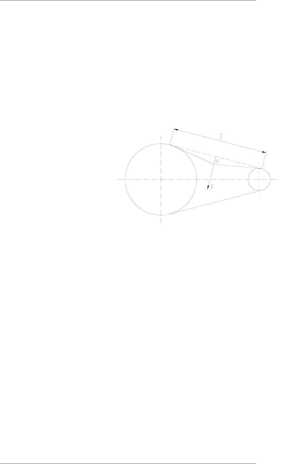
30 kW S-BAND/U ANTENNA GROUP
CORRECTIVE MAINTENANCE
6.11 Rev. C
6.2.3 Belt installation tension
The required level of pre-tension will lie between the maximum and minimum
values calculated from the formulae below.
As a general guide the lower level will be applicable to lightly loaded, smooth
running drives, whereas drives subjected to high shock loads or frequent starts
will be tensioned at the higher level.
Deflecting Force (F)
1 Maximum pre-tension
P x 50
F = -------- = 36.2 Kg
V
2 Minimum pre-tension
P x 25
F = --------- = 18.1 Kg
V
Belt deflection
S
d = ------- = 6.3mm
50
Where
S = Belt span (mm)
P = Transmitted power (KW)
V = Belt speed m/s
Note
Pitch x N x rpm
V = --------------------------- (m/s)
60000
N = Grooves on driver
Rpm = rpm of driver

30 kW S-BAND/U ANTENNA GROUP
PART LIST
7.1 Rev. C
CHAPTER 7
PART LIST
7.1 Introduction
This chapter provides the list of the 30 kW S-BAND/U Antenna Group
replaceable parts.
7.1.1 Part List
The parts list is divided into major assemblies. All parts attached to the
assemblies are listed in Part List Tables. The Parts List Tables consist of eight
columns as follows:
- Column 1: POS. (Position): the column reports the
replaceable parts position in the reference figure
- Column 2: DESCRIPTION: the column includes the
descriptive identification data of the replaceable part
- Column 3: DRAWING SPECIFICATION NUMBER OR TYPE:
the column reports the drawing specification number or the
type of the replaceable part assigned by the supplier
- Column 4: REQUIRED QUANTITY (N): the column indicates,
for each replaceable part, how many of them are assembled
on the equipment
7.1.2 Part Location Illustration
Figures from Chapter 9, Figure 9.1.35 to Figure 9.1.38 provide the location of
the components. The position numbers of items shown in the figure are
referenced in the related Parts List Tables.

30 kW S-BAND/U ANTENNA GROUP
PART LIST
7.2 Rev. C
7.2 Part list tables
Table 7.2.1 - List of Items Shown in Chapter 9, Figure 9.1.35
POS.
DESCRIPTION
DRAWING
SPECIFICATION
NUMBER OR TYPE
REQUIRED
QUANTITY
(N)
Ref 30 kW S-BAND/U Antenna Group Unit LSSGRP001 1
1 Parts List of the RTM 30S/U/D Unit 303770A1 1
2 Antenna Pedestal S/U Unit:
- Type 03R-039 303830A1 1
3 Performance Monitor Arm for Pedestal 03R-039 303813A1 1
Table 7.2.2 - Parts List of the RTM 30S/U/D Unit
(Figure 9.1.36)
POS.
DESCRIPTION
DRAWING
SPECIFICATION
NUMBER OR TYPE
REQUIRED
QUANTITY
(N)
1 POWER MOS Board 972551A3 1
2 RTM CONT B Board 972981A2 1
3 NIFB Assy 303186A2 1
4 Fuse 3.15A 250V DLY (F1) 54F010P020 1
5 Fuse 2A 250V DLY (F2) 54F010P018 1
6 LNFE Assy 302311A5 1
7 S Band Magnetron 89A505P020 1
8 Noise Generator Assy 302237A2 1
Table 7.2.3 - Parts List of the Antenna Pedestal S/U Unit Type 03R-039
(Figure 9.1.37 and Figure 9.1.38)
POS.
DESCRIPTION
DRAWING
SPECIFICATION
NUMBER OR TYPE
MOUNTED
QUANTITY
(N)
1 Motor Group 71M416P001 1
2 Rotating Joint 89A068P003 1
3 Gear Reduction Group 36G106P001 1
4 Driving Belt 36A004P010 1
5 Antenna Generator Disk 302660P002 1
6 Optical Read-out Board 972671A1 1
7 Flat Cable with 8 Wires 302445A1 1
8 Antsign Board 972661A1 1
9 Cable Assy with 7/16” Connector 56C034P003 1
10 3Φ Filter 302891A2 1

30 kW S-BAND/U ANTENNA GROUP
INSTALLATION
8.1 Rev. C
CHAPTER 8
INSTALLATION
S-band Antenna Group including 12 feet
Antenna and Pedestal with 30 kW
Transceiver upmast
TABLE OF CONTENTS
CHAPTER 8
INSTALLATION ......................................................................................................... 8.1
8.1 Introduction................................................................................................................. 8.2
8.1.1 Shipping.......................................................................................................................8.2
8.1.2 Unpacking....................................................................................................................8.2
8.1.3 Storage ........................................................................................................................8.3
8.1.4 Handling.......................................................................................................................8.3
8.2 Specifications ............................................................................................................. 8.3
8.2.1 Dimensions and weights (also see outline drawings) .................................................8.3
8.2.2 Required power ...........................................................................................................8.4
8.2.3 Environmental Data .....................................................................................................8.4
8.3 Installation................................................................................................................... 8.4
8.3.1 Installation Principles...................................................................................................8.4
8.3.2 Mechanical installation ................................................................................................8.6
8.3.2.1 Pedestal with transceiver ........................................................................................... 8.6
8.3.2.2 Antenna .................................................................................................................... 8.7
8.3.2.3 Safety Switch .............................................................................................................. 8.7
8.3.2.4 Performance Monitor Arm .......................................................................................... 8.8
8.3.3 Electrical installation ....................................................................................................8.8
8.3.3.1 Multicore Cable........................................................................................................... 8.8
8.3.3.2 Safety Switch .............................................................................................................. 8.9
8.3.3.3 Performance Monitor Arm .......................................................................................... 8.9
8.3.3.4 Grounding................................................................................................................... 8.9
8.3.3.5 Installation Check-out ............................................................................................... 8.10
8.3.4 Pre Setup Procedures ...............................................................................................8.10
8.3.4.1 Antenna Turning Motor power Voltage and Phase .................................................. 8.10
8.3.4.2 Head Line alignment procedure ............................................................................... 8.11
8.4 Installation figures and drawings .............................................................................. 8.12
8.5 Annex........................................................................................................................ 8.24

30 kW S-BAND/U ANTENNA GROUP
INSTALLATION
8.2 Rev. C
8.1 Introduction
This chapter of the Technical manual can be used as a self-contained
Installation Manual for the S-band Antenna Group including 12 feet Antenna
and Pedestal with 30 kW Transceiver upmast. It contains necessary
information, pictures and drawings to handle, assemble and install this unit as a
part of the complete Radar Equipment. Actions how to prepare this unit for the
Radar Equipment Setup Procedure are also described.
8.1.1 Shipping
Following general rules apply:
- Inspection for damage during transport
- When the unit(s) arrives at destination, inspection should be
performed immediately to register any damage that may
have occurred during transfer
- The customer is normally responsible for insurance during
the transportation. If any damage is found, both the
insurance company and the shipping agent must be
informed immediately
8.1.2 Unpacking
The unit parts are placed in cardboard boxes covered with a plastic sheet. Each
box includes a protecting polyurethane box shaped for the contained parts.
The following rules should be observed:
- Units must be transferred on board still packed into their
boxes
- When the units are removed from their boxes they must be
left in their protective plastic cover until installation
It is advisable to keep the packing material for possible future use the plastic
sheet in which the unit is wrapped can be used to protect it during installation
and maintenance procedures.
In addition to the various main parts forming the unit (see par. 8.3.2 below)
there is further materiel included in the delivery. Those additional things are:
- Technical Manual with Installation Manual included
- Installation Kit (Terminals, clamps, connectors etc.)
- Standard Spare Part Kit (Fuses etc.)
The Installation Kit and the Spare Part Kit is necessary for the installation and
operation of the equipment, and must be kept by them who perform the
installation work. Contents of the Kits should be checked immediately after
unpacking, using the materials list contained in the box. The Manufacturer will

30 kW S-BAND/U ANTENNA GROUP
INSTALLATION
8.3 Rev. C
not accept claims for missing items unless presented immediately after
unpacking.
8.1.3 Storage
After the material contained in the boxes has been inspected in the presence of
customer and it has been verified that no damage has occurred, the unit shall
be stored in its original packing until the time of installation. The storage
premises must be dry and well protected.
If the units must be kept in storage for more than one month, it is advisable to
insert hygroscope substances, such as silicon gel salts, in the crates. See par.
8.2 Specification, (Environmental Conditions)
8.1.4 Handling
The antenna and the pedestal must be run up the mast separately and then
assembled.
The pedestal with attached transceiver is lifted by crane. Use slings attached to
the four eyebolts fitted on top of the pedestal.
Minimum angle at the base is 60º. See Figure 1 (Lifting by crane)
The pedestal contains delicate electronic components - handle accordingly. The
antenna is also lifted by crane using its two eye-bolts. The antenna surface is
sensitive to impacts and pressure. Any deformation of the antenna surface can
reduce the radar performance.
8.2 Specifications
30kW S-Band/U Antenna Group
8.2.1 Dimensions and weights (also see outline drawings)
Length 959 mm
Width 481 mm
Height 1000 mm
Weight of pedestal with transceiver 165 Kg
Weight of antenna 90 Kg
Swing circle with 12 ft antenna 3700 mm

30 kW S-BAND/U ANTENNA GROUP
INSTALLATION
8.4 Rev. C
8.2.2 Required power
220/380 VAC, 3Φ, 50 Hz or
Alternatives
255/440 VAC, 3Φ, 60 Hz
Power consumption 4200 VA
8.2.3 Environmental Data
Operating temperature -25°C / +55°C
Storage temperature
-25°C / +70°C
Relative humidity Up to 95% at +40°
Water resistance, Salt spray, Vibrations
etc
as per IEC 60945
Wind resistance, relative wind 100 knots
8.3 Installation
30kW S-Band/U Antenna Group
8.3.1 Installation Principles
In order to obtain the best radar performance and accessibility, the following
precautions should be used:
- Space for the antenna to swing freely. See 8.2 above
(Specifications; Antenna)
- Safety and easy access for maintenance purposes. It is
preferable to use a platform with safety handrail. Figure 2
(Suggested Masthead mounting)
- The antenna to be accessible in all directions
- Avoid exposure to exhaust fumes from the funnel
- Avoid strong vibrations
- Avoid interference between two antennas
- Avoid obstacles in the radar beam, especially ahead of
athwartships directions
If two radar sets are installed, their antennas should be installed on different
levels.
The antennas can be mounted, either on a single mast construction, so they are
on top of each-other, as illustrated in Figure 2 (Suggested Masthead mounting),

30 kW S-BAND/U ANTENNA GROUP
INSTALLATION
8.5 Rev. C
or the antennas can be mounted on a platform, Figure 3 (Suggested Antenna
mounting), one on portside and one on starboard side.
The following formula and drawing, as illustrated in Figure 4 (Antenna Position),
will help you to determine the correct distance and height between the two radar
antennas. The 25° angle on the drawing is the actual vertical beam-width with a
safety margin included.
Example:
“H=L/3”,
H = height between the two antennas
L = the distance between the two antennas
If the distance L is 6m, then the height should be 6/3 = 2m.
Blind sectors towards the bow and within a few degrees on port and/or
starboard side caused by the structure of the ship must be avoided with great
care. In case of a blind sector at the bow in mid-ships’ position, it is advisable to
mount the antennas on the starboard side of the ships’ keel-line.
When obstacles are sufficiently far from the antenna, they will result in a blind
sector on the radar display with approximately the same amplitude as observed
by the human eye, but these obstacles can produce false echoes. An echo
produced by an obstacle close to the antenna, can be suppressed by reflecting
the antenna-beam skywards by mounting a reflector made of metal, as also
illustrated in Figure 2 (Suggested Masthead mounting). This solution however
does not eliminate the blind sector, but will reduce false echoes produced by
the obstacle. The best position for the reflector can be found by testing out
different positions.
It is highly recommended that the shipyard submit the drawings of the radar
antenna position(s) to the Manufacturer for approval.
The Installation consists of following basic steps:
- Mount the Antenna Pedestal without the antenna on the
mast
- Make relevant cable connections
- Install and connect the Performance Monitor arm
- Install the Safety Switch
- Mount the Antenna on the Antenna Pedestal

30 kW S-BAND/U ANTENNA GROUP
INSTALLATION
8.6 Rev. C
NOTE
Antenna pedestal should be installed in such way that the
performance monitor arm is not facing funnels or other big ship
obstruction. Sector blanking is enabled to prevent false echoes
caused by funnels and/or big ship construction (see above). If
performance monitor arm is positioned, within this blanking
area, the pedestal must be turned because the radar
performance monitor is not working where there is no
transmission in the sector of its sensor.
Installation of Safety Switch is compulsory. It is recommended to be installed at
the bottom of the stairs giving access to the Antenna Pedestal. The waterproof
switch is supplied by Manufacturer, but a connection cable (2x2,5mm2) should
be provided by the shipyard.
The Antenna Group must be covered by plastic sheet during any painting
performed after the installation.
NOTE
In no case, the Antenna Array should be used to hoist the
assembly up the mast.
8.3.2 Mechanical installation
The S-band/U Antenna Group consists of following units and type designations:
Pedestal with transceiver 03R039 with 09N-011
12 feet antenna 02R-039B
Performance monitor arm 303813A1
Safety switch 74X376P001
8.3.2.1 Pedestal with transceiver
Prepare the platform for mounting of the pedestal, with its transceiver. Hole
diameters and distances are evident from drawing: Figure 5 (Dimension
Drawing).
The pedestal should be mounted with the transceiver unit pointed astern.
However the antenna swinging plane must be horizontal in all directions when
ship is upright on even keel. Consider giving ample space for service, especially
astern of the antenna group. If such space can not be achieved, contact
Manufacturer for installation alternatives.

30 kW S-BAND/U ANTENNA GROUP
INSTALLATION
8.7 Rev. C
NOTE
The plastic protection cover on the pedestal rotary joint must
not be removed until just before mounting the antenna. Anyhow
the rotary joint must not be left uncovered when the antenna is
not mounted
NOTE
The fixing materials to fasten the antenna pedestal to the ship’s
platform are not provided by the manufacturer. Assuming a
platform plate thickness of 20 mm, four M20 stainless steel
bolts of 80 mm length, with relative nuts grooves and washers,
must be used. The tightening couple is 256 Nm
8.3.2.2 Antenna
The antenna and the pedestal must be run up the mast separately and then
assembled.
The installation procedure of the antenna with fixed coax cable to the antenna
pedestal consists of the following steps:
- Remove the bolts from the Antenna shaft, which will be used
to fasten the Antenna (Antenna Support) to the Pedestal
- The Antenna must be lifted in the mounted eye-bolts. Also
see 8.1.4 above, Handling
- With the antenna hoisted, lay it on the pedestal matching the
six leading bolts with the relevant
- wholes, taking care that the front of the antenna is orientated
at the same direction as the arrow on the antenna shaft
- Tighten all antenna attaching bolts. The tightening couple is
130Nm
- Insert the 90 degrees connector of the antenna coax cable
on the rotary joint connector and secure it by fastening the
attaching ring
8.3.2.3 Safety Switch
Installation of safety switch is compulsory. The safety switch is supplied by the
Manufacturer.
It is recommended to place the safety switch at the bottom of the stairs that are
giving access to the radar mast. The switch must be mounted with the cable
glands pointing down. Connect the cable as described in 8.3.3 below Electrical
installation.

30 kW S-BAND/U ANTENNA GROUP
INSTALLATION
8.8 Rev. C
8.3.2.4 Performance Monitor Arm
To install the P.M. Arm proceed as follows:
- Open the cover of the pedestal
- Remove the 4 screws securing the small plate on the
Antenna Pedestal
- Install the O-ring on the fixing plate of the P.M. ARM
- Draw the cable from the PM-arm through the supporting
plastic pipe and through the hole in the cast wall over the
antenna generator disk as evident from Figure 9 (Pedestal)
- Mount the PM-arm angled upwards
- Connect cable as described in 8.3.3 below Electrical
installation
8.3.3 Electrical installation
The electrical installation in the 30 kW S-Band/U Antenna Group consists or
cabling and connection to terminals, Figure 6 (Terminals Drawing), as described
below.
8.3.3.1 Multicore Cable
Also see Annex 8.5.1 Multicore Cabling and Termination Principles.
NOTE
Use the installation materials for the Multicore cable which are
delivered by the manufacturer to ensure proper connection
Normally the cable (16 core+3 Coax), P/N 55M45455P002(3), is delivered to a
length of 60m. The Multicore cable includes wires for Power, Video, Trigger and
Antenna data. It shall be used for connection between the Antenna Group and
the External S-Band PSU, as well as for connection between the External S-
Band PSU and the display/interswitch unit. It is required to handle this cable
with particular care.
The Antenna end of the multi-core cable shall be connected to :
- TB 9&10 and J1/J3 on the RTM Control B Board in the
transceiver and according to separate system drawings
relevant to the application of the 30 kW S-Band/U Antenna
Group. Also see Figure 7 (Cabling) and Figure 8 (Control B
board Drawing)

30 kW S-BAND/U ANTENNA GROUP
INSTALLATION
8.9 Rev. C
- TB Filter at the inside bottom of the pedestal chassi, Figure
9 (Pedestal), for the 3 phase motor power cores
- TB 1 at the inside left bottom of the transceiver chassi,
according to system drawings relevant to the application of
the 30kW S-Band/U Antenna Group
Terminals, clamps and connectors etc. included in the Installation Kit must be
used. Content of the installation Kit can vary depending on the Application of
the 30kW S-Band Antenna Group. E.g. if Multicore cable is already terminated
in factory corresponding parts are excluded.
For the termination of the Multicore Cable in the External S-Band PSU see
Installation Manual for that unit.
8.3.3.2 Safety Switch
The safety switch is supplied by the Manufacturer. Cable from the switch
(normally placed at bottom of Radar Antenna mast) to the Transceiver unit is
not included.
- Check the Safety Switch is placed as described in par. 8.3.2
(Manual Installation)
- Connect the two poles of the safety switch, Figure 10 (Safety
Switch), to TB1 SF/SFR placed down left at the inside of the
transceiver chassis (see Figure 7 (Cabling)).
- The cable gland not used must be properly sealed
- Carefully make sure that the switch is closed in “I” (On)
position and open in “0” (Off) position.
8.3.3.3 Performance Monitor Arm
- Open the cover of the pedestal
- After mounting the PM-Arm as described in 8.3.2 above
connect the PM-Arm cable to the plug and put it in the
socket at TB1 RM/RM05 on the ANT.SIGN.PCB. placed at
the inside bottom of the pedestal chassis. Figure 9
(Pedestal)
8.3.3.4 Grounding
Connect a tinned braided copper wire (>25mm2) between the Ground Terminal
on the Antenna Pedestal and the radar mast.

30 kW S-BAND/U ANTENNA GROUP
INSTALLATION
8.10 Rev. C
8.3.3.5 Installation Check-out
After wiring connections, before closing the antenna pedestal following
procedures and controls must be carried out to prevent any failure due to
incorrect installation.
- Clean the circuit boards with an antistatic brush
- Use a vacuum cleaner to remove any possible particles
from the cabinets
- Check for proper cable bends to assure a proper amount of
slack
- Check that ground connections are dully tightened as well
as terminal connections on the terminal boards
- Check if cable glands have a firm grip around the cables
8.3.4 Pre Setup Procedures
This paragraph provides information concerning the preliminary controls and
procedures to be performed as a completion of the electrical installation and
before supplying the unit with power and before performing the System Setup
Procedure:
NOTE
Powering the Radar System is not included in the Pre Setup
Procedure
- Carry out a careful visual inspection of the installed
components referring to the layouts of the unit and to the
interconnection drawings
- Carefully check the integrity of the fuses
- Check that the switches S1 and S2 on the transceiver
Control B board are in position “0”
NOTE
Following items must be thoroughly checked:
8.3.4.1 Antenna Turning Motor power Voltage and Phase
Check inside the Antenna Turning Motor junction box that the Star or Delta
configuration corresponds to the used 3 phase ship main power and frequency,
as described below:
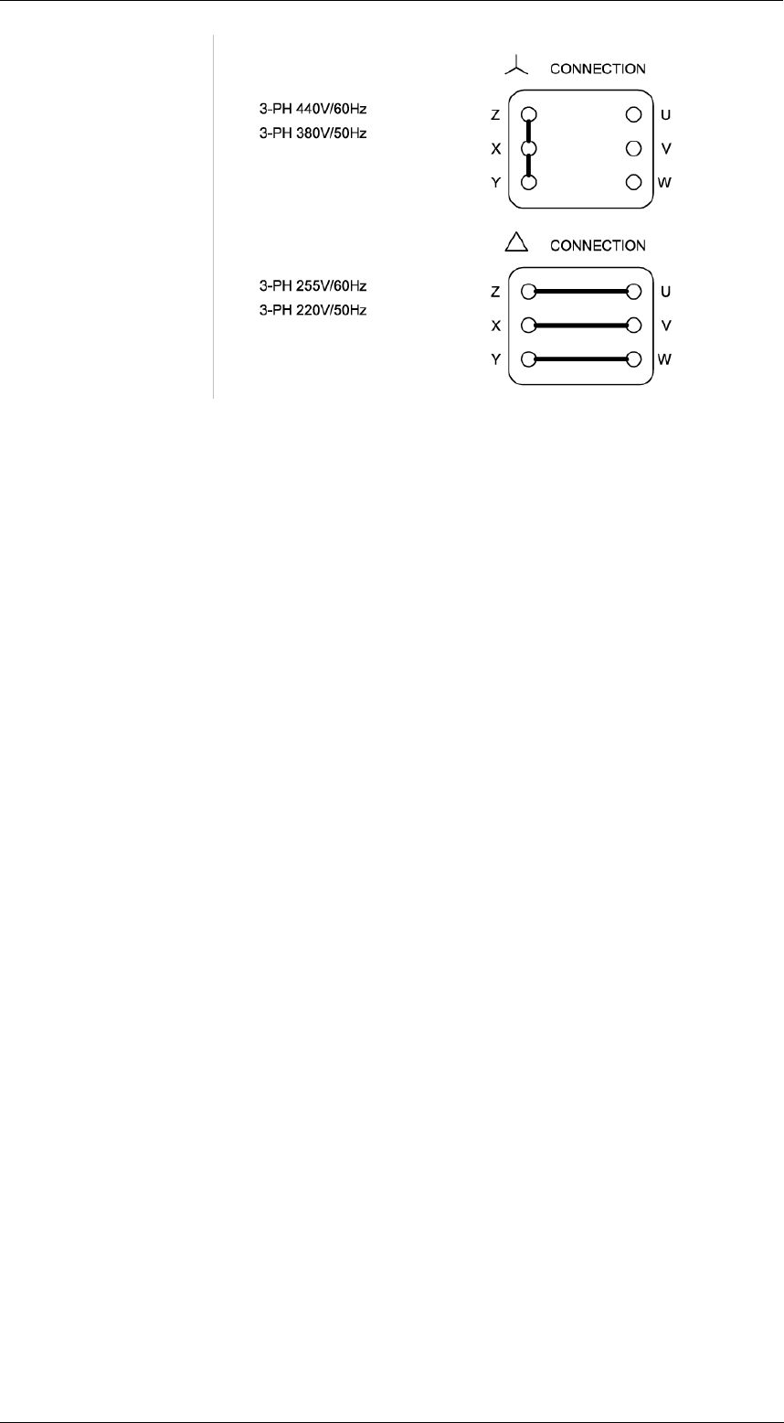
30 kW S-BAND/U ANTENNA GROUP
INSTALLATION
8.11 Rev. C
Also check that TB 3 in the External S-Band PSU is configured for same power
(see separate manual).
8.3.4.2 Head Line alignment procedure
If the equipment is not equipped with a 360 degree software adjustment, a
course alignment of the radar headline should be carried out as follows before
the final set up procedure.
- Turn the Radar main switch off and, to make sure that the
Antenna Motor can not be started, switch the Safety Switch
Off (0)
- Remove one Pedestal side cover by loosing the 4 fixing
bolts
- By using the proper Allen Keys (hexagonal keys), loosen the
six screws fixing the Antenna Generator Disk to the Belt
Pulley.
- Rotate the Antenna by hand to athwartship position to align
the Antenna Beam with the ship’s bow
- Rotate the Antenna Generator Disk until the bow indication
on the disk (the deeper slot) is in the Optical Read-out unit
gap. Figure 9 (Pedestal)
- Tighten the six hexagonal screws fixing the Antenna
Generator Disk
- Remount the cover of the Antenna Pedestal
- Turn the Safety Switch to position On (I)

30 kW S-BAND/U ANTENNA GROUP
INSTALLATION
8.12 Rev. C
8.4 Installation figures and drawings
The following figures and drawings are included after this page:
Figure 1 (Lifting by crane)
Figure 2 (Suggested Masthead mounting)
Figure 3 (Suggested Antenna mounting)
Figure 4 (Antenna Position)
Figure 5 (Dimension Drawing)
Figure 6 (Terminals Drawing)
Figure 7 (Cabling)
Figure 8 (Control B board Drawing)
Figure 9 (Pedestal)
Figure 10 (Safety Switch)
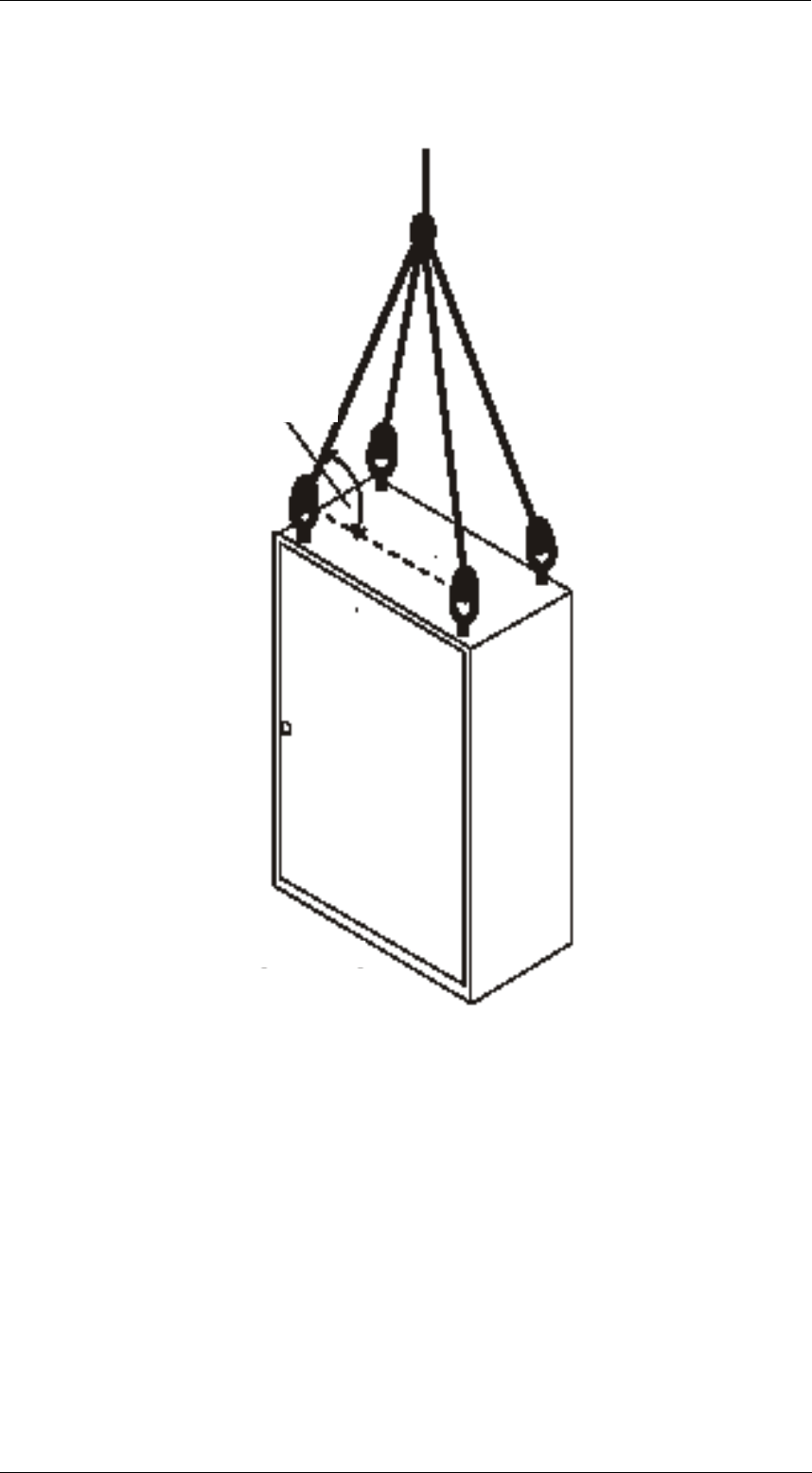
30 kW S-BAND/U ANTENNA GROUP
INSTALLATION
8.13 Rev. C
Fig 1 Lifting by crane
WARNING Never pass or stay under any lifted object.
>60°
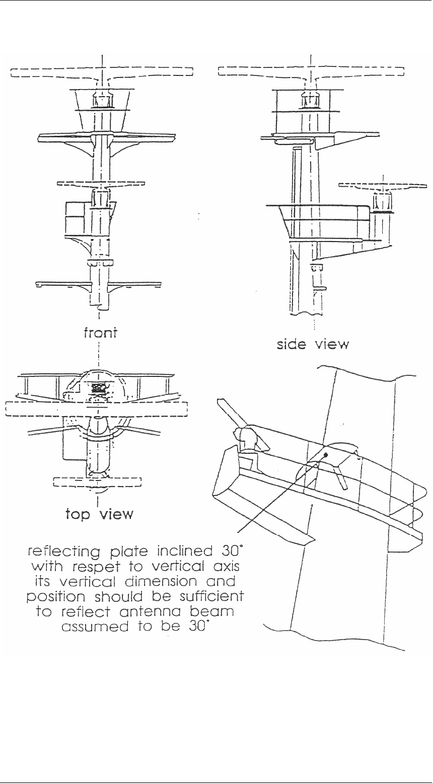
30 kW S-BAND/U ANTENNA GROUP
INSTALLATION
8.14 Rev. C
Fig 2 Suggested Masthead Antenna mounting
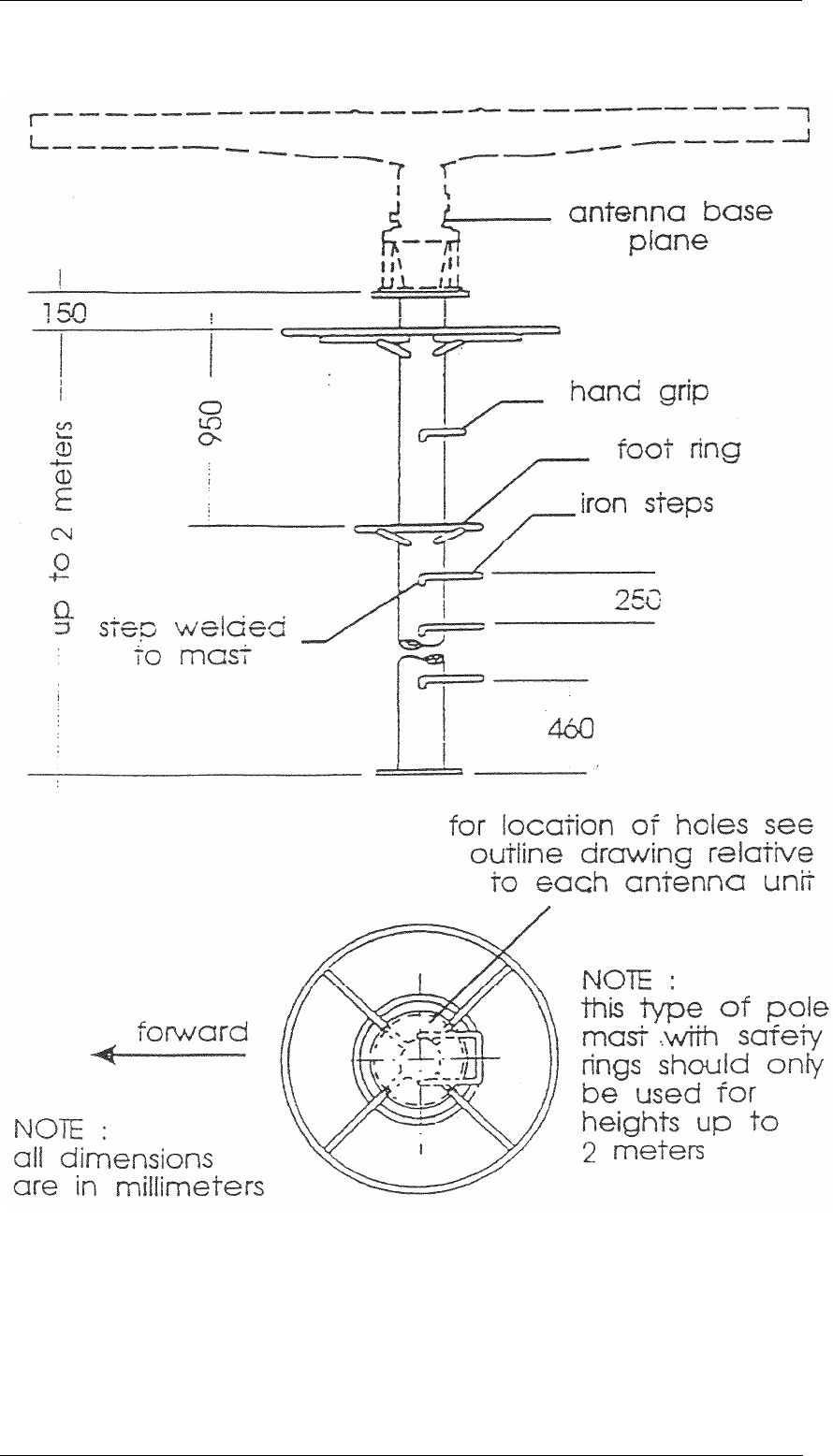
30 kW S-BAND/U ANTENNA GROUP
INSTALLATION
8.15 Rev. C
Fig 3 Suggested Antenna mounting
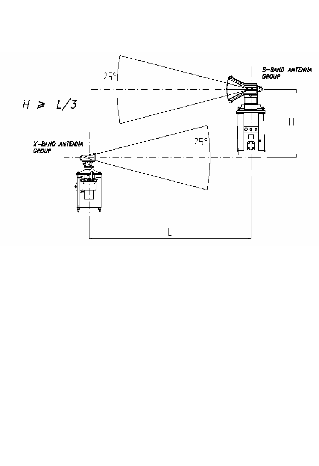
30 kW S-BAND/U ANTENNA GROUP
INSTALLATION
8.16 Rev. C
Fig 4 Atenna positions
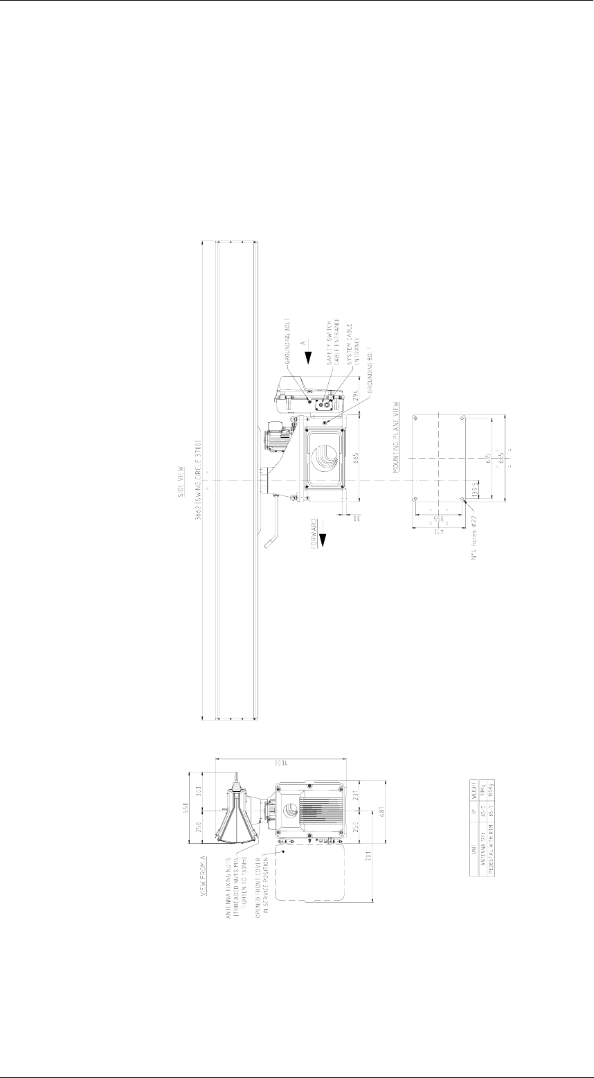
30 kW S-BAND/U ANTENNA GROUP
INSTALLATION
8.17 Rev. C
Fig 5 Dimension drawing
All dimensions are in mm
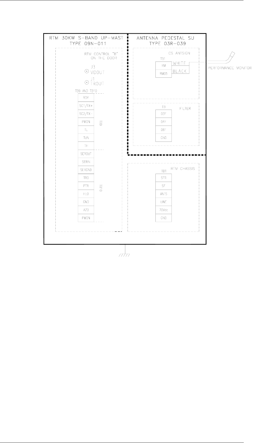
30 kW S-BAND/U ANTENNA GROUP
INSTALLATION
8.18 Rev. C
Fig 6 Terminals drawing
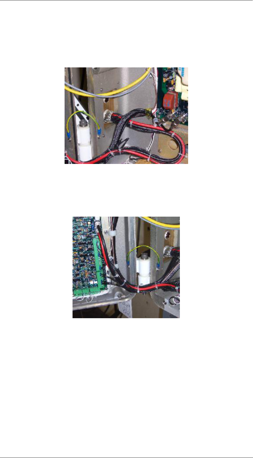
30 kW S-BAND/U ANTENNA GROUP
INSTALLATION
8.19 Rev. C
Fig 7 Cabling
30kW S-Band/U Antenna Group
Fix the cable inside the unit:
A
Route the cable inside the unit following the existing cabling to obtain free
installation when closing the door.
Connect the cables on the terminal boards on the RTM control-B:
B

30 kW S-BAND/U ANTENNA GROUP
INSTALLATION
8.20 Rev. C
Verify that you have free installation when closing the door:
C
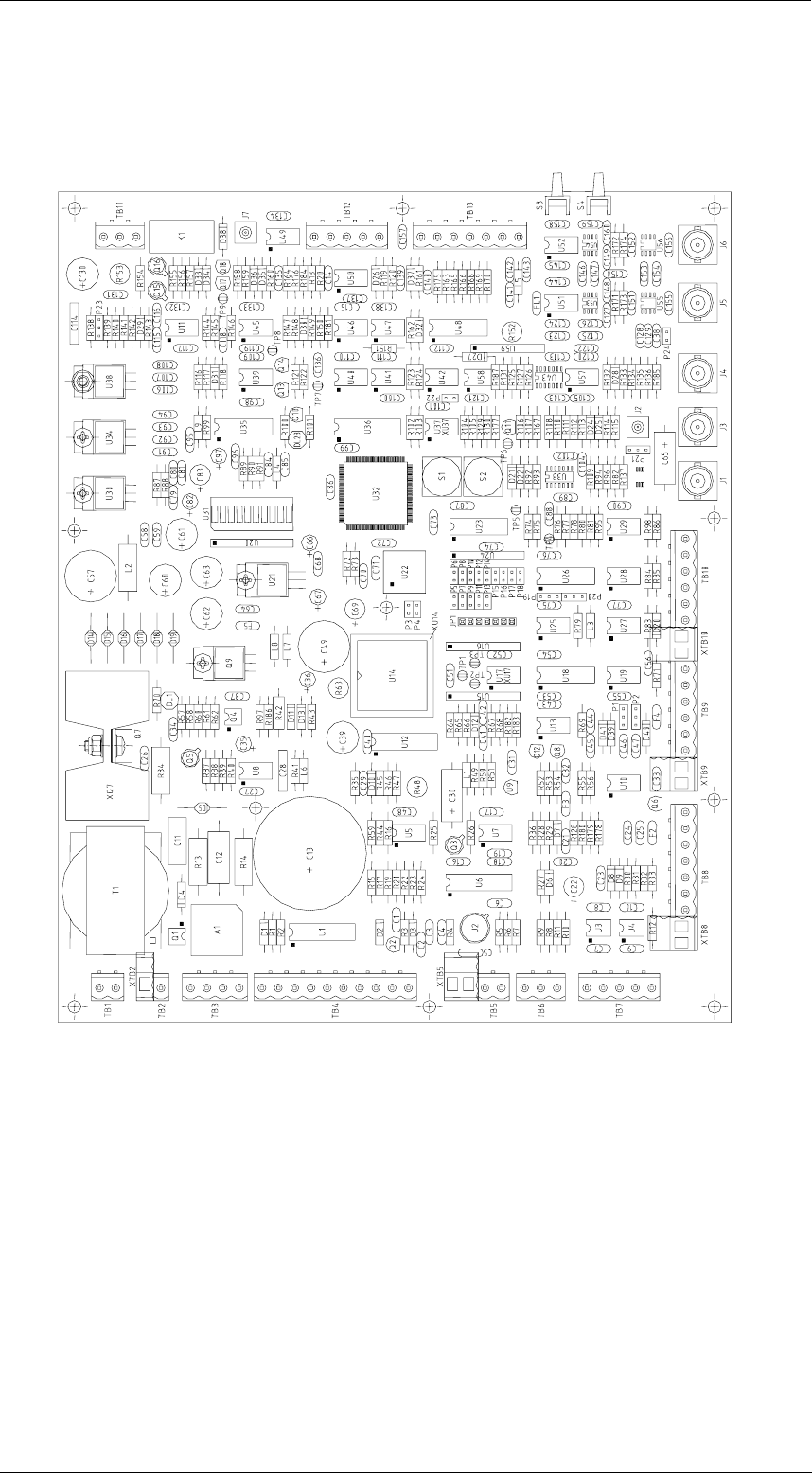
30 kW S-BAND/U ANTENNA GROUP
INSTALLATION
8.21 Rev. C
Fig 8 Control B Board
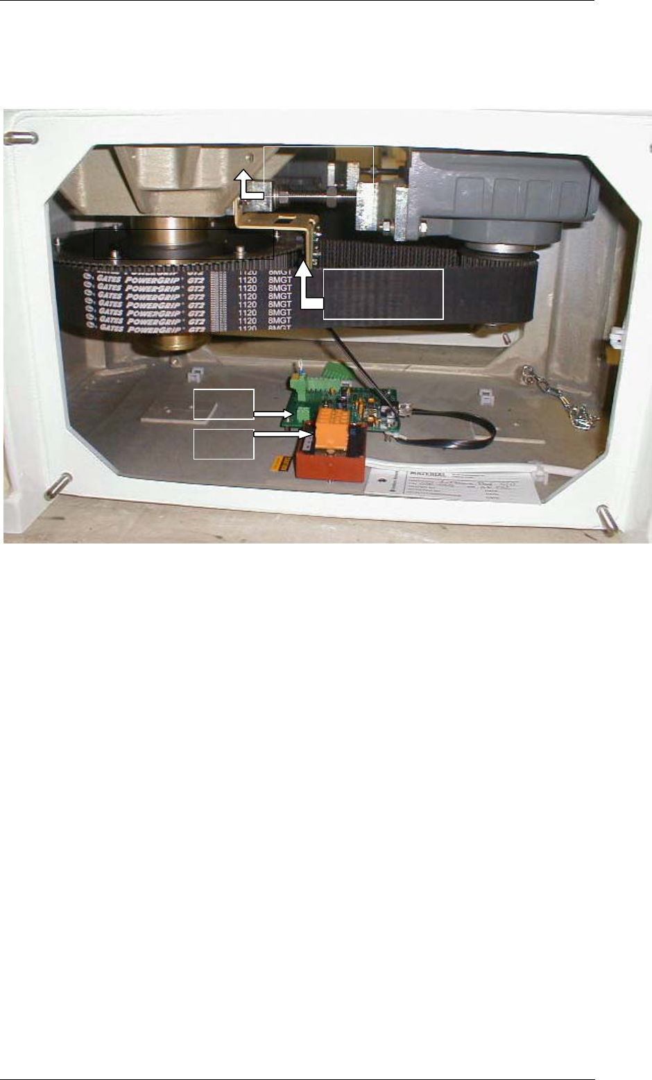
30 kW S-BAND/U ANTENNA GROUP
INSTALLATION
8.22 Rev. C
Fig 9 Pedestal
Antenna Pedestal TB1: PM-Arm
TB Antenna motor 3 Phase Main Power
OPTICALRE
AD-OUT
GENERATOR DISK
TB 1
TB
PM-CABLE
HOLE1
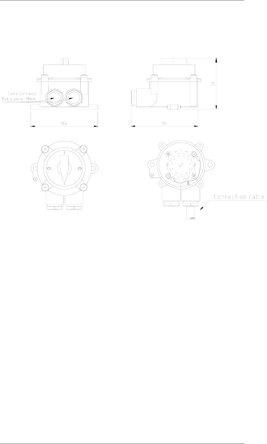
30 kW S-BAND/U ANTENNA GROUP
INSTALLATION
8.23 Rev. C
Fig 10 Safety Switch
All dimensions are in mm

30 kW S-BAND/U ANTENNA GROUP
INSTALLATION
8.24 Rev. C
8.5 Annex
Special extensive illustrated instructions are included in this paragraph
8.5.1 Multicore Cabling and Termination
Principles

30 kW S-BAND/U ANTENNA GROUP
ANNEX
1 Rev. C
55M455P002(3)
MULTI CORE CABLING
AND TERMINATION PRINCIPLES
FOR
• X-Band Antenna Group including 6 or 9 feet Antenna and Pedestal with
25 kW Transceiver upmast
• X-Band Antenna Group including 6 or 9 feet Antenna and Pedestal with
12 kW Transceiver upmast
• 30kW S-Band Transceiver downmast excluding Power Supply Unit
• S-Band Antenna Group including 12 feet Antenna and Pedestal with 30
kW Transceiver upmast
• External Power Supply Unit for S-Band Transceiver
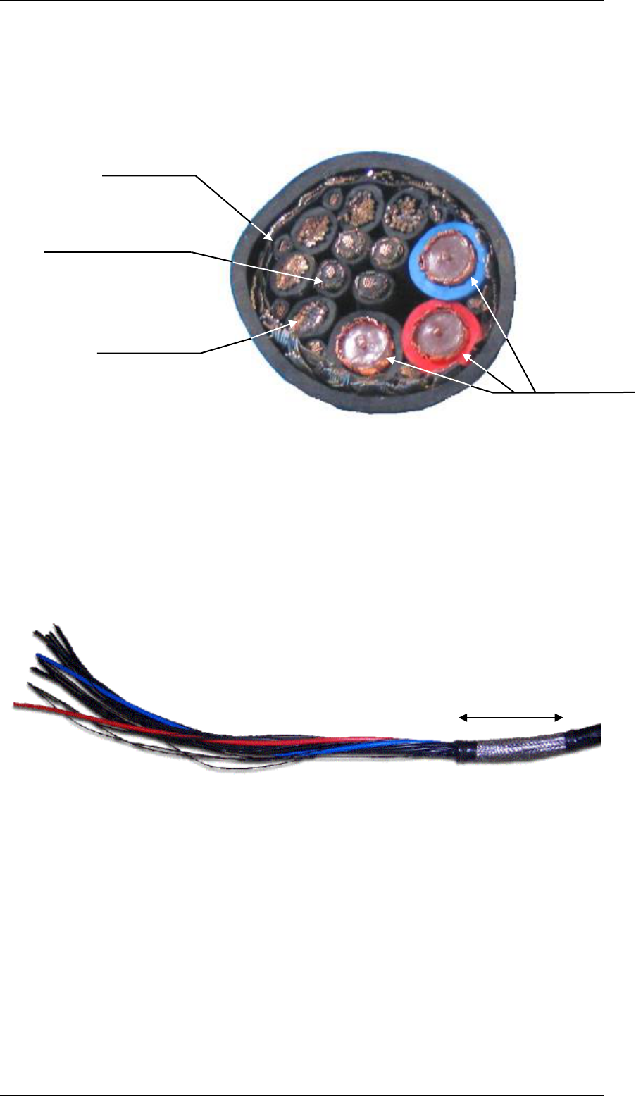
30 kW S-BAND/U ANTENNA GROUP
ANNEX
2 Rev. C
Installation Instructions
Multicore Cable Technical Specification
Core overview of Multicore Cable:
Cable handling
Dismantle the outer isolation of the cable for 70 cm, however in case of 12 or 25
kW X-Band/U Antenna Group the length must be 180 cm.
Remove most of the shield, let it be 5 cm with shield perceptive to vision:
7x0.50mm2
4x0.50mm2 shielded
Cores from 6 to 9 marked
also on the inner core
5x4.50mm2
Cores from 1 to 5
3xRG59
Blue
Red
Black
5 cm. remaining
shield

30 kW S-BAND/U ANTENNA GROUP
ANNEX
3 Rev. C
Main Shield and inner shields handling
Take back the shield:
Dismantle the outer isolation of the 0.5 mmq shielded cable. (Let it remain 4 cm
with isolated shielded cable).
Open the shield near the outer isolation, and pull out the centre cable without
cutting the shield:
Insert the shields from the inner cables into the main cable shield and take back
the shields:
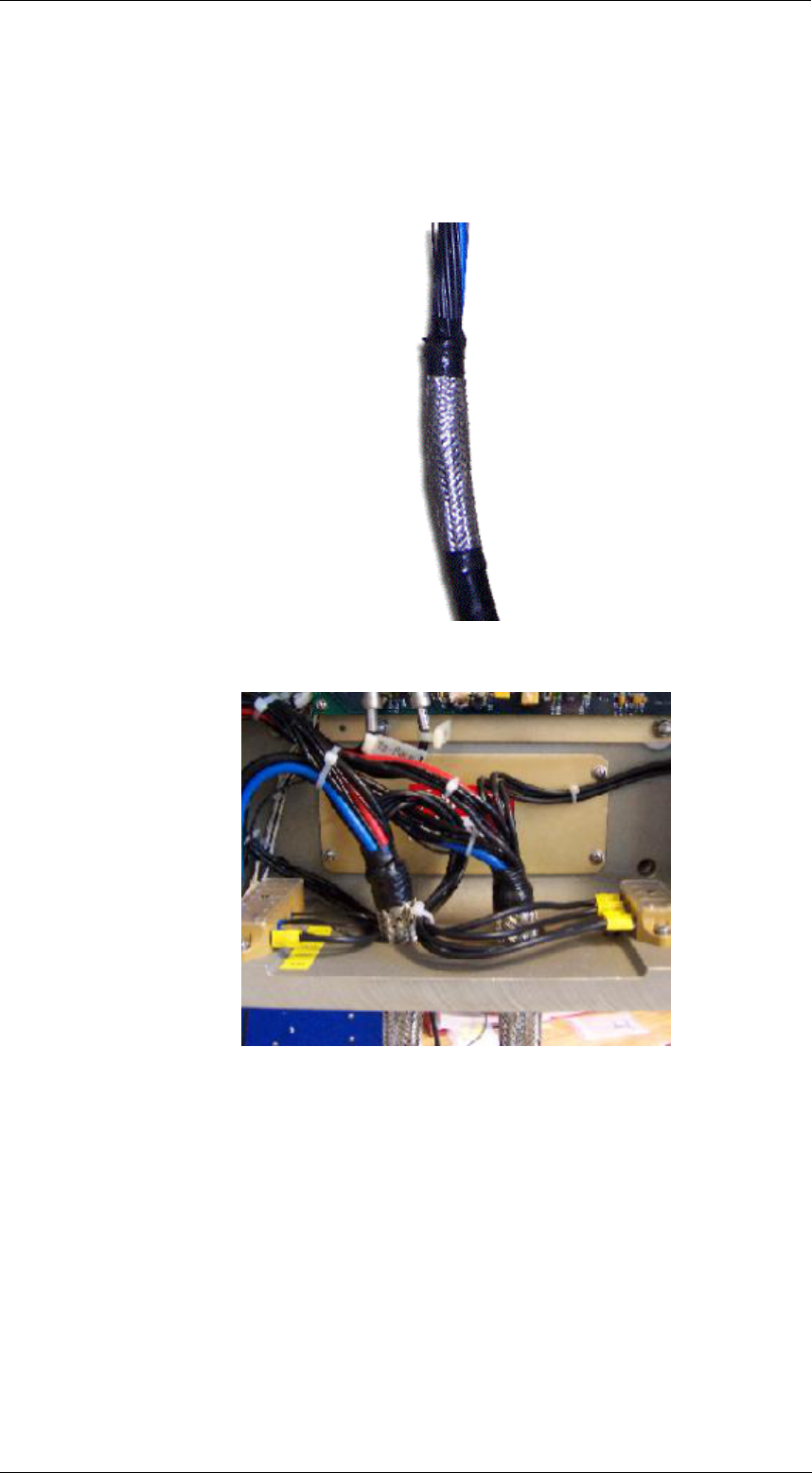
30 kW S-BAND/U ANTENNA GROUP
ANNEX
4 Rev. C
Cable Holder installation
See below, the correct procedure for installation of cable, in to the cable holder.
Refer to the “Main Shield and inner shields handling” for shields handling.
Fix the shields with tape:
Insert the cable in the unit, and fix the cable to the cable holder
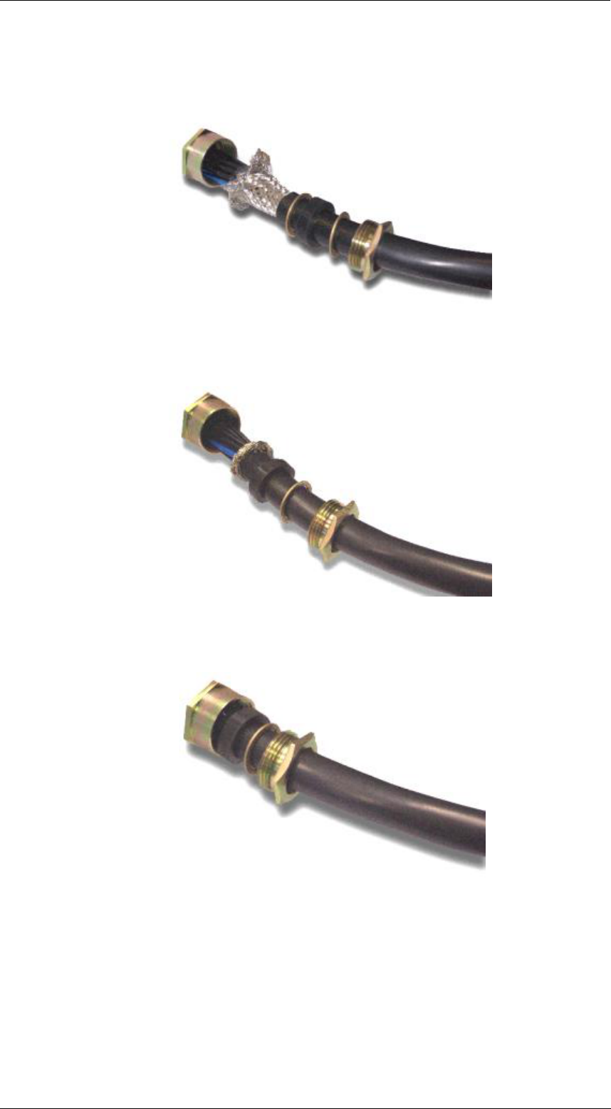
30 kW S-BAND/U ANTENNA GROUP
ANNEX
5 Rev. C
Cable Gland Installation
See below, the correct procedure for installation of cable, in to the cable gland:
Pass the wires trough the cable gland:
Refer to “Main Shield and inner shields handling” section, for shields handling.
Turn the shields over the first metal ring, and trim exceeding shields:
Insert the cable with all parts in to the cable gland:

30 kW S-BAND/U ANTENNA GROUP
ANNEX
6 Rev. C
After that, tight it hard, and be sure that the shield will remain inside the cable
gland:
Put some silicon compound, in the remaining space between the cable gland
bolt and the cable.
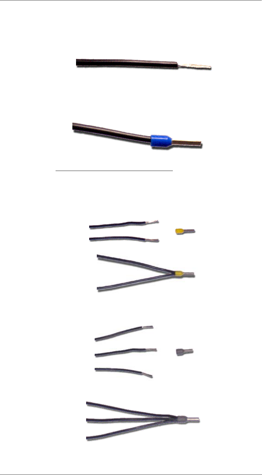
30 kW S-BAND/U ANTENNA GROUP
ANNEX
7 Rev. C
0.5 mmq cores
Cut the core to the wanted length and dismantle the core for 10mm:
Insert and crimp the blue-end terminal:
Note: End terminal should always be used.
Double connection in one terminal (yellow terminal):
Triple connection in one terminal (grey terminal):
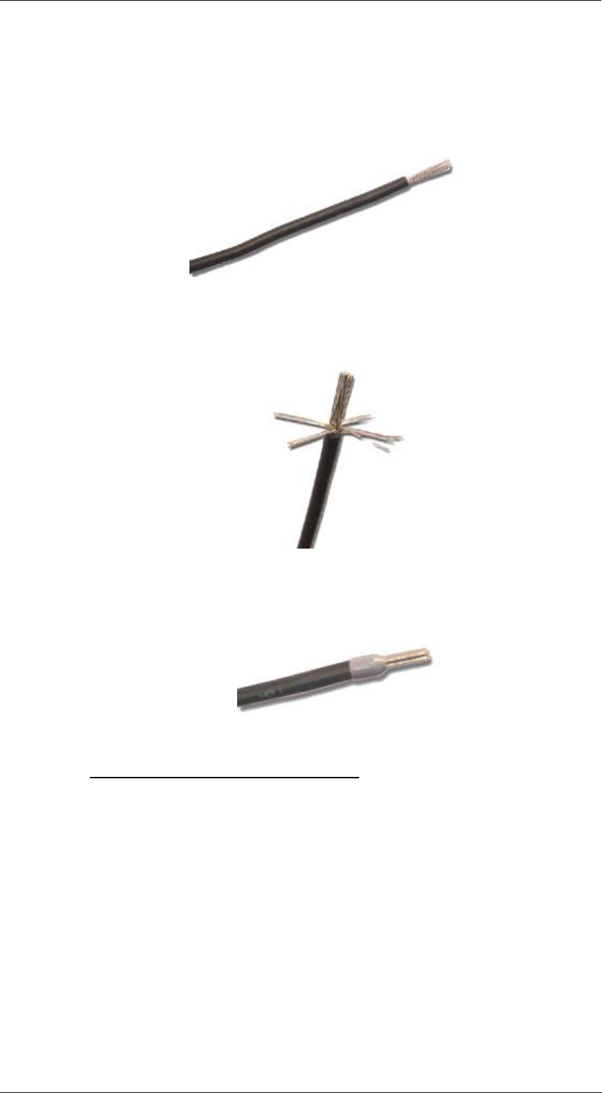
30 kW S-BAND/U ANTENNA GROUP
ANNEX
8 Rev. C
4.5 mmq cores
Cut the core to the wanted length and dismantle the core for 10mm:
Cut-out a few conductors in order to make easy the insertion of the grey-end
terminal:
Insert and crimp the grey-end terminal:
Note: End terminal should always be used.
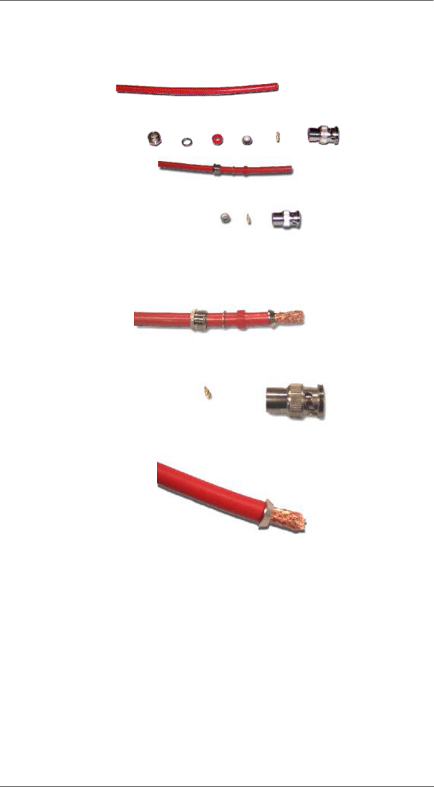
30 kW S-BAND/U ANTENNA GROUP
ANNEX
9 Rev. C
RG coaxial cables
Mechanical details of BNC connector:
Cut the cable to the wanted length.
Dismantle the outer isolation of the RG coaxial cable without damaging the
shield, and put the related part of the BNC connector as below:
Details related to the ring of the BNC connector.
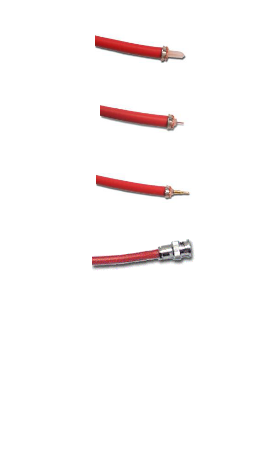
30 kW S-BAND/U ANTENNA GROUP
ANNEX
10 Rev. C
Take back the shield on the ring and trim exceeding shield:
Dismantle the outer isolation of the centre core without damaging the centre
core and be sure that the shield is not shorted with the centre core:
Solder the centre core with the BNC pin.
Be careful not damage the isolation (i.e. burned) during the solder process:
Mount the BNC connector as below:
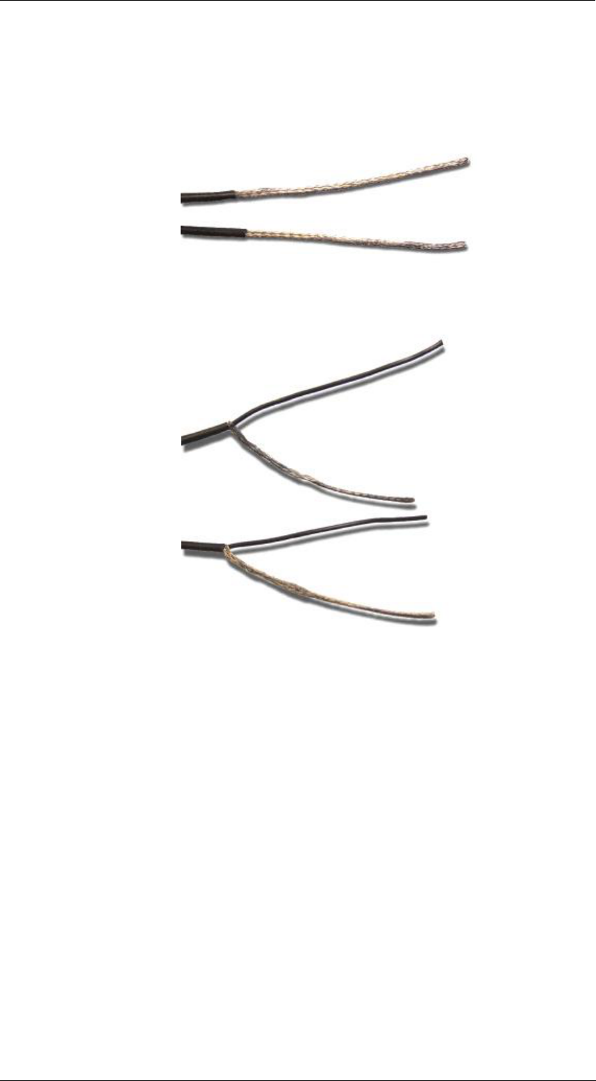
30 kW S-BAND/U ANTENNA GROUP
ANNEX
11 Rev. C
Shielded conductors
Cut the cable to the wanted length.
Dismantle the outer isolation of the 0.5 mmq shielded cable. (Let it remain 4 cm
with isolated shielded cable):
Open the shield near the outer isolation, and pull out the centre cable without
cutting the shield:
Refer to the “Main Shield and inner shields handling” for shields handling.

30 kW S-BAND/U ANTENNA GROUP
FIGURES
9.1 Rev. C
CHAPTER 9
FIGURES