Consilium Marine US SRT12002 12K WATT X-BAND MARINE RADAR User Manual 304202P003 Rev C
Consilium Marine US Inc. 12K WATT X-BAND MARINE RADAR 304202P003 Rev C
Contents
- 1. Technical Manual 1
- 2. Technical Manual 2
Technical Manual 2
SRT X-BAND RADAR SYSTEMS
ANNEX
304202P003 15 Rev. C
4.1.6 Grounding
The grounding point is designed to provide electrical contact between the outer
conductor of the elliptical waveguide and the ship’s ground.
The waveguide should be grounded along the vertical run near the Antenna
Group.
A section of the cable jacket is removed and the ground strap tightly fastened to
the outer conductor. The connection is then wrapped in butyl rubber tape and
vinyl tape for protection from weather. Finally, a terminal is attached to the
ground wire. The terminal should be connected to the ship’s ground terminal
board.
Do not make bends closer to the grounding point to prevent damage during the
hoisting.
4.2 Elliptical Waveguide Connectors
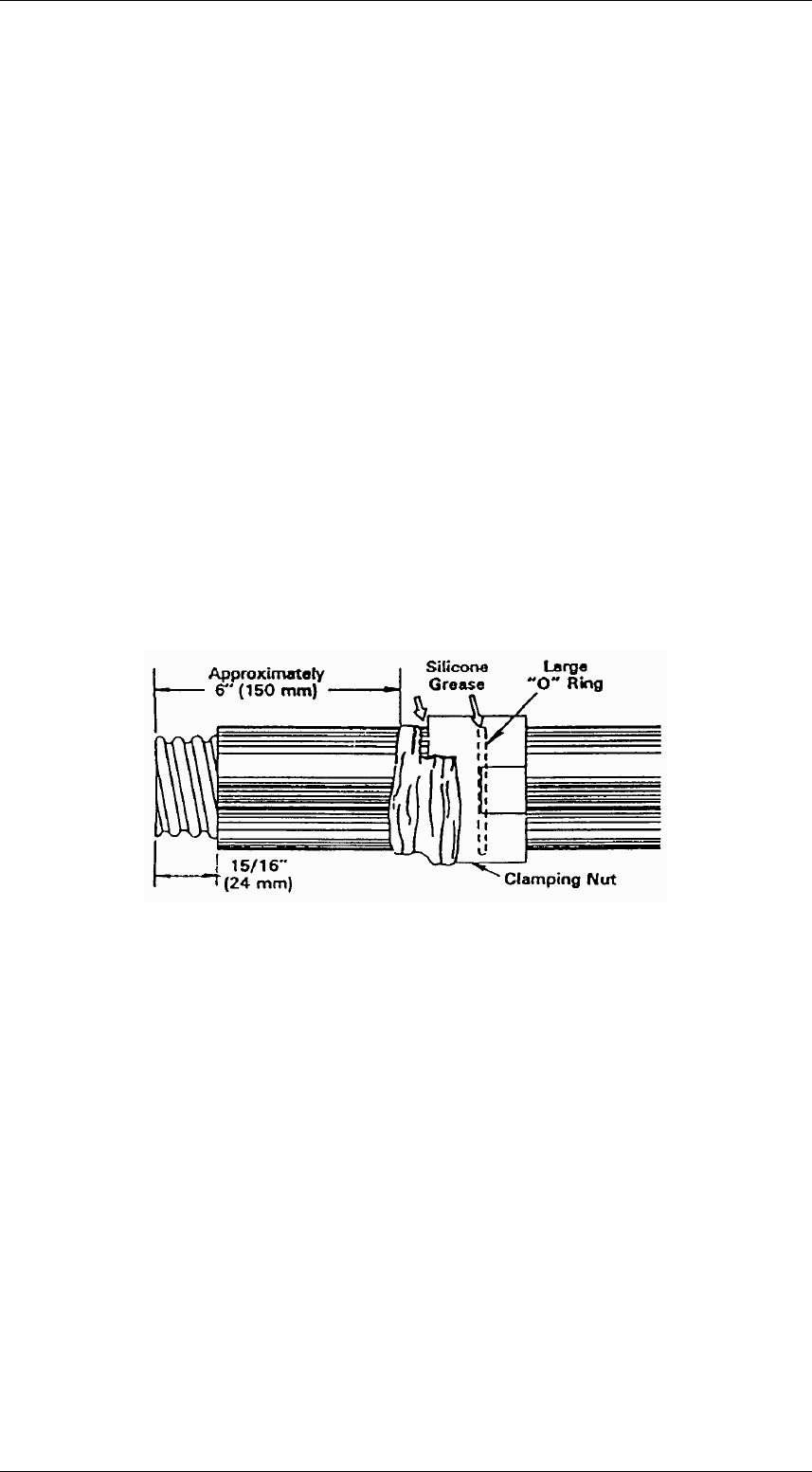
STEP 1 - Prepare waveguide as shown in Figure 1. End of waveguide must be
square. Use straight-edged piece of paper wrapped around waveguide
downward while cutting to keep copper chips from entering. Remove all burrs
from cut and of waveguide using knife and file. Clean exposed copper with
solvent. Clean inside of waveguide with bottle brush.
Figure 1:
STEP 2 - Add thin coating of silicone grease to large "O" ring gasket and place
it into groove inside clamping nut, then apply thin coating of silicone grease to
smooth inside surface of clamping nut that slides over smaller "O" ring (step 8).
Place nut over end of waveguide at distance from end as shown. Secure nut to
waveguide with several turns of tape covering end of nut to keep foreign matter
from entering during assembly operation.
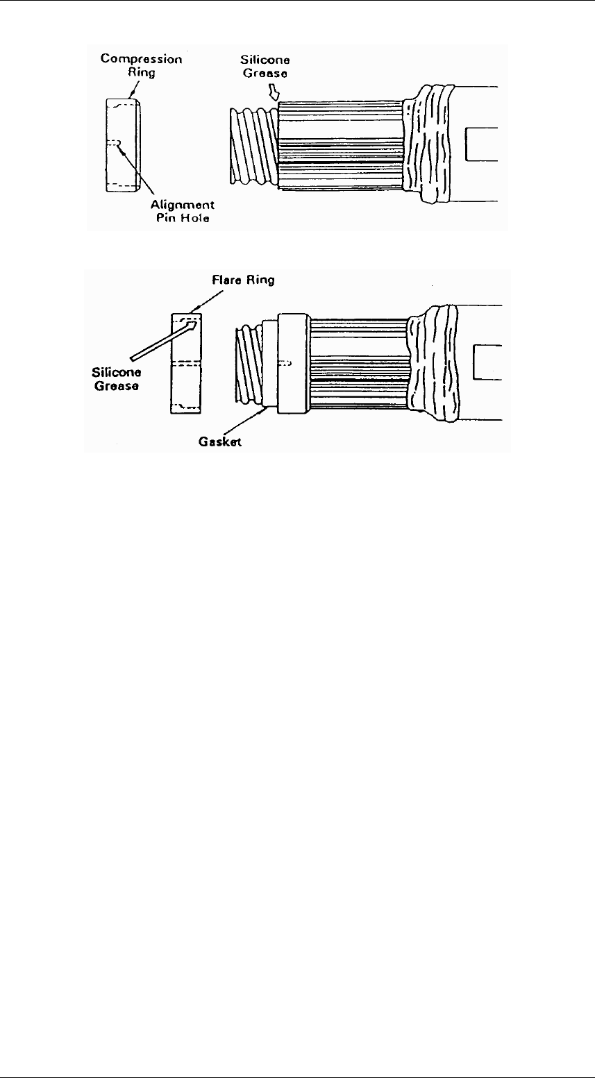
STEP 3 - Slip compression ring over waveguide until recessed edge bottoms
against jacket. Apply small amount of silicone grease to edge of jacket to aid in
installing compression ring. Alignment pin hole openings must face away from
waveguide as shown in Figures 2 and 3.
SRT X-BAND RADAR SYSTEMS
ANNEX
304202P003 16 Rev. C
Figure 2:
Figure 3:
STEP 4 - Turn gasket inside out and place over end of waveguide. Apply very
thin of coating silicone grease to gasket threads, the flip gasket over and
against compression ring. Apply thin coating of silicone grease to outside
surface of gasket. Refer to Figure 3. Clean any silicone grease from exposed
copper using solvent.
STEP 5 - Slip recessed side of flare ring over gasket.
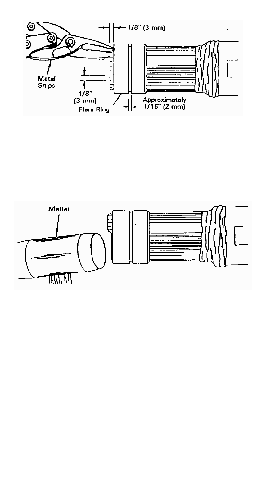
Alignment pin holes in flare ring and compression ring must be in line. Flare ring
must be pushed against compression ring as tight as possible. refer to Figure 3
and 4. Approximate opening between flare ring and compression ring should be
as shown.
STEP 6 - Use metal snips to make cuts into end of waveguide to depth and
intervals shown to form tabs. See Figure 4. Make cuts as close as possible to
flare ring.
SRT X-BAND RADAR SYSTEMS
ANNEX
304202P003 17 Rev. C
Figure 4:
STEP 7 - Flatten tabs against flare ring. Use mallet as shown figure 5. Use only
enough force to flatten tabs. Do not strike tabs so hard as to reduce thickness of
metal. Trim any tab that protrudes past outside of groove in flare ring. After tabs
are flattened and trimmed, tabs should be cleaned with solvent to remove any
silicone grease. Face off connector body with contacts tabs should also be
cleaned thoroughly so that no grease is present in mating RF contact surfaces.
Clean inside of waveguide with bottle brush.
Figure 5:
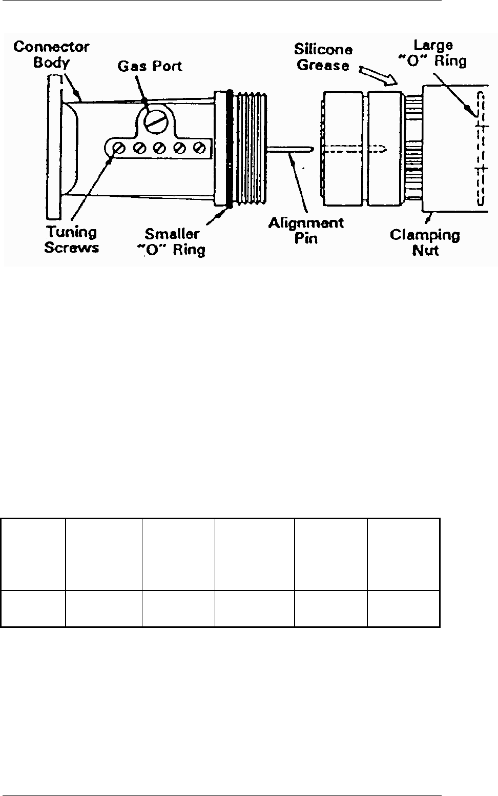
STEP 8 - Please smaller "O" ring gasket into groove in connector body. Do not
apply silicon grease to this gasket. Apply thin coating of silicon grease to rear
outer surface of compression ring. This will allow large "O" ring gasket inside
clamping nut to slide over compression ring.
STEP 9 - Refer to figure 6. Place connector body against flare ring. Alignment
pins must be properly seated in alignment holes of flare ring and compression
ring.
Untape and slide clamping nut over assembled part and screw it onto connector
body. Tighten connection with wrenches. Use adjustable wrench on rectangular
portion of connector body to hold it in position while clamping nut is tightened.
Turn clamping nut only; Do not turn connector body.
SRT X-BAND RADAR SYSTEMS
ANNEX
304202P003 18 Rev. C
Figure 6:
STEP 10 - Waveguide should be check for leaks whenever connectors are
attached, when connector-attached waveguide is received at site, or after
installation.
At dependable method is to apply soap solution to cable connector and
pneumatic fittings.
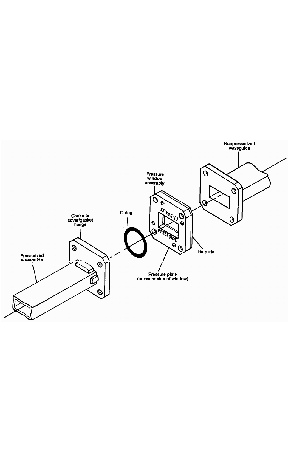
When mating two UG type flanges with the gasket grooves, two flange gasket
must be used, if flange with gasket groove is mated to flange without groove,
use one flange gasket. Two mating EIA type flanges use only one flange
gasket. Do not apply silicone grease to flange gaskets.
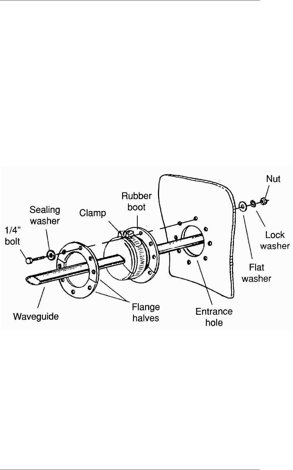
4.3 Wall/roof Feed-thru
These wall/roof feed-thru kits are designed to permit weatherproof path through
a roof or wall for elliptical waveguide. Each kit can be mounted to metal, wood
or concrete. A kit consists of a rubber boot, two metal flange halves, sealing
washers, and an adjustable clamp.
ELLIPTICAL
WAVEGUIDE
TYPE
NUMBER
KIT NUMBER
ENTRANCE
HOLE
DIAMETER
IN. (MM)
BOLT HOLE
CIRCLE IN. (MM)
NO. OF BOLT
HOLES
BOOT FLANGE
DIAMETER
IN. (MM)
EW 85
35849A-3
3 (80)
4 (102)
8
5 (127)
STEP 1 - Cut the entrance hole in the roof or wall to accommodate the cable
size. Refer to the chart for the proper dimension.
STEP 2 - Insert the waveguide or cable through the entrance hole and connect
it to the entrance hole and connect it to the components inside the building.
SRT X-BAND RADAR SYSTEMS
ANNEX
304202P003 19 Rev. C
STEP 3 - Apply silicone grease to the hole and slit of the rubber boot. Place the
boot on the waveguide or cable and over the entrance hole. Mark the locations
of the mounting holes.
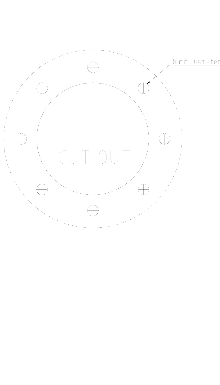
STEP 4 - Remove the boot and drill the mounting holes 5/16" (8 mm) through
the wall or roof. For concrete, either drill holes through the material or drill larger
holes deep enough to insert bolt anchors.
STEP 5 - Place the boot around the waveguide or cable and over the entrance
hole. Position the flange halves in the groove of the boot and align all of the
mounting holes. Fasten the assembly with 1/4" bolts, flat washers, and nuts
obtained locally. Place the sealing washer supplied under the bolt heads as
shown.
STEP 6 - Wrap the clamp around the boot as shown and tighten it with a
screwdriver to ensure a leak proof seal.
SRT X-BAND RADAR SYSTEMS
ANNEX
304202P003 20 Rev. C
FIG. 5.3.2 - WALL FEED THROUGH DRILLING TEMPLATE (Scale
1:1):
SRT X-BAND RADAR SYSTEMS
ANNEX
304202P003 21 Rev. C
4.4 Pressurisation
After all connections have been completed, pressurise waveguide. Changes in
temperature can cause moisture from outside air that enters waveguide to
condense and seriously impair efficiency, so waveguide must be under
pressure at all times.
If moist air has entered, must be purged. Remove gas port plug located on
connector at Antenna Group end of waveguide, and purge waveguide
continuously until it is dry. After purging, replace gas port plug and pressurise
waveguide.
Dry air is normally used for pressurising. Dry nitrogen may also be used. After
installation, check waveguide connections for leaks. Use commercial leak
detector or liquid detergent over joints and check for bubbles. Un-broken soap
film over entire joint for several minutes will indicate very small leaks.

SRT X-BAND RADAR SYSTEMS
FIGURES
304202P003 9.1 Rev. C
CHAPTER 9
FIGURES
The following figures and drawings are included after this pages:
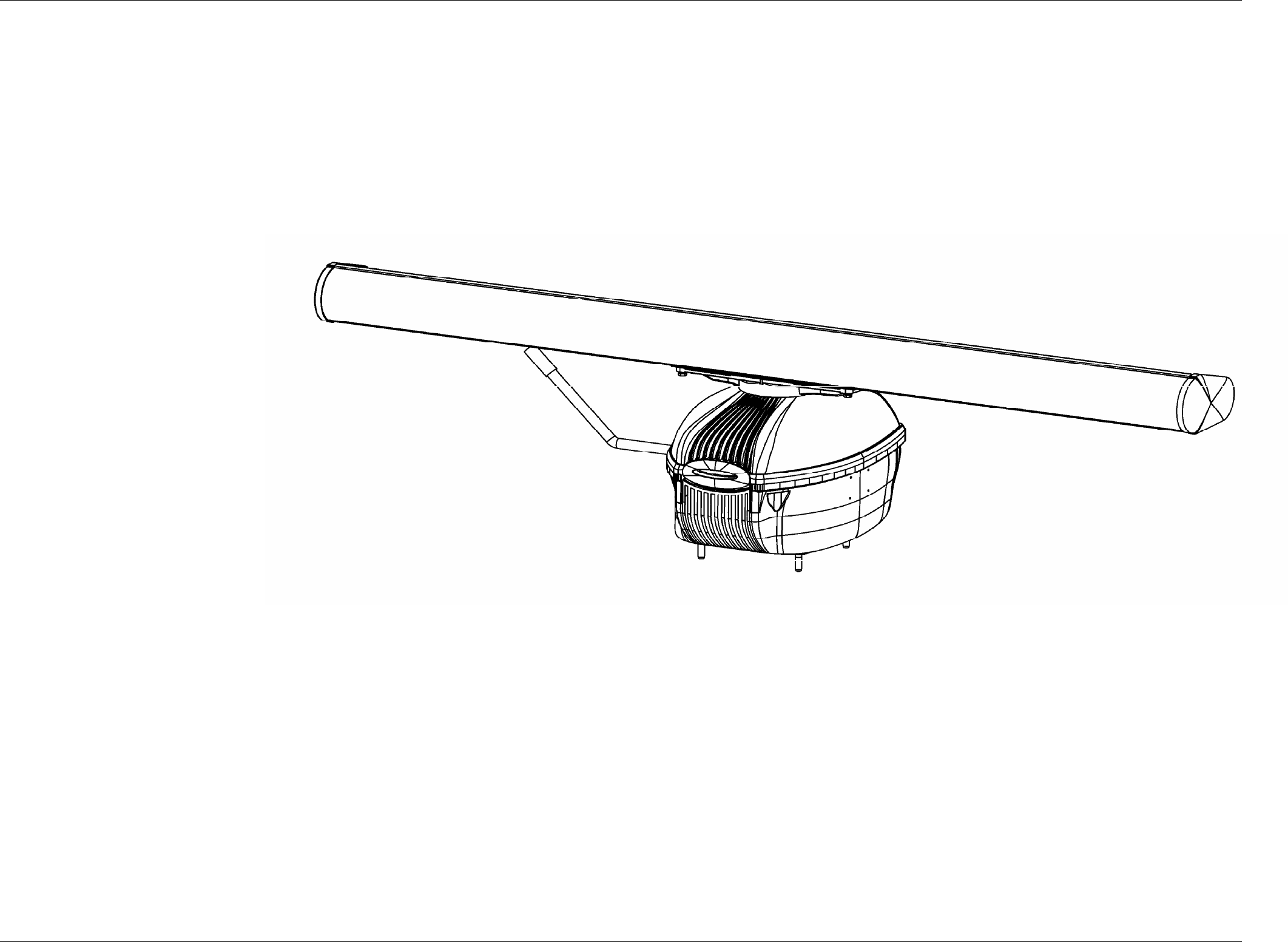
Figure 9.1.1 - SRT 12 KW - General View
Figure 9.1.2 - SRT 12 KW – External view
Figure 9.1.3 - Pedestal External View
Figure 9.1.4 - Pedestal Internal View
Figure 9.1.5 - Motoreducer assy
Figure 9.1.6 - Electronics Rack
Figure 9.1.7 - SRT Functional Block Diagram for 6’ Antenna
Figure 9.1.8 - SRT Internal Connection
Figure 9.1.9 - SRT Internal voltage and signals
Figure 9.1.10 - SRT_POWER - Board
Figure 9.1.11 - SRT_POWER – General block
Figure 9.1.12 - SRT_POWER – Protection circuits
Figure 9.1.13 - SRT_POWER – LVPS circuits
Figure 9.1.14 - SRT_POWER – HVPS circuits
Figure 9.1.15 - SRT_MOS – Board
Figure 9.1.16 - SRT_MOS – Block diagram
Figure 9.1.17 - SRT_CONTROL Board (Version A and B)
Figure 9.1.18 - SRT_CONTROL – Blocks
Figure 9.1.19 - SRT_CONTROL – Microprocessor and Gate Array
Figure 9.1.20 - SRT_CONTROL – Input interface

SRT X-BAND RADAR SYSTEMS
FIGURES
304202P003 9.2 Rev. C
Figure 9.1.21 - SRT_CONTROL – Output interface
Figure 9.1.22 - SRT_CONTROL – Monitor
Figure 9.1.3 - SRT RF HEAD – Functional block diagram
Figure 9.1.24 - SRT RF HEAD – L.N.F.E.
Figure 9.1.25 - SRT RF HEAD – RF Detector
Figure 9.1.26 - BRUSHLESS CONTROLLER – Functional blocks
Figure 9.1.27 - Electronics Rack – Particular of the RF Head
Figure 9.1.28 - RF Amplifier
Figure 9.1.29 - Electronics rack
Figure 9.1.30 - Bearing reader board
Figure 9.1.31 - Rotary joint
Figure 9.1.32 - Brushless Motor Controller
SRT X-BAND RADAR SYSTEMS
FIGURES
304202P003 9.3 Rev. C
Figure 9.1.1 SRT Up mast General View
SRT X-BAND RADAR SYSTEMS
FIGURES
304202P003 9.4 Rev. C
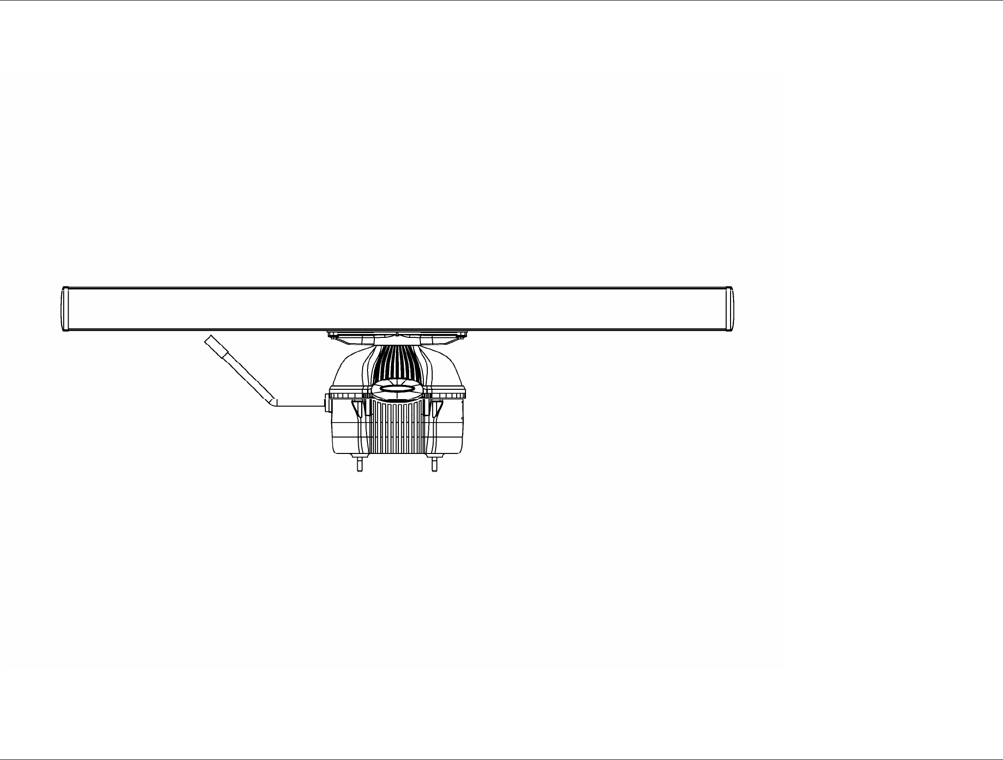
Figure 9.1.2 SRT Up mast– External view
SRT X-BAND RADAR SYSTEMS
FIGURES
304202P003 9.5 Rev. C
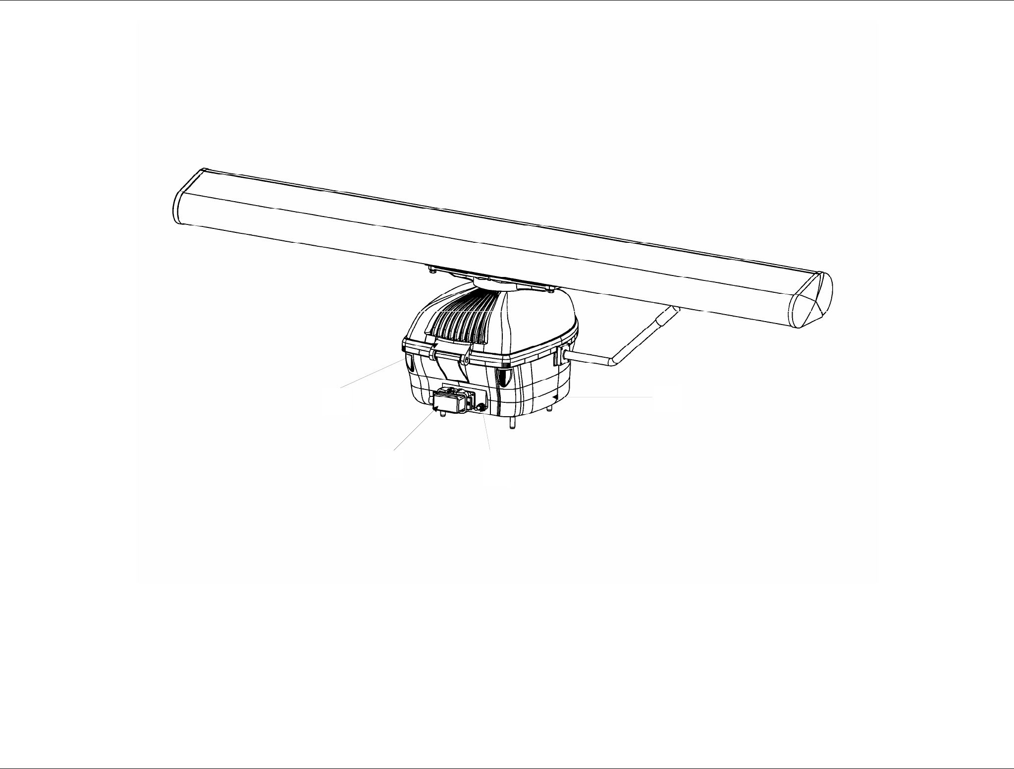
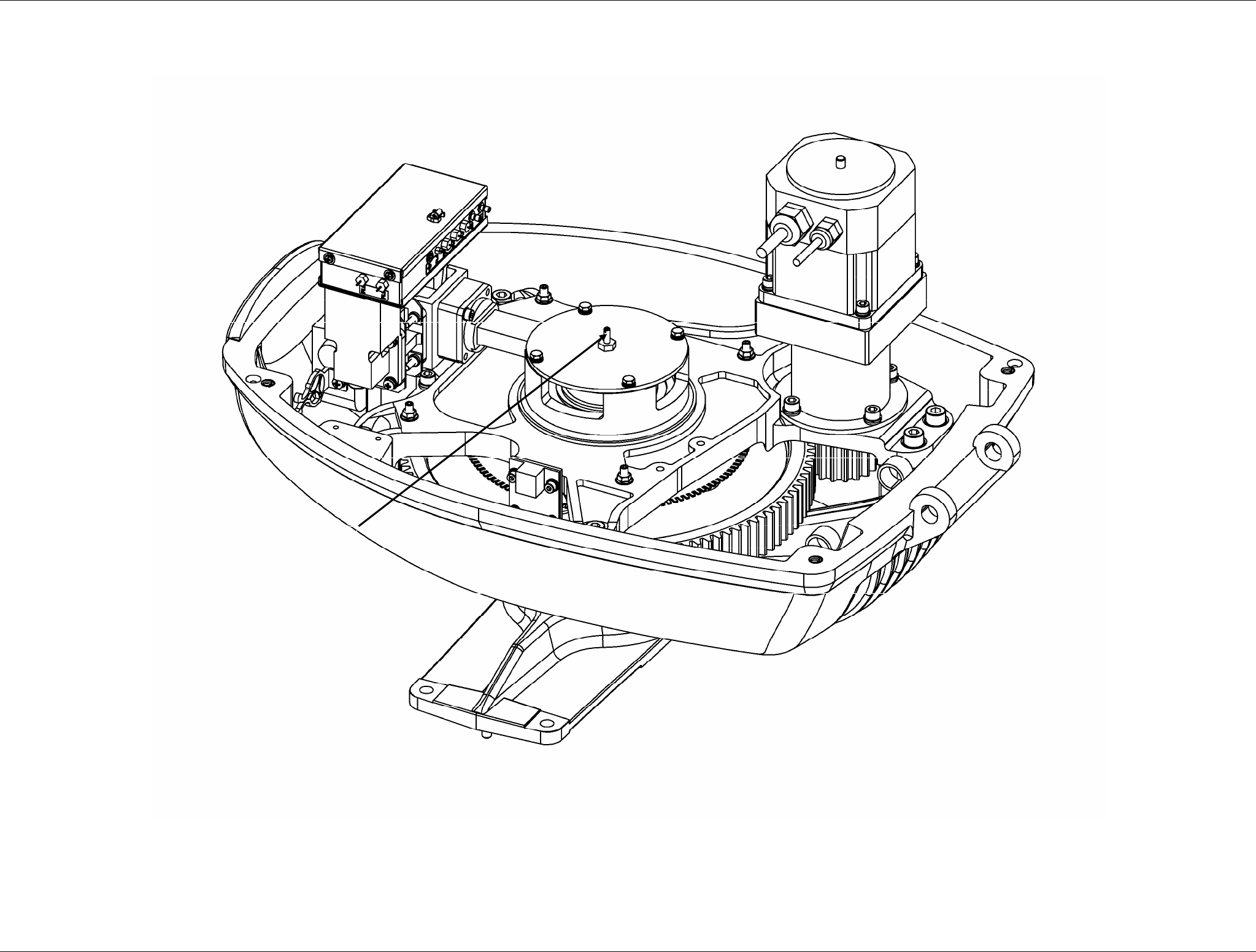
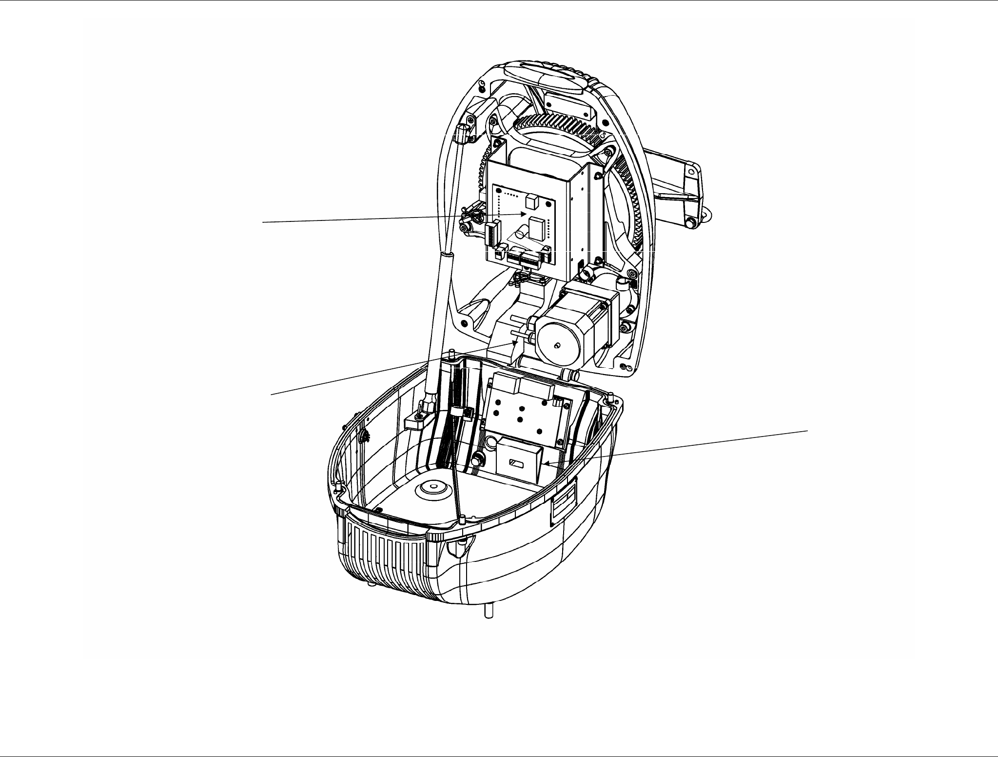
Figure 9.1.3 Pedestal External View
1
4
3
2
SRT X-BAND RADAR SYSTEMS
FIGURES
304202P003 9.6 Rev. C
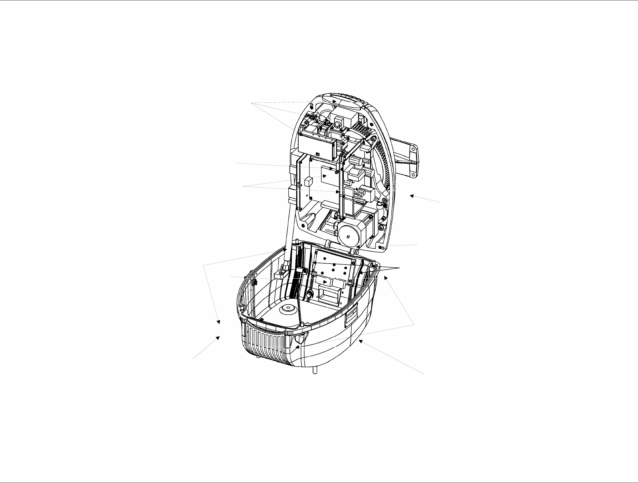
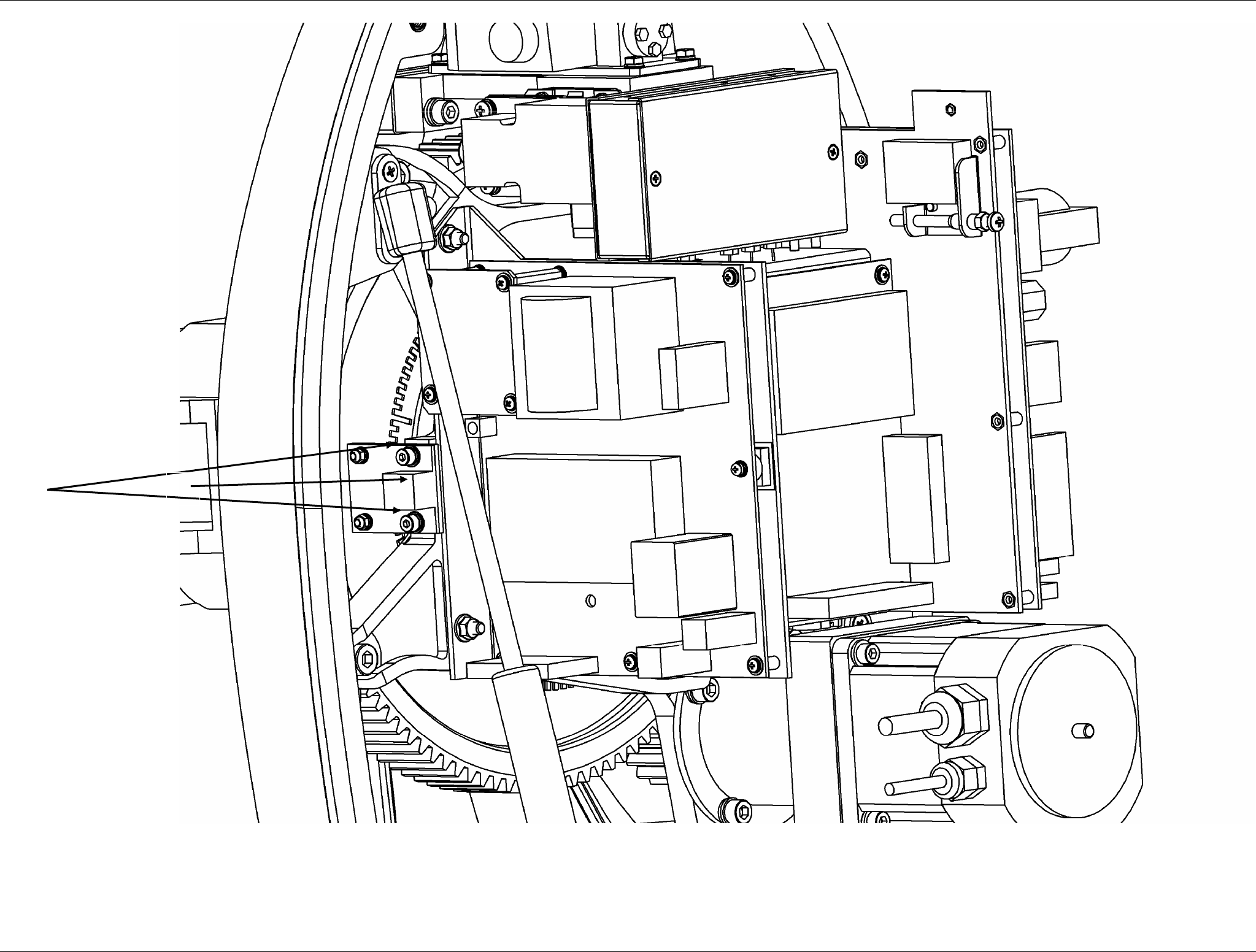
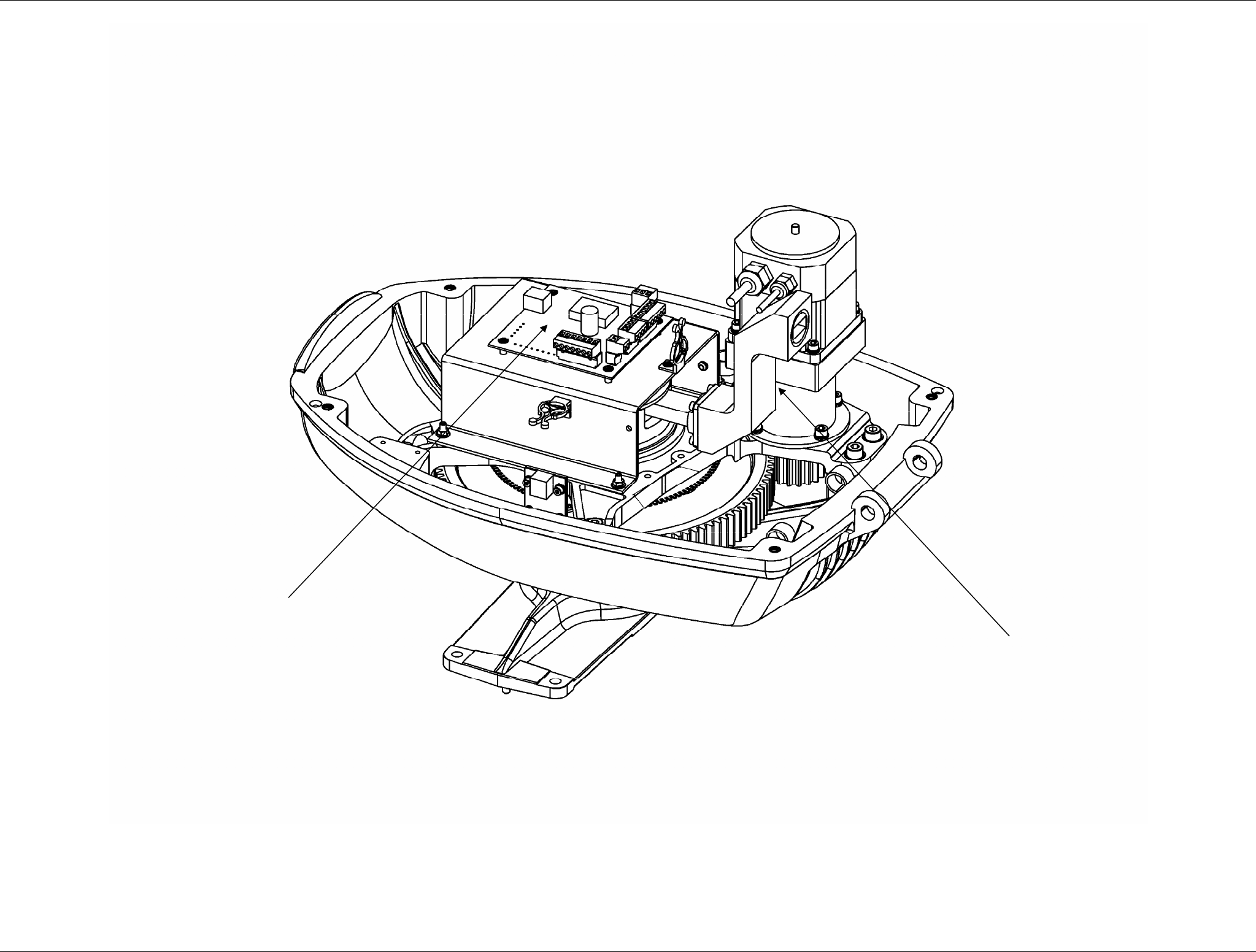
Figure 9.1.4 Pedestal Internal View
3
1
1
2
5
4
9
6
7
8
10
SRT X-BAND RADAR SYSTEMS
FIGURES
304202P003 9.7 Rev. C
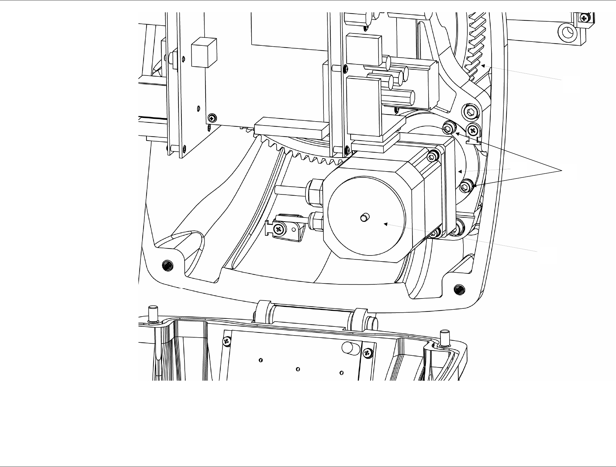
Figure 9.1.5 Motoreducer assy
1
2
3
4
SRT X-BAND RADAR SYSTEMS
FIGURES
304202P003 9.8 Rev. C
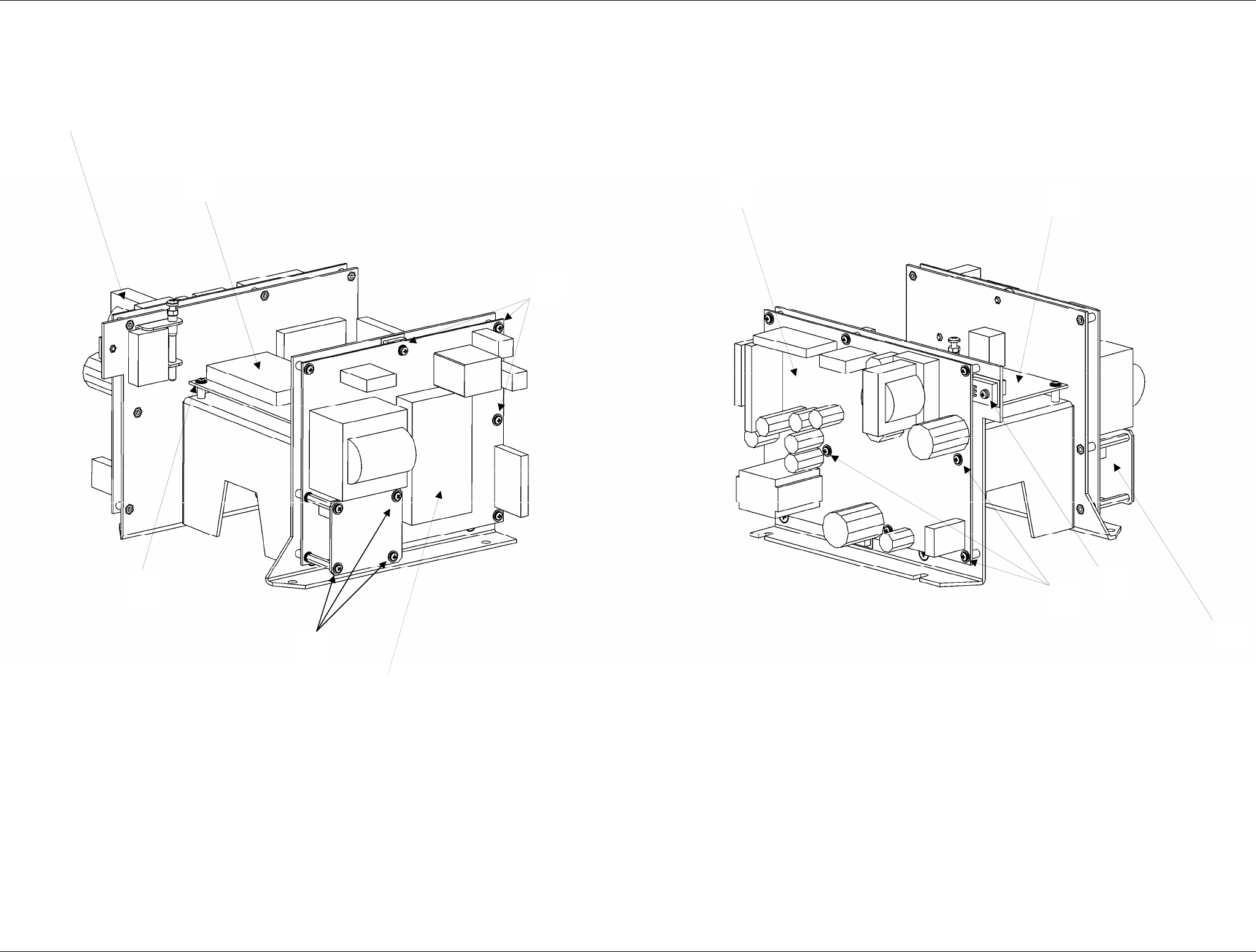
Figure 9.1.6 Electronics Rack
2
3
1
4
6 8
8
7
7
6
9
SRT X-BAND RADAR SYSTEMS
FIGURES
304202P003 9.9 Rev. C
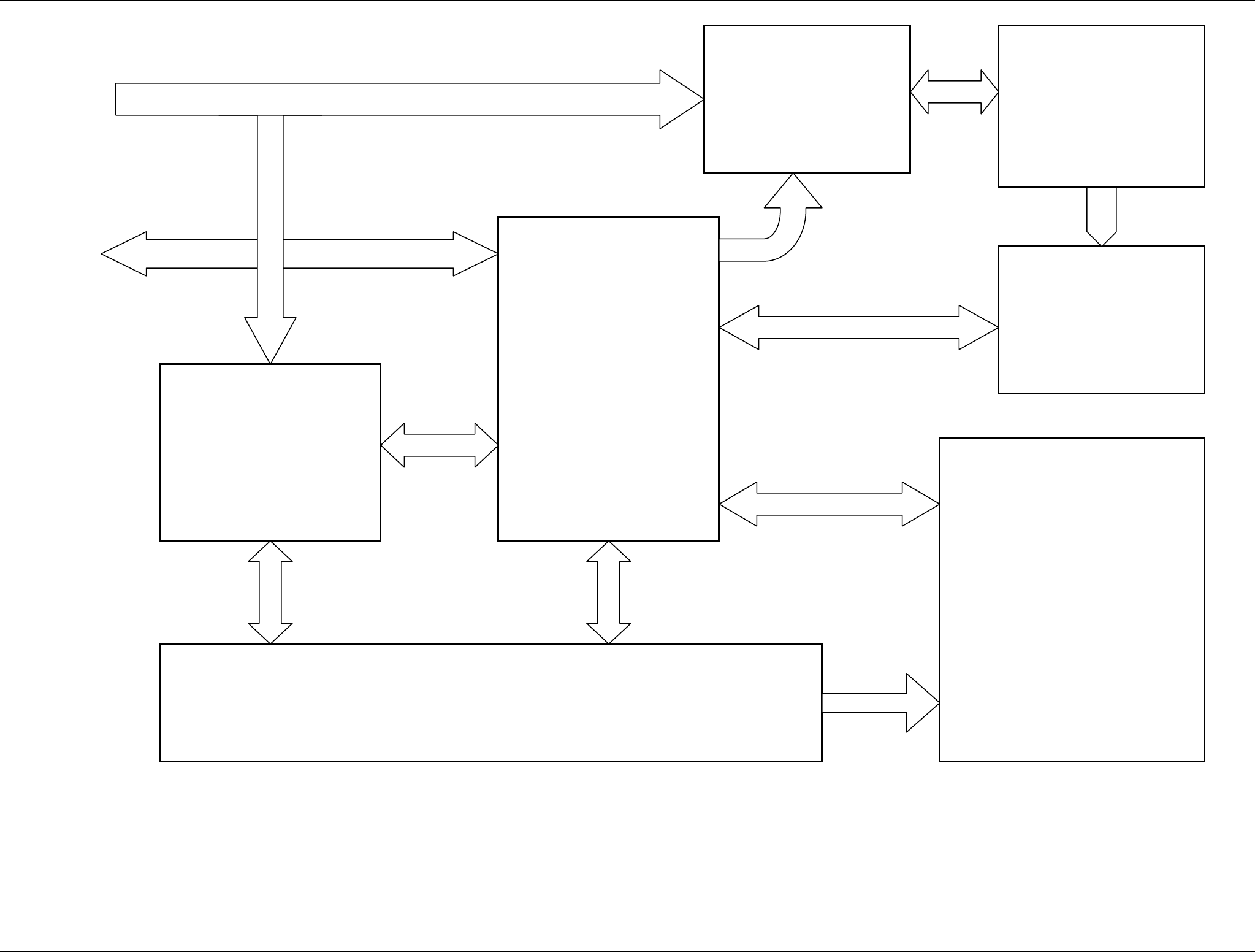
Figure 9.1.7 SRT Functional Block Diagram for 6’ Antenna
SRT_Power
SRT_Control
Speed
Control
RF Head
Brushless
Motor
SRT_Mos
Bearing Reader
Controls
Main Power
SRT X-BAND RADAR SYSTEMS
FIGURES
304202P003 9.10 Rev. C
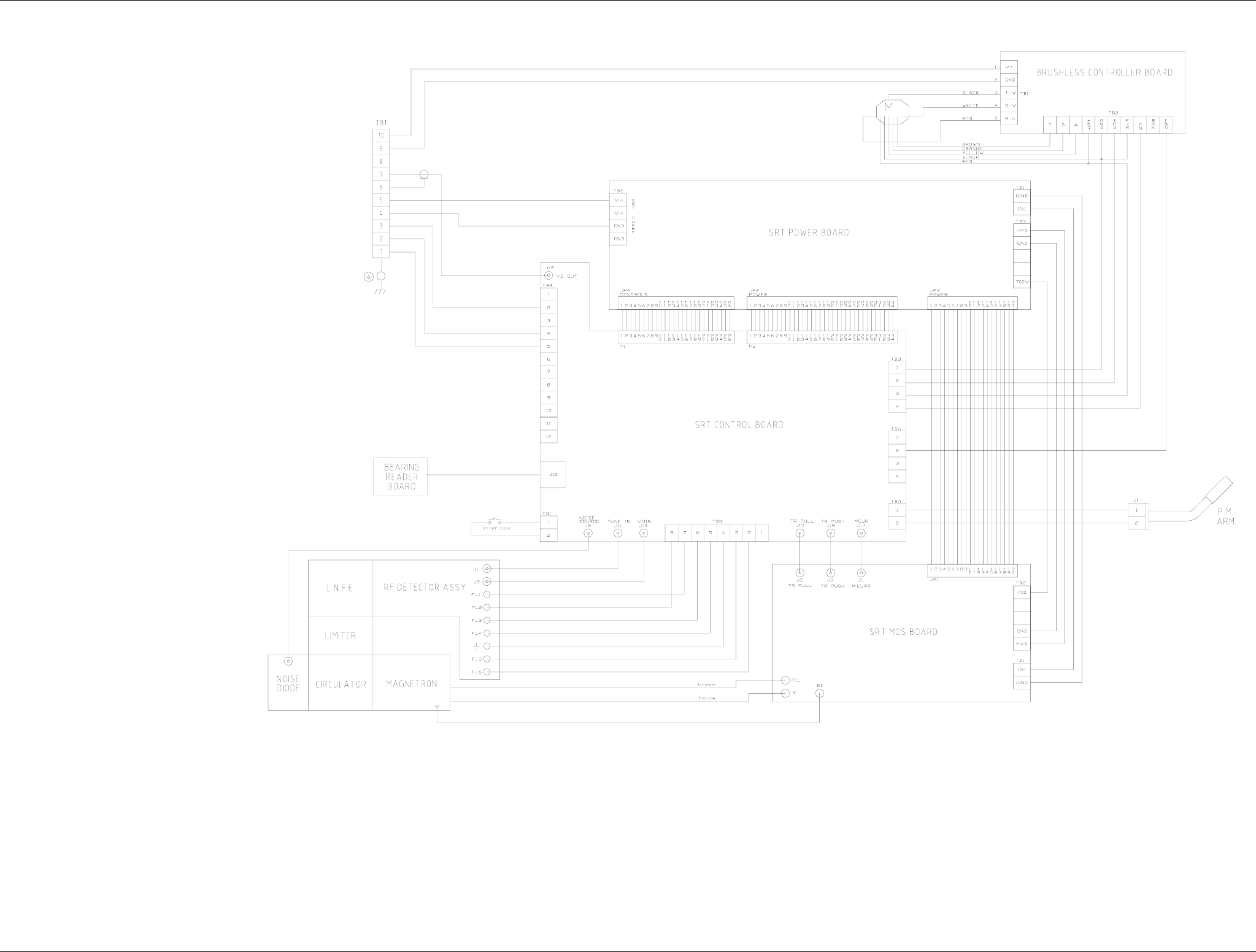
Figure 9.1.8 SRT Internal Connection
SRT X-BAND RADAR SYSTEMS
FIGURES
304202P003 9.11 Rev. C
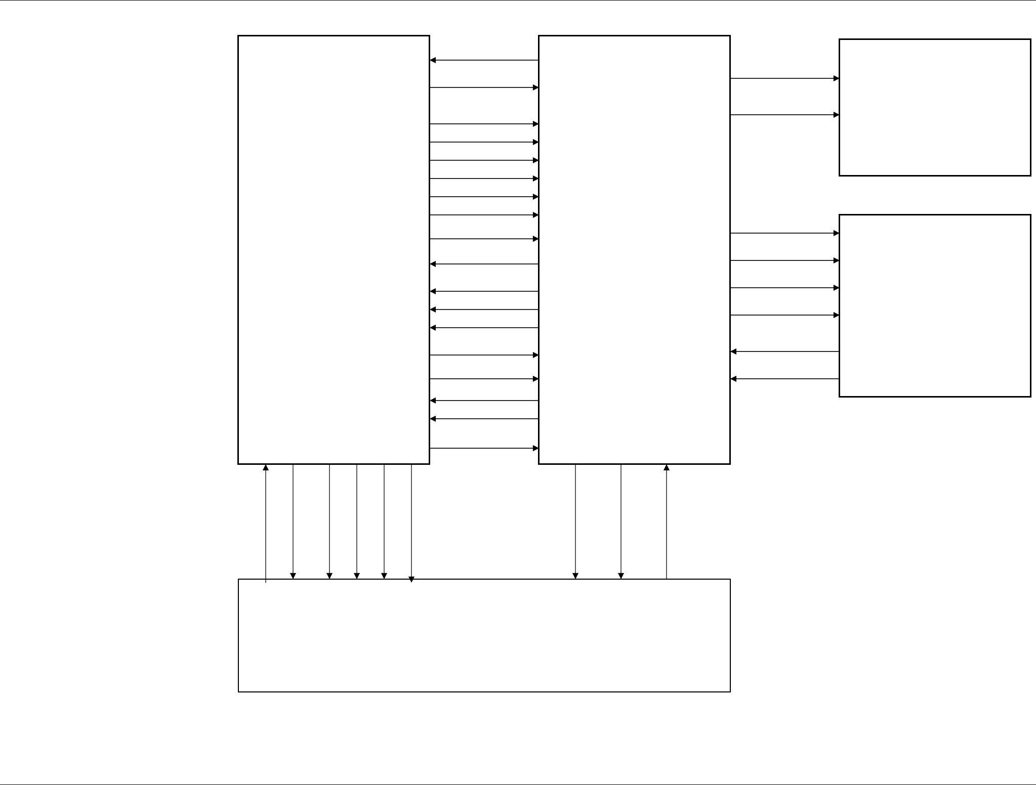
Figure 9.1.9 SRT Internal voltage and signals
SRT_Power
SRT_Control
PWON
+
5V
+15V
-15V
-5V
+150V
+24V
HV OK
HVON
SPA
MPA
LPA
LINE
HV STOP
SW Fil
Fil ON
V Fil
SRT_Mos
12 VT
Speed
Control
Start
Vel
RF Amplifier
STC
SB1
SB2
+
5V
Video
Tune
M.PC
TR Pull
TR Push
15 Iso
- 5 V
+ 15 V
+ 700 V
V Fil
HV Stop
SRT X-BAND RADAR SYSTEMS
FIGURES
304202P003 9.12 Rev. C
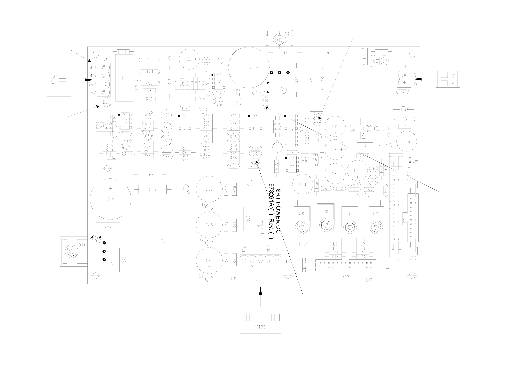
Figure 9.1.10 SRT_POWER - Board
3
1
2
4
5
SRT X-BAND RADAR SYSTEMS
FIGURES
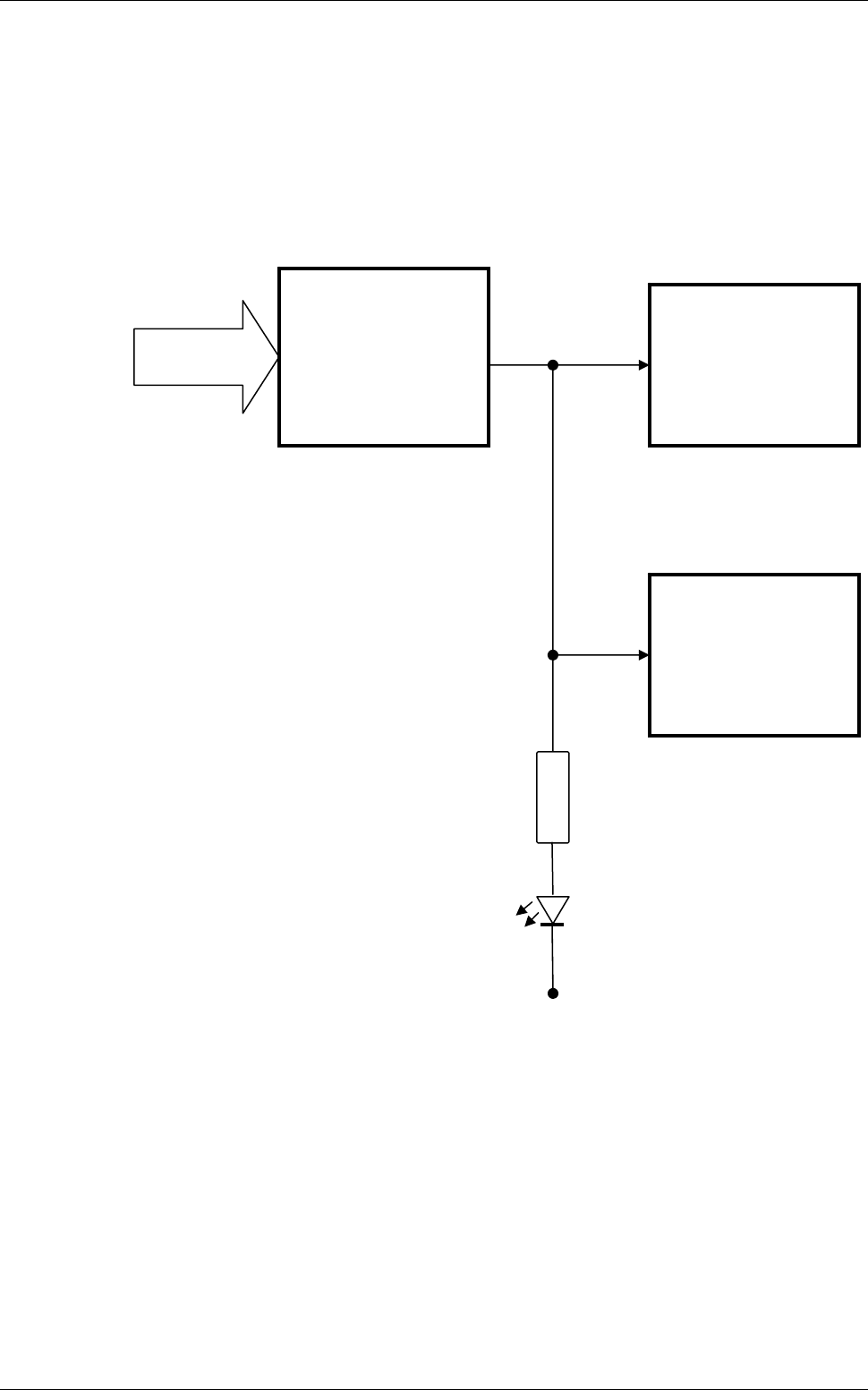
304202P003 9.13 Rev. C
50 Vdc
Input
Protection
L.V.P.S.
H.V.P.S.
DL1
GND
R8
SRT X-BAND RADAR SYSTEMS
FIGURES
304202P003 9.14 Rev. C
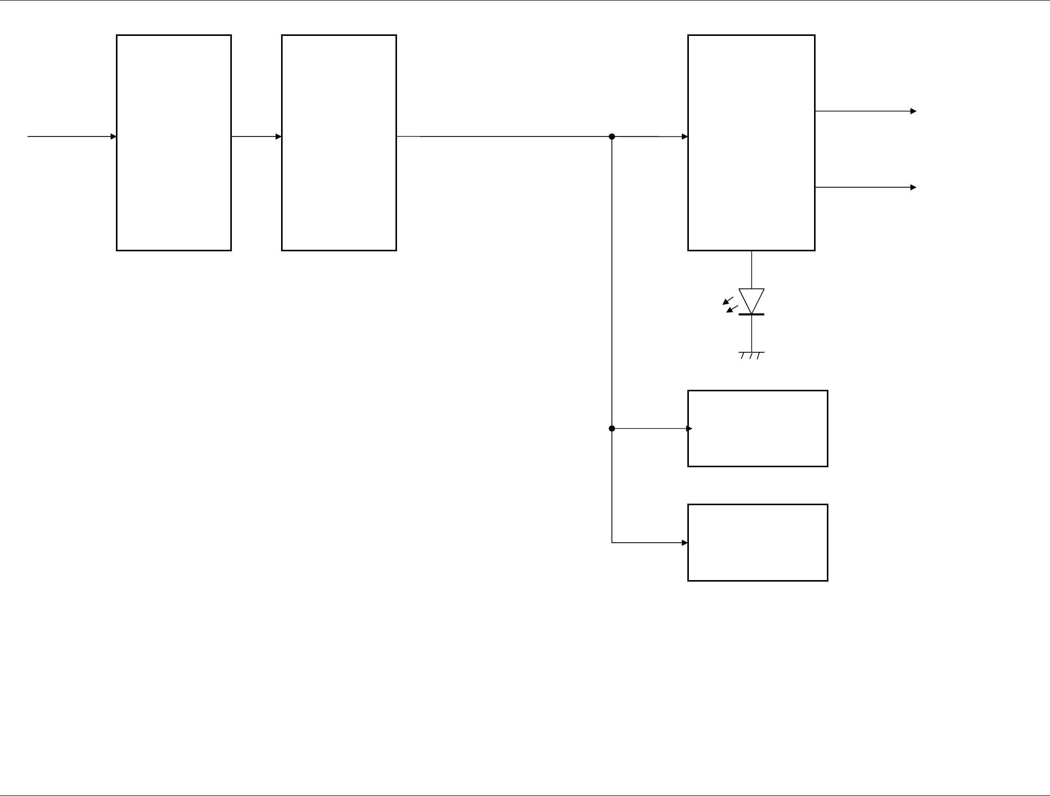
Figure 9.1.12 SRT_POWER – Protection circuits
50 Vdc
Over Current
protection
Wrong polarity
protection
Voltage
sensor
DL1
To SRT_Control
12 VT
Line
To SRT_Control
LVPS
HVPS
SRT X-BAND RADAR SYSTEMS
FIGURES
304202P003 9.15 Rev. C
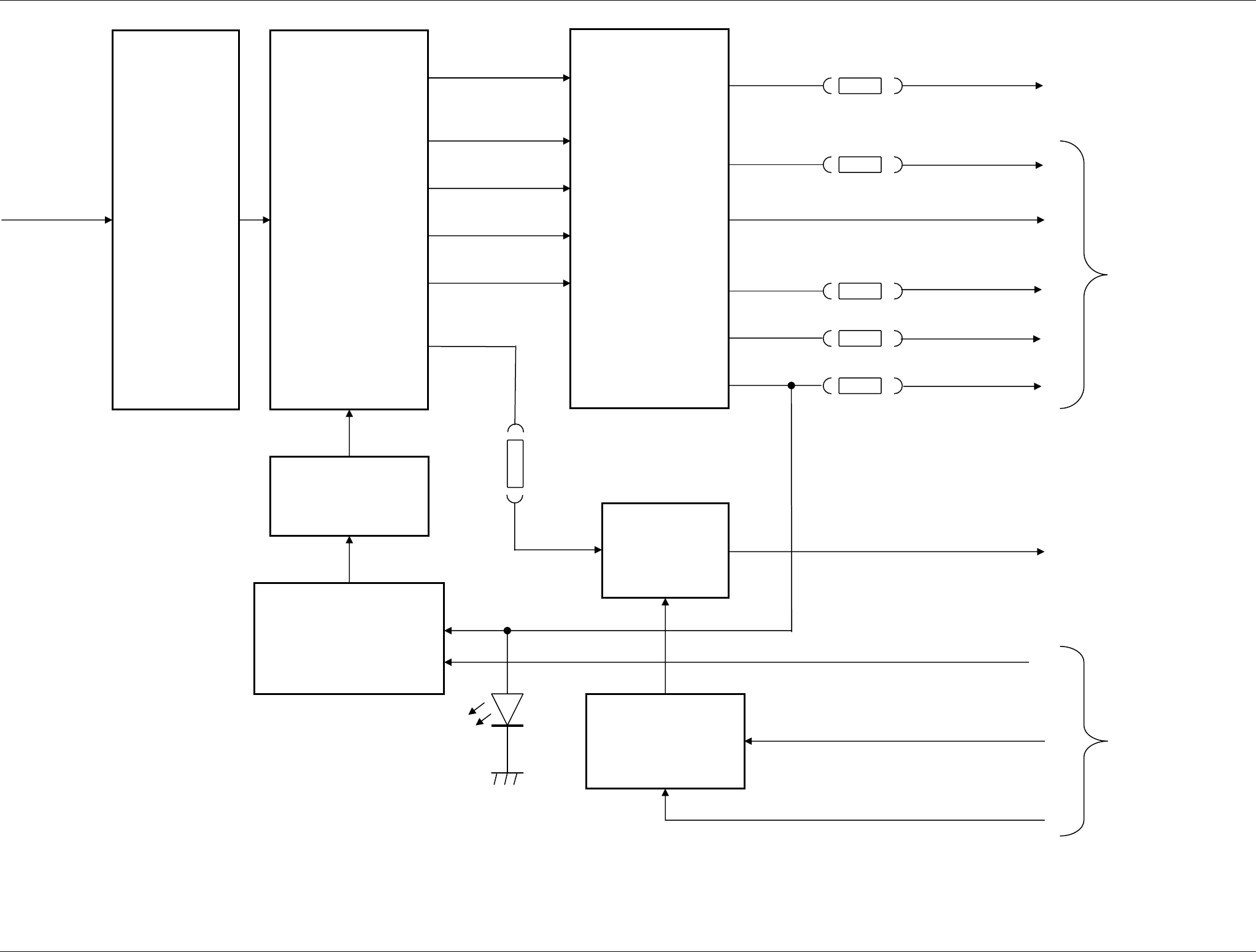
Figure 9.1.13 SRT_POWER – LVPS circuits
50 Vdc
Filters
&
Regulators
+15 Iso
+5V
+15VF
+24V
-5V
-15VF
5 Vac
16 Vac
Transformer
MOSFET
V FIL
VFIL CONTROLLER
General
power supply
F3
SW Fil
From SRT_Control
FLYBACK
CONTROLLER
MOSFET
To
SRT_MOS and
SRT_Control
24 Vac
16 Vac
16 IVac
Fil ON
F4
F6
F7
F5
PW ON
Filter
F2
To
SRT_MOS
DL2
SRT X-BAND RADAR SYSTEMS
FIGURES
304202P003 9.16 Rev. C
Figure 9.1.14 SRT_POWER – HVPS circuits
50 Vdc
Filters
&
Regulators
+ 150 V
+ 700 V
700 Vac
Transformer
MPA
From / To
SRT_Control
FLYBACK
CONTROLLER
MOSFET
230 Vac
460 Vac
SPA
HV ON
Filter
To SRT_MOS
LPA
Feedback
and
Controls
HV OK
DL3 HV Stop
To SRT_Control
From SRT_MOS
SRT X-BAND RADAR SYSTEMS
FIGURES
304202P003 9.17 Rev. C
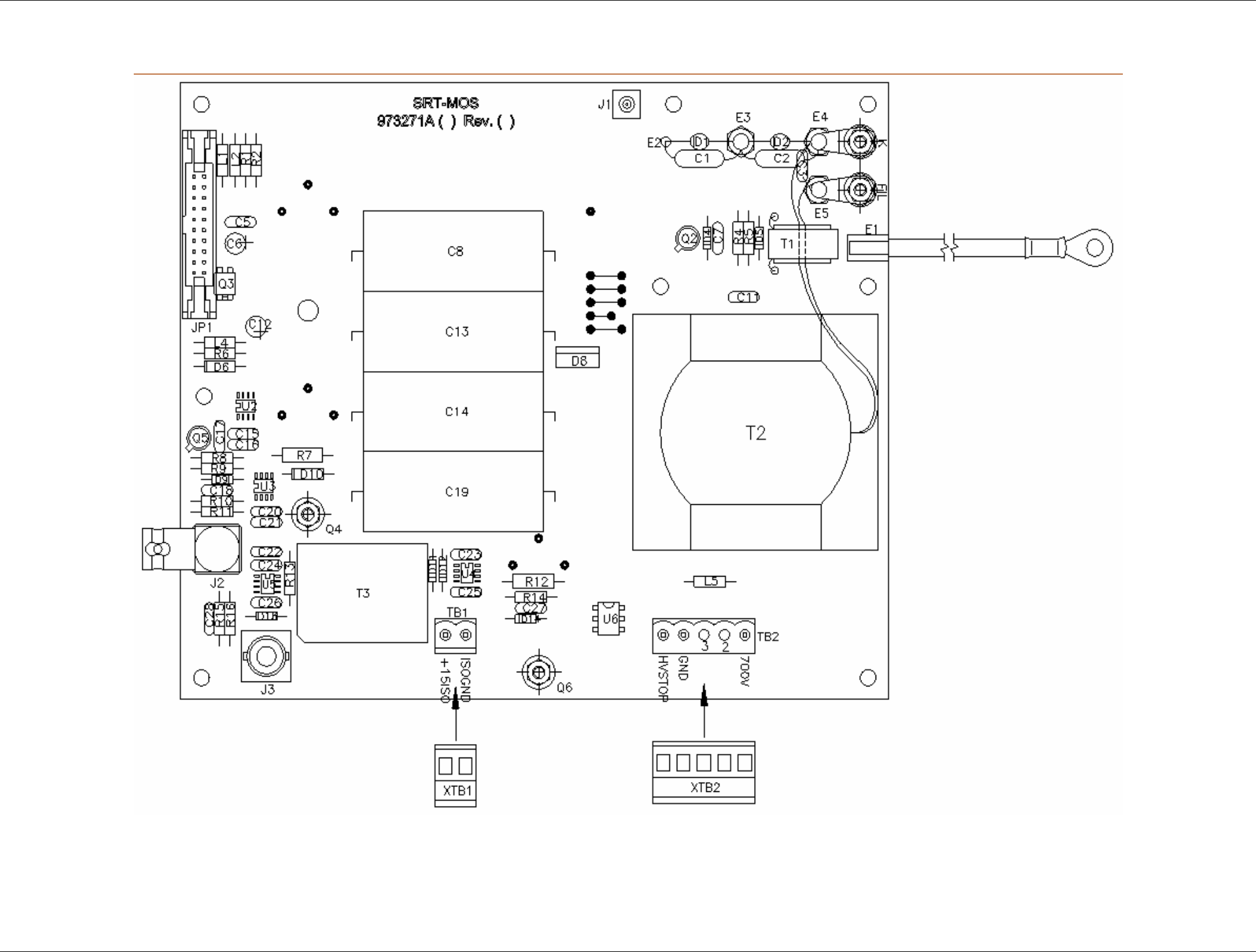
Figure 9.1.15 SRT_MOS – Board
SRT X-BAND RADAR SYSTEMS
FIGURES
304202P003 9.18 Rev. C
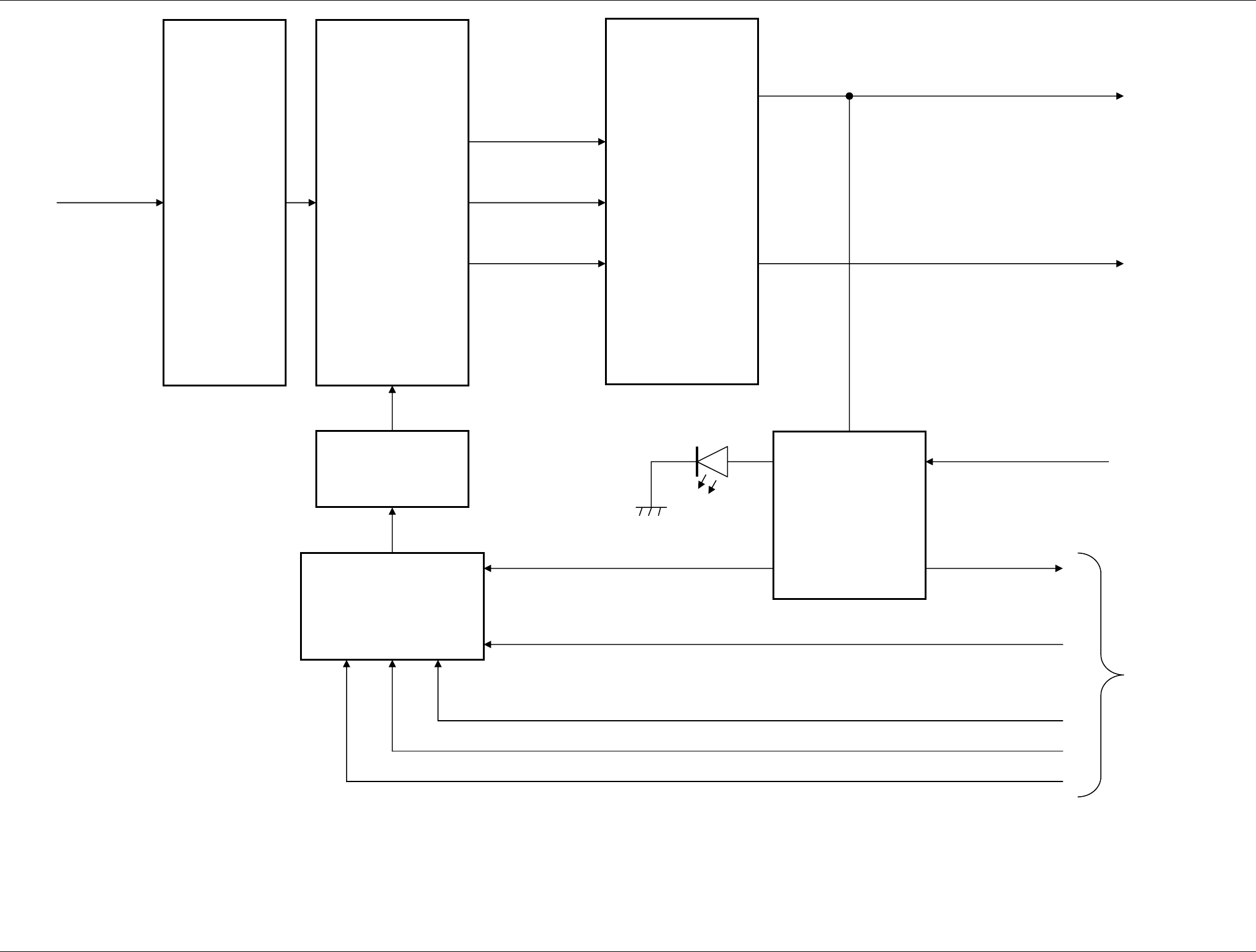
Figure 9.1.16 SRT_MOS – Block diagram
TR Push
From
SRT_Control
Isolation
Transformer
Mosfet
Driver
Driver
TR Pull
Mosfet
From
SRT_Power
+ 15 V
+ 15 Iso
+ 15 V
- 5 V
From / to
SRT_Power
+ 700 V
Current
Transformer
Fil ( Green )
K ( Yellow )
Magnetron Gnd
To
Magnetron
Magnetron Current To SRT_Control
Pulse Transformer
V Fil
15 Iso
Sensor
HV Stop
Driver
SRT X-BAND RADAR SYSTEMS
FIGURES
304202P003 9.19 Rev. C
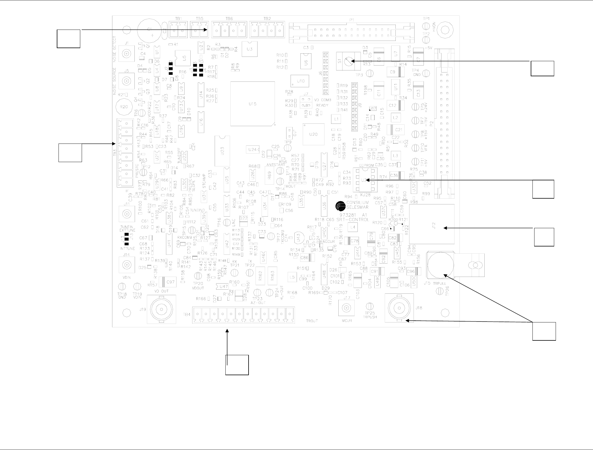
Figure 9.1.17 SRT_CONTROL Board
1
2
7
6
3
4
5
SRT X-BAND RADAR SYSTEMS
FIGURES
304202P003 9.20 Rev. C
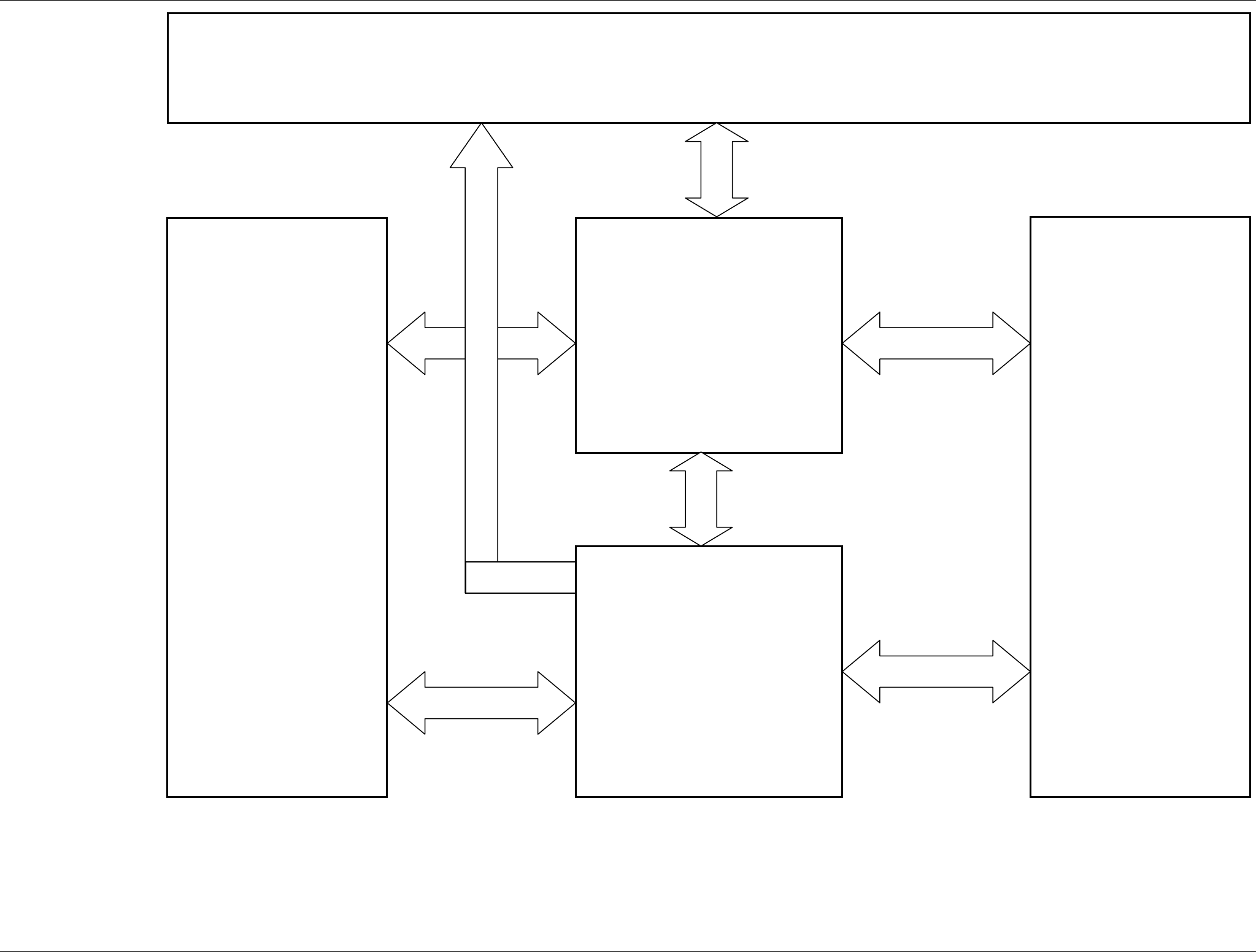
Figure 9.1.18 SRT_CONTROL – Blocks
Microprocessor
Gate Array
Output Interface
Monitor ( Performance and Voltage )
Input Interface
SRT X-BAND RADAR SYSTEMS
FIGURES
304202P003 9.21 Rev. C
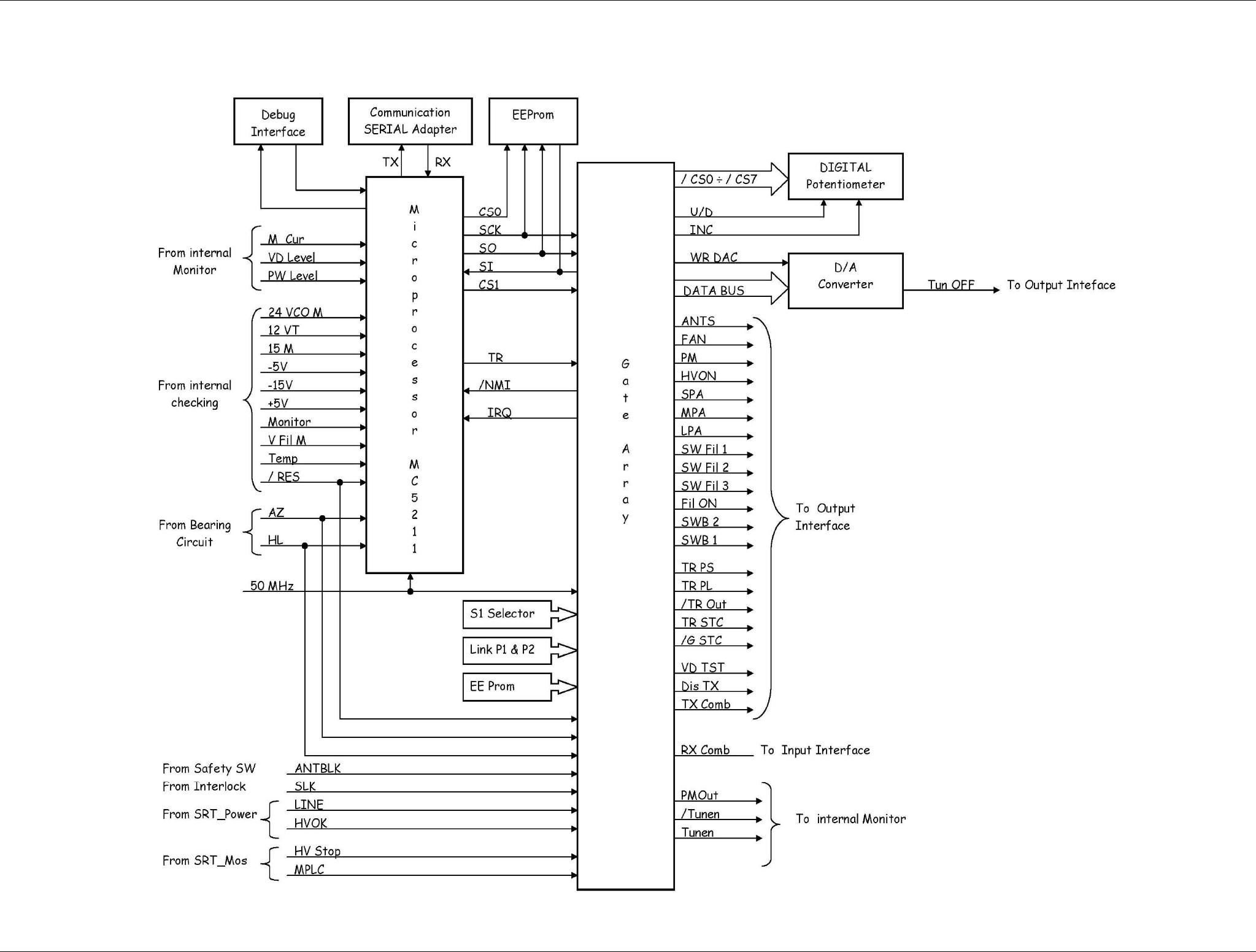
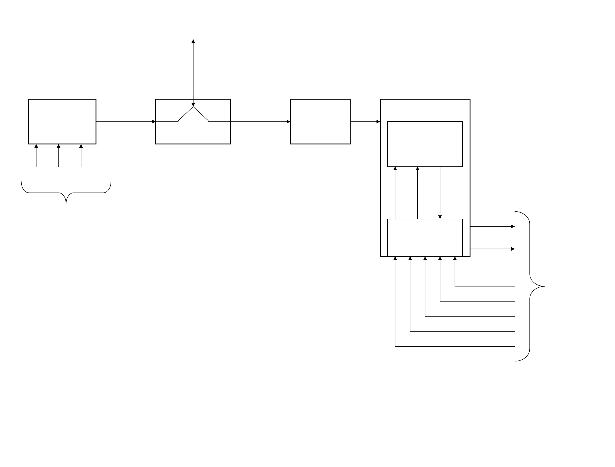
Figure 9.1.19 SRT_CONTROL – Microprocessor and
Gate Array
SRT X-BAND RADAR SYSTEMS
FIGURES
304202P003 9.22 Rev. C
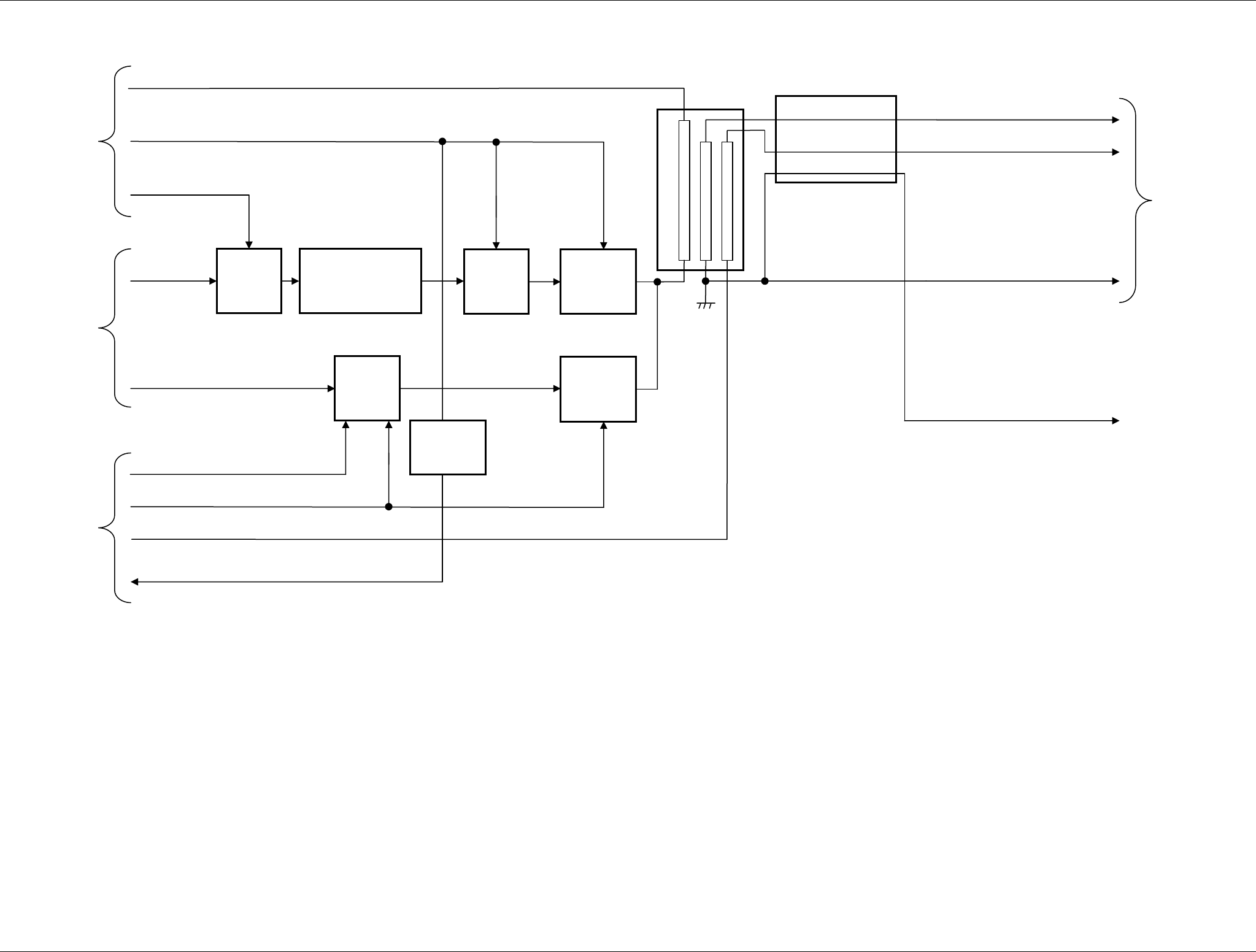
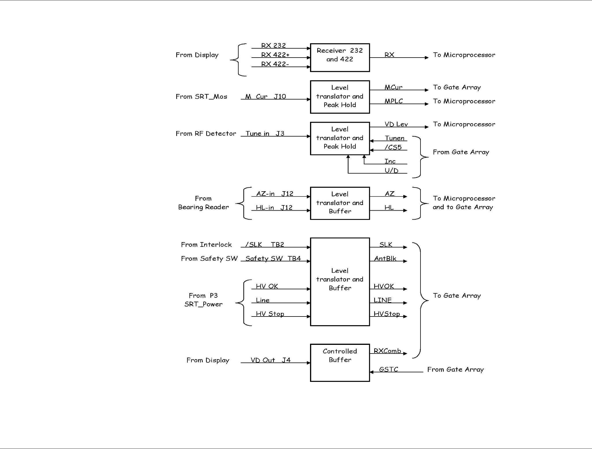
Figure 9.1.20 SRT_CONTROL – Input interface
SRT X-BAND RADAR SYSTEMS
FIGURES
304202P003 9.23 Rev. C
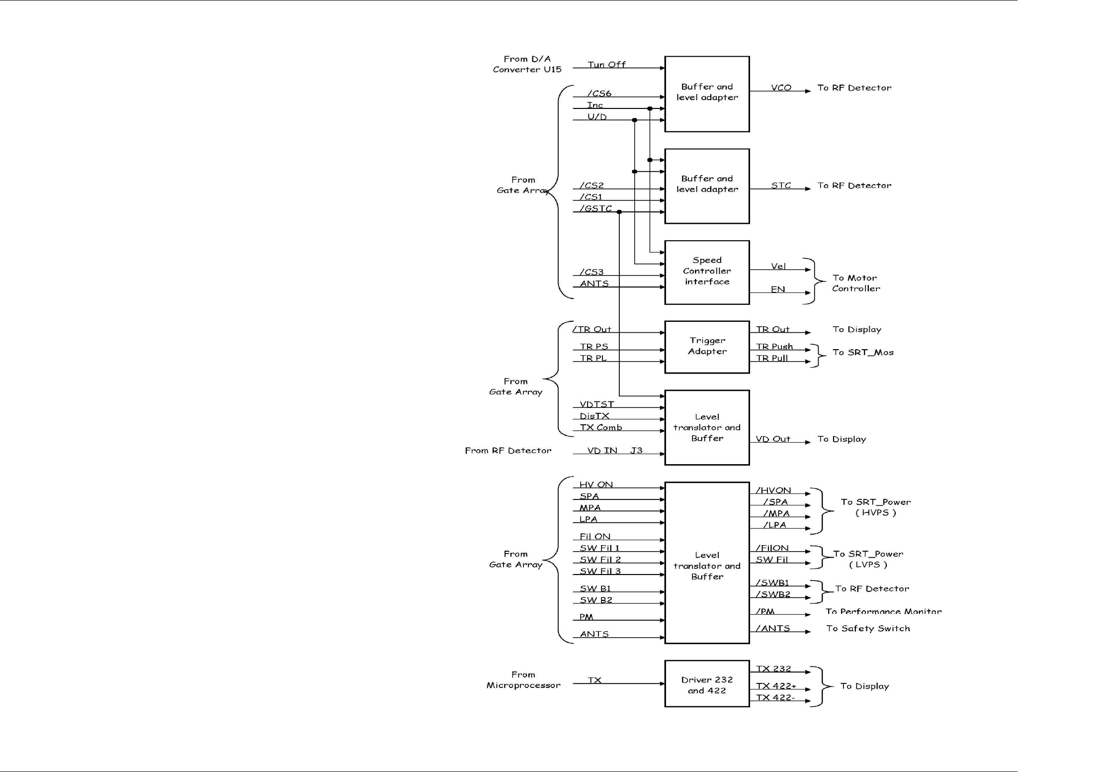
Figure 9.1.21 SRT_CONTROL – Output interface
SRT X-BAND RADAR SYSTEMS
FIGURES
304202P003 9.24 Rev. C
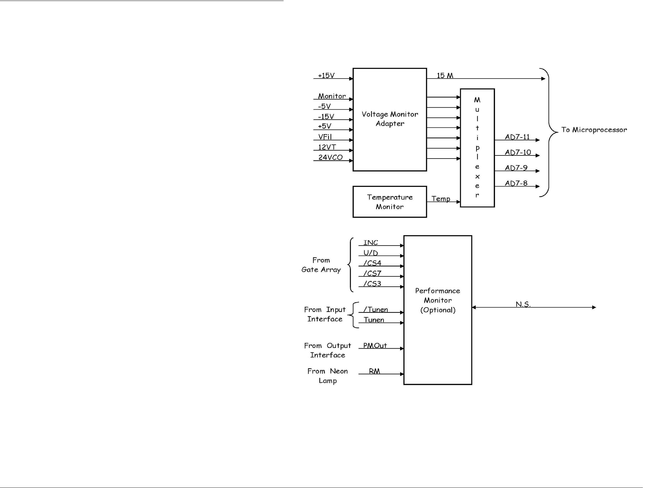
Figure 9.1.22 SRT_CONTROL – Monitor
SRT X-BAND RADAR SYSTEMS
FIGURES
304202P003 9.25 Rev. C
Figure 9.1.23 SRT RF HEAD – Functional block diagram
Magnetron
Circulator
Limiter
RF
Pulse
ECHO
Pulse
TO - FROM
ANTENNA
RF and
ECHO Pulse
A K FIL
From SRT_MOS
RF Amplifier
Low Noise Front
End
RF Detector
+5V
Tune
60MHz
+5V
SB1
SB2
STC
V Tune
Tune
Video
From / To
SRT_Control
SRT X-BAND RADAR SYSTEMS
FIGURES
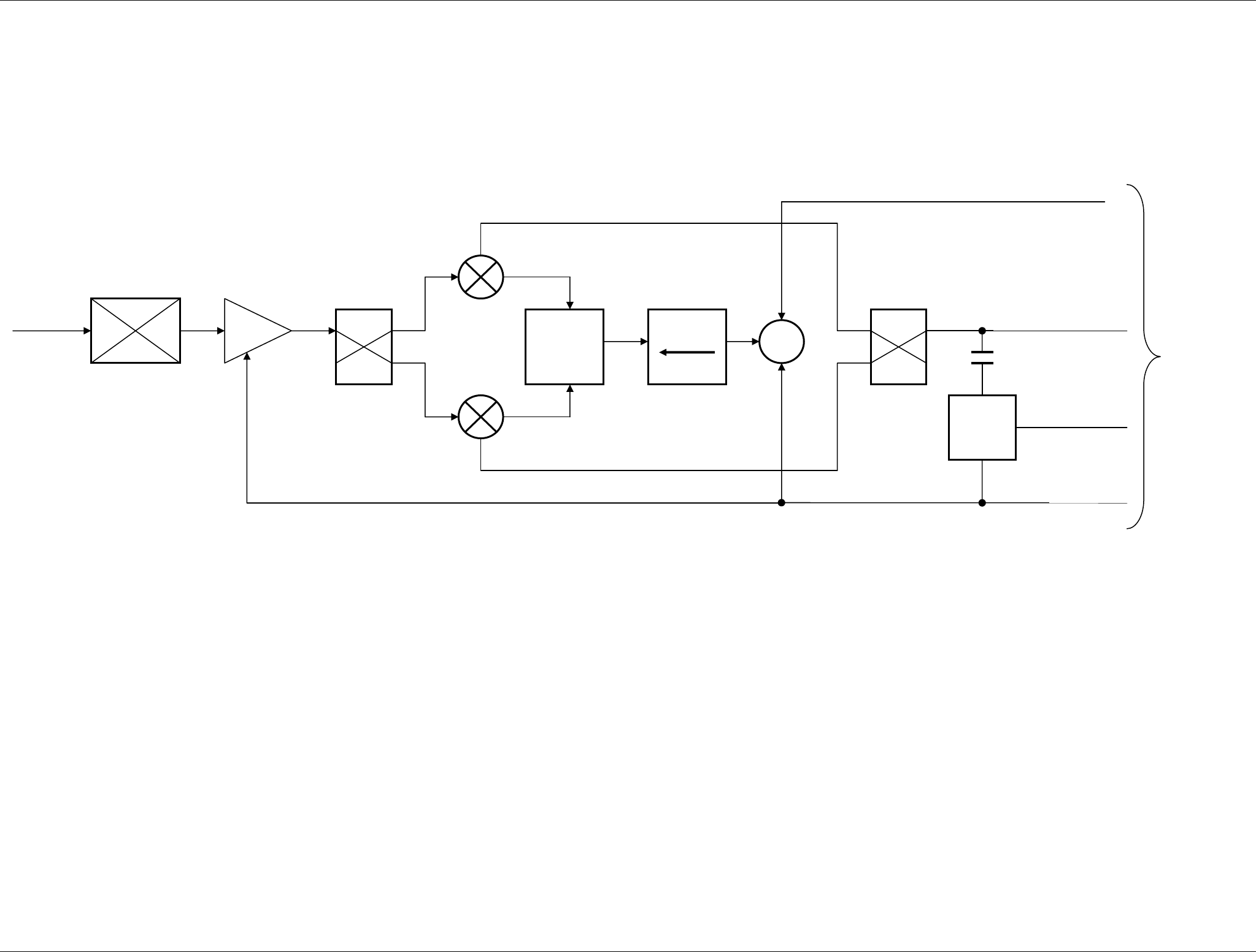
304202P003 9.26 Rev. C
Figure 9.1.24 SRT RF HEAD – L.N.F.E.
WG-Mic
Transition
RF in 0°
90° Balanced
Mixer
LNA
Balanced
Mixer
Divider
0°
0°
Isolator
~
0°
90°
60 MHz IF Out
+
5 Vdc
Tune Voltage
Moni
CKT
Monitor Out
From / To
RF Detector
SRT X-BAND RADAR SYSTEMS
FIGURES
304202P003 9.27 Rev. C
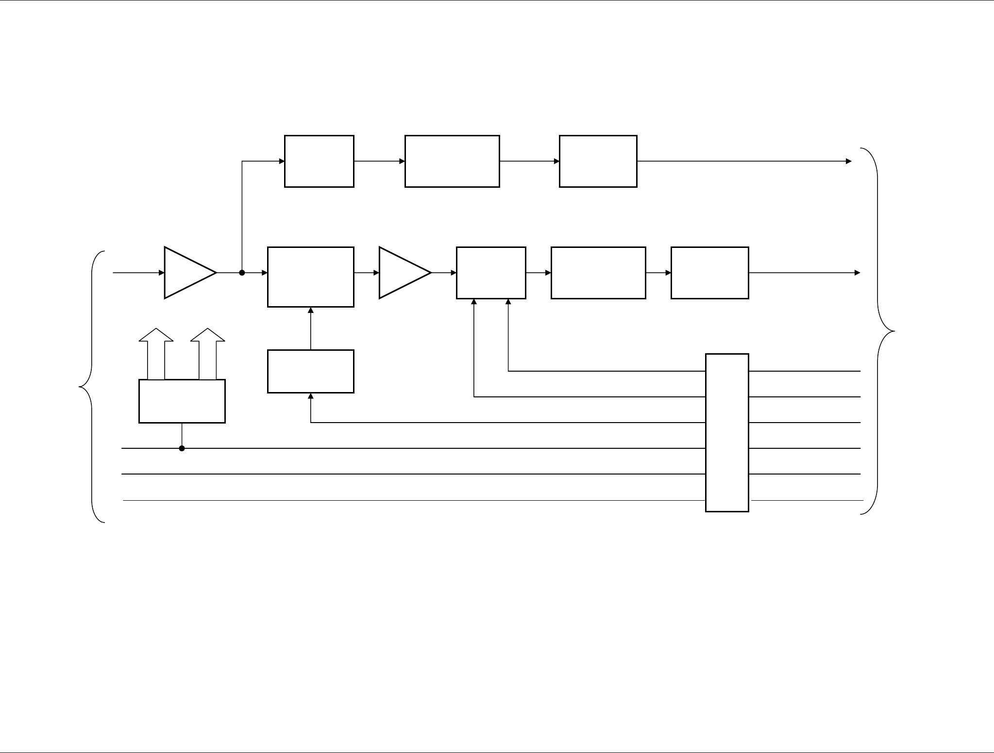
Figure 9.1.25 SRT RF HEAD – RF Detector
BP Filter
RF in
20 dB
50 dB
Variable
Attenuator
Logaritinc
Amplifier
S
W
B1
+
5 V
d
c
Tune Voltage
Buffer
From / To
SRT_Control
From / To
RF Detector
32 dB
Band
selector
Logaritinc
Amplifier
Buffer
Video Out
Tune Out
STC
Level
translator
DC/DC
Converter
Filters
+ 12V
- 12V
Monitor
SRT X-BAND RADAR SYSTEMS
FIGURES
304202P003 9.28 Rev. C
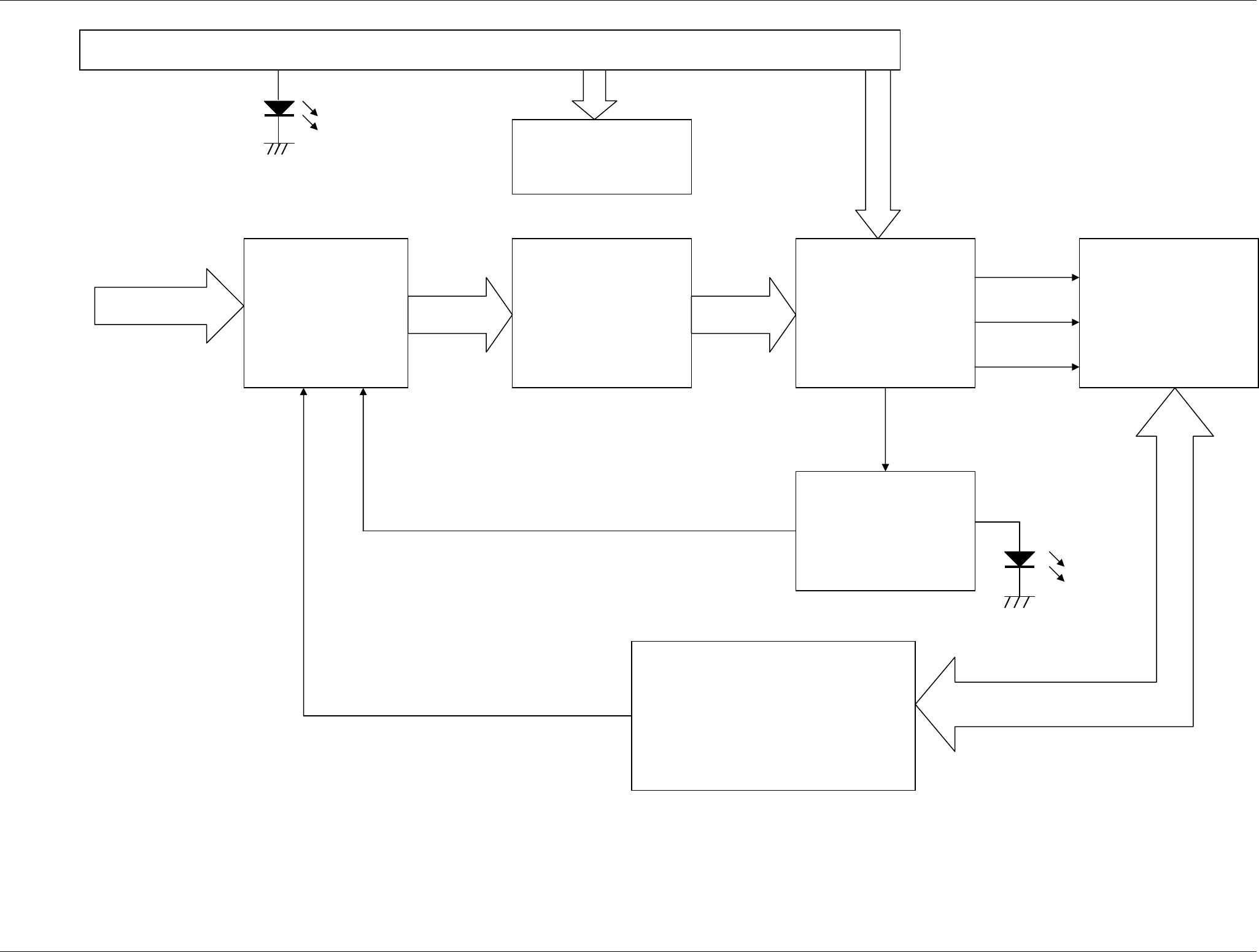
Figure 9.1.26 BRUSHLESS CONTROLLER – Functional
blocks
MC 33035
Brushless Controller
3 X IR 2103
Half Bridge Driver
6 Power Mosfet
R
S
T
Brushless
Motor
Closed Loop
Brushless Motor Adapter
MC 33039
Current Sensor
LM 7812
Main Power
Controls
Red Led
Green Led
SRT X-BAND RADAR SYSTEMS
FIGURES
304202P003 9.29 Rev. C
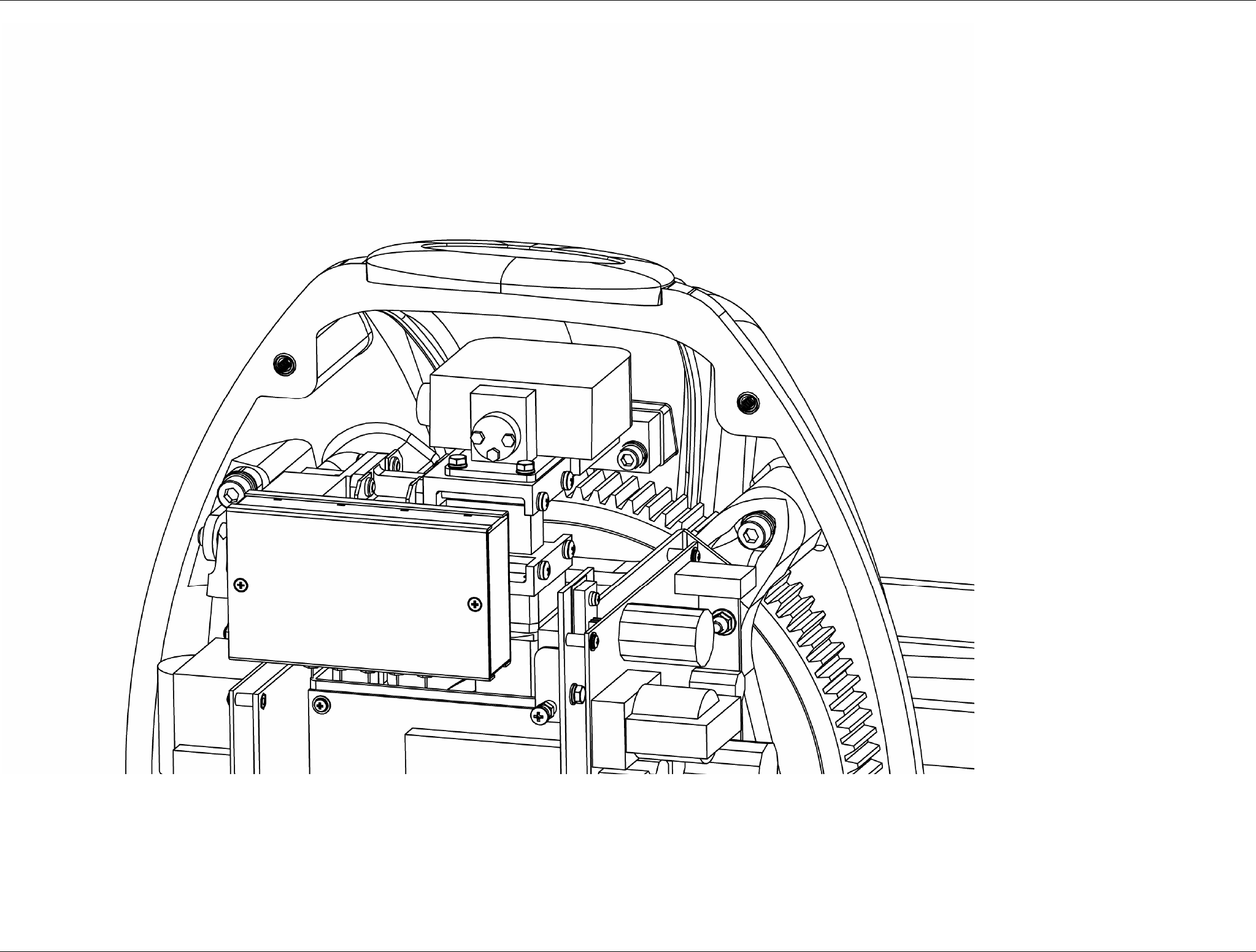
Figure 9.1.27 Electronics Rack – Particular of the RF
Head
SRT X-BAND RADAR SYSTEMS
FIGURES
304202P003 9.30 Rev. C
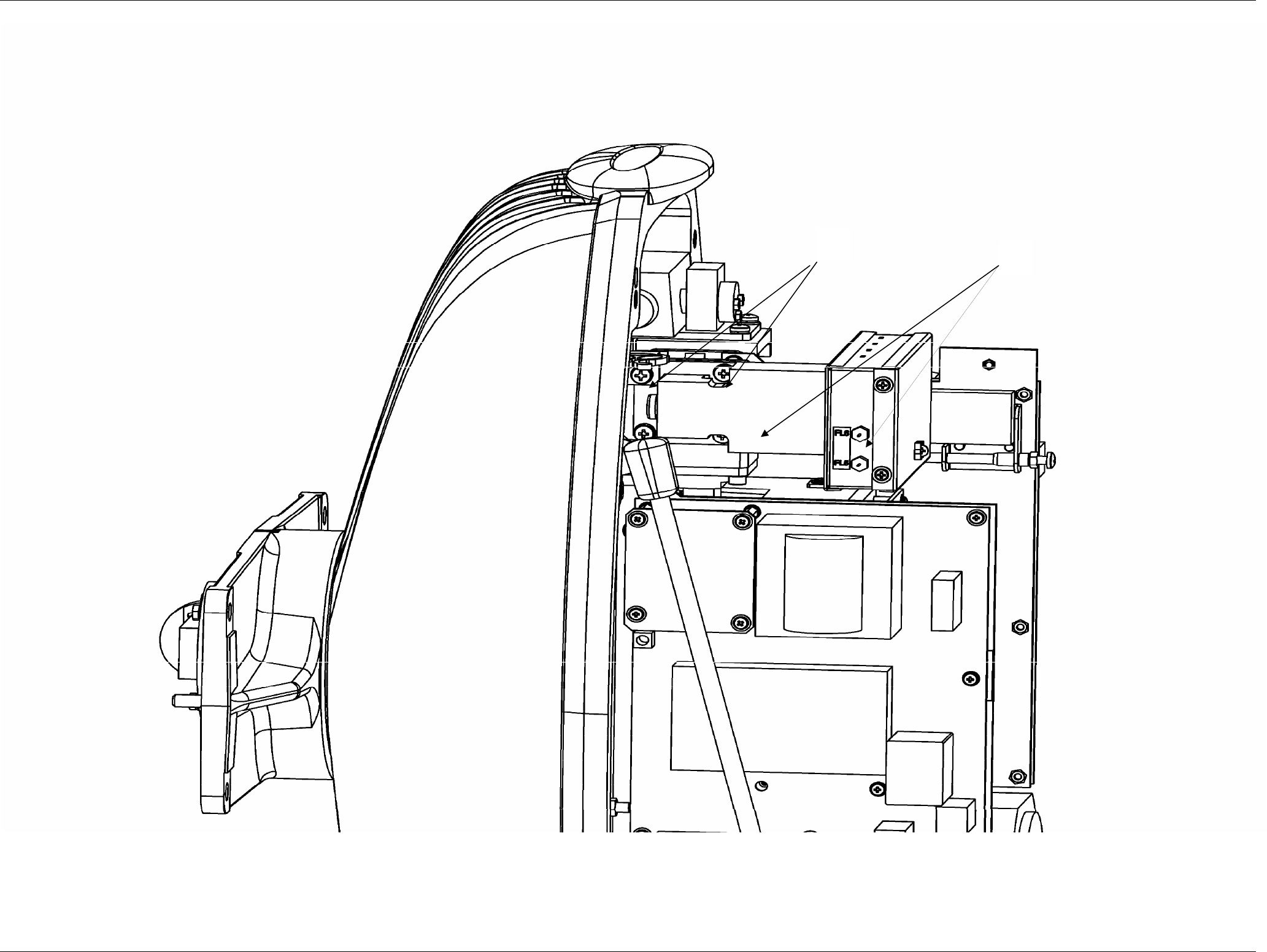
Figure 9.1.28 RF Amplifier
1
2
SRT X-BAND RADAR SYSTEMS
FIGURES
304202P003 9.31 Rev. C
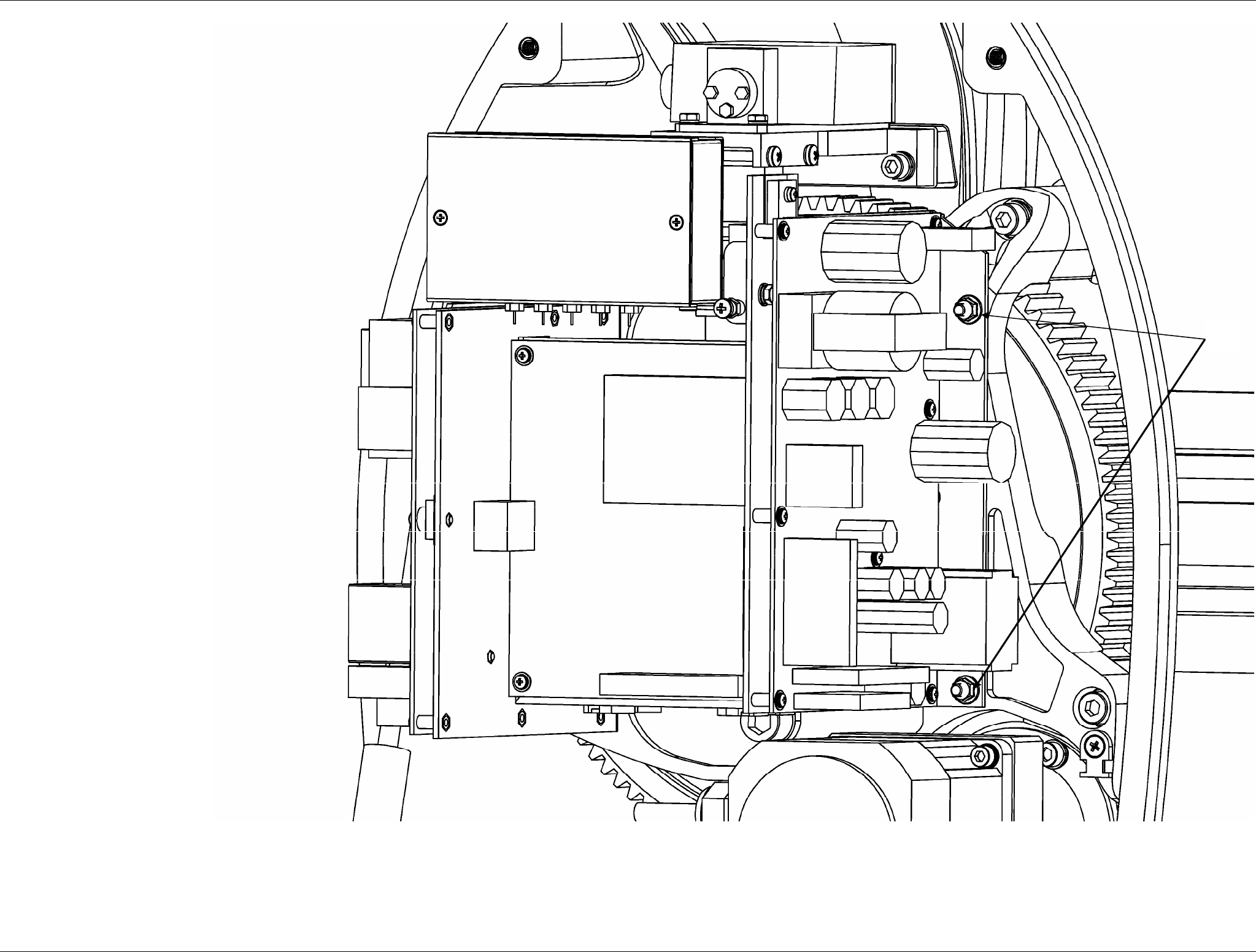
Figure 9.1.29 Electronics rack
1
SRT X-BAND RADAR SYSTEMS
FIGURES
304202P003 9.32 Rev. C
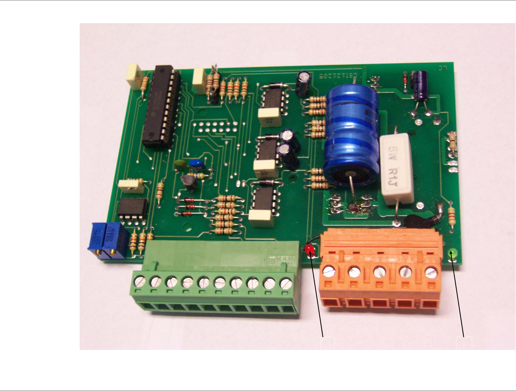
Figure 9.1.30 Bearing reader board
1 2
SRT X-BAND RADAR SYSTEMS
FIGURES
304202P003 9.33 Rev. C
Figure 9.1.31 Rotary joint
1
SRT X-BAND RADAR SYSTEMS
FIGURES
304202P003 9.34 Rev. C
Figure 9.1.32 Brushless Motor Controller
2 1
SRT X-BAND RADAR SYSTEMS
FIGURES
304202P003 9.35 Rev. C
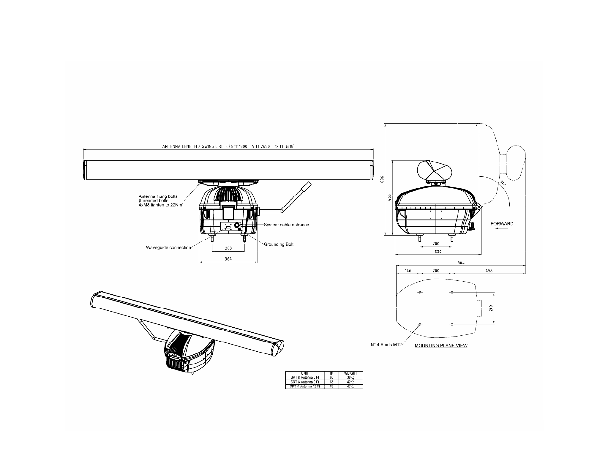
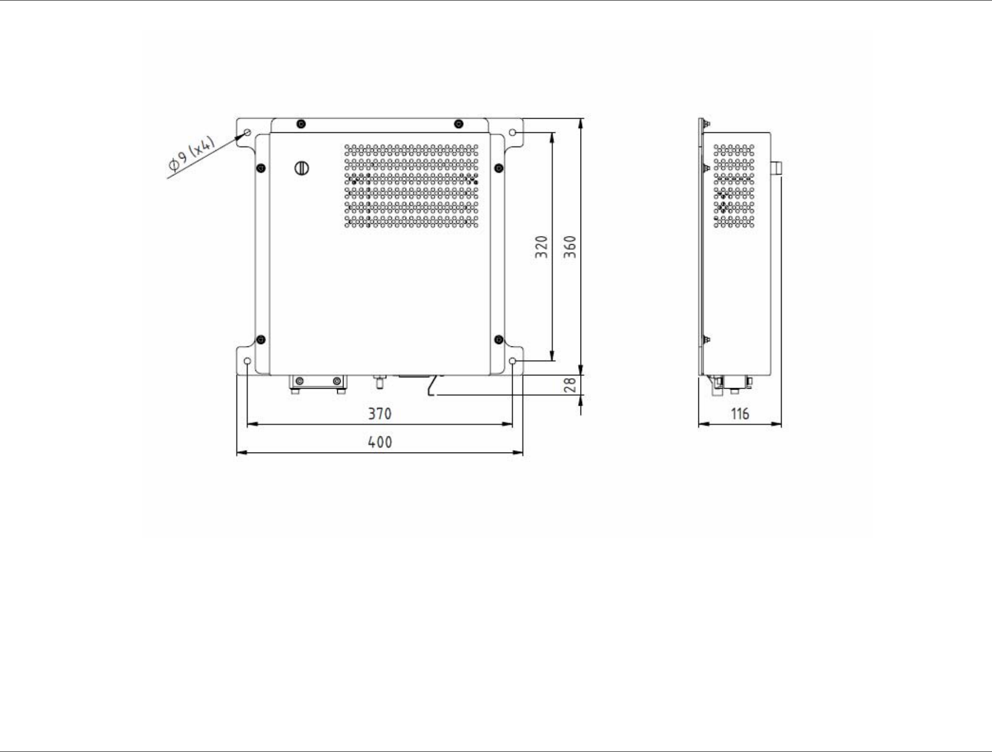
Figure 9.1.33 SRT Downmast Pedestal
dimensions drawing
SRT X-BAND RADAR SYSTEMS
FIGURES
304202P003 9.36 Rev. C
Figure 9.1.34 SRT Downmast Configuration Mechanical Assembly
1
2
SRT X-BAND RADAR SYSTEMS
FIGURES
304202P003 9.37 Rev. C
Figure 9.1.35 SRT Downmast Configuration Mechanical Assembly
1
2
3
SRT X-BAND RADAR SYSTEMS
FIGURES
304202P003 9.38 Rev. C
Figure 9.1.36 SRT Adapter Box