Contec FXE3000-US IEEE802.11n/a/b/g Wireless LAN Access Point Board User Manual FXE3000 US Setup Guide in English 20160629
Contec Co., Ltd. IEEE802.11n/a/b/g Wireless LAN Access Point Board FXE3000 US Setup Guide in English 20160629
Contec >
User manual
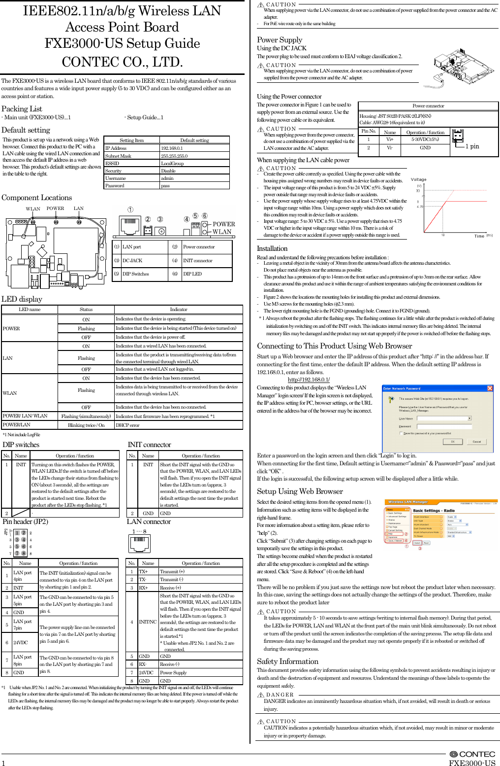
![FXE3000-US Setup Guide Specifications Name Specification Wired LAN Ethernet standard IEEE802.3(10BASE-T), IEEE802.3u(100BASE-TX) Port Speed / Communication type / Number of ports 10/100Mbps/Half Duplex, Full Duplex/ 1 Wireless LAN Wireless Networking Standard IEEE802.11n, IEEE802.11a, IEEE802.11b, IEEE802.11g Channel*1 USA (FCC) IEEE802.11n IEEE802.11a Access point 5GHz: 9ch(36, 40, 44, 48ch[W52] 149, 153, 157, 161, 165ch [W58] ) Station 5GHz: 21ch(36, 40, 44, 48ch[W52], 52, 56, 60, 64ch[W53], 100, 104, 108, 112, 116, 132, 136, 140ch[W56] 149, 153, 157, 161, 165ch [W58] ):] IEEE802.11n IEEE802.11g IEEE802.11b 2.4GHz: 11ch (1 - 11) IEEE802.11n Data transmission speed *2 300 - 6.5Mbps[MCS0 - 15, Short/Long GI] (Fixed/Auto) IEEE802.11a Data transmission speed *2 54, 48, 36, 24, 18, 12, 9, 6Mbps (Fixed/Auto) IEEE802.11b Data transmission speed *2 11, 5.5, 2, 1Mbps (Fixed/Auto) IEEE802.11g Data transmission speed *2 54, 48, 36, 24, 18, 12, 9, 6Mbps (Fixed/Auto) Security IEEE802.11n WPA(AES), WPA2(AES), WPA-PSK(AES), WPA2-PSK(AES), WSL(combination mentioned above are possible) IEEE802.11a/b/g WEP(open/ Shared Key /Auto), WPA(AES, TKIP), WPA-PSK(AES,TKIP), WPA2(AES, TKIP), WPA2-PSK(AES,TKIP), IEEE802.1X(EAP-TLS, PEAP), WSL(combination mentioned above are possible) Antenna chip-antenna×2 MIMO External dimension (mm) 60.0(W) x 89.2(D) x 17.5(H) Weight 50g *1 Varies depending on the country in which the product is used *2 These are theoretical values based on their respective wireless LAN standards; they do not indicate actual data transfer rates. Environmental Specifications Name Specification Input voltage range 5VDC±5% (DC Jack), 5 - 30VDC±5% (power connector), 24VDC±10% (PoE) Rating input current 0.83A (5VDC input), 0.15A (30VDC input) (Max.), 0.18A (PoE input 24V) Operating ambient temperature 0 - 50°C Operating ambient humidity 10 - 90%RH (No condensation) Floating dust particles Not extreme Corrosive gases None External Dimensions Precaution on use It is prohibited to modify the inside of this product. The product cannot be used in any country other than those authorized for use. Security Precautions Wireless LAN uses radio waves instead of LAN cables to send and receive data between a computer and a wireless access point, making it possible to freely establish a LAN connection within a range of the radio waves. However, radio waves can be received through obstacles, such as walls, when within the range. Therefore, if security settings are not made, the following problems may occur. Unauthorized viewing of data An unauthorized third party can intercept the radio waves and view e-mail messages and personal information, such as user ID and password or your credit card information. Unauthorized access An unauthorized third party can access a personal or corporate network and cause the following damage: - Intercepting personal information and confidential information (information leak) - Using a false identity to communicate and disclose information illegally (identity theft) - Changing and transmitting intercepted data (tampering) - Damaging data and systems by spreading a computer virus (destruction) The wireless LAN card and wireless access point have security features to counter these problems. Using the security settings of the wireless LAN equipment can help prevent these problems from occurring. The security settings of the wireless LAN equipment are not configured at the time of purchase. To reduce security problems, configure all security settings of the wireless LAN equipment according to the manual before using the wireless LAN card and wireless access point. Please be aware that the security settings do not provide complete security protection due to wireless LAN specifications. If you are unable to configure the security settings yourself, please contact your local authorized dealer. The customer is responsible for configuring the security settings and understanding the risks inherent in using the product without the security settings configured. Notes on Radio Interface The 2.4 GHz band used by this product covers the operating frequencies of mobile-identification local radio stations (requiring the license), specific low-power radio stations (requiring no license) and amateur wireless stations (requiring the license) as well as industrial, scientific, and medical equipment such as microwave ovens. 1. Before using this product, make sure that there is no mobile-identification local radio station, specific low-power radio station and amateur wireless station operating near the product. 2. If the product should cause radio interface with any mobile-identification local radio station or specific low-power radio station, immediately change the operating frequency to avoid the radio interface. 3. Placing wireless terminals near each other may slows down their data rate because of their mutual interference. You should allow a minimum clearance of about 1m between stations, 3m between access point and station, and 3m between access points. 4. Contact your local retailer or CONTEC if the product has trouble such as recurrent radio interface with mobile-identification local radio stations or specific low-power radio stations About the speed mark The link speed shown for the transmission rate in this manual, the setup screens, and elsewhere is the theoretical maximum value based on the wireless LAN standard and does not represent the actual data transfer rate. Usage limitation This product has not been developed or manufactured to be used in systems including the equipment which is directly related to human lives *1 or the equipment which involves human safety and may significantly affect the maintenance of public functions *2. Therefore, do not use the product for such purposes. In addition, do not use the product within 20cm from a human body on a regular basis. *1: Medical devices such as life-support equipment and devices used in an operating theater. *2: Main control systems at nuclear power stations, safety maintenance systems at nuclear facilities, other important safety-related systems, operation control systems within group transport systems, air-traffic control systems, etc. If using the IEEE802.11a standard, ensure that you comply with all relevant laws in the country of use. Outdoor use of IEEE802.11a is prohibited in some countries. It is not possible to use it by limiting Radio Law in Japan. Handling Precautions Do not use the product where it is exposed to flammable or corrosive gas. Doing so may result in an explosion, fire, electric shock, or failure. - This product contains precision electronic elements and must not be used in locations subject to physical shock or strong vibration. Otherwise, the board may malfunction, overheat, or cause a failure. - Do not use or store this device in high temperature or low temperature surroundings, or do not expose it to extreme temperature changes. Otherwise, the board may malfunction, overheat, or cause a failure. - Do not use or store this device where it is exposed to direct sunlight or near stoves or other sources of heat. Otherwise, the board may malfunction, overheat, or cause a failure. - Do not use or store this device near strong magnetic fields or devices emitting electromagnetic radiation. Otherwise, the board may malfunction, overheat, or cause a failure. - If an unusual smell or overheat is noticed, unplug the power cable immediately In the event of an abnormal condition or malfunction, please contact your retailer. - The specifications of this product are subject to change without notice for enhancement and quality improvement. Even when using the product continuously, be sure to read the manual and understand the contents. - Do not attempt to modify this device. The manufacturer will bear no responsibility whatsoever for the device if it has been modified. - The product must always be associated with the instruction manual. - Regardless of the foregoing statements, CONTEC is not liable for any damages whatsoever (including damages for loss of business profits) arising out of the use or inability to use this CONTEC product or the information contained herein. Federal Communications Commission FCC Caution: Changes or modifications not expressly approved by the party responsible for compliance could void the user's authority to operate this equipment. Note: This equipment has been tested and found to comply with the limits for a Class A digital device, pursuant to part 15 of the FCC Rules. These limits are designed to provide reasonable protection against harmful interference when the equipment is operated in a commercial environment. This equipment generates, uses, and can radiate radio frequency energy and, if not installed and used in accordance with the instruction manual, may cause harmful interference to radio communications. Operation of this equipment in a residential area is likely to cause harmful interference in which case the user will be required to correct the interference at his own expense. Data transmission is always initiated by software, which is the passed down through the MAC, through the digital and analog baseband, and finally to the RF chip. Several special packets are initiated by the MAC. These are the only ways the digital baseband portion will turn on the RF transmitter, which it then turns off at the end of the packet. Therefore, the transmitter will be on only while one of the aforementioned packets is being transmitted. In other words, this device automatically discontinue transmission in case of either absence of information to transmit or operational failure. Frequency Tolerance: 20ppm This transmitter must not be co-located or operated in conjunction with any other antenna or transmitter. This equipment complies with FCC/IC radiation exposure limits set forth for an uncontrolled environment and meets the FCC radio frequency (RF) Exposure Guidelines and RSS-102 of the IC radio frequency (RF) Exposure rules. This equipment should be installed and operated keeping the radiator at least 20cm or more away from person’s body. End Product Labeling this transmitter module is authorized only for use in device where the antenna may be installed such that 20 cm may be maintained between the antenna and users. The final end product must be labeled in a visible area with the following: “Contains FCC ID: PQRFXE3000-US”. The grantee's FCC ID can be used only when all FCC compliance requirements are met. Users in Canada Contains Transmitter Module IC: XXXXXX-YYYYYYYYYYY This device complies with Industry Canada’s license-exempt RSSs. Operation is subject to the following two conditions:(1) This device may not cause interference; and (2) This device must accept any interference, including interference that may cause undesired operation of the device. This radio transmitter (IC Number(XXXXXX-YYYYYYYYYYY) identify the device by certification number or model number if Category II) has been approved by Industry Canada to operate with the antenna types listed below with the maximum permissible gain indicated. Antenna types not included in this list, having a gain greater than the maximum gain indicated for that type, are strictly prohibited for use with this device. Antenna Name Antenna Type Peak Gain(dBi) FX-ANT-A8 CHIP 4 FXE3000-ANT CHIP 4 MR-1700-W Vehicle 4 MPR-6000 Vehicle 4 5150-5250 MHz band is restricted to indoor operation only. High-power radars are allocated as primary users (i.e. priority users) of the bands 5250-5350 MHz and 5650-5850 MHz and that these radars could cause interference and/or damage to LE-LAN devices. Compliance with IC requirement RSS-210 A9.4.4 Data transmission is always initiated by software, which is the passed down through the MAC, through the digital and analog baseband, and finally to the RF chip. Several special packets are initiated by the MAC. These are the only ways the digital baseband portion will turn on the RF transmitter, which it then turns off at the end of the packet. Therefore, the transmitter will be on only while one of the aforementioned packets is being transmitted. In other words, this device automatically discontinue transmission in case of either absence of information to transmit or operational failure. CONTEC CO.,LTD. 3-9-31, Himesato, Nishiyodogawa-ku, Osaka 555-0025, Japan January2016Edition Japanese http://www.contec.co.jp/ English http://www.contec.com/ Chinese http://www.contec.com.cn/ NA04034(LYSM171)[18012016]No part of this document may be copied or reproduced in any form by any means without prior written consent of CONTEC CO., LTD. 4-φ3.58289.23.66032.224.2D A N G E RC A U TIO N](https://usermanual.wiki/Contec/FXE3000-US/User-Guide-3074814-Page-2.png)