Continental Automotive Systems SMK27 Smart Key ECU User Manual for SMK2 7 Rev1
Continental Automotive Systems Corporation Smart Key ECU for SMK2 7 Rev1
User manual
.
Proprietary data, company confidential. All rights reserved.
Confié à titre de secret d'entreprise. Tous droits réservés.
Comunicado como segredo empresarial. Reservados todos os direitos.
Confidado como secreto industrial. Nos reservamos todos los derechos.
.
.
Weitergabe sowie Vervielfältigung dieser Unterlage, Ver
-
wertung und Mitteilung ihres Inhalts nicht gestattet, soweit
nicht ausdrücklich zugestanden. Zuwiderhandlungen ver
-
pflichten zu Schadenersatz. Alle Rechte vorbehalten, insbe
-
sondere für den Fall der Patenterteilung oder GM-Eintragung
.
.
Identification No. :
Document : User Manual for SMK2.7
Project : SMK2.7
Project Code :
Version: 0.1
Date: Aug. 26 '11
Engineering change order-No.:
Design Freeze No.:
Number of pages: 12
Filename: User Manual for SMK2.7

Editor : CU Jun Document name Project code
Version: 0.1 Aug. 26. 2011
ECO / DF No.
Identification No. : Document No.
File: User Manual for SMK2.7 Rev1.doc Page 2 / 12
.
Proprietary data, company confidential. All rights reserved.
Confié à titre de secret d'entreprise. Tous droits réservés.
Comunicado como segredo empresarial. Reservados todos os direitos.
Confidado como secreto industrial. Nos reservamos todos los derechos.
.
.
Weitergabe sowie Vervielfältigung dieser Unterlage, Ver
-
wertung und Mitteilung ihres Inhalts nicht gestattet, soweit
nicht ausdrücklich zugestanden. Zuwiderhandlungen ver
-
pflichten zu Schadenersatz. Alle Rechte vorbehalten, insbe
-
sondere für den Fall der Patenterteilung oder GM-Eintragung
.
.
Contents list Page
1. System configulation 3
1.1 Scope of SMART KEY SYSTEM 3
1.2 short description of the SYSTEM 3
1.2.1 General Definition of SMART KEY 3
1.2.2 Wireless Communication 3
1.2.3 Concept Description 4
1.2.4 System Architecture 4
1.2.5 Main Functions 5
1.3 System Overview / Block Diagram 6
2. SMK2.7 Configuration 8
2.1 Block Diagram 8
2.2 Pin Description 9
2.3 SMK2.7 ECU 11
3 SMK 2.7 ECU Test Board for homologation 12
3.1 Shape of tool box 12
3.2 Switch 12
3.3 Method to use Test board 12

Editor : CU Jun Document name Project code
Version: 0.1 Aug. 26. 2011
ECO / DF No.
Identification No. : Document No.
File: User Manual for SMK2.7 Rev1.doc Page 3 / 12
.
Proprietary data, company confidential. All rights reserved.
Confié à titre de secret d'entreprise. Tous droits réservés.
Comunicado como segredo empresarial. Reservados todos os direitos.
Confidado como secreto industrial. Nos reservamos todos los derechos.
.
.
Weitergabe sowie Vervielfältigung dieser Unterlage, Ver
-
wertung und Mitteilung ihres Inhalts nicht gestattet, soweit
nicht ausdrücklich zugestanden. Zuwiderhandlungen ver
-
pflichten zu Schadenersatz. Alle Rechte vorbehalten, insbe
-
sondere für den Fall der Patenterteilung oder GM-Eintragung
.
.
1. System configulation
1.1 Scope of SMART KEY SYSTEM
The System offers the following features:
passive access to two doors and trunk; driver side, passenger side, and trunk/tailgate
passive start after interior detection of the SMART KEY FOB
(without interior trunk detection)
LF-RF communication (based on Continental’s SMART KEY system)
passive access/locking of the two front doors via a toggle push button in the door
handles
passive access trunk/tailgate via the trunk lid switch at the trunk
immobilizer backup solution integrated into SMK 2.7
communication to the engine management system via a single line interface
communication to the ESCL via a single line interface
block of the steering column by the ESCL device
1.2 short description of the SYSTEM
1.2.1 General Definition of SMART KEY
The SMART KEY system is a system that allows the user to access and operate a
vehicle in a very convenient way. To access the vehicle, no traditional key or remote
control unit is needed.
The SMART KEY system is triggered by pressing a push button in the door handle.
After triggered, the vehicle sends out a request in a limited range. If the SMART KEY
FOB receives this request, SMART KEY FOB automatically sends a response to the
vehicle. Then the system decides whether to perform a particular action (unlocking,
locking…) or to remain inactive.
In a similar manner, the SMART KEY system is triggered by pressing a start-stop
button in the dash board.
After triggered, the vehicle sends out a request in a limited range(especially interior
region). If the SMART KEY FOB receives this request, SMART KEY FOB
automatically sends a response to the vehicle. Then the system decides whether to
perform a particular action (terminal status change…) or to remain inactive.
1.2.2 Wireless Communication
Electromagnetic waves are used to exchange information between the vehicle and the
SMART KEY FOB. Both, vehicle and SMART KEY FOB are equipped with a transmitter,
a receiver and several antennas.

Editor : CU Jun Document name Project code
Version: 0.1 Aug. 26. 2011
ECO / DF No.
Identification No. : Document No.
File: User Manual for SMK2.7 Rev1.doc Page 4 / 12
.
Proprietary data, company confidential. All rights reserved.
Confié à titre de secret d'entreprise. Tous droits réservés.
Comunicado como segredo empresarial. Reservados todos os direitos.
Confidado como secreto industrial. Nos reservamos todos los derechos.
.
.
Weitergabe sowie Vervielfältigung dieser Unterlage, Ver
-
wertung und Mitteilung ihres Inhalts nicht gestattet, soweit
nicht ausdrücklich zugestanden. Zuwiderhandlungen ver
-
pflichten zu Schadenersatz. Alle Rechte vorbehalten, insbe
-
sondere für den Fall der Patenterteilung oder GM-Eintragung
.
.
1.2.3 Concept Description
With this concept it is possible to have a set of interior antennas that cover the vehicle’s
interior and a set of exterior antennas that cover the vehicle’s exterior.
For an unambiguous separation between the vehicle’s interior and exterior it is sufficient
that at least one area is covered exactly by the corresponding operating ranges of the
antennas.
The functions of the SMART KEY system have to be provided in a clearly defined and
limited range. For the up-link from the vehicle to the SMART KEY FOB, a magnetic field
with a frequency of 125 kHz and ASK modulation is used.
Technical aspects of 125 kHz – magnetic field:
virtually no reflections,
cubical decrease of field strength allows good range control,
released frequency band (ISM),
high penetration,
low quiescent current demand due to 125 kHz input stage (SMART KEY FOB),
less sensitive for detuning compared to higher frequency.
For the down-link from the SMART KEY FOB to the vehicle, the standard radio frequency
(RF) is used (similar to the classic remote control functions) with FSK modulation.
1.2.4 System Architecture
The system is designed as an optional system, making it possible to equip vehicles of the
same car-Line with different levels of access control systems.
The system is suitable to be integrated into an existing architecture that provides central
locking functions with standard remote control. This proposal assumes that the following
functions / devices are already present in the vehicle’s architecture.
Central locking system (latch / motor – drivers etc.)
Standard body control functions
Warning buzzer
Editor : CU Jun Document name Project code
Version: 0.1 Aug. 26. 2011
ECO / DF No.
Identification No. : Document No.
File: User Manual for SMK2.7 Rev1.doc Page 5 / 12
.
Proprietary data, company confidential. All rights reserved.
Confié à titre de secret d'entreprise. Tous droits réservés.
Comunicado como segredo empresarial. Reservados todos os direitos.
Confidado como secreto industrial. Nos reservamos todos los derechos.
.
.
Weitergabe sowie Vervielfältigung dieser Unterlage, Ver
-
wertung und Mitteilung ihres Inhalts nicht gestattet, soweit
nicht ausdrücklich zugestanden. Zuwiderhandlungen ver
-
pflichten zu Schadenersatz. Alle Rechte vorbehalten, insbe
-
sondere für den Fall der Patenterteilung oder GM-Eintragung
.
.
1.2.5 Main Functions
The system allows the user to access and exit (unlock and lock) the vehicle without
performing any actions with the SMART KEY FOB.
The system allows the user to control ESCL lock/unlock, to operate relaies to provide
power(Off, Accessory, Ignition) to other ECU, and to start/stop the vehicle’s engine
without performing any actions with the SMART KEY FOB.
Additionally, the system offers the user can operate all vehicle functions by contacting
the Fob to the Start/stop button, which have Immobilizer antenna(terminal control
fuction), and by inserting the mechanical key blade into the door handle(Passive
access function).
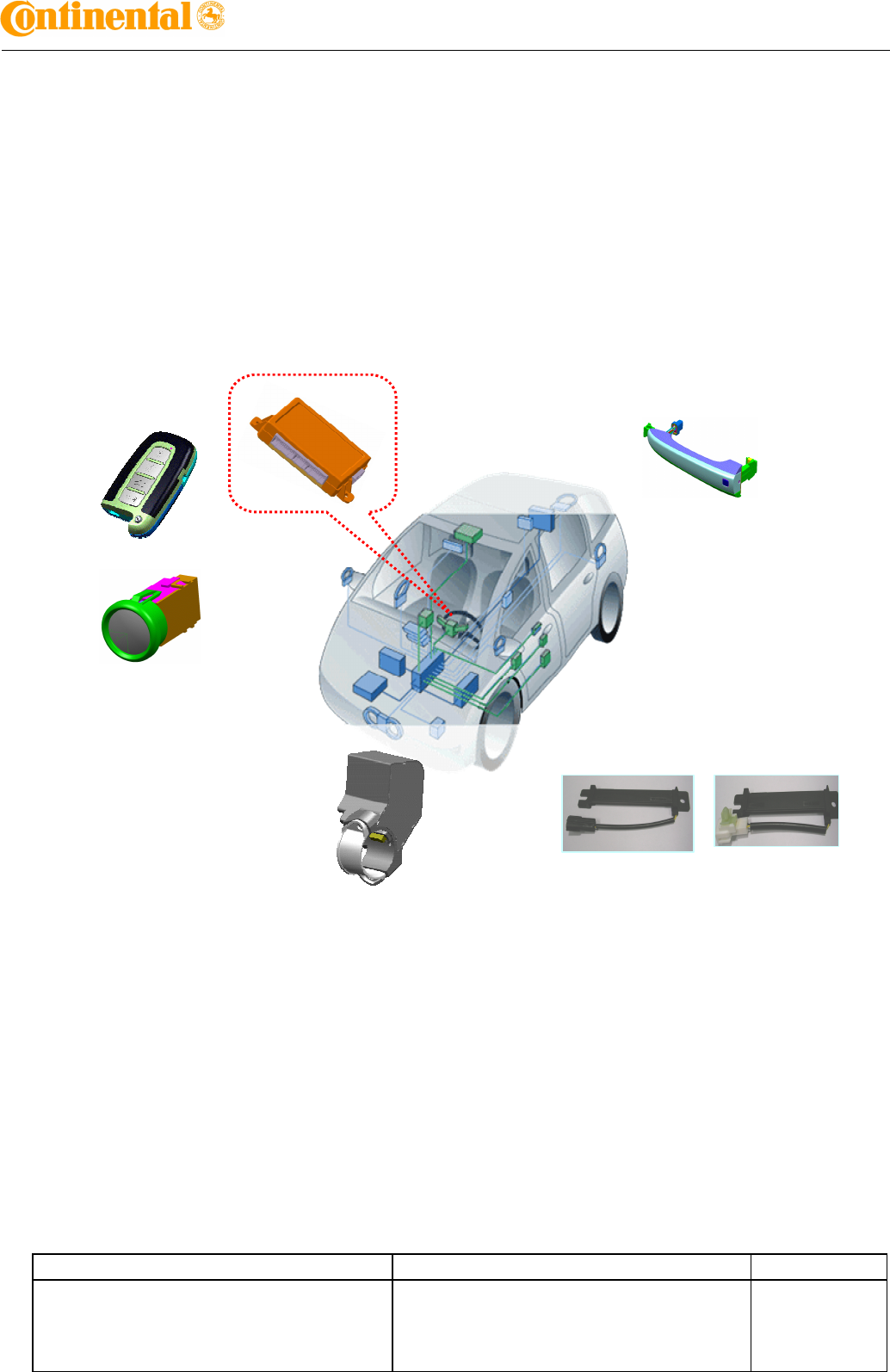
Figure 1: Offered System Components
FOB Key
LF Antenna
SMK2.
7
Start Stop Button
(Immobilizer Antenna included)
ESCL
DH : 안테나 코일 housing
Editor : CU Jun Document name Project code
Version: 0.1 Aug. 26. 2011
ECO / DF No.
Identification No. : Document No.
File: User Manual for SMK2.7 Rev1.doc Page 6 / 12
.
Proprietary data, company confidential. All rights reserved.
Confié à titre de secret d'entreprise. Tous droits réservés.
Comunicado como segredo empresarial. Reservados todos os direitos.
Confidado como secreto industrial. Nos reservamos todos los derechos.
.
.
Weitergabe sowie Vervielfältigung dieser Unterlage, Ver
-
wertung und Mitteilung ihres Inhalts nicht gestattet, soweit
nicht ausdrücklich zugestanden. Zuwiderhandlungen ver
-
pflichten zu Schadenersatz. Alle Rechte vorbehalten, insbe
-
sondere für den Fall der Patenterteilung oder GM-Eintragung
.
.
1.3 System Overview / Block Diagram
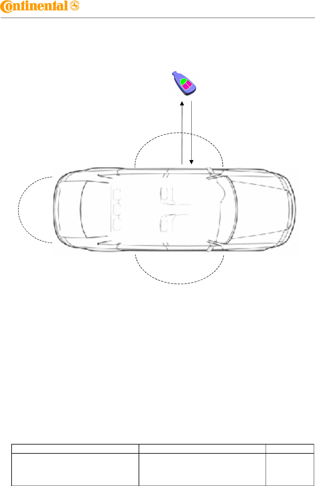
Figure 2: Principle of Communication
Challenge
(LF-Up-link)
Response
(RF-Down-link)
SMART KEY FOB
Passive Access
Detection Range
Passive Access
Detection Range
Editor : CU Jun Document name Project code
Version: 0.1 Aug. 26. 2011
ECO / DF No.
Identification No. : Document No.
File: User Manual for SMK2.7 Rev1.doc Page 9 / 12
.
Proprietary data, company confidential. All rights reserved.
Confié à titre de secret d'entreprise. Tous droits réservés.
Comunicado como segredo empresarial. Reservados todos os direitos.
Confidado como secreto industrial. Nos reservamos todos los derechos.
.
.
Weitergabe sowie Vervielfältigung dieser Unterlage, Ver
-
wertung und Mitteilung ihres Inhalts nicht gestattet, soweit
nicht ausdrücklich zugestanden. Zuwiderhandlungen ver
-
pflichten zu Schadenersatz. Alle Rechte vorbehalten, insbe
-
sondere für den Fall der Patenterteilung oder GM-Eintragung
.
.
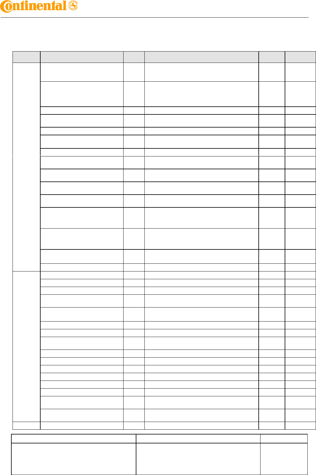
2.2 Pin Description
Function I/O Connect
or No Description Type Remarks
Analog
Input
VBAT_CPU A14 Supply power to SMK 2.7
VBAT_CPU(Battery voltage) monitoring signal
input
Pull down
VBAT_LOAD A1
Supply power to terminal control relay/
backup supply to SMK 2.7
VBAT_LOAD(Battery voltage) monitoring
signal input
Pull down
- - VBD voltage monitoring signal input Pull down
- - SSUR(Software Step-Up Regulator) output
voltage feedback monitoring signal input Pull down
A_ACC A6 Accessory voltage monitoring signal input Pull down
A_IGN1 A4 Ignition1 voltage monitoring signal input/
Supply power to starter relay output
Pull down
A_IGN2 A7 Ignition2 voltage monitoring signal input Pull down
O_ACC_RLY A19 Accessory relay control output diagnosis
signal input -
O_STARTER_RLY A17 Starter relay control output diagnosis signal
input -
O_IGN1_RLY A5 Ignition1 relay control output diagnosis signal
input -
O_IGN2_RLY A18 Ignition2 relay control output diagnosis signal
input -
O_ESCL_BAT A15
ESCL(Electronic Steering Column Lock
)
power supply output diagnosis signal
input
-ESCL
option
O_ESCL_GND A2
ESCL(Electronic Steering Column Lock
)
ground supply output diagnosis signal
input
-ESCL
option
O_ESCLEnable B7 ESCL(Electronic Steering Column Lock)
Enable output diagnosis signal input
-ESCL
option
A_RESERVE A20 Reserved analog signal input Pull down RESERVE
Logic
Input
L_SSB_SW1 A25 Starter Stop Button switch1 signal input Pull up
L_SSB_SW2 A8 Starter Stop Button switch2 signal input Pull up
L_DRVToggle Button B9 Driver door toggle button switch signal input Pull up
L_ASTToggle Button A26 Assistant door toggle button switch signal
input Pull up
L_ESCLUnlock B10 Unlock signal input for ESCL(Electronic
Steering Column Lock)Pull up ESCL
option
L_BrakeSW B5 Brake pedal pressing signal input Pull down
L_StopLampFuse B4 Stop lamp fuse failure detection signal input Pull down
L_StartFeedback B13 Parking/ Neutral (P/N) inhibit start switch
acquisition signal input Pull down
L_PPosition B12 Parking Position signal input Pull up
L_TrunkLidSW A21 Trunk Lid switch signal input Pull up
L_AST_capa_sensor C17 Assistant capa sensor signal input Pull up
L_DRV_capa sensor C6 Driver capa sensor signal input Pull up
L_RAST_capa_sensor C14 Rear assistant capa sensor signal input Pull up
L_RDRV_capa_sensor B3 Rear driver capa sensor signal input Pull up
L_RASTToggle Button A22 Rear assistant door toggle button switch
signal input Pull up
L_RDRVToggle Button A9 Rear driver door toggle button switch signal
input Pull up
Output O_ACC_RLY A19 Accessory relay control output High side
Editor : CU Jun Document name Project code
Version: 0.1 Aug. 26. 2011
ECO / DF No.
Identification No. : Document No.
File: User Manual for SMK2.7 Rev1.doc Page 10 / 12
.
Proprietary data, company confidential. All rights reserved.
Confié à titre de secret d'entreprise. Tous droits réservés.
Comunicado como segredo empresarial. Reservados todos os direitos.
Confidado como secreto industrial. Nos reservamos todos los derechos.
.
.
Weitergabe sowie Vervielfältigung dieser Unterlage, Ver
-
wertung und Mitteilung ihres Inhalts nicht gestattet, soweit
nicht ausdrücklich zugestanden. Zuwiderhandlungen ver
-
pflichten zu Schadenersatz. Alle Rechte vorbehalten, insbe
-
sondere für den Fall der Patenterteilung oder GM-Eintragung
.
.
O_STARTER_RLY A17 Starter relay control output High side
O_IGN1_RLY A5 Ignition1 relay control output High side
O_IGN2_RLY A18 Ignition2 relay control output High side
O_ESCL_BAT A15 ESCL Electronic Steering Column Lock)
power source control output High side ESCL
option
O_ESCL_GND A2 Ground source supply for ESCL(Electronic
Steering Column Lock)Low side ESCL
option
O_ESCLEnable B7 ESCL(Electronic Steering Column Lock)
Enable control output High side ESCL
option
O_SSB_ILLUM_PWR C13 Starter Stop Button illumination power source
output High side
O_SSB_ILLUM_GND C1 Starter Stop Button illuminatio
n ground source
output Low side
O_SSB_LED_AMBER/ACC B16 Starter Stop Button AMBER/ACC LED output Low side
O_SSB_LED_BLUE/IGN C12 Starter Stop Button BLUE/IGN LED output Low side
O_SSB_LED_OFF C3 Starter Stop Button OFF LED output Low side
O_IMMO_IND C2 IMMO indicator LED output Low side
O_EXTERIOR_BUZZER B11 Exterior Buzzer control output High side
VS F_WheelSpeed B8 Vehicle Speed data input from brake system
RPM F_RPM A23 RPM frequency data input from EMS
LF
Antenna
Output
O_DRV_SIDE_ANTENNA_pwr C11 Driver side antenna power output
O_DRV_SIDE_ANTENNA_gnd C22 Driver side antenna power ground
O_AST_SIDE_ANTENNA_pwr C10 Assistant side antenna power output
O_AST_SIDE_ANTENNA_gnd C21 Assistant side antenna power ground
O_BUMPER_ANTENNA_pwr C9 Bumper antenna power output
O_BUMPER_ANTENNA_gnd C20 Bumper antenna power ground
O_TRUNK_ANTENNA_pwr C8 Trunk antenna power output
O_TRUNK_ANTENNA_gnd C19 Trunk antenna power ground
O_INTERIOR_ANTENNA#1_pwr C5 Interior Antenna#1 power output
O_INTERIOR_ANTENNA#1_gnd C16 Interior Antenna#1 power ground
O_INTERIOR_ANTENNA#2_pwr C4 Interior Antenna#2 power output
O_INTERIOR_ANTENNA#2_gnd C15 Interior Antenna#2 power ground
O_HATSHELF_ANTENNA_pwr C7 hatshelf Antenna power output
O_HATSHELF_ANTENNA_gnd C18 hatshelf Antenna power ground
Immo Ant.
Output
O_IMMO_ANT_pwr B6 O_IMMO Antenna power output
O_IMMO_ANT_gnd B14 O_IMMO Antenna power ground output
High
speed
CAN
C_CAN_H B2 High speed CAN network communication
line(high)
C_CAN_L B1 High speed CAN network communication
line(low)
Low
speed
CAN
B_CAN_H A12 Low speed CAN network communication
line(high)
B_CAN_L A13 Low speed CAN network communication
line(low)
EMS Com EMS_COM A24 EMS(Engine Management System)
communication line
ESCL
Com. ESCL_COM A11 ESCL(Electronic Steering Column Lock)
communication line ESCL
option
Diagnostic DIAG_K B15 Diagnostic Communication line K for Tester
RF Com. RF_COM A10 RF Communication line
Ground POWER_GND1 A3 Power ground1
POWER_GND2 A16 Power ground2

Editor : CU Jun Document name Project code
Version: 0.1 Aug. 26. 2011
ECO / DF No.
Identification No. : Document No.
File: User Manual for SMK2.7 Rev1.doc Page 11 / 12
.
Proprietary data, company confidential. All rights reserved.
Confié à titre de secret d'entreprise. Tous droits réservés.
Comunicado como segredo empresarial. Reservados todos os direitos.
Confidado como secreto industrial. Nos reservamos todos los derechos.
.
.
Weitergabe sowie Vervielfältigung dieser Unterlage, Ver
-
wertung und Mitteilung ihres Inhalts nicht gestattet, soweit
nicht ausdrücklich zugestanden. Zuwiderhandlungen ver
-
pflichten zu Schadenersatz. Alle Rechte vorbehalten, insbe
-
sondere für den Fall der Patenterteilung oder GM-Eintragung
.
.
2.3 SMK2.7 ECU
SMK 2.7 ECU manages all functions related to “Passive Access”, “Passive Unlocking” ,
“Passive Authorization for Operation”, "Terminal control" .
SMK 2.7 ECU reads the inputs (Door Lock/unlock, SSB SW, ESCL unlock status,
PARK position Switch, Brake input SW etc.), controls the outputs (e.g. exterior or
interior antennas, terminal control output, ESCL power, Immobilizer antenna), and
communicates via the CAN/LIN (depends on the vehicle) as well as a single line
interface to further devices of the car.
For the communication with the SMART KEY FOB, SMK 2.7 ECU generates a request
(challenge) as an encoded and modulated 125 kHz signal at the inductive antenna
outputs and receives the SMART KEY FOB’s response via the external RF receiver.
Or for immobilizer communicaiton, SMK 2.7 ECU sends 125Khz LF signal to SSB's
immobilizer antenna, and receives Response from Immobilizer antenna.
The main functional blocks of the SMK 2.7 ECU are:
Power supply
Microcontroller with FLASH Memory
Single Line Interface to ESCL
Single Line Interface to EMS
Input stage
LF antenna amplifier/driver
Immobilizer Antenna output
ESCL power supply
Terminal Control(ACC, IGN1/2, Start Rly)
CAN communication with Other ECU
Immobilizer communication
The LF antenna amplifier/driver generates a 125 kHz sinusoidal carrier signal, which is
distributed to the different antennas.
The signal for Interior antenna and exterior antenna is 100%-ASK modulated by
switching on and off the carrier (the data is Manchester encoded). The power of the
carrier is adjustable by software, which means, it is possible to set the power level of
the antenna driver for every LF-telegram (e.g. power level stored in the EEPROM) in
case of PASE LF Antenna.
And also the signal for immobilizer antenna is ASK modulated signal. Amplitude Shift
Keying for write and AM/PM for the read operation. The receiver charteristics(amplifier
gain, filter cutoff frequencies) can be optimized to system and transponder
requirements.
Editor : CU Jun Document name Project code
Version: 0.1 Aug. 26. 2011
ECO / DF No.
Identification No. : Document No.
File: User Manual for SMK2.7 Rev1.doc Page 12 / 12
.
Proprietary data, company confidential. All rights reserved.
Confié à titre de secret d'entreprise. Tous droits réservés.
Comunicado como segredo empresarial. Reservados todos os direitos.
Confidado como secreto industrial. Nos reservamos todos los derechos.
.
.
Weitergabe sowie Vervielfältigung dieser Unterlage, Ver
-
wertung und Mitteilung ihres Inhalts nicht gestattet, soweit
nicht ausdrücklich zugestanden. Zuwiderhandlungen ver
-
pflichten zu Schadenersatz. Alle Rechte vorbehalten, insbe
-
sondere für den Fall der Patenterteilung oder GM-Eintragung
.
.
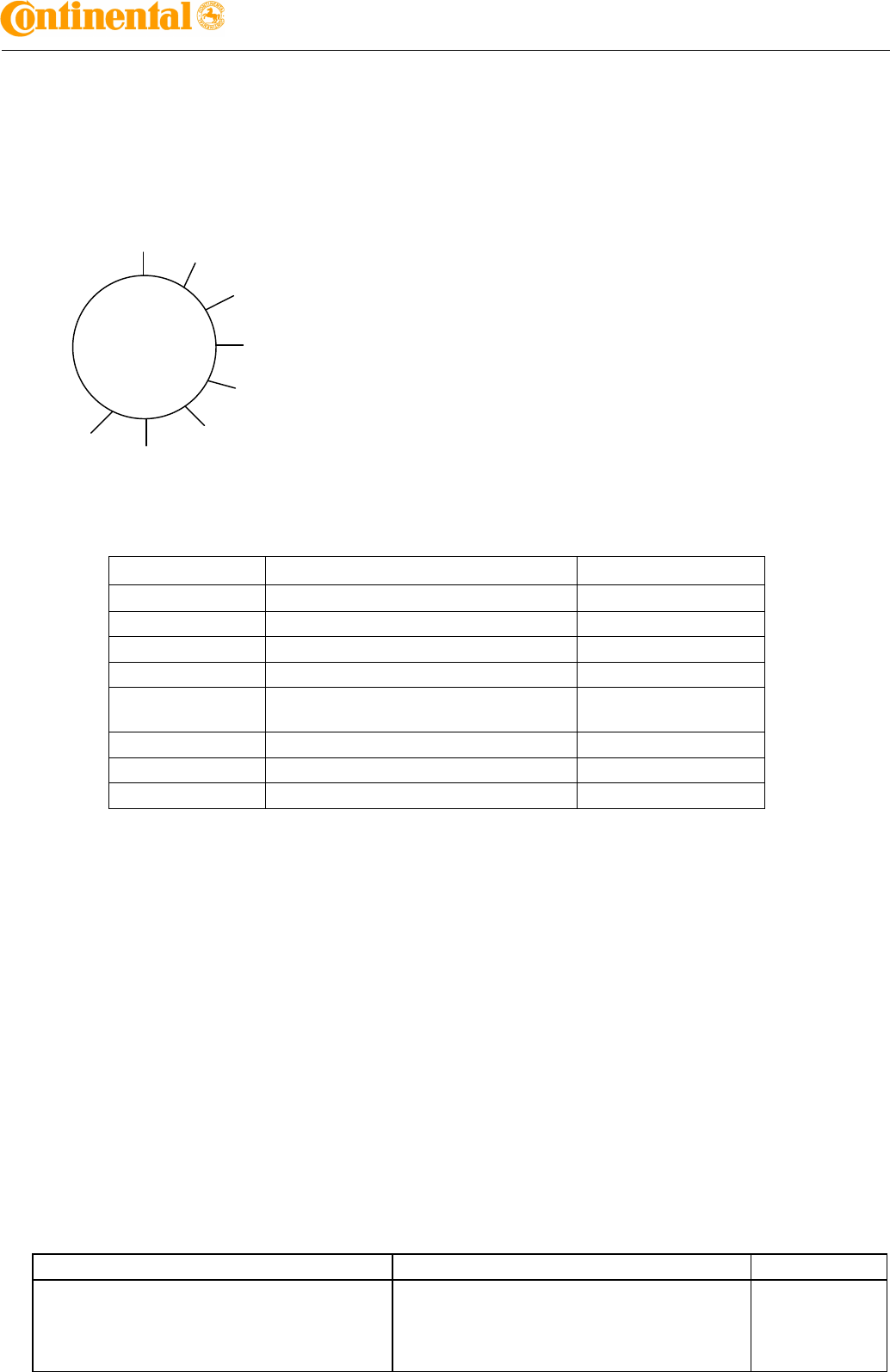
3 SMK 2.7 ECU Test Board for homologation
3.1 Shape of tool box
OFF 1
2
3
4
5
6
7
3.2 Switch
No. Output Remark
OFF ALL ANTENNA OUTPUT OFF
1 DRV ANTENNA OUTPUT
2 AST ANTENNA OUTPUT
3 BUMPER ANTENNA OUTPUT
4 INTERIOR1 ANTENNA OUTPUT
INTERIOR2 ANTENNA OUTPUT
5 HATSHELF ANTENNA OUTPUT
6 TRUNK ANTENNA OUTPUT
7 IMMO ANTENNA OUTPUT
3.3 Method to use Test board
- Prepare VB, GND wire to connect Tool Box.
- Connect Power(VB, GND) to Tool Box.
- Connect Harness connector to SMK ECU Unit.
- After selecting swich No. , give VB power to test board.(Do not give overvoltage)