Continental Automotive DHSNFC Door Handle Sensor NFC User Manual Manual of user
Continental Automotive GmbH Door Handle Sensor NFC Manual of user
Manual of user
AuD5 NFC : product overview – usage for homologation
Date
Department
Designed by
Released by
Designation
IMS ID
161711
SAP ID
10 348616
Document version as of
April 27, 2017
Pages
1 of 33
Transmittal, reproduction, dissemination and/or editing of this document as well as utilization of its contents and communication thereof to others without express authorization are prohibited.
Offenders will be held liable for payment of damages. All rights created by patent grant or registration of a utility model or design patent are reserved.
Purpose: Door Handle Sensor - Audi D5 NFC
Scope:
Product name
Variant
Continental Part number
Audi Part number
DHS Audi D5 NFC - L
NFC Left
A2C 114 793
4N1.927.753
DHS Audi D5 NFC - R
NFC Right
A2C 114 797
4N1.927.754
Door Handle Sensor Audi D5 NFC
-
product overview – usage for homologation
Version AA
AuD5 NFC : product overview – usage for homologation
Date
Department
Designed by
Released by
Designation
IMS ID
161711
SAP ID
10 348616
Document version as of
April 27, 2017
Pages
2 of 33
Transmittal, reproduction, dissemination and/or editing of this document as well as utilization of its contents and communication thereof to others without express authorization are prohibited.
Offenders will be held liable for payment of damages. All rights created by patent grant or registration of a utility model or design patent are reserved.
Version History
Item TBD (To be defined) or TBC (To be Confirmed) in blue color.
Item Updates compared to previous revision in yellow color
Document
version
Change description (including ECM
number)
Date/
Status
AA
First Version
26/04/2017

AuD5 NFC : product overview – usage for homologation
Date
Department
Designed by
Released by
Designation
IMS ID
161711
SAP ID
10 348616
Document version as of
April 27, 2017
Pages
3 of 33
Transmittal, reproduction, dissemination and/or editing of this document as well as utilization of its contents and communication thereof to others without express authorization are prohibited.
Offenders will be held liable for payment of damages. All rights created by patent grant or registration of a utility model or design patent are reserved.
Table of Contents:
1 General ...................................................................................................................................... 5
1.1 Contact ............................................................................................................................... 5
1.2 Glossary .............................................................................................................................. 5
1.3 Validity and Track Changes ................................................................................................ 6
1.4 Type of Sensor .................................................................................................................... 6
1.5 Sensor Functions ................................................................................................................ 6
1.6 NFC Reader Principle .......................................................................................................... 7
1.7 Example of sensor use ........................................................................................................ 7
2 System Architecture .................................................................................................................. 8
2.1 Alternative System Architectures ...................................................................................... 8
2.2 Dynamic Behaviors ............................................................................................................. 8
2.3 System Architecture ........................................................................................................... 9
2.4 Components ..................................................................................................................... 10
2.5 Materials .......................................................................................................................... 11
2.5.1.1 Storage Temperature Range ............................................................................... 11
2.5.1.2 Operating Temperature Range ........................................................................... 11
2.5.2 Assembly / Sealing ..................................................................................................... 11
2.5.2.1 Module Sealing ................................................................................................... 11
2.6 Connector requirements .................................................................................................. 11
2.6.1 Connector Reference ................................................................................................. 11
2.6.2 Connector Pinout ....................................................................................................... 12
2.7 Variants ............................................................................................................................ 13
2.7.1 Right/Left Variants ..................................................................................................... 13
2.8 Electronics Structure and Interface ................................................................................. 14
2.8.1 Electronics Block Diagram ......................................................................................... 14
2.8.2 Operating Temperature Range .................................................................................. 14
2.8.3 Operating Voltage Range ........................................................................................... 14
2.8.4 Peak Power Consumption ......................................................................................... 14
2.8.5 Sleep Power Consumption ........................................................................................ 16
2.8.6 Current Consumption ................................................................................................ 16
2.8.7 CAN Voltage Range .................................................................................................... 16
3 Misuse Protections ................................................................................................................. 17
4 Communication ....................................................................................................................... 18
4.1 CAN Communication Protocol ......................................................................................... 18
4.1.1 Lock Detection Message ............................................................................................ 18
4.1.2 Unlock Detection Messages ...................................................................................... 18
4.1.3 DHS Error Message .................................................................................................... 19
4.3 NFC Communication ......................................................................................................... 20
4.3.1 NFC type .................................................................................................................... 20

AuD5 NFC : product overview – usage for homologation
Date
Department
Designed by
Released by
Designation
IMS ID
161711
SAP ID
10 348616
Document version as of
April 27, 2017
Pages
4 of 33
Transmittal, reproduction, dissemination and/or editing of this document as well as utilization of its contents and communication thereof to others without express authorization are prohibited.
Offenders will be held liable for payment of damages. All rights created by patent grant or registration of a utility model or design patent are reserved.
4.3.2 Actuator test .............................................................................................................. 20
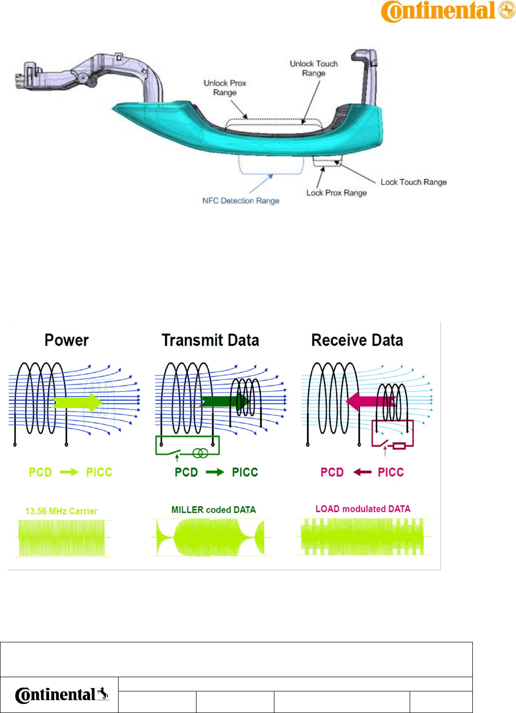
5 Detection area ........................................................................................................................ 22
5.1.1 Unlock Detection Area ............................................................................................... 22
5.1.2 Lock Detection Area .................................................................................................. 22
5.1.3 NFC Detection Area .................................................................................................. 22
6 Homologation setup ............................................................................................................... 24
6.1 General Test conditions ................................................................................................... 24
6.2 Material provided by Continental .................................................................................... 24
6.3 DHS detection tracking ..................................................................................................... 24
6.3.1 DHS connection instructions: .................................................................................... 25
6.3.2 Test box signals description: ..................................................................................... 28
6.3.3 Test box function: ...................................................................................................... 32
AuD5 NFC : product overview – usage for homologation
Date
Department
Designed by
Released by
Designation
IMS ID
161711
SAP ID
10 348616
Document version as of
April 27, 2017
Pages
5 of 33
Transmittal, reproduction, dissemination and/or editing of this document as well as utilization of its contents and communication thereof to others without express authorization are prohibited.
Offenders will be held liable for payment of damages. All rights created by patent grant or registration of a utility model or design patent are reserved.
1 General
1.1 Contact
Function
Name
Email
Phone
Project Leader
Andreas Moser
Andreas.moser@continental-corporation.com
+33 5 61 19 80 81
System Engineer
Stéphan Baudru
Stephan.baudru@continental-corporation.com
+33 5 61 19 74 02
Electronic Engineer
Cyril Robin
Cyril.robin @continental-corporation.com
+33 5 61 19 53 41
Software Engineer
Simon Forster
Simon.forster@continental-corporation.com
+33 5 61 19 33 87
Mechanical Engineer
Paul Raison
paul.raisson@continental-corporation.com
+33 5 61 19 55 31
Quality Engineer
Cindy Bardalou
Cindy.bardalou@continental-corporation.com
+33 5 62 23 15 05
1.2 Glossary
D5/C8: Audi platforms names
DH: Door Handle (means Outside Door Handle)
DHS: Door Handle Sensor Module (Unlock and Lock capacitive sensors)
LF: Low Frequency (125kHz signal for communication from ECU to Keyfob)
RF: Radio-Frequency (433 MHz signal for communication from Keyfob to ECU)
ECU: Electronic Control Unit
BCM: Body Controller Module
BCM2: Audi ECU name
NFC : Near Field Communication
PCD : Proximity Coupling Device (the Reader)
PICC : Proximity Integrated Circuit Card (the Smartcard/the Smartphone)
SE: System Engineering
ME: Mechanical Engineering
EE: Electrical Engineering
HW: Hardware
SW: Software
HSI: Hardware Software Interface
ICT: In Circuit Tester
AuD5 NFC : product overview – usage for homologation
Date
Department
Designed by
Released by
Designation
IMS ID
161711
SAP ID
10 348616
Document version as of
April 27, 2017
Pages
6 of 33
Transmittal, reproduction, dissemination and/or editing of this document as well as utilization of its contents and communication thereof to others without express authorization are prohibited.
Offenders will be held liable for payment of damages. All rights created by patent grant or registration of a utility model or design patent are reserved.
EOL: End of Line (Tester)
RT: Room Temperature
DV: Design Validation
PV: Product Validation
EMC: Electro Magnetic Compatibility
FMTT: Flash Monitoring and Tuning Tool (Continental Development Tool)
FMDD: Continental Development Tool replacing the FMTT
DGL: Design GuideLines
1.3 Validity and Track Changes
Items or parameters values changed compared to previous revision are highlighted in yellow.
Items or parameters values to be defined or to be confirmed are highlighted in blue.
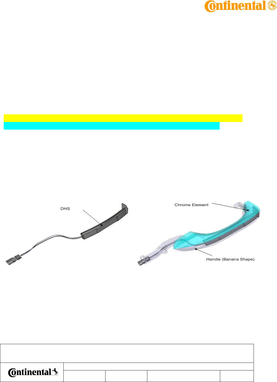
1.4 Type of Sensor
This sensor is a DHS.
The DHS is a standalone module with capacitive and NFC unctions.
This module is integrated into a DH, and used in Keyless Entry System, enabling 'key-free'
Vehicle Unlocking and Locking.
1.5 Sensor Functions
The DHS has 3 main functions :
- Unlock Function : Capacitive detection with 2 detection ranges.
- Lock Function : Capacitive detection with 2 detections ranges.
- NFC Function : Read/Write function of NFC Smartcards/Smartphones.
AuD5 NFC : product overview – usage for homologation
Date
Department
Designed by
Released by
Designation
IMS ID
161711
SAP ID
10 348616
Document version as of
April 27, 2017
Pages
7 of 33
Transmittal, reproduction, dissemination and/or editing of this document as well as utilization of its contents and communication thereof to others without express authorization are prohibited.
Offenders will be held liable for payment of damages. All rights created by patent grant or registration of a utility model or design patent are reserved.
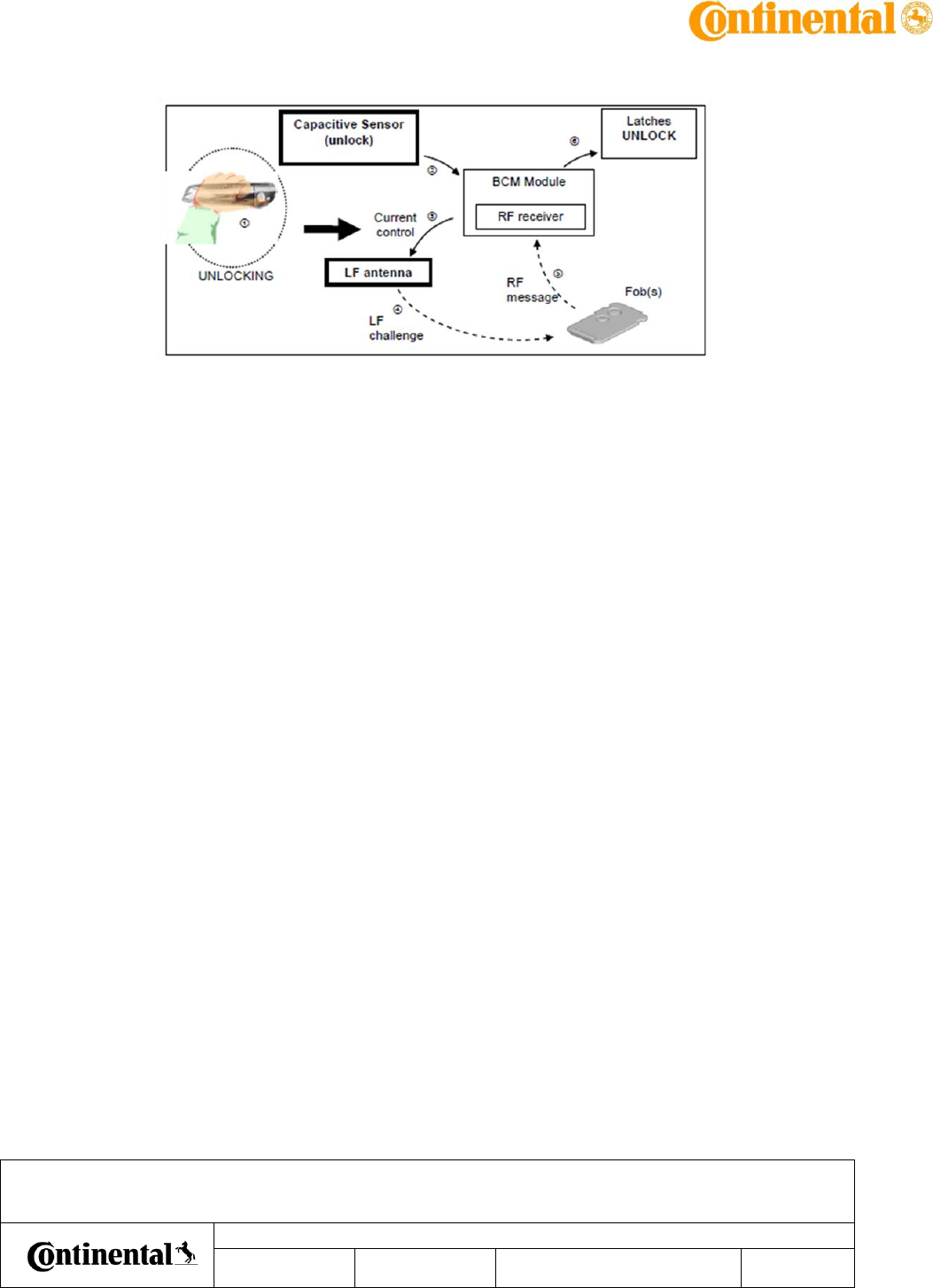
1.6 NFC Reader Principle
The NFC principle is based on electromagnetic coupling between 2 devices at close distance
(few cm).
The PCD emits a electromagnetic field on a 13.56 Mhz carrier. It will power the PICC via
Induction.
The PCD can transmit data via Miller Coding and receive data back via Load modulation.
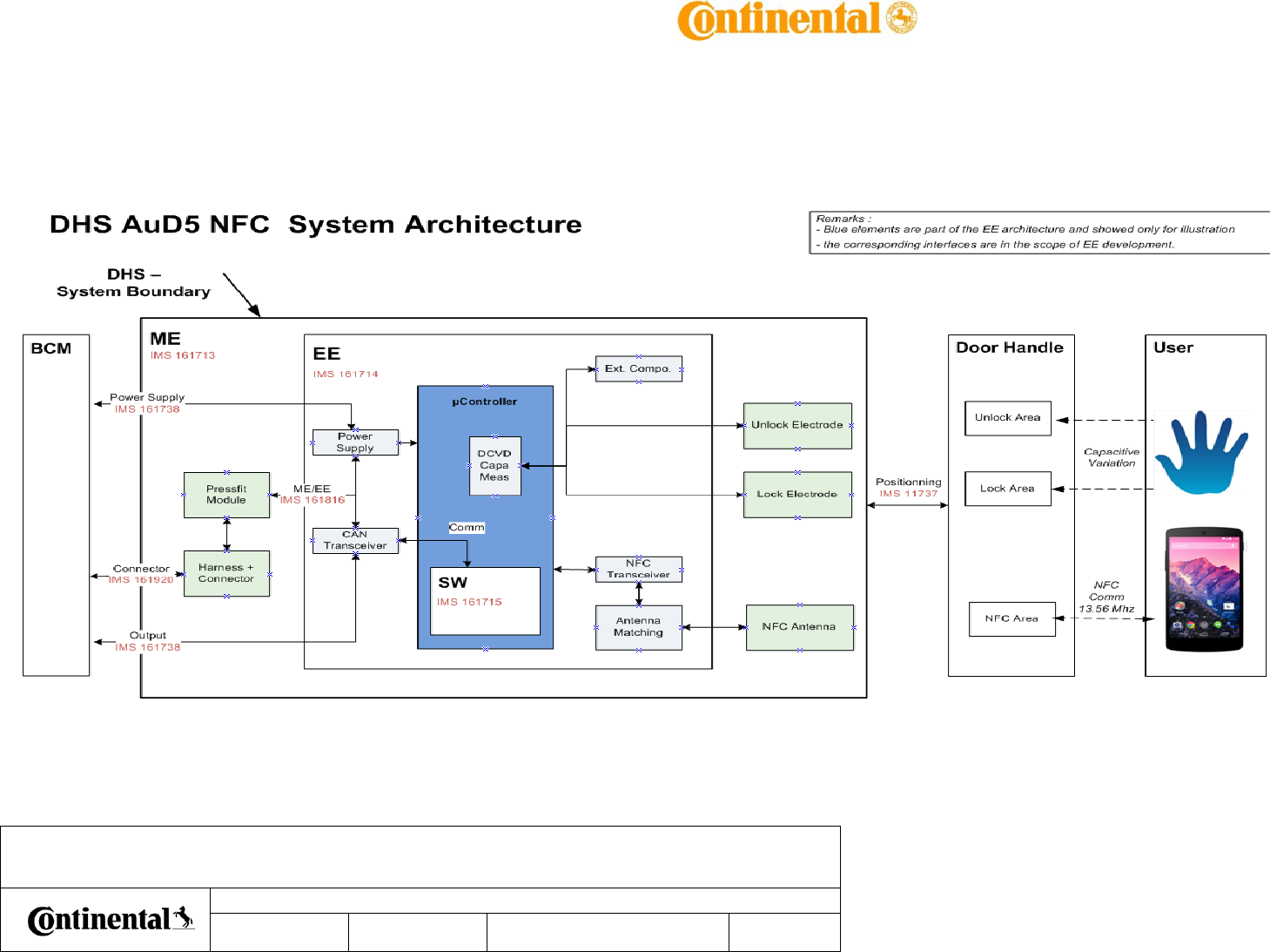
1.7 Example of sensor use
Example of Vehicle Access Process (Unlocking):
AuD5 NFC : product overview – usage for homologation
Date
Department
Designed by
Released by
Designation
IMS ID
161711
SAP ID
10 348616
Document version as of
April 27, 2017
Pages
8 of 33
Transmittal, reproduction, dissemination and/or editing of this document as well as utilization of its contents and communication thereof to others without express authorization are prohibited.
Offenders will be held liable for payment of damages. All rights created by patent grant or registration of a utility model or design patent are reserved.
As the user's hand approaches the capacitive sensor UNLOCK detection area, sensor
communicates detection to BCM Module. Then, the corresponding LF antenna on front side is
driven by system to send LF challenge to fob(s) to perform the user's identification process.
The same principle is used to Lock the vehicle, with a capacitive sensor LOCK detection area.
The NFC device tap is used to toggle the vehicle locking status.
2 System Architecture
2.1 Alternative System Architectures
Major evaluation criteria for architecture solutions was robustness, proven in use and cost.
Therefore the generic system architecture for Capa/NFC sensors proven in use in the generic
project was chosen.
2.2 Dynamic Behaviors
Dynamic behaviors, i.e. how the systems elements interact with each other dynamically, are
mainly driven by the SW.
Then, the timings and sequence charts are described in EE/SW Interface (HSI, IMS 161922) and
SW Requirements (IMS 161715)
AuD5 NFC : product overview – usage for homologation
Date
Department
Designed by
Released by
Designation
IMS ID
161711
SAP ID
10 348616
Document version as of
April 27, 2017
Pages
9 of 33
Transmittal, reproduction, dissemination and/or editing of this document as well as utilization of its contents and communication thereof to others without express authorization are prohibited.
Offenders will be held liable for payment of damages. All rights created by patent grant or registration of a utility model or design patent are reserved.
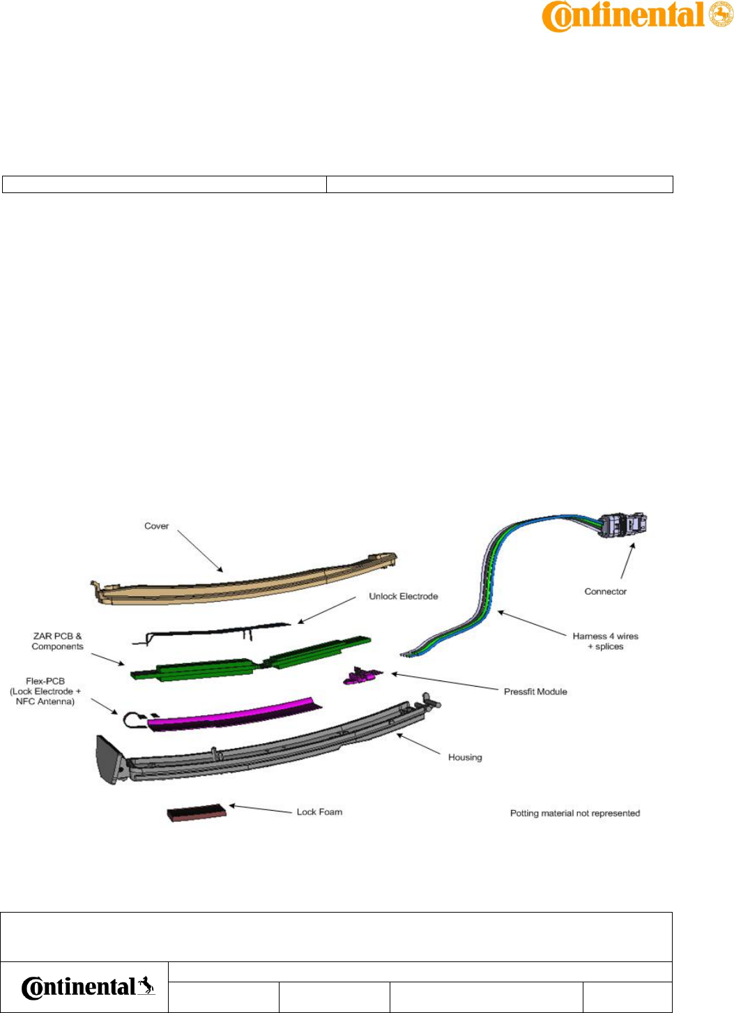
2.3 System Architecture
AuD5 NFC : product overview – usage for homologation
Date
Department
Designed by
Released by
Designation
IMS ID
161711
SAP ID
10 348616
Document version as of
April 27, 2017
Pages
10 of 33
Transmittal, reproduction, dissemination and/or editing of this document as well as utilization of its contents and communication thereof to others without express authorization are prohibited.
Offenders will be held liable for payment of damages. All rights created by patent grant or registration of a utility model or design patent are reserved.
2.4 Components
ID: 161948
State: Released
The DHS module shall be composed of:
- a packaging:
- plastic housing
- plastic cover
- potting material
- foam pad on Lock Area (the function is to keep the water out of the zone)
- a connection module:
- pressfit module
- harness + splices
- connector
- an electronic detection module:
- PCB with electronic circuit (for detection technology)
- Unlock Electrode (sensitive element) metal-stamping soldered on the PCB
- Lock Electrode (sensitive element) and NFC antenna on Flex-PCB soldered on the PCB
!
AuD5 NFC : product overview – usage for homologation
Date
Department
Designed by
Released by
Designation
IMS ID
161711
SAP ID
10 348616
Document version as of
April 27, 2017
Pages
11 of 33
Transmittal, reproduction, dissemination and/or editing of this document as well as utilization of its contents and communication thereof to others without express authorization are prohibited.
Offenders will be held liable for payment of damages. All rights created by patent grant or registration of a utility model or design patent are reserved.
2.5 Materials
2.5.1.1 Storage Temperature Range
ID: 161950
State: Released
The Mechanical Design shall guarantee the sensor robustness over Temperature storage range:
-40°C to +90°C.
2.5.1.2 Operating Temperature Range
ID: 161951
State: Released
The Mechanical Design shall guarantee the sensor robustness over Temperature operating
range: -40°C to +70°C.
2.5.2 Assembly / Sealing
2.5.2.1 Module Sealing
ID: 161954
State: Released
The DHS shall be sealed with PolyUrethane (PU) resin.
The sealing process shall ensure absolute water tightness.
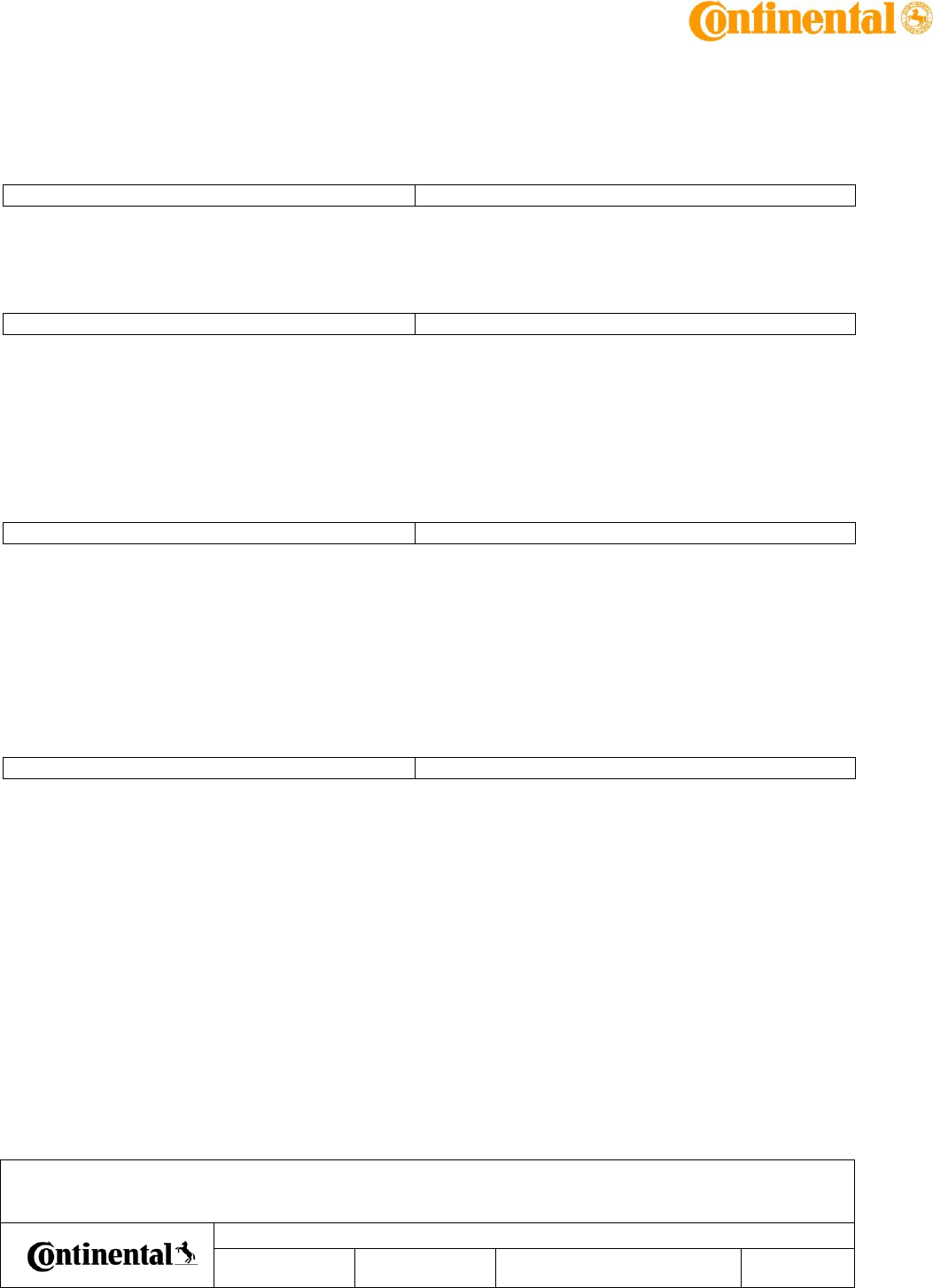
2.6 Connector requirements
2.6.1 Connector Reference
ID: 161919
State: Released
The connector is a directed part from Audi.
Connector Designation: Tyco MCON 4 ways, Coding B color white
Audi Reference: 4N0.973.704.A
AuD5 NFC : product overview – usage for homologation
Date
Department
Designed by
Released by
Designation
IMS ID
161711
SAP ID
10 348616
Document version as of
April 27, 2017
Pages
12 of 33
Transmittal, reproduction, dissemination and/or editing of this document as well as utilization of its contents and communication thereof to others without express authorization are prohibited.
Offenders will be held liable for payment of damages. All rights created by patent grant or registration of a utility model or design patent are reserved.
The coding and pinout shall be identical for all variants (Left/Right).
The pin coating shall be silver (Ag)
2.6.2 Connector Pinout
ID: 161920
State: Released
Pin number
Pin Name
Wire Color
Signal Description
A1
Vbatt
Grey
Kl30 - Power Supply
A2
Gnd
Black
Kl31 - Electrical Ground
A3
CAN-H
Blue
CAN -High
A4
CAN-L
Green
CAN -Low
AuD5 NFC : product overview – usage for homologation
Date
Department
Designed by
Released by
Designation
IMS ID
161711
SAP ID
10 348616
Document version as of
April 27, 2017
Pages
13 of 33
Transmittal, reproduction, dissemination and/or editing of this document as well as utilization of its contents and communication thereof to others without express authorization are prohibited.
Offenders will be held liable for payment of damages. All rights created by patent grant or registration of a utility model or design patent are reserved.
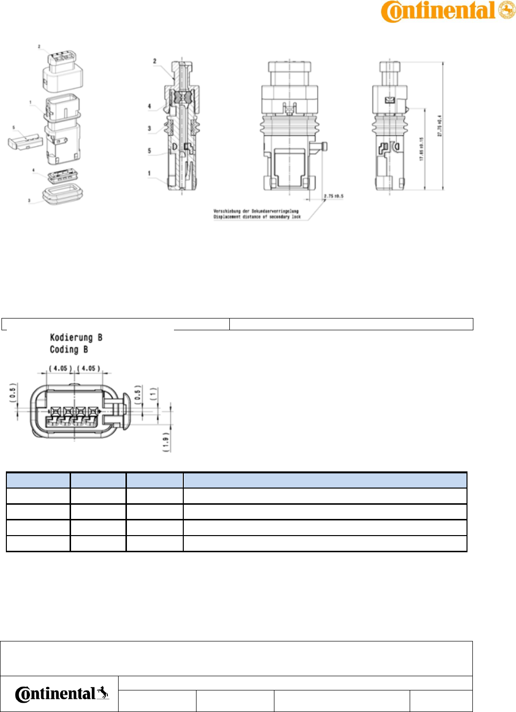
2.7 Variants
2.7.1 Right/Left Variants
ID: 161823
State: Released
There shall be 2 mechanicals variants:
1 for Right Handle.
1 for Left Handle.
These variants shall differ only by the:
- housing & cover shape
- Flex-PCB shape
Left sensor:
Right sensor:
AuD5 NFC : product overview – usage for homologation
Date
Department
Designed by
Released by
Designation
IMS ID
161711
SAP ID
10 348616
Document version as of
April 27, 2017
Pages
14 of 33
Transmittal, reproduction, dissemination and/or editing of this document as well as utilization of its contents and communication thereof to others without express authorization are prohibited.
Offenders will be held liable for payment of damages. All rights created by patent grant or registration of a utility model or design patent are reserved.
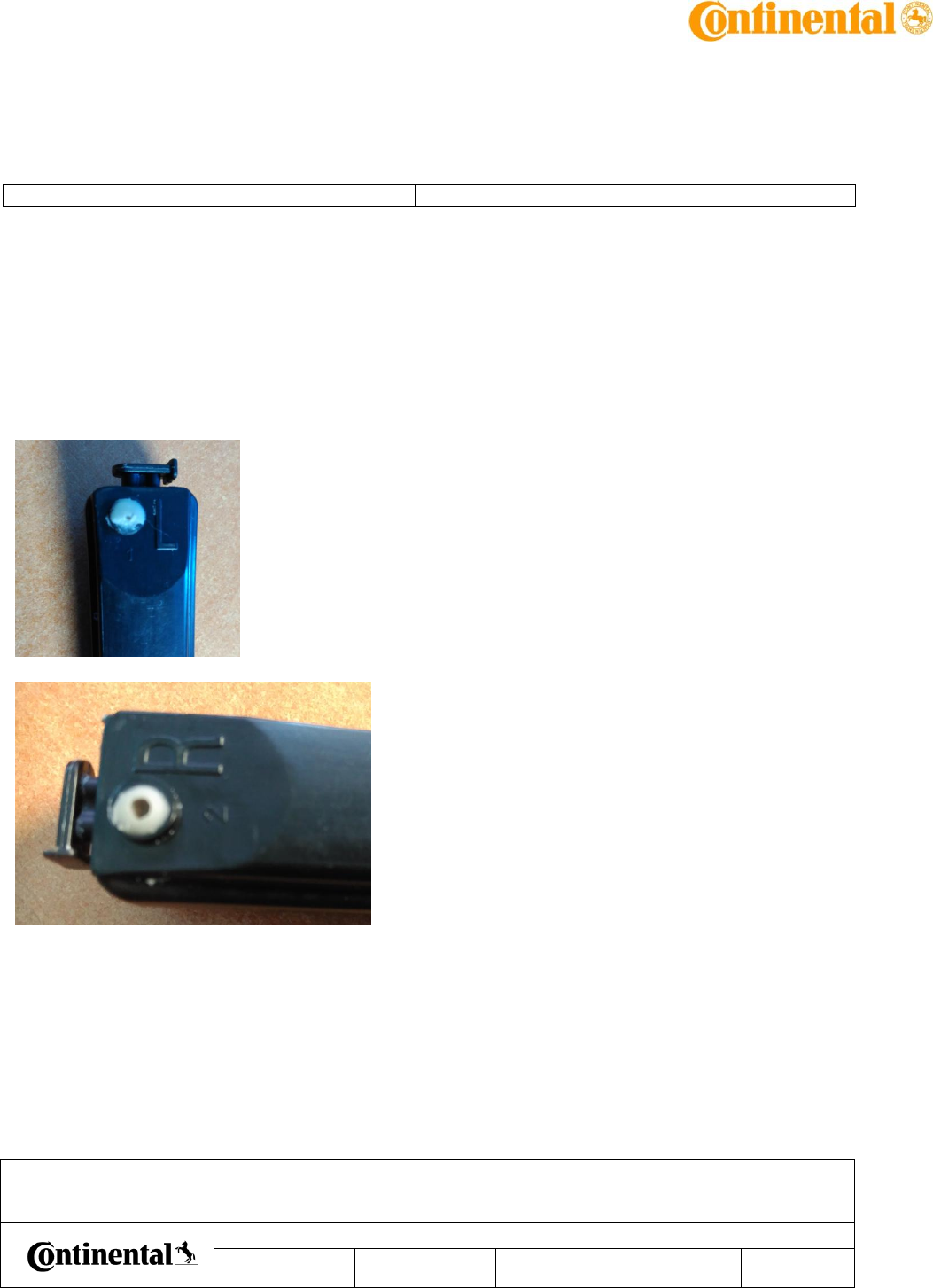
2.8 Electronics Structure and Interface
2.8.1 Electronics Block Diagram
ID: 161781
State: Released
The Electronics shall be compliant with the following Block Diagram.
2.8.2 Operating Temperature Range
ID: 161782
State: Released
The Electronic Design shall guaranty all electrical parameters over operating Temperature range
-40°C to +70°C, unless otherwise stated.
2.8.3 Operating Voltage Range
ID: 189713
State: Released
The Electronic Design shall guaranty all electrical parameters over operating Voltage range UDH
= 8V to 16V, unless otherwise stated.
2.8.4 Peak Power Consumption
ID: 161784
State: Released
The Electronic Design shall guarantee the following peak power consumption:
Parameter
Description
Min
Typ
Max
U.
Comments
IqpkOFF
Peak Quiescent Current
300
400
mA
µController Awake,
NFC polling
AuD5 NFC : product overview – usage for homologation
Date
Department
Designed by
Released by
Designation
IMS ID
161711
SAP ID
10 348616
Document version as of
April 27, 2017
Pages
15 of 33
Transmittal, reproduction, dissemination and/or editing of this document as well as utilization of its contents and communication thereof to others without express authorization are prohibited.
Offenders will be held liable for payment of damages. All rights created by patent grant or registration of a utility model or design patent are reserved.
CAN On
AuD5 NFC : product overview – usage for homologation
Date
Department
Designed by
Released by
Designation
IMS ID
161711
SAP ID
10 348616
Document version as of
April 27, 2017
Pages
16 of 33
Transmittal, reproduction, dissemination and/or editing of this document as well as utilization of its contents and communication thereof to others without express authorization are prohibited.
Offenders will be held liable for payment of damages. All rights created by patent grant or registration of a utility model or design patent are reserved.
2.8.5 Sleep Power Consumption
ID: 161785
State: Released
The Electronic Design shall guarantee the following power consumption in Sleep Mode:
Parameter
Description
Min
Typ
Max
U.
Comments
Iq_low
Quiescent Current in Sleep
Mode
67
µA
µController in Sleep
Mode,
No NFC polling
No Capacitive
Measurement
CAN in Sleep Mode
2.8.6 Current Consumption
ID: 161866
State: Released
Parameter
Description
Min
Typ
Max
U.
Comments
IqOFF
Average Dark current
200
TBC
300
500
TBC
µA
Unlock Capacitive
Polling @ 20 ms
Lock Capacitive
Polling @ 70 ms
NFC Polling @ 100 ms
2.8.7 CAN Voltage Range
ID: 161783
State: Released
The Electronic Design shall guaranty the CAN functionality (communication possible) over
operating Voltage range UDH = 6V to 18V.
In case voltage exceed 18V, CAN shall not be operational more than 1 minute.
In case voltage exceed 26V, CAN shall stop immediatly the CAN communication.
Overvoltage and undervoltage are manged by self check algorithm. Thresholds have tolerances
up to 27.5V.
See Requirement 171350

AuD5 NFC : product overview – usage for homologation
Date
Department
Designed by
Released by
Designation
IMS ID
161711
SAP ID
10 348616
Document version as of
April 27, 2017
Pages
17 of 33
Transmittal, reproduction, dissemination and/or editing of this document as well as utilization of its contents and communication thereof to others without express authorization are prohibited.
Offenders will be held liable for payment of damages. All rights created by patent grant or registration of a utility model or design patent are reserved.
3 Misuse Protections
After 20 lock/unlock activations in less than 10 seconds the sensor deactivates capa functions
for 30s.
After 20 NFC activations with wrong TAG in less than 10 seconds the sensor deactivates NFC
function for 30s.
AuD5 NFC : product overview – usage for homologation
Date
Department
Designed by
Released by
Designation
IMS ID
161711
SAP ID
10 348616
Document version as of
April 27, 2017
Pages
18 of 33
Transmittal, reproduction, dissemination and/or editing of this document as well as utilization of its contents and communication thereof to others without express authorization are prohibited.
Offenders will be held liable for payment of damages. All rights created by patent grant or registration of a utility model or design patent are reserved.
4 Communication
The DHS communicates detections ( lock/unlock/NFC) and status ( diagnosis) on CAN
4.1 CAN Communication Protocol
ID: 161957
State: Released
The DHS shall communicate with the BCM over a CAN High Speed network (500 kbits/s)
4.1.1 Lock Detection Message
ID: 162063
State: Released
If the DHS is in DETECTION or END_OF_DETECTION state on Lock, it shall set the following data
on the CAN Output :
If the DHS is in Prox range:
Frame NFC_TGS_01 : KY_Schliessen_Annaeherung = 0x1
If the DHS is in Touch range:
Frame NFC_TGS_01 : KY_Schliessen_Beteatigung = 0x1
Otherwise, these signals shall be set to 0x0.
4.1.2 Unlock Detection Messages
ID: 162061
State: Released
If the DHS is in DETECTION or END_OF_DETECTION state on Unlock, it shall set the following
data on the CAN Output :
If the DHS is in Prox range:
Frame NFC_TGS_01 : KY_Oeffnen_Annaeherung = 0x1
If the DHS is in Touch range:
Frame NFC_TGS_01 : KY_Oeffnen_Beteatigung =0x1
Otherwise, these signals shall be set to 0x0.

AuD5 NFC : product overview – usage for homologation
Date
Department
Designed by
Released by
Designation
IMS ID
161711
SAP ID
10 348616
Document version as of
April 27, 2017
Pages
19 of 33
Transmittal, reproduction, dissemination and/or editing of this document as well as utilization of its contents and communication thereof to others without express authorization are prohibited.
Offenders will be held liable for payment of damages. All rights created by patent grant or registration of a utility model or design patent are reserved.
4.1.3 DHS Error Message
ID: 167002
State: Released
If the DHS has detected any error, it shall pre-set the following data on the CAN Output.
The Frame NFC_TGS_01 is sent when an active condition is set (AC) or wake up condition (WUC)
is detected (if NM_NFC_TGS_NM_Activ_KL_15 (AC) set to 1 on or
NM_NFC_TGS_NM_Activ_Diagnose (AC) set to 1 or NM_NFC_TGS_NM_activ_Auth (AC & WUC)
set to 1 or NM_BCM2_Car_WakeUp (WUC) set to 1).
Frame NFC_TGS_01 : NFC_TGS_Fehler = 0x0 - No error
Frame NFC_TGS_01 : NFC_TGS_Fehler = 0x1 - DHS Internal error
Frame NFC_TGS_01 : NFC_TGS_Fehler = 0x2 - Antenna error
Frame NFC_TGS_01 : NFC_TGS_Fehler = 0x4 - Undervoltage
Frame NFC_TGS_01 : NFC_TGS_Fehler = 0x8 - Overvoltage
Frame NFC_TGS_01 : NFC_TGS_Fehler = 0x16 - Overheating
AuD5 NFC : product overview – usage for homologation
Date
Department
Designed by
Released by
Designation
IMS ID
161711
SAP ID
10 348616
Document version as of
April 27, 2017
Pages
20 of 33
Transmittal, reproduction, dissemination and/or editing of this document as well as utilization of its contents and communication thereof to others without express authorization are prohibited.
Offenders will be held liable for payment of damages. All rights created by patent grant or registration of a utility model or design patent are reserved.
4.3 NFC Communication
4.3.1 NFC type
ID: 167097
State: Released
The interface to smartphone / smartcard is defined according to ISO 14443A.
Once a PICC has been detected, the DHS shall enter the NFC RF discovery mode.
The DHS shall search for all allowed devices, and communicate with PICC type : NFC A Type 4.
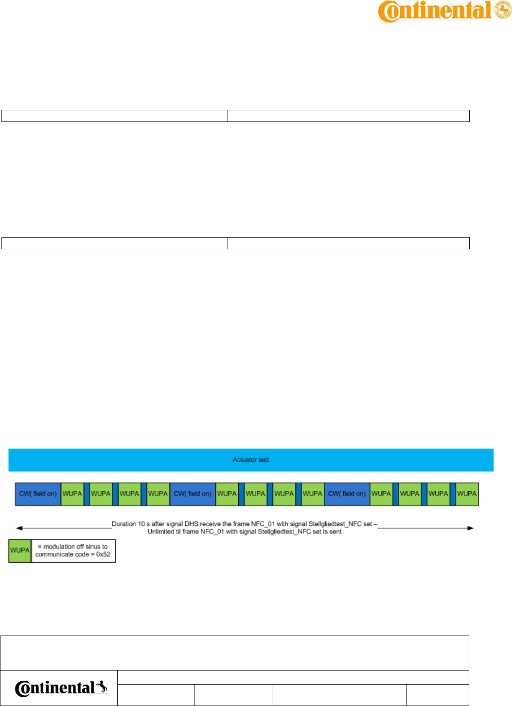
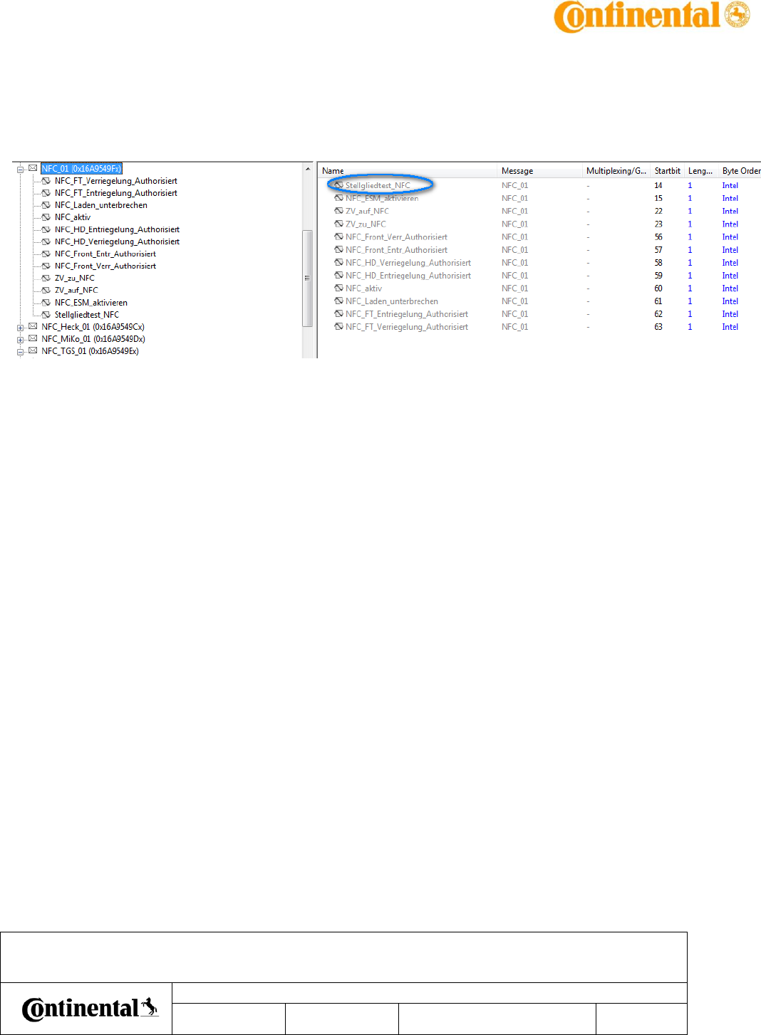
4.3.2 Actuator test
ID: 191483
State: Released
When DHS receive the frame NFC_01 with signal Stellgliedtest_NFC set, the DHS shall perform
the actuator test requirement as described below :
1. It shall turn on the antenna for at least p_t_tgs_actuator_test s and look for an external
device with RF discovery polling rate as short as possible
2. If it finds an appropriate counterpart (NFC-A Type 4), it shall activate and send the SELECT
command.
3. It shall feedback the result by changing the parameter "authenticated NFC-counterpart"
The DHS Application shall execute the acutator test (when requested) at any time regardless of
the Misuse or K15 State and ESM.
It is required that the field is turned on during the complete duration of the actuator test.
REQA is replaced by WUPA to ensure several communication possible whereas field is kept on.
The DHS shall stop the actuator test if:
AuD5 NFC : product overview – usage for homologation
Date
Department
Designed by
Released by
Designation
IMS ID
161711
SAP ID
10 348616
Document version as of
April 27, 2017
Pages
21 of 33
Transmittal, reproduction, dissemination and/or editing of this document as well as utilization of its contents and communication thereof to others without express authorization are prohibited.
Offenders will be held liable for payment of damages. All rights created by patent grant or registration of a utility model or design patent are reserved.
- receives the signal Stellgliedtest_NFC = 0 before the expiration of the timeout
p_t_tgs_actuator_test
- the timeout of p_t_tgs_actuator_test s expires
AuD5 NFC : product overview – usage for homologation
Date
Department
Designed by
Released by
Designation
IMS ID
161711
SAP ID
10 348616
Document version as of
April 27, 2017
Pages
22 of 33
Transmittal, reproduction, dissemination and/or editing of this document as well as utilization of its contents and communication thereof to others without express authorization are prohibited.
Offenders will be held liable for payment of damages. All rights created by patent grant or registration of a utility model or design patent are reserved.
5 Detection area
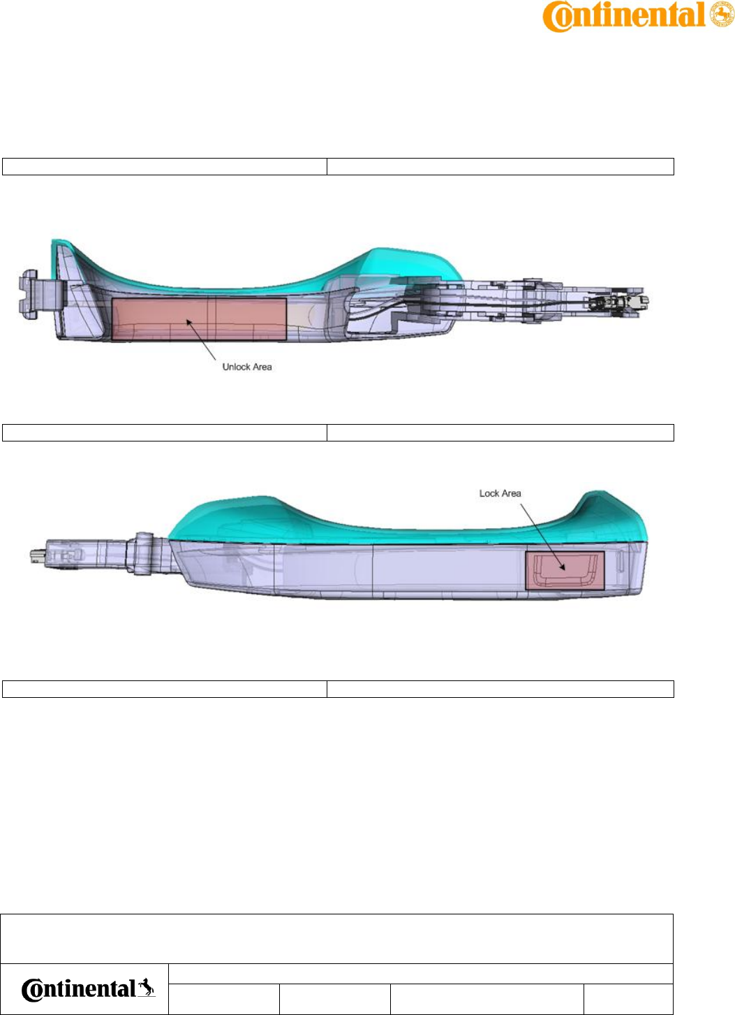
5.1.1 Unlock Detection Area
ID: 161859
State: Released
The Unlock detection area shall be limited to the designated area :
5.1.2 Lock Detection Area
ID: 161860
State: Released
The Lock detection area shall be limited to the designated area :
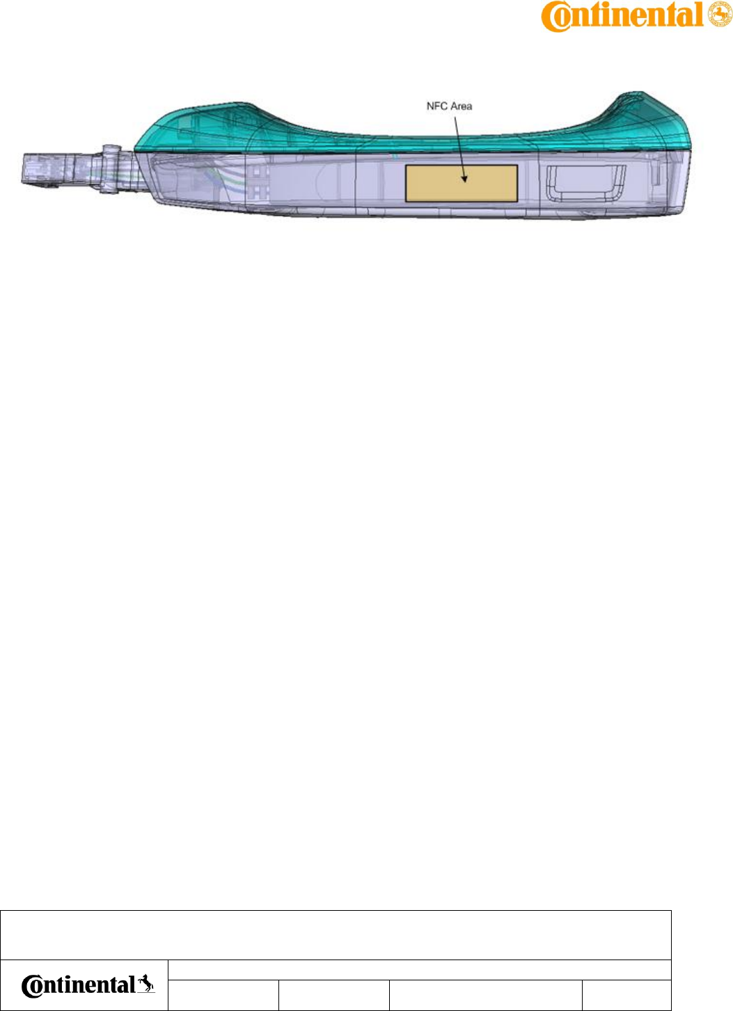
5.1.3 NFC Detection Area
ID: 166779
State: Released
The NFC detection area shall be limited to the designated area :
AuD5 NFC : product overview – usage for homologation
Date
Department
Designed by
Released by
Designation
IMS ID
161711
SAP ID
10 348616
Document version as of
April 27, 2017
Pages
23 of 33
Transmittal, reproduction, dissemination and/or editing of this document as well as utilization of its contents and communication thereof to others without express authorization are prohibited.
Offenders will be held liable for payment of damages. All rights created by patent grant or registration of a utility model or design patent are reserved.

AuD5 NFC : product overview – usage for homologation
Date
Department
Designed by
Released by
Designation
IMS ID
161711
SAP ID
10 348616
Document version as of
April 27, 2017
Pages
24 of 33
Transmittal, reproduction, dissemination and/or editing of this document as well as utilization of its contents and communication thereof to others without express authorization are prohibited.
Offenders will be held liable for payment of damages. All rights created by patent grant or registration of a utility model or design patent are reserved.
6 Homologation setup
6.1 General Test conditions
General test conditions valid for all tests :
- All materials within 100mm around the door handle sensor during the test process
(includes Handle fixations - “Sensor fixture” / “Holder”, sockets, base plate, … -,
actuation system –robot, arms, …-, tester mechanics, …) shall be made of non conductive
material and as electrostatic neutral as possible (ie PEEK or PA66 GF30) in order to avoid
influence on detection distance.
- Conductive environment (Robot, arms, jig walls, etc …) shall be at least 100mm away
from Door Handle Assembly throughout the test sequence (except for Targets
themselves).
- The connector positions, and then the bed-of-nails, shall be 100 mm away from the
sensitive areas during the test.
- The DHS shall have its dedicated power supply. This power supply shall be a low noise
linear power supply (switch mode power supplies are prohibited)
- No noise shall be visible by oscilloscope on DHS supply line.
6.2 Material provided by Continental
- 5 DHS Left number 84, 30,67,26,34
- 5 DHS right number 42, 13,9,15,48
- Test box with usage described below
- Wires / connector
- Tag for NFC detection
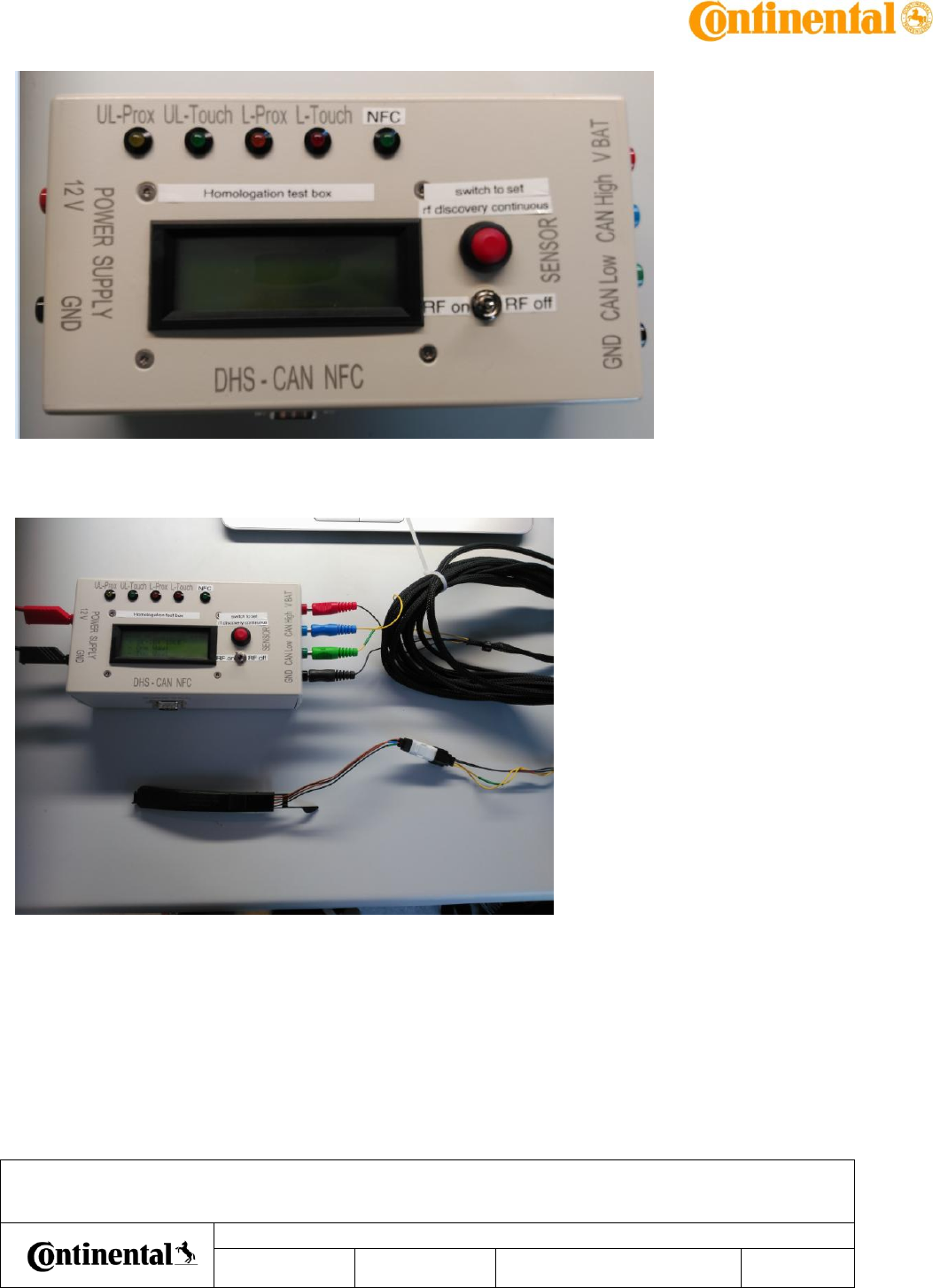
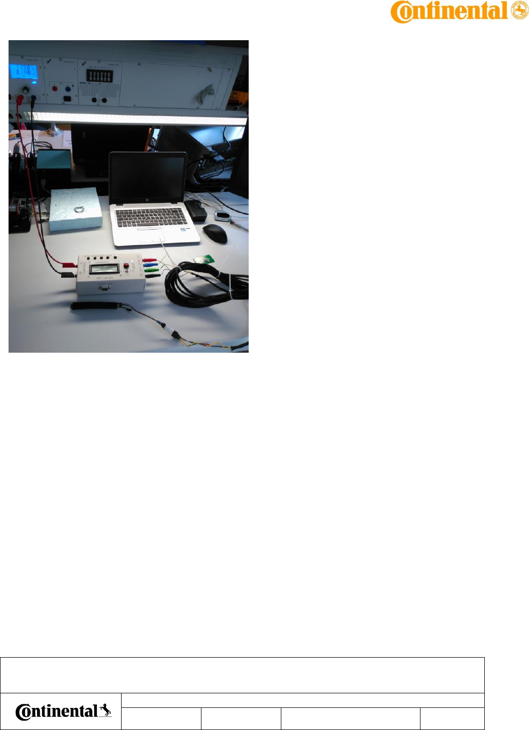
6.3 DHS detection tracking
In order to check DHS signal during homologation tests, a specific test box is provided by
Continental.
AuD5 NFC : product overview – usage for homologation
Date
Department
Designed by
Released by
Designation
IMS ID
161711
SAP ID
10 348616
Document version as of
April 27, 2017
Pages
25 of 33
Transmittal, reproduction, dissemination and/or editing of this document as well as utilization of its contents and communication thereof to others without express authorization are prohibited.
Offenders will be held liable for payment of damages. All rights created by patent grant or registration of a utility model or design patent are reserved.
6.3.1 DHS connection instructions:
Global overview when sensor is plugged to testbox:
AuD5 NFC : product overview – usage for homologation
Date
Department
Designed by
Released by
Designation
IMS ID
161711
SAP ID
10 348616
Document version as of
April 27, 2017
Pages
26 of 33
Transmittal, reproduction, dissemination and/or editing of this document as well as utilization of its contents and communication thereof to others without express authorization are prohibited.
Offenders will be held liable for payment of damages. All rights created by patent grant or registration of a utility model or design patent are reserved.
AuD5 NFC : product overview – usage for homologation
Date
Department
Designed by
Released by
Designation
IMS ID
161711
SAP ID
10 348616
Document version as of
April 27, 2017
Pages
27 of 33
Transmittal, reproduction, dissemination and/or editing of this document as well as utilization of its contents and communication thereof to others without express authorization are prohibited.
Offenders will be held liable for payment of damages. All rights created by patent grant or registration of a utility model or design patent are reserved.
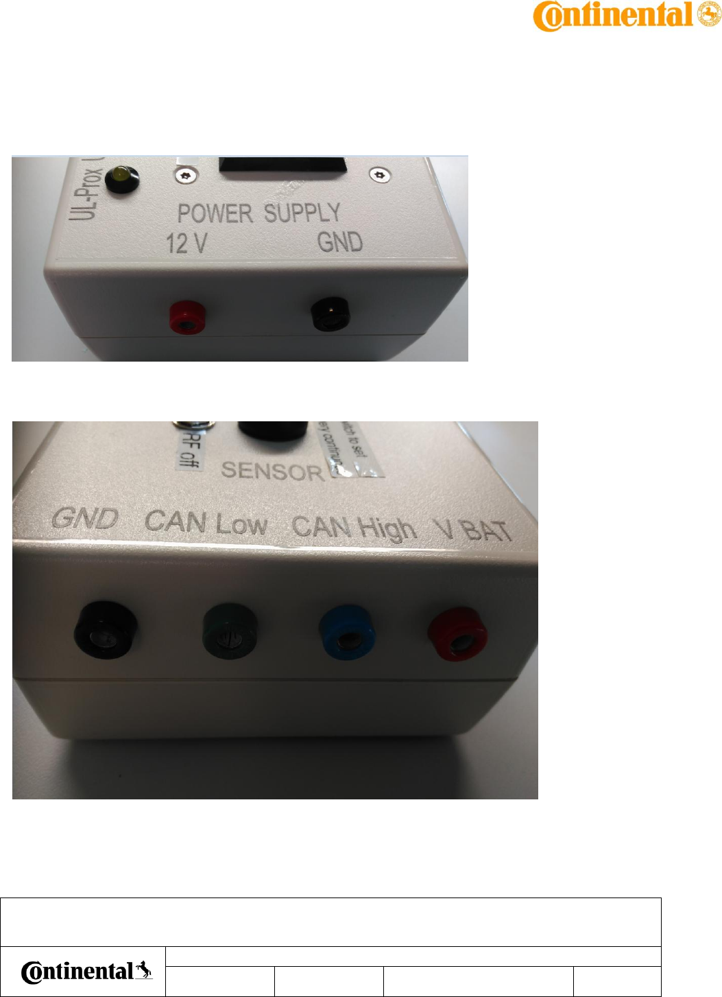
Supply test box with 12V.
Plug DHS Vbat and GND to corresponding Vbat and GND input on test box:
Plug DHS CAN low and Can High to corresponding CAN low and Can High input on test box with
color corresponding plugs:
AuD5 NFC : product overview – usage for homologation
Date
Department
Designed by
Released by
Designation
IMS ID
161711
SAP ID
10 348616
Document version as of
April 27, 2017
Pages
28 of 33
Transmittal, reproduction, dissemination and/or editing of this document as well as utilization of its contents and communication thereof to others without express authorization are prohibited.
Offenders will be held liable for payment of damages. All rights created by patent grant or registration of a utility model or design patent are reserved.
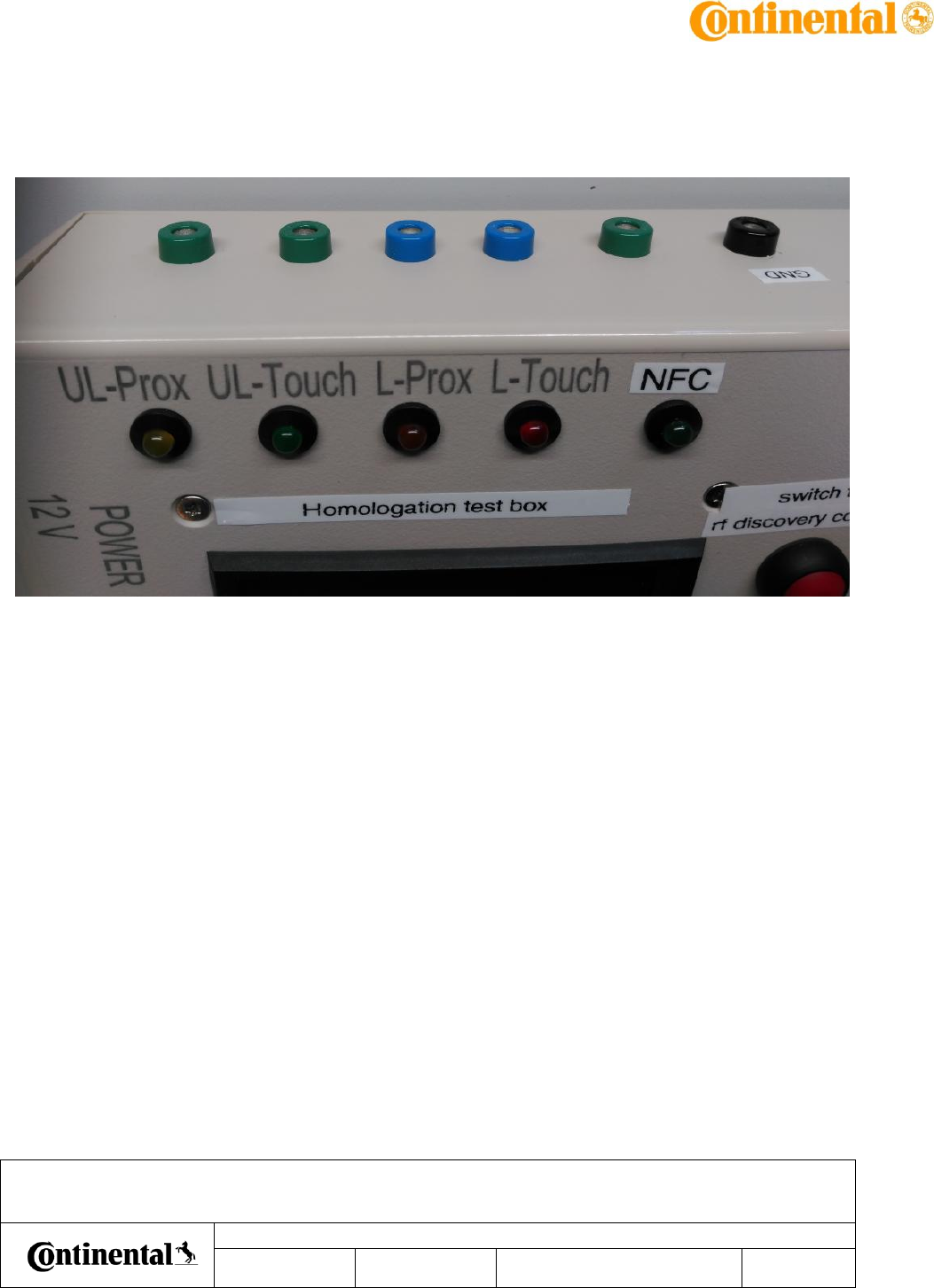
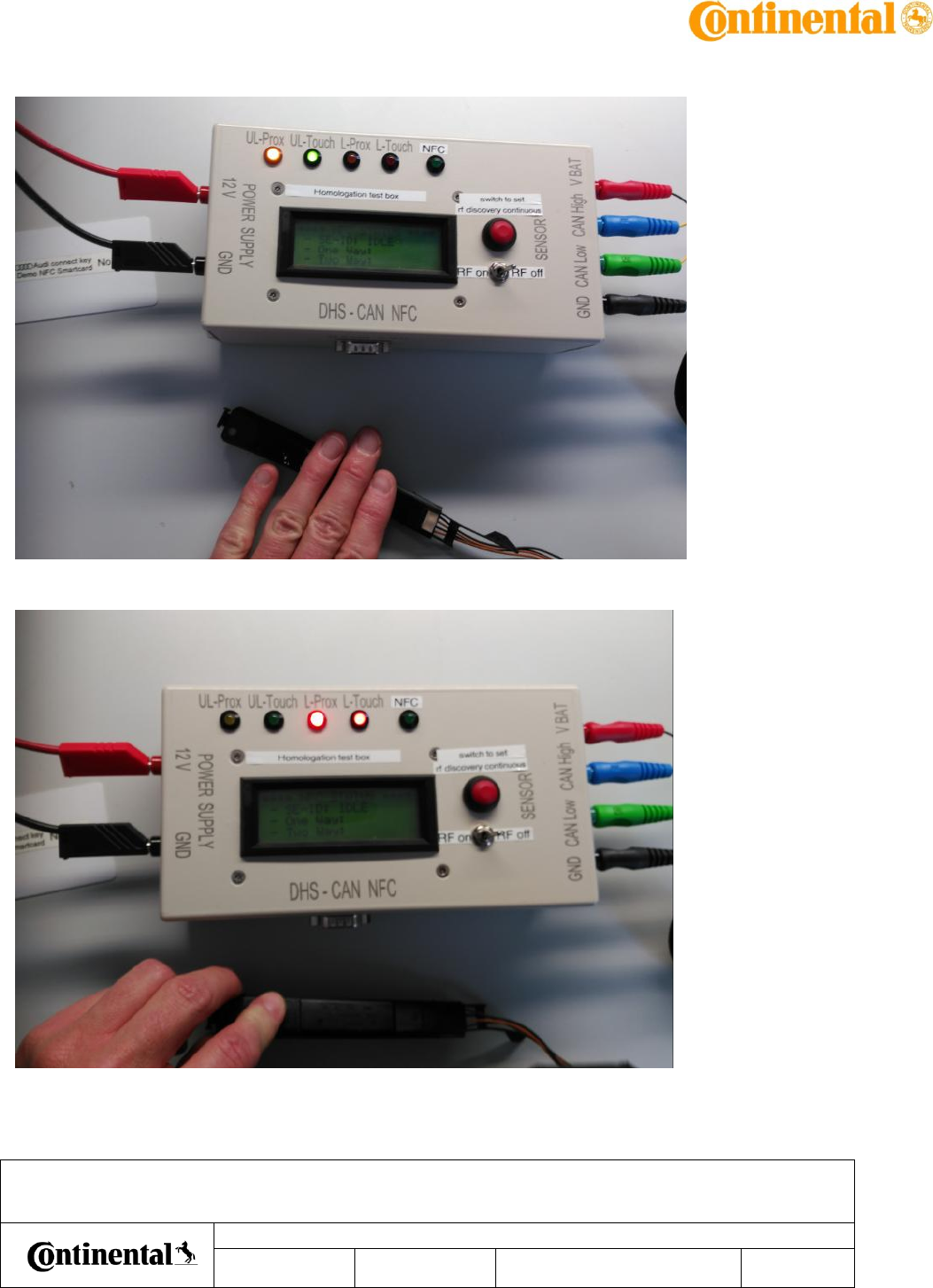
6.3.2 Test box signals description:
LEDs are available to check visually if sensor is working.
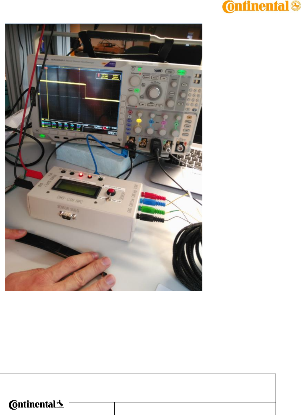
For each lead an output is available and can be connected directly to any recorder (
oscilloscope,…). High level means no detection, low level means detection.
Below example with lock touch : L_Touch output is plugged to oscilloscope – GND also :
AuD5 NFC : product overview – usage for homologation
Date
Department
Designed by
Released by
Designation
IMS ID
161711
SAP ID
10 348616
Document version as of
April 27, 2017
Pages
29 of 33
Transmittal, reproduction, dissemination and/or editing of this document as well as utilization of its contents and communication thereof to others without express authorization are prohibited.
Offenders will be held liable for payment of damages. All rights created by patent grant or registration of a utility model or design patent are reserved.
AuD5 NFC : product overview – usage for homologation
Date
Department
Designed by
Released by
Designation
IMS ID
161711
SAP ID
10 348616
Document version as of
April 27, 2017
Pages
30 of 33
Transmittal, reproduction, dissemination and/or editing of this document as well as utilization of its contents and communication thereof to others without express authorization are prohibited.
Offenders will be held liable for payment of damages. All rights created by patent grant or registration of a utility model or design patent are reserved.
Unlock prox/touchdetection : touch hand in unlock area :
Lock prox/touchdetection : touch hand in unlock area :
AuD5 NFC : product overview – usage for homologation
Date
Department
Designed by
Released by
Designation
IMS ID
161711
SAP ID
10 348616
Document version as of
April 27, 2017
Pages
31 of 33
Transmittal, reproduction, dissemination and/or editing of this document as well as utilization of its contents and communication thereof to others without express authorization are prohibited.
Offenders will be held liable for payment of damages. All rights created by patent grant or registration of a utility model or design patent are reserved.
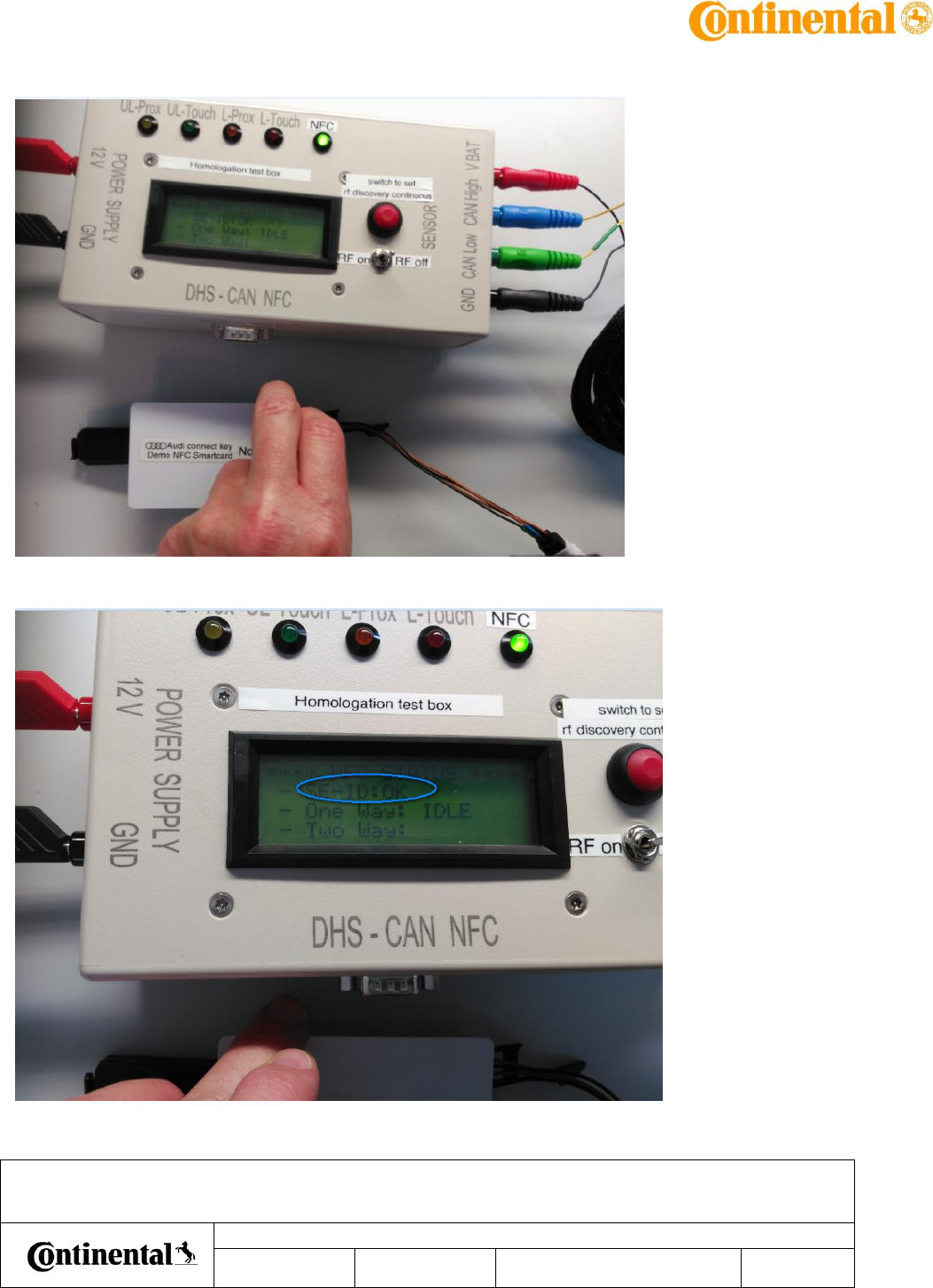
NFC detection : approach TAG against NFC area : message on test box = “SE-ID:OK”
AuD5 NFC : product overview – usage for homologation
Date
Department
Designed by
Released by
Designation
IMS ID
161711
SAP ID
10 348616
Document version as of
April 27, 2017
Pages
32 of 33
Transmittal, reproduction, dissemination and/or editing of this document as well as utilization of its contents and communication thereof to others without express authorization are prohibited.
Offenders will be held liable for payment of damages. All rights created by patent grant or registration of a utility model or design patent are reserved.
Before to start any test, check for each LED and corresponding output that sensor is working
fine:
- touch lock area with thumb for at least 300 ms => check lock prox and lock touch
function
- touch unlock area with hand for at least 200 ms => check unlock prox and unlock touch
function
- approach TAG against NFC area => check NFC function
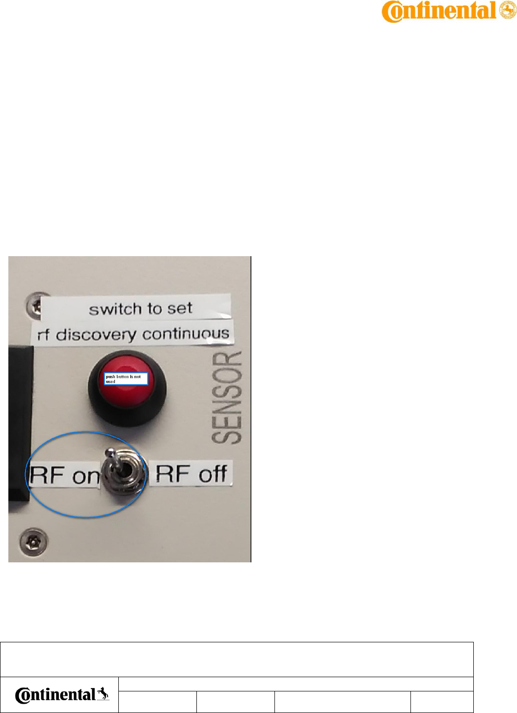
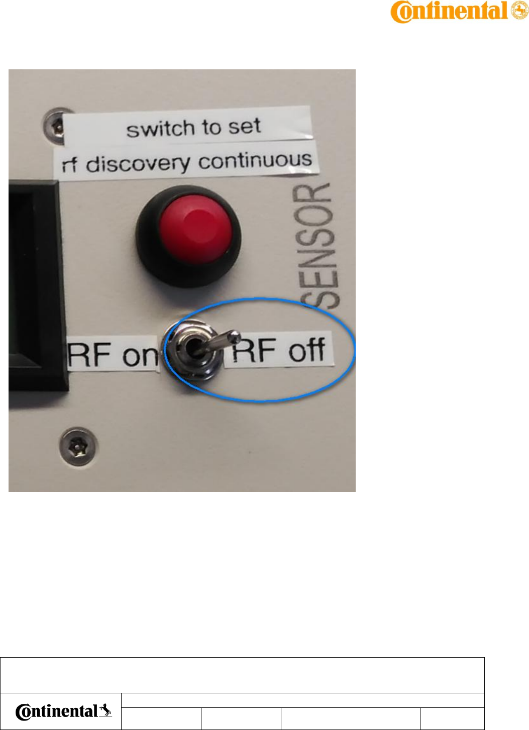
6.3.3 Test box function:
To set the sensor in “normal mode”, as it is in vehicle configuration without communication
with BCM, let the switch in position RF-OFF.
To set the sensor in “RF Discovery mode”, set the switch in position RF-ON. The sensor will send
continuous WUPA as described in chapter “actuator test”.
To check no loss of detection Tag provided by continental shall lay against the DHS in front of
NFC Area as describe in chapter”NFC detection area”.
AuD5 NFC : product overview – usage for homologation
Date
Department
Designed by
Released by
Designation
IMS ID
161711
SAP ID
10 348616
Document version as of
April 27, 2017
Pages
33 of 33
Transmittal, reproduction, dissemination and/or editing of this document as well as utilization of its contents and communication thereof to others without express authorization are prohibited.
Offenders will be held liable for payment of damages. All rights created by patent grant or registration of a utility model or design patent are reserved.
To exit the sensor from “RF Discovery mode”, set the switch in position RF-OFF. The sensor will
exit from this mode to normal mode in about 1s.
FCC Regulatory notices
Modification statement
Continental Automotive GmbH has not approved any changes or modifications to this device by the user. Any
changes or modifications could void the user’s authority to operate the equipment.
Interference statement
This device complies with Part 15 of the FCC Rules. Operation is subject to the following two conditions: (1)
this device may not cause interference, and (2) this device must accept any interference, including interference
that may cause undesired operation of the device.
Wireless notice
This device complies with FCC radiation exposure limits set forth for an uncontrolled environment and meets
the FCC radio frequency (RF) Exposure Guidelines. This transmitter must not be co-located or operating in
conjunction with any other antenna or transmitter.
FCC Class B digital device notice
This equipment has been tested and found to comply with the limits for a Class B digital device, pursuant to
part 15 of the FCC Rules. These limits are designed to provide reasonable protection against harmful
interference in a residential installation. This equipment generates, uses and can radiate radio frequency energy
and, if not installed and used in accordance with the instructions, may cause harmful interference to radio
communications. However, there is no guarantee that interference will not occur in a particular installation. If
this equipment does cause harmful interference to radio or television reception, which can be determined by
turning the equipment off and on, the user is encouraged to try to correct the interference by one or more of the
following measures:
- Reorient or relocate the receiving antenna.
- Increase the separation between the equipment and receiver.
- Connect the equipment into an outlet on a circuit different from that to which the receiver is connected.
- Consult the dealer or an experienced radio/TV technician for help.