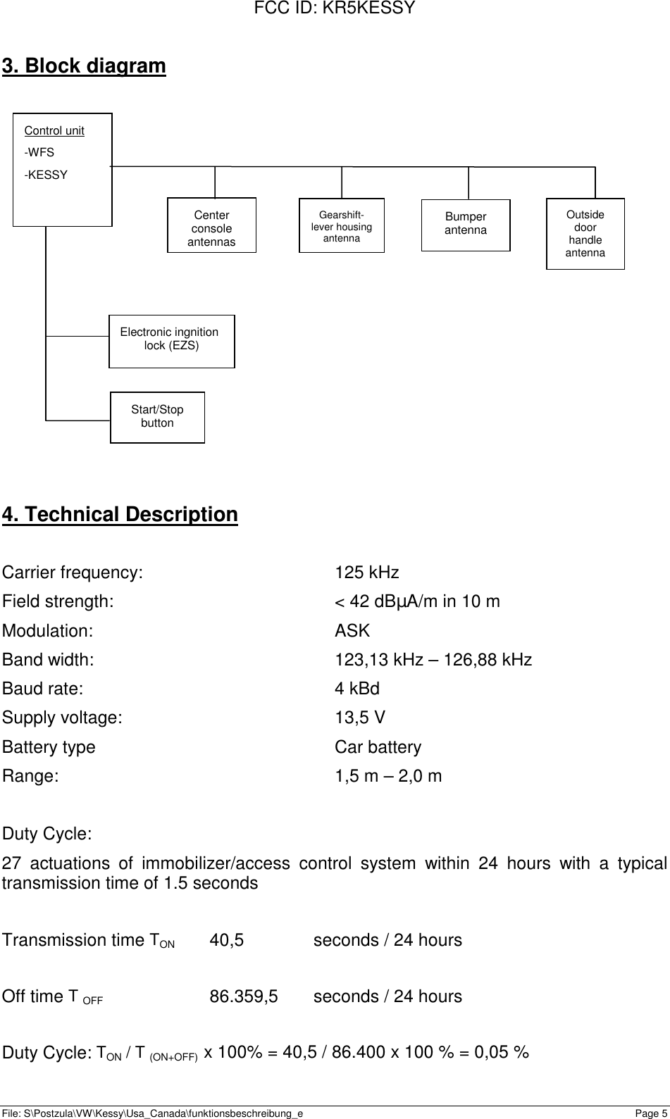
Continental Automotive KESSY Keyless access control system & imobilizer, KESSY User Manual

Continental Automotive GmbH Keyless access control system & imobilizer, KESSY

User manual

FCC ID: KR5KESSYFile: S\Postzula\VW\Kessy\Usa_Canada\funktionsbeschreibung_e Page 1Functional Description /User ManualforSIEMENSKeyless access control system andimmobilizerType KESSY
FCC ID: KR5KESSYFile: S\Postzula\VW\Kessy\Usa_Canada\funktionsbeschreibung_e Page 21.  Functional Description - Keyless access control system andimmobilizer, type KESSY1.1.  General functional descriptionThe keyless access control system, type Kessy, enables convenient utilization of thevehicle. To use the vehicle, the driver only needs to take the key along with him/her.The vehicle communicates with the system inductively via antennas. These antennasare located in the outside door handles, in the rear bumper, in the gearshift - leverhousing , in the center console, in the central rear arm rest and in the backlite shelf.These antennas are driven inductively with a frequency of 125 kHz. The system'srange is limited in a defined fashion by damping the body sheet metal. In the vehicleinterior, the ranges of the various antennas overlap, which enables location of thekey.1.2.  Keyless access control (maximum assembly variant M-Option)The handle of the driver's door and the boot lid are equipped with contacts to ensurethe locking and unlocking functions. If the door handle of a locked vehicle is pulled,the control unit activates the antennas on the vehicle's side where the handle hasbeen pulled. These antennas generate an inductive field of 125 kHz which enableidentification of the transponder located in the key. In case of successful evaluationby the KESSY control unit and with the outside door handle actuated, the command"Open door" is issued, i.e. the door opening assistant and the central locking systemare activated.If the "locking button" is pushed while the vehicle is unlocked, the identification proc-ess is started, i.e. the KESSY control unit starts a request for a valid key. The keyreturns a corresponding response to the KESSY control unit. If the key has been ac-tivated successfully by the KESSY control unit, the central locking system is activatedand the vehicle is locked.
FCC ID: KR5KESSYFile: S\Postzula\VW\Kessy\Usa_Canada\funktionsbeschreibung_e Page 31.3. Keyless start/stop (maximum assembly variant M-Option)The system provides the function which enables starting/stopping the engine withoutkey actuation.The prerequisite for starting the vehicle is a key allocated to the vehicle, which istaken along by the user and is clearly inside the vehicle. By actuating the starting de-vice, the driver starts the identification process, i.e. the KESSY control unit issues arequest for a valid key inside the vehicle. The key returns an appropriate response tothe KESSY control unit. In case of successful identification of the key, the vehicle isstarted and the immobilizer is deactivated.Prinzipdarstellung    Fig. 1indukt. Wirkungsbereich Türgriffantennenindukt. Wirkungsbereich Innenraumantennenindukt. Wirkungsbereich Hutablageantennneindukt. Wirkungsbereich Stoßfängerantenneinduktive AntennenFunksenderFunkempfänger im SteuergerätFunk WirkungsbereichBlock diagram Fig. 1-  inductive range of action ofoutside door handle antennas-  range of action of center console /rear arm rest antennas- inductive range of action of an-tenna in backlite shelf-  inductive range of action of   bumper antenna- inductive antennas- key- radio receiver in control unit- range of radio action
FCC ID: KR5KESSYFile: S\Postzula\VW\Kessy\Usa_Canada\funktionsbeschreibung_e Page 41.3.  Immobilizer  (reduced assembly variant Basic-Option)The immobilizer is deactivated on vehicle start: the key is identified by the integratedtransponder which communicates via inductive transmission with the electronic igni-tion lock (EZS). The EZS supplies the transponder with inductive energy. Themagnetic field is modulated with data which are sent to the electronic ignition lock bythe control unit. This data transfer operates at an operating frequency of 125 kHz.The response returned by the key is demodulated in the electronic ignition lock, andsent back to the control unit. If identification was successful, the immobilizer is dis-abled.EZSWFS-ControllerPCF7991ATWFS-AntenneSCLK DOUTDINTransp.2. List of variants5WK4 7026 Control unit – maximum assembly (M-Option)5WK4 7025 Control unit – reduced assembly (Basic-Option)only immobiliser function5WK4 5014 Center console antenna / rear arm rest antenna5WK4 5015 Gearshift-lever housing antenna5WK4 5016 Bumper antenna5WK4 5017 Backlite shelf antenna3D0 905 865 Electronic ignition lock (EZS) antenna3D0 837 205/206 Outside door handle antennaWFS-Antenne - immobilizerantenna
FCC ID: KR5KESSYFile: S\Postzula\VW\Kessy\Usa_Canada\funktionsbeschreibung_e Page 5Control unit-WFS-KESSY3. Block diagram4. Technical DescriptionCarrier frequency: 125 kHzField strength: < 42 dBµA/m in 10 mModulation: ASKBand width: 123,13 kHz – 126,88 kHzBaud rate: 4 kBdSupply voltage: 13,5 VBattery type Car batteryRange: 1,5 m – 2,0 mDuty Cycle:27 actuations of immobilizer/access control system within 24 hours with a typicaltransmission time of 1.5 secondsTransmission time TON 40,5 seconds / 24 hoursOff time T OFF 86.359,5 seconds / 24 hoursDuty Cycle: TON / T (ON+OFF)  x 100% = 40,5 / 86.400 x 100 % = 0,05 %Gearshift-lever housingantennaBumperantennaElectronic ingnitionlock (EZS)Start/StopbuttonCenterconsoleantennasOutsidedoorhandleantenna
FCC ID: KR5KESSYFile: S\Postzula\VW\Kessy\Usa_Canada\funktionsbeschreibung_e Page 6
FCC ID: KR5KESSYFile: S\Postzula\VW\Kessy\Usa_Canada\funktionsbeschreibung_e Page 75. Label DesignFCC Declaration:FCC ID: KR5KESSYThis device complies with part 15 of the FCC Rules. Operation is subject to the fol-lowing two conditions: (1) This device may not cause harmful interference, and (2)this device must accept interference received, including interference that may causeundesired operation.
FCC ID: KR5KESSYFile: S\Postzula\VW\Kessy\Usa_Canada\funktionsbeschreibung_e Page 86. Power up of test samples6.1. Test sample "Keyless access control system"The test setup consists of the following components:-  Control unit 5WK4 7026-  Test box "antenna change-over switch"-  Wiring harness "Test box – Control unit"-  Wiring harness "Test box – Antennas"-  Antennas: 1 Gearshift-lever housing antenna 5WK4 5015 (antenna 2.3)2 Center console/ rear arm rest antennas  5WK4 5014(antennas 2.1 and 2.2)1 backlite shelf antenna  5WK4 5017 (antenna 4)2 outside door handle antennas 3D0 837 205/206 (antennas 3.1 and 3.2)2 bumper antennas 5WK4 5016 (antennas 1.1 and 1.2)- 12V Car battery (not supplied)Design:Connect the control unit to the test box. Connect the test box to the antennas sup-plied with the system, taking careful account of the designations on wiring harnessand antennas. More precise allocation of connector– socket is not necessary, as allconnections are mechanical or color-coded.Turn master switch of test box "OFF".During climatic tests, the test box should definitely be located outside the climaticcabinet.The entire test set up is connected to power via the two banana jacks on the test box:Banana jack, red : +12VBanana jack, blue : GND (ground)The power consumption in case of operation amounts to max. 10A.
FCC ID: KR5KESSYFile: S\Postzula\VW\Kessy\Usa_Canada\funktionsbeschreibung_e Page 9Operation:The four-level rotary switch in the test box enables selection which antennas aredriven.The following combinations are possible:1.  Backlite shelf antennas (antenna group 1)2.  Interior antennas (antenna group 2)3.  Door handle antennas (antenna group 3)4.  Bumper antennas (antenna 4)Before changing over to a different antenna, the testing staff should change themaster switch on the test box to "OFF", and subsequently to "ON".Select the desired mode via the switch "modulation – no modulation". To change themode, turn the master switch to "OFF".In the "modulation" mode, a telegram modulated to the carrier frequency is emitted.The modulation-free carrier frequency is sent in the mode "no modulation".Turn the main switch on the test box to "ON". Thus, the selected antenna will transmit(telegrams with a duration of approx. 40ms at intervals of 500ms), until the switch isturned back to "OFF".This procedure does not correspond to the normal operating mode of the an-tenna drivers! This procedure is only used to simplify emission measurements.
FCC ID: KR5KESSYFile: S\Postzula\VW\Kessy\Usa_Canada\funktionsbeschreibung_e Page 106.2. Test sample "immobilizer"The test set-up consists of the following components:-  Control unit 5WK4 7025-  Electronic ignition lock (EZS) 3D0 905 865-  Wiring harness "Control unit – electronic ignition lock (EZS)"-  Wiring harness "EZS – power supply"-  12V car battery (is not supplied with the system)Design:"No modulation" mode: Connect the EZS to the power supply via a wiring harness"EZS – power supply"."Modulation" mode: Connect the control unit to the EZS and the power supply via thewiring harness "Control unit – electronic ignition lock (EZS)".Operation:After connection has been established, the immobilizer antenna emits in the selectedmode. In "no modulation" mode, the carrier frequency is sent permanently. If "modu-lation" has been selected, the system emits a modulated telegram at intervals of 1.6seconds.This procedure does not correspond to the normal operating mode of the im-mobilizer! This procedure is only used to simplify emission measurements.Should you encounter any problems or have any queries, please do not hesitate tocontact:SIEMENS Automotive AGAT BE AS CS5Mr. Joerg SIMMWernerwerkstrasse 2D-93049 RegensburgTel:  +49(0)941/202-8204Fax: +49(0)941/202-2533

Navigation menu