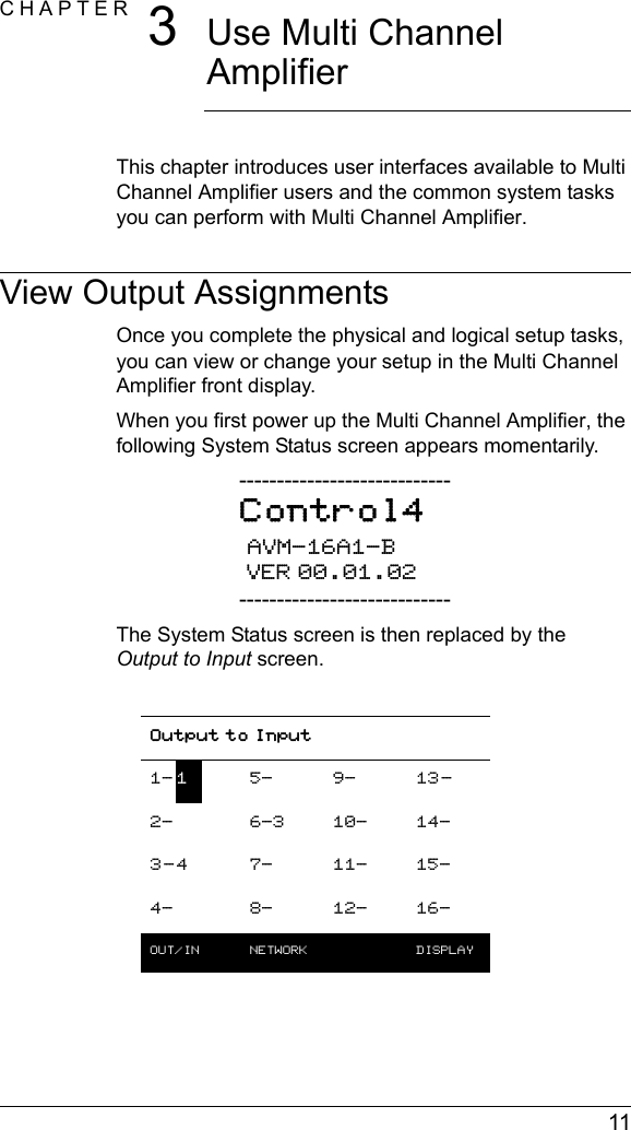
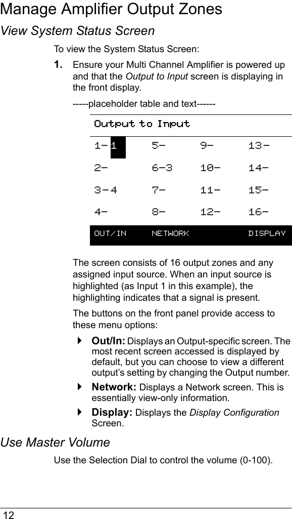
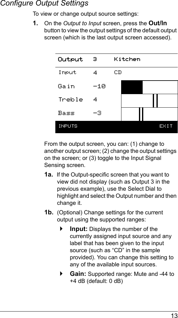
Control4 AVM16A11 Multi Channel Amplifier AVM-16A1-B User Manual MultiChannelAmp

Control4 Multi Channel Amplifier AVM-16A1-B MultiChannelAmp

Exhibit 8

DisclaimerControl4® makes no representations or warranties with respect to the contents or use of this manual, and specifically disclaims any express or implied warranties of merchantability or fitness for any particular purpose. Control4 reserves the right to revise this publication and to make changes to its content, at any time, without obligation to notify any person or entity of such revisions or changes.Control4 makes no representations or warranties with respect to any Control4 software, and specifically disclaims any express or implied warranties of merchantability or fitness for any particular purpose. Control4 reserves the right to make changes to any and all parts of Control4 software and hardware, at any time, without any obligation to notify any person or entity of such changes.TrademarksControl4 and the Control4 logo are registered trademarks of Control4 Corporation. Other product and company names mentioned in this document may be the trademarks or registered trademarks of their respective owners.Legal NoticeGracenote. Music recognition technology and related data are provided by Gracenote. Gracenote is the industry standard in music recognition technology and related content delivery. For more information visit www.gracenote.com. Copyright Copyright © 2004-2005 Control4. All rights reserved. No part of this publication may be reproduced, photocopied, stored on a retrieval system, or transmitted without the express written consent of the publisher.Contact UsControl4 Corporation11734 S. Election Road, Suite 200Salt Lake City, UT 84020 USAhttp://www.control4.comMulti Channel Amplifier - 16 Installation and User GuidePart Number: 21-0150 Rev A Draft 3Hardware Model Number: AVM-16A1-B
 iContentsPreface About This Guide........................................... 1Notes, Tips, Cautions, and Warnings .... 1Additional Resources............................. 2Chapter 1 Introduction to Multi Channel Amplifier - 16... 3Features and Benefits............................ 3Home Network Requirements................ 4What’s in the Box................................... 4About the Multi Channel Amplifier ......... 4Front View......................................... 4Back View ......................................... 5Chapter 2 Install the Multi Channel Amplifier ................. 7Plan Your Physical Layout..................... 7Connect Physical Components.............. 9Set Up Logical Connections .................. 9Chapter 3 Use Multi Channel Amplifier ........................ 11View Output Assignments.................... 11Manage Amplifier Output Zones .......... 12View System Status Screen ........... 12Use Master Volume ........................ 12Configure Output Settings .............. 13View Network Settings......................... 14Set Display Preferences ...................... 15Chapter 4 Warranty and FCC Information.................... 17Warranty .............................................. 17Limited Hardware Warranty ............ 17Hardware Warranty Terms ............. 18Software Agreement ....................... 21Regulatory Compliance ....................... 22
 iiFCC Interference Statement........... 22FCC Caution ................................... 23Canadian EMC Statement .............. 23
 1PREFACEAbout This GuideNotes, Tips, Cautions, and WarningsAudio Matrix Switch Installation and User Guide Note, Tip, Caution, and Warning paragraphs draw your attention to safe practices and additional information which may help you avoid losing data or time.NOTE:  These contain notes on related information about the current topic. TIP:  These provide tips that may save you time or effort.CAUTION!  These provide specific cautions about improper use of equipment or failure to follow safety instructions that may cause bodily injury. DO NOT IGNORE A CAUTION!WARNING!  These provide specific warnings about improper use of equipment or failure to follow safety instructions that may cause data loss or equipment damage. DO NOT IGNORE A WARNING!
 2Additional ResourcesThe following resources are available to provide you with additional support. `Your authorized Control4 representative or reseller.`Control4 Web Site: http://www.Control4.com/
 3CHAPTER 1Introduction to Multi Channel Amplifier - 16Multi Channel Amplifier - 16 can operate independently or as a device you can control with your Control4 system. It is used when the installation requires remote placement of amplifiers and/or special power requirements.This Multi Channel Amplifier is intended for use in a Control4 system and is typically used in conjunction with the Audio Matrix Switch or a controller.This chapter introduces the Control4 Multi Channel Amplifier - 16 and its features.Features and Benefits`Receives up to 16 mono or 8 stereo inputs.`Outputs 16 mono or 8 stereo class D amplified channels at 100 watts per channel.`Front display for adjusting zone settings and routing sources (includes an LCD, supporting buttons, and a selection dial)`Adjustable gain, treble, and bass for each zone. `Master Volume Control for all outputs.`Control4 EZ ID™ LEDs for every I/O to make connections easy to identify.`Device chassis is three standard rack spaces and rack mountable configuring to EIA 19” rack standards (its dimensions are 5.25” x 17.34” x 14”).`Communicates via Ethernet 10/100 port and ZigBee mesh networking (802.11.15).`Backlighting feature turns on with any button push or Select Dial push and stays lit for a preset time (default is 30 seconds).
 4Home Network RequirementsEnsure that your home network wiring is in place before starting your system setup. Multi Channel Amplifier requires an Ethernet connection in order to be managed and controlled from the Control4 user interfaces. What’s in the BoxThe following hardware and software is required and included in your Control4 Multi Channel Amplifier box.`Control4 Multi Channel Amplifier - 16`IEC power cord`This manualAbout the Multi Channel AmplifierFront View1.  Front Display—For displaying or setting Multi Channel Amplifier settings and navigating system menus. The front display is used to view or modify audio source routing and zone settings for volume, gain, bass, and treble. The display also shows the current source and zone activity. 12453
 52.  Buttons—Provides the user-input method for options displayed in the front panel user interface.3.  IR Window—For reading IR signals from devices such as a remote control.4.  Select Dial—For scrolling through menus and media lists displayed in the LCD.5.  Reset Button—Troubleshooting option behind the door to refresh the system.Back View 1.  Ethernet Port—RJ-45 for a 10/100 Baset Ethernet connection.2.  Audio Inputs 1-16—RCA jacks for 16 mono or 8 stereo analog sources and their supporting light emitting diodes (LEDs) for EZ ID™ during setup.3.  Amplifier Outputs 1-16—5-way binding post for 16 mono or 8 stereo class D amplified channels (at 100 watts per channel) and their supporting LEDs for EZ ID™ during setup.4.  Power Plug Port—For supplied power cord only.1342
 6
 7CHAPTER 2Install the Multi Channel AmplifierThis chapter describes, in general terms, how to set up the physical connections required for Multi Channel Amplifier and all of the devices associated with it. You should also refer to any installation documentation available for the devices you plan to connect for additional guidelines.In order to use the multi-channel amplifier as designed, you must complete the following tasks: 1.Plan Your Physical Layout2.Connect Physical Components3.Set Up Logical ConnectionsNOTE:  To set up the logical connections required, trained installers must use the Control4 Composer Pro software. For instructions, refer to the Composer Pro User Guide.Plan Your Physical LayoutThis section explains physical and logical connections and can help you plan your physical connections.Use a worksheet to plan your amplifier connections: Using the worksheet provided in Table 2-1 on page 8, identify the connection you will use for all planned connections.
 8Table 2-1. Multi Channel Amplifier Connection WorksheetAudio Input—16 mono or 8 stereo sourcesInput examples: CD changers, VCRs, TVs, DVD changers, Media Controller.Amplifier Output— 16 mono or 8 stereo channel outputs Output examples: Speakers or Audio Matrix Switch.1616151514141313121211111010998877665544332211
 9Connect Physical ComponentsFor the hardware you want included in the system, connect the applicable devices to Multi Channel Amplifier.NOTE:  If you used Table 2-1 (on the previous page) to plan your connections, refer to it now to help you complete the following steps.1. Connect all Audio Input devices.2. Connect all Amplifier Output devices.3. If you are using an Ethernet connection for Multi Channel Amplifier, plug the data cable from the home network connection into the Multi Channel Amplifier RJ-45 port (labeled “Ethernet”) and the network port in your wall or at the network hub or switch.4. Connect the power cord provided to the back of the Multi Channel Amplifier and to the power outlet.With the physical connections completed, you are ready to complete the logical connections. Set Up Logical ConnectionsPhysical and logical connections are required in order to control, navigate, and use the Multi Channel Amplifier as designed. Thus far you have set up the physical connections for the Control4 Multi Channel Amplifier. To complete the logical setup, use Control4 Composer Pro software (available to trained installers only) installed on a PC connected to the home network. For instructions, refer to the Control4 Composer Pro User Guide.
 10
 11CHAPTER 3Use Multi Channel AmplifierThis chapter introduces user interfaces available to Multi Channel Amplifier users and the common system tasks you can perform with Multi Channel Amplifier.View Output AssignmentsOnce you complete the physical and logical setup tasks, you can view or change your setup in the Multi Channel Amplifier front display. When you first power up the Multi Channel Amplifier, the following System Status screen appears momentarily.----------------------------Control4 AVM-16A1-B VER 00.01.02----------------------------The System Status screen is then replaced by the Output to Input screen.Output to Input1- 15- 9- 13-2- 6-3 10- 14-3-4 7- 11- 15-4- 8- 12- 16-OUT/IN  NETWORK  DISPLAY
 12Manage Amplifier Output ZonesView System Status ScreenTo view the System Status Screen:1. Ensure your Multi Channel Amplifier is powered up and that the Output to Input screen is displaying in the front display.-----placeholder table and text------The screen consists of 16 output zones and any assigned input source. When an input source is highlighted (as Input 1 in this example), the highlighting indicates that a signal is present.The buttons on the front panel provide access to these menu options:`Out/In: Displays an Output-specific screen. The most recent screen accessed is displayed by default, but you can choose to view a different output’s setting by changing the Output number. `Network: Displays a Network screen. This is essentially view-only information.`Display: Displays the Display Configuration Screen.Use Master VolumeUse the Selection Dial to control the volume (0-100).Output to Input1- 15- 9- 13-2- 6-3 10- 14-3- 4 7- 11- 15-4- 8- 12- 16-OUT/IN  NETWORK  DISPLAY
 13Configure Output SettingsTo view or change output source settings:1. On the Output to Input screen, press the Out/In button to view the output settings of the default output screen (which is the last output screen accessed).From the output screen, you can: (1) change to another output screen; (2) change the output settings on the screen; or (3) toggle to the Input Signal Sensing screen.1a.  If the Output-specific screen that you want to view did not display (such as Output 3 in the previous example), use the Select Dial to highlight and select the Output number and then change it.1b.  (Optional) Change settings for the current output using the supported ranges:`Input: Displays the number of the currently assigned input source and any label that has been given to the input source (such as “CD” in the sample provided). You can change this setting to any of the available input sources.`Gain: Supported range: Mute and -44 to +4 dB (default: 0 dB)Output 3 KitchenInput 4CDGain -10Treble 4Bass -3INPUTS   EXIT
 14`Treble: Supported range: -10 to +10 dB (default: 0 dB)`Bass: Supported range: -10 to +10 dB (default: 0 dB)1c.  If you want to toggle to view Input Signal Sensing information, choose the Inputs button. 1d.  If you want to Exit the screen, choose the Exit button.2. Rotate the Select Dial to highlight a setting.3. Press the Select Dial to enter Edit mode.4. Rotate the dial to change the setting; then press the dial to Save the new setting and exit the Edit mode OR, to exit without saving, use the front panel button indicated to choose the Cancel option.5. Press the Inputs button to go to the Input Signal Sensing screen, OR press the Exit button to return to the Output to Input screen.View Network SettingsTo view network settings, access the Network settings screen. These are view-only fields: MAC Address, DHCP, IP Address, Subnet Mask, and Default Gateway Configuration. By default, the system uses DHCP.
 15Set Display PreferencesTo set your viewing preferences for the front display:1. On the Output to Input screen, press the Display button. The Display Configuration screen displays.Network - EthernetMAC 00:00:00:00:00:00DHCP enabledIP 255.255.255.255Mask 0.0.0.0GWay 0.0.0.0    EXITDisplay ConfigurationBrightness: 100Contrast: 100Backlight Time: 10 DOWN UP  SELECT EXIT
 162. Use the buttons and/or the Select Dial to choose a setting to change: Once you press the Select button (or press the dial), you enter Edit mode.3. In Edit mode, use the buttons or Select Dial to change the highlighted setting; then press the OK button (or press the dial) to save the change and exit Edit mode.Brightness: Supported range: 0 to 100 Contrast: Supported range: 0 to 100 Backlight Timeout: Supported settings are: `OFF (Always Off)`1 to 90 seconds (default is 30 seconds)`ON (Always On)Display ConfigurationBrightness: 100Contrast:  100Backlight Time: 10 DOWN UP  SELECT EXIT
 17CHAPTER 4Warranty and FCC InformationWarrantyImportant: Warranty terms may be different with the country of purchase; contact your Authorized Control4 Sales and Service office for detailed product warranty information.Limited Hardware WarrantyControl4 warrants its Multi Channel Amplifier - 16 product to be free from defects in material and workmanship during the warranty period. If the Multi Channel Amplifier proves to be defective in material or workmanship during the warranty period, Control4 will, at its sole option, repair or replace the product with a like product. The warranty extends only to products purchased directly from Control4 Corporation or an Authorized Control4 Dealer.How long the warranty is effective: Control4 Multi Channel Amplifier are warranted for one (1) year from the date of the first consumer purchase.What the warranty does not cover:`Misuses; unauthorized modification; opening for any reason except to perform an official upgrade using an proper tools/kit`Operation or storage outside the environmental specifications for the product`The battery, or damage caused by this battery`In-transit damage and improper maintenance`Physical damage to the unit, such as a cracked or broken screen or defect resulting from use of improper software, accessories, media, supplies, consumables, or such items not designed for use with the product.
 18Hardware Warranty TermsREAD THESE WARRANTY TERMS CAREFULLY BEFORE INSTALLING OR USING THE CONTROL4 SYSTEM OR COMPONENTS.  YOUR INSTALLATION AND USE OF THE SYSTEM OR ANY OF ITS COMPONENTS INDICATES THAT YOU AGREE TO BE BOUND BY THESE TERMS.  IF YOU DO NOT AGREE TO ALL OF THE TERMS OF THIS WARRANTY, RETURN THE PRODUCT TO THE PLACE OF PURCHASE FOR A FULL REFUND. ONE-YEAR LIMITED WARRANTY1.    WARRANTYControl4, Corporation. ("Control4") warrants that at the time of sale the Multi Channel Amplifier (the “product”) will be free from defects in material and manufacture and will conform to Control4's specifications for the components.  Control4 further warrants that for a period of 12 months after sale the product will function in accordance with its specification, PROVIDED THAT it is installed and maintained in accordance with Control4's instructions and is not subjected to (a) alteration or unauthorized repairs, (b) misuse or abuse, (c) Acts of God (including without limitation hurricanes, tornadoes, floods, earthquakes, or other severe weather or natural phenomena), or (d) improper storage or handling or other treatment or installations for which it was not intended. This warranty extends only to products purchased directly from Control4 or an Authorized Control4 Dealer. 2.    DISCLAIMER OF OTHER WARRANTIESThe preceding warranties are the exclusive and sole express warranties given by CONTROL4.  They supersede any prior, contrary or additional representations, whether oral or written.  CONTROL4 HEREBY DISCLAIMS AND EXCLUDES ALL OTHER WARRANTIES-WHETHER EXPRESS, IMPLIED, OR STATUTORY-INCLUDING ANY ARISING FROM COURSE OF DEALING OR USAGE OF TRADE, ANY WARRANTY OF
 19MERCHANTABILITY AND ANY WARRANTY OF FITNESS FOR A PARTICULAR PURPOSE, except that for product purchased directly by a consumer, any implied warranties are limited in duration to the term of the express warranties provided above.Some states do not allow limitations on how long an implied warranty lasts, so the above limitation may not apply to you.3.    EXCLUSIVE REMEDY FOR ANY NONCONFORMITIES If during the applicable Warranty Period, the product does not conform to the preceding Warranties, the Owner shall notify Control4 as provided below, and within a reasonable time Control4 will provide, at its option, one of the following:  (1) a replacement product for any nonconforming or defective component (such replacement product may be new or refurbished to be comparable in function and performance to a new product) or (2) the price at which Control4 sold the non-conforming product.  In the event of repair or replacement, there may be a loss of data in the memory of the product for which warranty service is sought.  Control4 will not provide, and will not be liable for, labor, costs of removal or reinstallation of product, disposal, freight, taxes, or other incidental charges.THESE REMEDIES ARE THE EXCLUSIVE AND SOLE REMEDIES FOR ANY BREACH OF WARRANTY. For any breach of warranty, the Owner must notify Control4 in Section 7 below within thirty (30) days after discovering the nonconformity.  The notice must describe the location and nature of the nonconformity.  The owner must give Control4 a reasonable opportunity to the claimed nonconformity before undertaking any repairs, removal or replacement. All products returned to Control4 require a Return Merchandise Authorization (RMA) number. The RMA number is obtained from Control4 Customer Support Department. The RMA number must be clearly marked on the outside of each box. The RMA is valid for a 30-day period. After the 30-day period, the
 20RMA will be cancelled. Any shipments received not consistent with the RMA, or after the RMA is cancelled, will be refused. Control4 is not responsible for products returned without a valid RMA number. Compliance with the requirements of this paragraph is a condition to coverage under the Warranty: If these requirements are not complied with, Control4 will have no obligation to provide any remedy for any breach of warranty.4.    DISCLAIMER OF INCIDENTAL AND CONSEQUENTIAL DAMAGESIN NO EVENT SHALL CONTROL4 BE LIABLE FOR ANY INCIDENTAL, SPECIAL, INDIRECT OR CONSEQUENTIAL DAMAGES, WHETHER RESULTING FROM NONDELIVERY OR FROM THE USE, MISUSE OR INABILITY TO USE THE PRODUCT OR FROM DEFECTS IN THE PRODUCT OR FROM CONTROL4'S OWN NEGLIGENCE.  This exclusion applies even if the remedy provided by Control4 fails of its essential purpose.Some states do not allow the exclusion or limitation of incidental or consequential damages, so the above limitation may not apply to you.  5.    APPLICABLE LAWThis Warranty will be interpreted, construed, and enforced in all respects in accordance with the laws of the State of Utah, without reference to its choice of law rules.  The U.N. Convention on Contracts for the International Sale of Goods will not apply to this Warranty.  6.    SEVERABILITYIf any provision of this warranty is found to be invalid or unenforceable, then the remainder shall have full force and effect, and the invalid provision shall be partially enforced to the maximum extent permitted by law to effectuate the purpose of the agreement.
 217.    ADDRESS FOR NOTICES TO CONTROL4Control4 Corporation11734 Election Road, Suite 200Salt Lake City, UT  84020Fax # 801-523-3199Telephone # 801-523-3100This warranty gives you specific legal rights, and you may also have other rights which vary from State to State.Software Agreement The Control4 Multi Channel Amplifier contains preinstalled software. Please read the following Control4 terms before proceeding:NOTE:  Carefully read this License Agreement and the Limited Warranty statement before operating the equipment. The rights to the software are licensed, not sold. Control4 or its licensors continue to own all intellectual property rights to the software, and you will be granted certain rights to use the software upon your acceptance of this license. Rights in the software are offered only on the condition that you agree to all terms and conditions of the License Agreement. Operating the equipment indicates your acceptance of these terms and conditions. If you do not agree to the terms and conditions of the License Agreement, return the complete package for a full refund now. Terms that Govern Software UseYou may only use the software as designed on the device on which it comes pre-installed. You may not reverse, assemble, or decompile the software.
 22Limited Software Warranty, Liability, and RemedyImportant: This Control4 Software Limited Warranty shall cover all software that is provided to you, the customer, as part of the Control4 product, including any operation system software. The Remedies provided in this document are your sole and exclusive remedies. In no event shall Control4 be liable for any direct, indirect, special, incidental, or consequential damages (including lost profit), whether based on warranty, contract, tort, or any other legal theory.In no case shall Control4's liability exceed the purchase price for the software and/or product. The limitations set forth above will apply regardless of whether you accept the software. Regulatory ComplianceThis product complies with standards established by the following regulatory bodies:Federal Communications Commission (“FCC”)Canadian Electromagnetic Compatibility (“EMC”)FCC Interference StatementThis equipment has been tested and found to comply with the limits for a Class B digital device, pursuant to Part 15 of the FCC Rules.  These limits are designed to provide reasonable protection against harmful interference in a residential installation.  This equipment generates uses and can radiate radio frequency energy and, if not installed and used in accordance with the instructions, may cause harmful interference to radio communications.  However, there is no guarantee that interference will not occur in a particular installation.  If this equipment does cause harmful interference to radio or television reception, which can be determined by turning the equipment off and on, the user is encouraged to try to correct the interference by one of the following measures:`Reorient or relocate the receiving antenna.
 23`Increase the separation between the equipment and receiver.`Connect the equipment into an outlet on a circuit different from that to which the receiver is connected.`Consult the dealer or an experienced radio/TV technician for help.FCC Caution Any changes or modifications not expressly approved by the party responsible for compliance could void the user's authority to operate this equipment.This device complies with Part 15 of the FCC Rules. Operation is subject to the following two conditions: (1) This device may not cause harmful interference, and (2) this device must accept any interference received, including interference that may cause undesired operation.Canadian EMC StatementThis Class B digital apparatus complies with Canada ICES-003.Cet appareil numérique de la classe B est conforme à la norme NMB-003 du Canada.
 24

Navigation menu