Control4 C4THERM THERMOMETER User Manual
Control4 THERMOMETER
UserManual.wiki
>
Control4
>
C4THERM User Manual
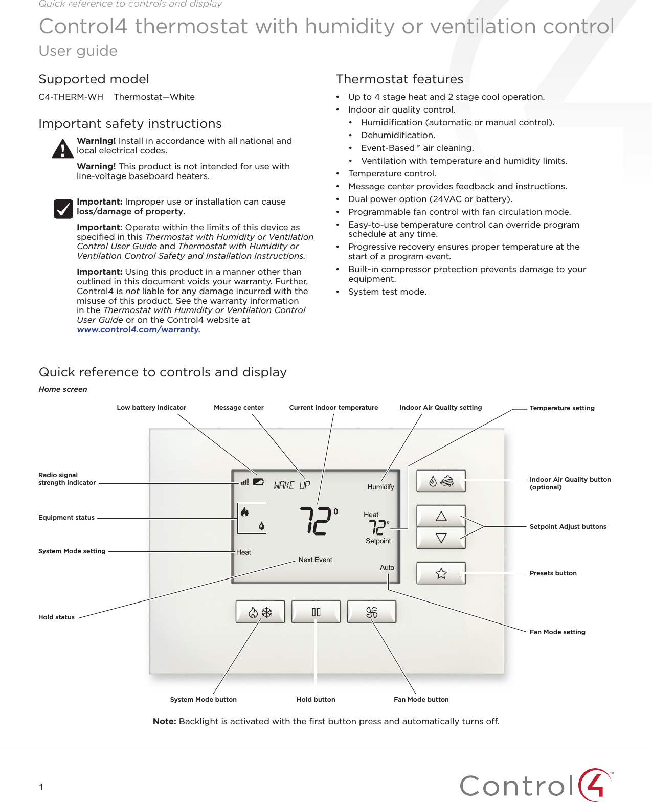
User manual
Navigation menu
Upload a User Manual
Namespaces
Wiki Guide
HTML
PDF
Info
Views
User Manual
Discussion / Help
Navigation

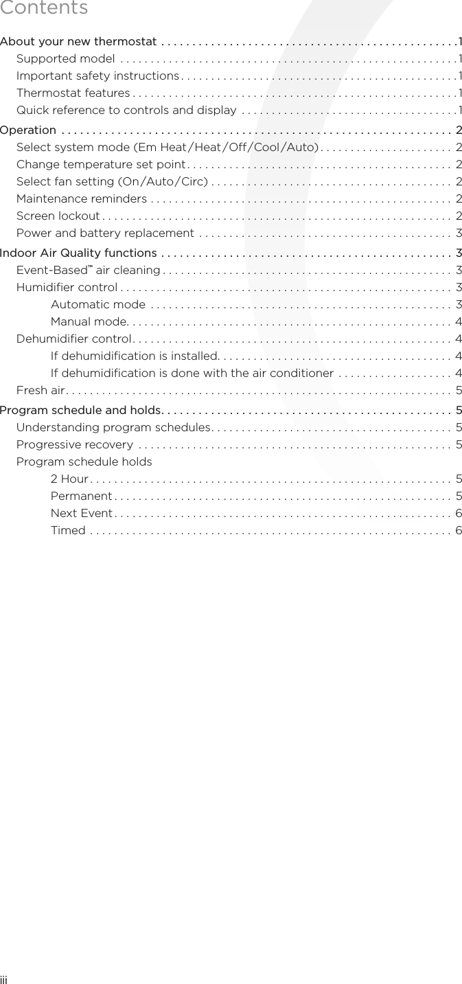

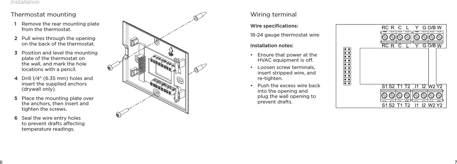
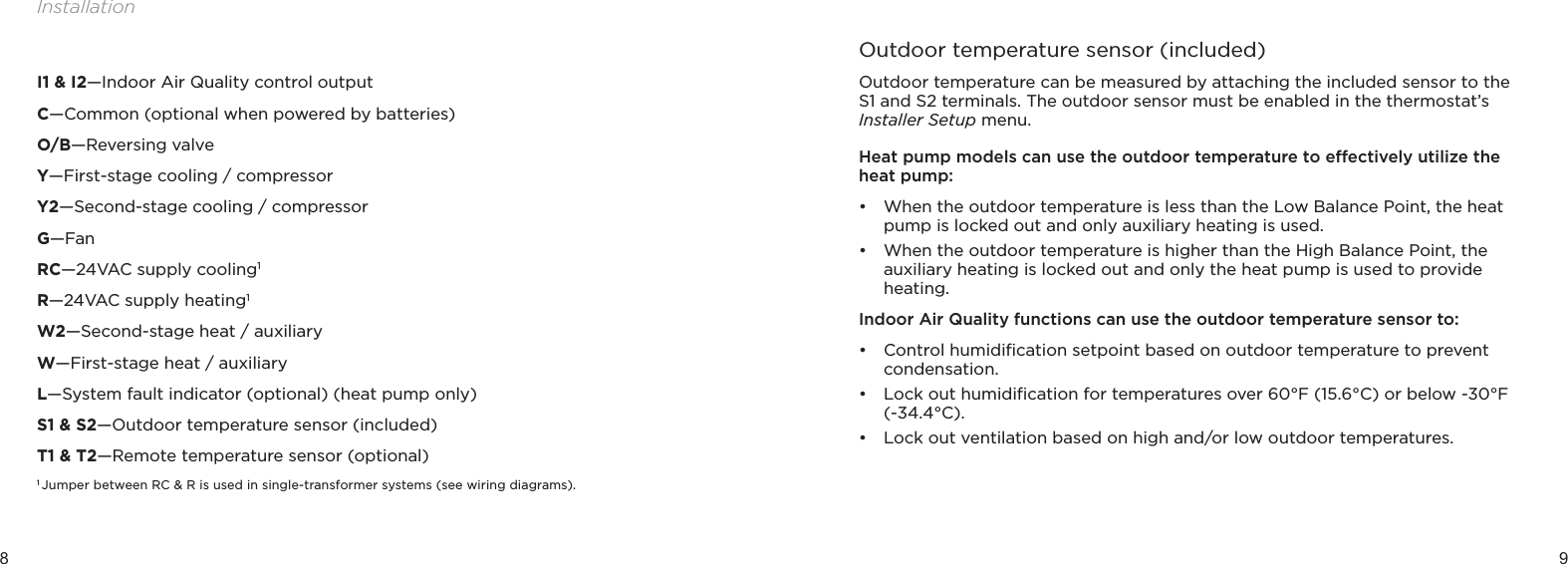
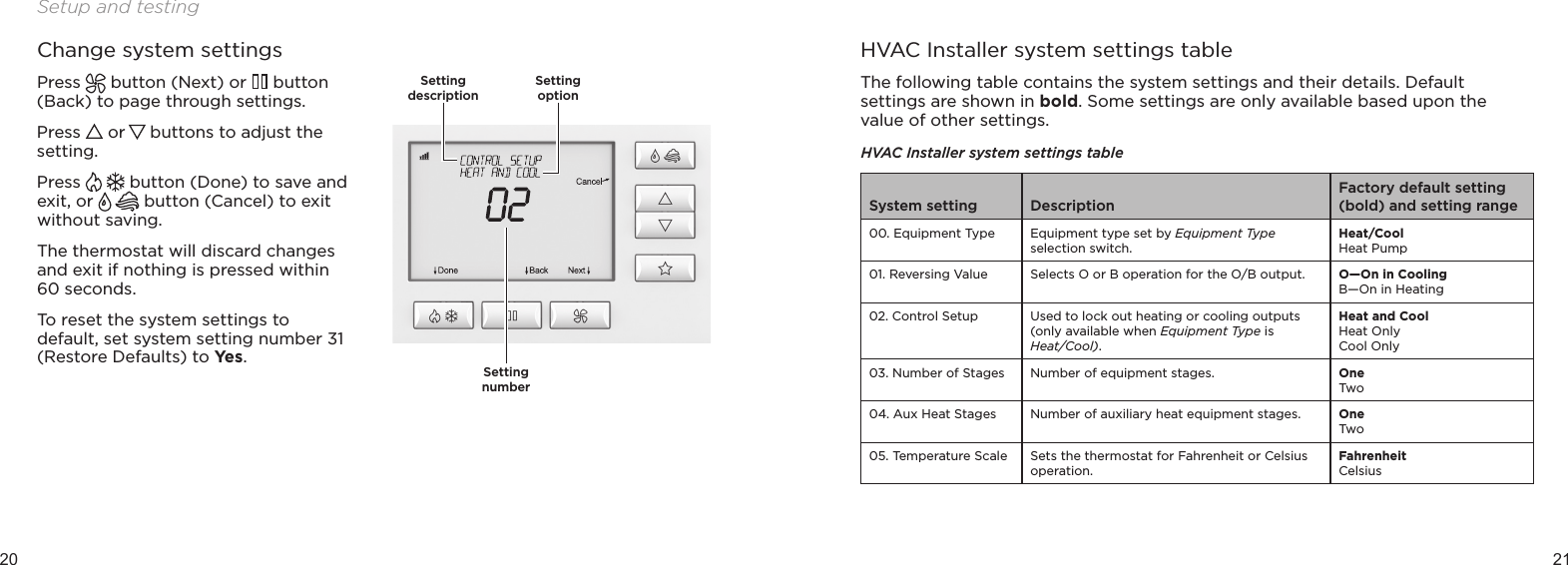
![10 11InstallationY2I1 W2S2S1 T1 T2 I2GYO/B WRC RLCGYO/BWRCRLCY2I1 W2S2S1 T1 T2 I2The outdoor temperature sensor should be mounted:• On the side of the building out of direct sunlight (north side recommended).• Above snow line.• At least 3' (about 1 meter) away from exhaust vents and condensing lines.• Using less than 300' (about 100 meters) of wire.• Do not route wires parallel to 120VAC lines.A remote temperature sensor can be used if the thermostat is going to be mounted in a concealed location. Additionally, Control4 programming can be utilized to switch between the on-board temperature sensor and the remote temperature sensor, allowing the temperature reading to come from dierent areas based on time of day or daily activity. A AC-FMTS1-W flush mount or AC-DOTS1-W surface mount remote temperature sensor can be attached to the T1 and T2 terminals and mounted in a recommended area. The remote sensor must be enabled in the thermostat’s Installer Setup menu. When the remote sensor is selected as the primary sensor (System Setting 14 [Primary Sensor]), it overrides the internal sensor.Y2I1 W2S2S1 T1 T2 I2GYO/B WRC RLCGYO/B WRC RLCY2I1 W2S2S1 T1 T2 I2Remote temperature sensor (optional)](https://usermanual.wiki/Control4/C4THERM/User-Guide-2521117-Page-18.png)