Control4 C4Z2IO Zigbee to IO transceiver User Manual
Control4 Zigbee to IO transceiver
UserManual.wiki
>
Control4
>
C4Z2IO User Manual
User Manual
Navigation menu
Upload a User Manual
Namespaces
Wiki Guide
HTML
PDF
Info
Views
User Manual
Discussion / Help
Navigation
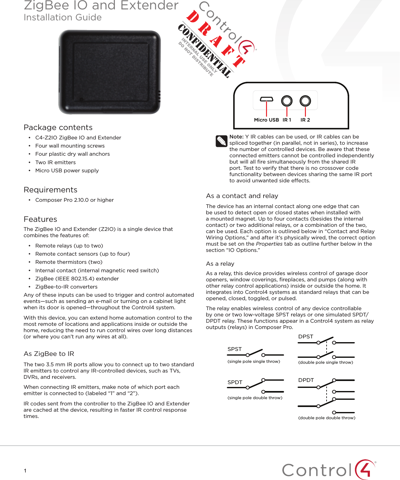
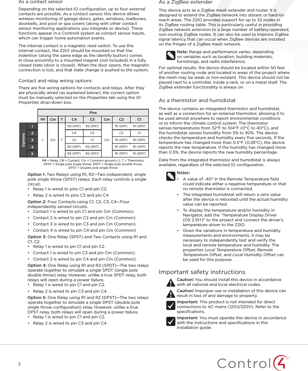
![55Tip: Two SPST relays can optionally be linked to simulate a single SPDT relay. However, unlike a true SPDT relay, both relays will open during a power failure.4 Add generic contact drivers (such as Door Contact Sensor, Gate, and Motion Sensor) and relay drivers (such as Blinds, Door Lock, and Pump) in System Design view, then connect the generic driver to the appropriate connection on the C4-Z2IO device in Connections view.5 For programming, use these events:• Online: Triggers when the device comes online.• Oine: Triggers when the device goes oine.• Reboot: Triggers when the device reboots.PropertiesGeneral properties• Log Level: Standard for most drivers, this property allows you to filter which message types display in the Lua Output window. Options 0 - 5 correspond to Fatal through Trace levels, increasing in level of verbosity. Options are 0=Fatal, 1=Error, 2=Warning, 3=Info, 4=Debug, and 5=Trace. Default is 1 - Error. • Log Mode: Activates logging of diagnostic information. The log level is set in the above property. Options include O, Print (to the window), Log (to the Director Log), and Print and Log (both). Default is O. • Driver Version: (Read only) Shows the version number of the driver currently in use. • Device Status: (Read only) Shows the current status of the product, whether online or oine. However, in some cases, the device may not report its status immediately, such as when the device is rebooting. • Firmware Version: (Read only) Shows the version number of the firmware currently in use on the device. The firmware will be updated automatically over the air when the Control4 OS is updated and when that update includes a new firmware version for this device. • Bootloader Version: (Read only) Shows the version number of the firmware currently in use on the device. The bootloader can only be updated by Control4, so this property is for support/diagnostic information only. • LED Mode: Determines the behavior of the LED light on the top/front of the product. Options include O, ZigBee (which shows the ZigBee status; see “Identification and Button Presses” below), and IR (which shows activity when IR signals are sent to the IR ports). Default is O. When the property is set to O, button presses should still temporarily prompt the LED to show the status.Humidity prperties• Local Humidity: (Read only) Shows the relative humidity measured where the device is located. The value is shown as a percentage. • Local Humidity Oset: The humidity sensor provides accuracy of +/- 4% relative humidity. Adjusting the Local Humidity Oset can result in increased inaccuracy of relative humidity reporting without using humidity calibration equipment for validation.Temperature and humidity properties• Temperature Scale: Sets which scale is used to calculate the temperature used in the Local and Remote Temperature properties described below, and aects only the Properties tab’s settings. Options include Fahrenheit and Celsius. Default is Fahrenheit.• Local Temperature: (Read only) Shows the most recent reported temperature recorded by the internal thermistor. The scale of the temperature is determined by the Temperature Scale property. • Local Temperature Oset—Modifies the reported local temperature to account for environmental variances. The temperature can be changed downward or upward by a maximum of 20 degrees. The default is 0 (no correction). • Remote Temperature: (Read only) Shows the most recent reported temperature recorded by the remote thermistor. The scale of the temperature is determined by the Temperature Scale property. • Remote Temperature Oset—Modifies the reported remote temperature (the temperature recorded by an external thermistor) to account for environmental variances. (When multiple temperature sensors are located in the same room, you may notice each sensor shows a slightly dierent reading. This results from normal manufacturing variances in temperature sensors and the device’s position/location in the room.) The temperature can be changed downward or upward by a maximum of 20 degrees. The default is 0 (no correction).IO properties• IO Options: Tells the device how its eight configuration pins are assigned. The selected option is retained even after a system reboot or update. PinsPWRCm TR2CmR1C4 C3 C2 C1Options1+ Cm TR2 (SPST)R2 (SPST)CmR1 (SPST)R1 (SPST)2C4 C3 C2 C13C2 C1 R1 (SPST)R1 (SPST)4R2 (SPDT)R2 (SPDT)R1 (SPDT)R1 (SPDT)5R2 (DPST)R2 (DPST)R1 (DPST)R1 (DPST)R# = Relay, C# = Contact, Cm = Common ground (-), T = Thermistor, SPST = Single pole single throw, SPDT = Single pole double throw, DPST = Double pole single throw• Option 1: R1, R2 (both SPST [single pole single throw]): (Default) Both relays are single pole single throw, meaning they are independent of each other; or, in other words, each relay controls only one circuit.• Option 2: C1, C2, C3, C4: Four contacts. • Option 3: R1 (SPST), C1, C2: One relay (single pole single throw) and two contacts.• Option 4: R1 (SPDT [single pole double throw]): The two relays operate together to simulate a single SPDT (single pole double throw) relay. However, unlike a true SPDT relay, both relays will open during a power failure.• Option 5: R1 (DPST [double pole single throw]): The two relays operate together to simulate a single DPST (double pole single throw configuration) relay.Notes: • The ZigBee extender, IR emitter control, internal contact, internal thermistor, and internal humidistat remain active regardless of the selected IO configuration.• The selected IO option will change the available connections, so existing connections will be disconnected or deleted.• The selected IO option determines the available fields in Contact properties and Relay properties.Contact properties](https://usermanual.wiki/Control4/C4Z2IO/User-Guide-3548582-Page-5.png)
![6• Contact Internal Status: (Read only) Shows the status of the static connection for the internal contact.• Contact 1-4 Status: (Read only) Represents the status of the wired contacts if IO Option 1, 3, 4, or 5 is selected.Relay properties• Relay 1 Power Up State and Relay 2 Power Up State: (Read only) Represents the status of the relays if IO Option 1, 3, 4, or 5 is selected. The options are Restore Last State, Set To OPEN, and Set To CLOSED. The default is Restore Last State.• Relay 1 Status and Relay 2 Status: (Read only) Represents the status of the relays if IO Option 1, 3, 4, or 5 is selected. Actions tabButtons located on the Actions tab allow you to view version and diagnostic information and force relay actions. (Relay actions will always be shown, regardless of the IO configuration.)• Version Information: This action button will display the versions of the driver’s Base Template and Template, as well as the Boot Loader to the Lua Output window of the Lua tab. The Log Mode property does not have to be set to Print to display this information to the window.• Diagnostic Information: This action button will display the following information to the Lua Output window of the Lua tab (the Log Mode property does not have to be set to Print to display this information to the window): device ZigBee MAC address, ZigBee mesh PAN id, Template Version, Base Template Version, Boot Loader Version, ZigBee Node ID.• Relay 1 Close and Relay 2 Close: These action buttons will trigger the corresponding relay to close.• Relay 1 Open and Relay 2 Open: These action buttons will trigger the corresponding relay to open.TroubleshootingIf the device is not working:• Reboot the device by disconnecting power, then re-connecting power.• Check for proper wiring. See the “Wiring Configuration” diagrams.• Review the log in the driver’s Lua tab.• Restore factory defaults (13 button presses).Note: Un-identifying a device o the ZigBee mesh will cause it to do a factory reset. A factory reset reverts all relays to the open state, and the settings for Power Up State will revert to Restore Last State. The settings are preserved, however, after a power cycle or reboot.LED diagnosticsThe indicated statuses appear during device identification and when the ID button is pressed once.LED Description[Green] On Oine/Waiting for Director[Yellow] Slow flashing Scanning[Blue] On Join success[Green] Fast flashing Join success signal strength=good[Yellow] Fast flashing Join success signal strength=adequate[Red] Fast flashing Join success signal strength=risk/low[Red] Medium flashing Join failed (then returns to oine)[Green] Slow flashing Signal strength=good (from Network Tools)[Yellow] Slow flashing Signal strength=adequate (from Network Tools)[Red] Slow flashing Signal strength=risk/low (from Network Tools)Button sequencesFunctions # of button pressesIdentify 4Reboot/Reset 15Reset application defaults 9Leave mesh, restore factory defaults 13Signal strength flash LEDs 1Restoring to previous firmware version1 Power o the device (disconnect power).2 While holding down the ID button, reconnect power, and continue to press the ID button until the LED changes from red to white (about five seconds).3 Release the button. The device will reboot to its previous firmware version in about one minute.](https://usermanual.wiki/Control4/C4Z2IO/User-Guide-3548582-Page-6.png)
![4Temperature properties• Temperature Scale: Sets which scale is used to calculate the temperature used in the Local and Remote Temperature properties described below, and aects only the Properties tab’s settings. Options include Fahrenheit and Celsius. Default is Fahrenheit.• Local Temperature: (Read only) Shows the most recent reported temperature recorded by the internal thermistor. The scale of the temperature is determined by the Temperature Scale property. • Local Temperature Oset—Modifies the reported local temperature to account for environmental variances. The temperature can be changed downward or upward by a maximum of 20 degrees. The default is 0 (no correction). • Remote Temperature: (Read only) Shows the most recent reported temperature recorded by the remote thermistor. The scale of the temperature is determined by the Temperature Scale property. • Remote Temperature Oset—Modifies the reported remote temperature (the temperature recorded by an external thermistor) to account for environmental variances. (When multiple temperature sensors are located in the same room, you may notice each sensor shows a slightly dierent reading. This results from normal manufacturing variances in temperature sensors and the device’s position/location in the room.) The temperature can be changed downward or upward by a maximum of 20 degrees. The default is 0 (no correction).Contacts properties• Contact Internal Status: (Read only) Shows the status of the static connection for the internal contact.• Contact 1-4 Status: (Read only) Represents the status of the wired contacts.Checkin properties• Checkin Interval: Defines how often the device checks with the controller to see if the controller is requesting information from the device, such as version information, or if the controller is trying to update any settings on the device, such as the check in interval. A check in can also be manually triggered by pressing the button on the Z2C. The check-in interval can be configured to check in with the controller between 10 minutes and 4 hours. The default is 10 minutes. Increasing the check-in interval will increase the battery life of the device.• Last Checkin Time: (Read only) Shows the most recent time the device checked in with the controller.• Missed Checkin Limit: Sets the number of times the checkin is missed before triggering the “Missed Checkin” programming event.Actions tabButtons located on the Actions tab allow you to view version and diagnostic information.• Version Information: This action button will display the versions of the driver’s Base Template and Template, as well as the Boot Loader to the Lua Output window of the Lua tab. The Log Mode property does not have to be set to Print to display this information to the window.• Diagnostic Information: This action button will display the following information to the Lua Output window of the Lua tab (the Log Mode property does not have to be set to Print to display this information to the window): device ZigBee MAC address, ZigBee mesh PAN id, Template Version, Base Template Version, Boot Loader Version, ZigBee Node ID.TroubleshootingIf the device is not working:• Reboot the device by disconnecting power, then re-connecting power.• Check for proper wiring. See the “Wiring Configuration” diagrams.• Review the log in the driver’s Lua tab.• Restore factory defaults (13 button presses).Note: Un-identifying a device o the ZigBee mesh will cause it to do a factory reset. The settings are preserved, however, after a power cycle or reboot.LED diagnosticsThe indicated statuses appear during device identification and when the ID button is pressed once.LED Description[Green] On Oine/Waiting for Director[Yellow] Slow flashing Scanning[Blue] On Join success[Green] Fast flashing Join success signal strength=good[Yellow] Fast flashing Join success signal strength=adequate[Red] Fast flashing Join success signal strength=risk/low[Red] Medium flashing Join failed (then returns to oine)[Green] Slow flashing Signal strength=good (from Network Tools)[Yellow] Slow flashing Signal strength=adequate (from Network Tools)[Red] Slow flashing Signal strength=risk/low (from Network Tools)Button sequencesFunctions # of button pressesIdentify 4Reboot/Reset 15Reset application defaults 9Leave mesh, restore factory defaults 13Signal strength flash LEDs 1Restoring to previous firmware version1 Power o the device (disconnect power).2 While holding down the ID button, reconnect power, and continue to press the ID button until the LED changes from red to white (about five seconds).3 Release the button. The device will reboot to its previous firmware version in about one minute.](https://usermanual.wiki/Control4/C4Z2IO/User-Guide-3548582-Page-10.png)