User Manual
11
Package contents
• C4-Z2IO ZigBee IO and Extender
• Four wall mounting screws
• Four plastic dry wall anchors
• Two IR emitters
• Micro USB power supply
Requirements
• Composer Pro 2.10.0 or higher
Features
The ZigBee IO and Extender (Z2IO) is a single device that
combines the features of:
• Remote relays (up to two)
• Remote contact sensors (up to four)
• Remote thermistors (two)
• Internal contact (internal magnetic reed switch)
• ZigBee (IEEE 802.15.4) extender
• ZigBee-to-IR converters
Any of these inputs can be used to trigger and control automated
events—such as sending an e-mail or turning on a cabinet light
when its door is opened—throughout the Control4 system.
With this device, you can extend home automation control to the
most remote of locations and applications inside or outside the
home, reducing the need to run control wires over long distances
(or where you can’t run any wires at all).
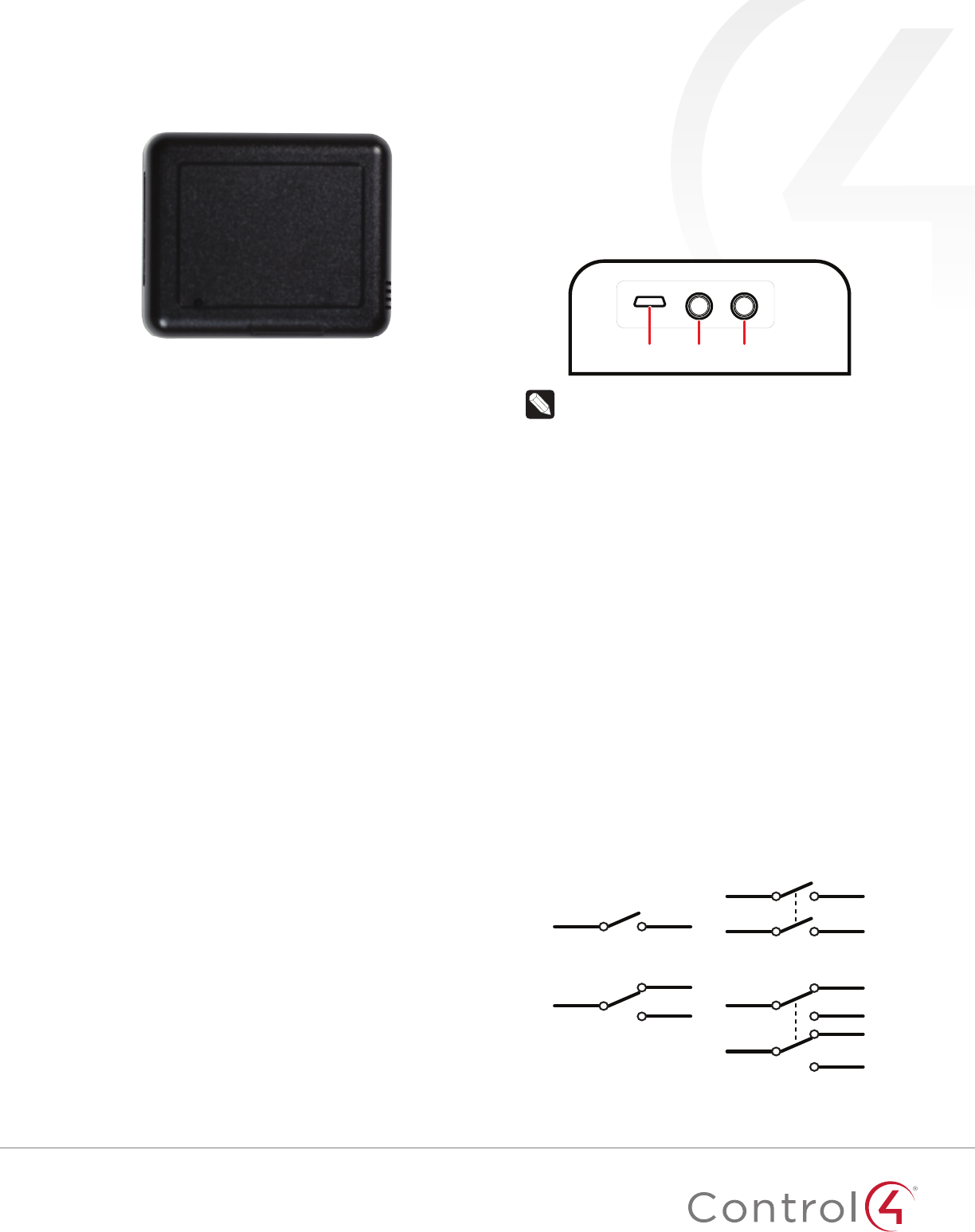
As ZigBee to IR
The two 3.5 mm IR ports allow you to connect up to two standard
IR emitters to control any IR-controlled devices, such as TVs,
DVRs, and receivers.
When connecting IR emitters, make note of which port each
emitter is connected to (labeled “1” and “2”).
IR codes sent from the controller to the ZigBee IO and Extender
are cached at the device, resulting in faster IR control response
times.
Micro USB IR 1 IR 2
Note: Y IR cables can be used, or IR cables can be
spliced together (in parallel, not in series), to increase
the number of controlled devices. Be aware that these
connected emitters cannot be controlled independently
but will all fire simultaneously from the shared IR
port. Test to verify that there is no crossover code
functionality between devices sharing the same IR port
to avoid unwanted side eects.
As a contact and relay
The device has an internal contact along one edge that can
be used to detect open or closed states when installed with
a mounted magnet. Up to four contacts (besides the internal
contact) or two additional relays, or a combination of the two,
can be used. Each option is outlined below in “Contact and Relay
Wiring Options,” and after it’s physically wired, the correct option
must be set on the Properties tab as outline further below in the
section “IO Options.”
As a relay
As a relay, this device provides wireless control of garage door
openers, window coverings, fireplaces, and pumps (along with
other relay control applications) inside or outside the home. It
integrates into Control4 systems as standard relays that can be
opened, closed, toggled, or pulsed.
The relay enables wireless control of any device controllable
by one or two low-voltage SPST relays or one simulated SPDT/
DPDT relay. These functions appear in a Control4 system as relay
outputs (relays) in Composer Pro.
SPST
(single pole single throw)
(single pole double throw)
SPDT
(double pole single throw)
DPST
(double pole double throw)
DPDT
ZigBee IO and Extender
Installation Guide
2
As a contact sensor
Depending on the selected IO configuration, up to four external
contacts are possible. As a contact sensor, this device allows
wireless monitoring of garage doors, gates, windows, mailboxes,
doorbells, and pool or spa covers (along with other contact
sensor monitoring applications you integrate or devise). These
functions appear in a Control4 system as contact sensor inputs,
which can trigger home automation events.
The internal contact is a magnetic reed switch. To use this
internal contact, the Z2IO should be mounted so that the
indention (along the same edge as the identify button) comes
in close proximity to a mounted magnet (not included) in a fully
closed state (door is closed). When the door opens, the magnetic
connection is lost, and that state change is pushed to the system.
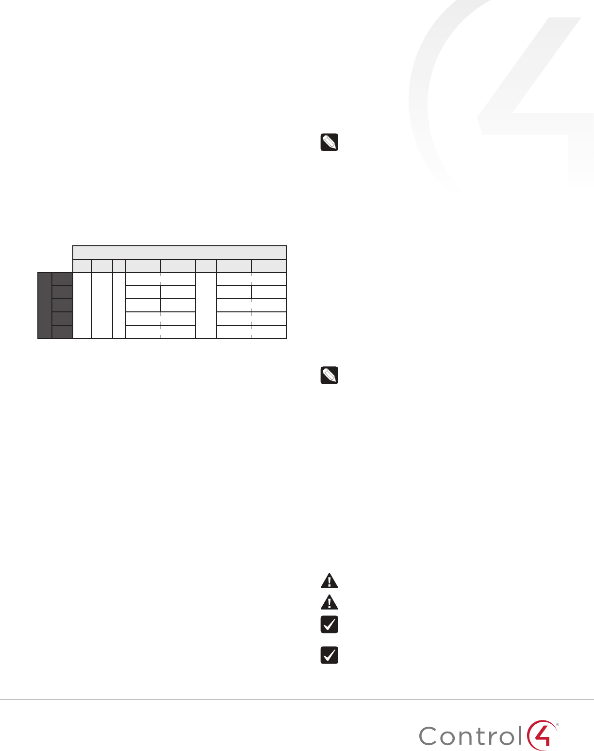
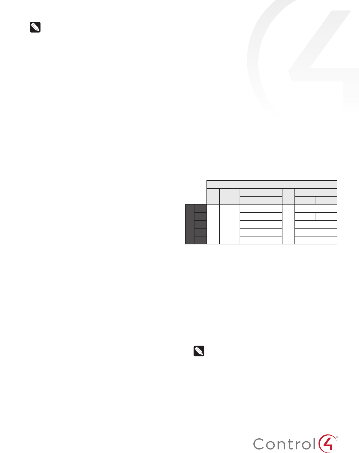
Contact and relay wiring options
There are five wiring options for contacts and relays. After they
are physically wired (as explained below), the correct option
must be manually selected on the Properties tab using the IO
Properties drop-down box.
Pins
PWR
Cm T
C4 C3 Cm C2 C1
Options
1
+ Cm T
R2
(SPST)
R2
(SPST)
Cm
R1
(SPST)
R1
(SPST)
2C4 C3 C2 C1
3C2 C1 R1
(SPST)
R1
(SPST)
4R2
(SPDT)
R2
(SPDT)
R1
(SPDT)
R1
(SPDT)
5R2
(DPST)
R2
(DPST)
R1
(DPST)
R1
(DPST)
R# = Relay, C# = Contact, Cm = Common ground (-), T = Thermistor,
SPST = Single pole single throw, SPDT = Single pole double throw,
DPST = Double pole single throw
Option 1: Two Relays using R1, R2—Two independent, single
pole single throw (SPST) relays. Each relay controls a single
circuit.
• Relay 1 is wired to pins C1 and pin C2.
• Relay 2 is wired to pins C3 and pin C4
Option 2: Four Contacts using C1, C2, C3, C4—Four
independently sensed circuits.
• Contact 1 is wired to pin C1 and pin Cm (Common).
• Contact 2 is wired to pin C2 and pin Cm (Common).
• Contact 3 is wired to pin C3 and pin Cm (Common).
• Contact 4 is wired to pin C4 and pin Cm (Common)
Option 3: One Relay (SPST) and Two Contacts using R1 and
C1, C2.
• Relay 1 is wired to pin C1 and pin C2.
• Contact 1 is wired to pin C3 and pin Cm (Common).
• Contact 2 is wired to pin C4 and pin Cm (Common).
Option 4: One Relay using R1 and R2 (SPDT)—The two relays
operate together to simulate a single SPDT (single pole
double throw) relay. However, unlike a true SPDT relay, both
relays will open during a power failure.
• Relay 1 is wired to pin C1 and pin C2.
• Relay 2 is wired to pin C3 and pin C4.
Option 5: One Relay using R1 and R2 (DPST)—The two relays
operate together to simulate a single DPST (double pole
single throw configuration) relay. However, unlike a true
DPST relay, both relays will open during a power failure.
• Relay 1 is wired to pin C1 and pin C2.
• Relay 2 is wired to pin C3 and pin C4.
As a ZigBee extender
This device acts as a ZigBee mesh extender and router. It is
designed to extend the ZigBee network into distant or hard-to-
reach areas. The Z2IO provides support for up to 32 nodes in
its ZigBee routing table. This is particularly useful in providing
ZigBee network extension to a large number of battery-operated,
non-routing ZigBee nodes. It can also be used to improve ZigBee
signal latency that can occur when ZigBee devices are installed
on the fringes of a ZigBee mesh network.
Note: Range and performance varies, depending
on variables such as location, building materials,
furnishings, and radio interference.
For optimal results, the device should be located within 50 feet
of another routing node and located in areas of the project where
the mesh may be weak or non-existent. This device should not be
placed next to a controller, inside a rack, or on a metal shelf. The
ZigBee extender functionality is always on.
As a thermistor and humidistat
The device contains an integrated thermistor and humidistat,
as well as a connection for an external thermistor, allowing it to
be used almost anywhere to report environmental conditions
or to inform the climate control system. The thermistor
senses temperatures from 32°F to 104°F (0°C to 40°C), and
the humidistat senses humidity from 5% to 90%. The device
checks the temperature and humidity every five seconds. If the
temperature has changed more than 0.5°F (0.28°C), the device
reports the new temperature. If the humidity has changed more
than 0.5%, the device reports the new humidity percentage.
Data from the integrated thermistor and humidistat is always
available, regardless of the selected IO configuration.
Notes:
• A value of -40° in the Remote Temperature field
could indicate either a negative temperature or that
no remote thermistor is connected.
• The integrated humidistat will return a zero value
after the device is rebooted until the actual humidity
value can be reported.
• To display the temperature and/or humidity in
Navigator, add the “Temperature Display Driver
(OS 2.10+)” to the project and connect the driver’s
temperature driver to the Z2IO.
• Given the variations in temperature and humidity
measurements and environments, it may be
necessary to independently test and verify the
local and remote temperature and humidity. The
properties Local Temperature Oset, Remote
Temperature Oset, and Local Humidity Oset can
be used for this purpose.
Important safety instructions
Caution! You should install this device in accordance
with all national and local electrical codes.
Caution! Improper use or installation of this device can
result in loss of and damage to property.
Important: This product is not intended for direct
connections to AC mains (120V/220V). Refer to the
specifications.
Important: You must operate this device in accordance
with the instructions and specifications in this
installation guide.
33
Important: Using this product in any manner other than
outlined in this document voids your warranty. Also,
Control4 is not responsible or otherwise liable in any
way for any damage resulting from the misuse of this
product. See
ctrl4.co/warranty
for details.
Specifications
Model number C4-Z2IO
System requirements
Control4 OS system
requirements OS version 2.10.0 or greater
Control4 system
integration
Each installed ZigBee IO and Extender adds sensor
and input connections to the Composer project.
Driver The ZigBee IO and Extender (C4-Z2IO) is available
in the Composer Online Driver Database.
Communication
Networks supported Control4 ZigBee Pro mesh networking protocol,
based on the IEEE 802.15.4 ZigBee standard
ZigBee data rate 250 kbps
ZigBee frequency
range 2.405 – 2.475 GHz
Connections
Contact sensor input 4 inputs, accepts AWG 16-28, common ground
connection.
Relay terminal ratings 0.5A @ 50V, 1A @ 24V or less
Max voltage: TBD
External thermistor 1 thermistor input, sold separately.
See “Accessories”
Infrared 2 3.5 mm IR ports
Integrated features
Internal contact Internal magnetic reed switch
Requires external magnet, sold separately
Integrated internal
thermistor
Internal thermistor can be used for local
temperature sensing: 32°F to 104°F (0°C to 40°C)
Integrated humidistat Can measure local humidity from 5% to 90%.
Power
Power consumption 100mA at 12V, fully active
External low-voltage
power supply
Micro USB power supply (included)
AC/DC 5-24V (optional)
Other
Available colors Black (water-based paintable enclosure)
Dimensions (L × W × H) 3.1” (78.7 mm) × 2.6” (65.7 mm) × 1.05” (26.6 mm)
Weight 2.5 oz. (70.9 grams)
Environmental
Temperature:
Operational 32°F to 104°F (0°C to 40°C)
Storage -20°F to 158°F (-29°C to 70°C)
Humidity 5% to 95% non-condensing
This device is not waterproof and must be kept out
of direct contact with water. The product must not
be immersed.
Paintable enclosure
The cover assembly plastics are paintable with any
water-based residential paints. Do not clog the
cover assembly vent holes with paint.
Accessories
External thermistor ZCA-EXT10A, AC-DOTS1-W, AC-PMT51-W
Installing
1 Place the device in a location which ensures the following:
• Easy access to any externally-connected wires
• ZigBee mesh networking eciency
Note: Make sure the device has good ZigBee wireless
reception by (1) ensuring it is within range of another
ZigBee device and (2) avoiding other electrical
equipment that may cause interference with the ZigBee
signal (such as cordless telephones that operate on the
2.4 GHz frequency.)
• Avoiding unnecessary exposure to extreme environmental
conditions.
IMPORTANT! Do not place the device in direct sunlight.
2 If an external thermistor is used with the device, place
it away from direct sunlight, drafts, doorways, skylights,
windows, and exterior walls for best accuracy.
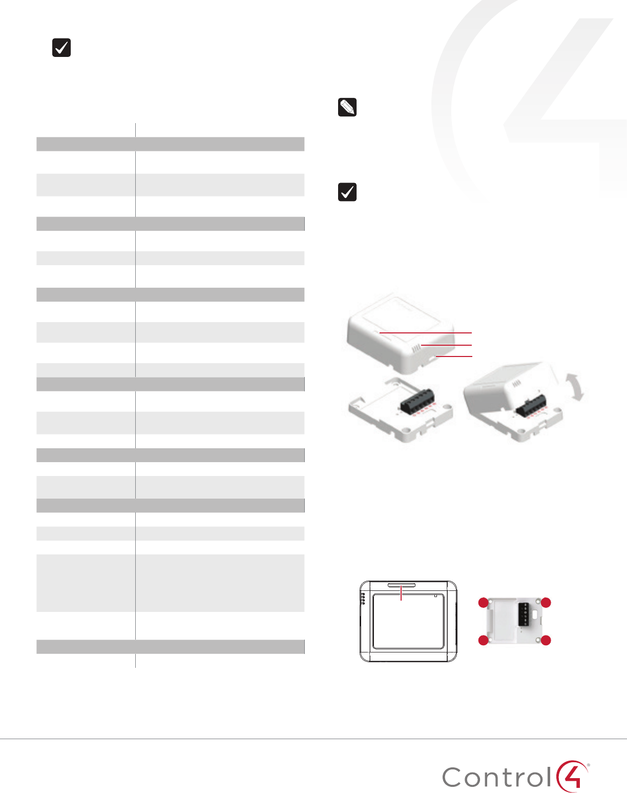
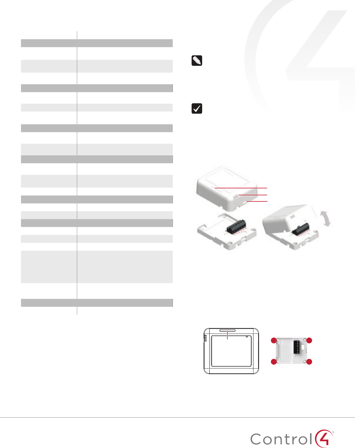
3 Detach the tray from the cover by inserting a flat screwdriver
into the opening slot in the side of the cover and pushing in
gently, while at the same time pulling the cover out and away
from the tray.
Temperature chamber/LED display
Reed switch location
Opening slot
Cover
Tray
The cover holds the radio logic board
(the actual device) and pins, the IR
ports, the internal contact, and the
USB power connector. The cover
attaches to the tray. The tray holds the
wiring terminals and is mounted to a
wall or flat surface.
The cover “rocks” into contact with
the tray. To separate the two, insert a
screwdriver or other flat object into the
opening slot on the side of the cover,
gently push in and then “rock” it away
from the tray.
4 Position the tray against the wall or other flat surface.
5 If you are using the internal contact, position the device so
that the narrow indentation that marks the internal contact
(on the long edge of the cover) aligns with the external
magnet (not included).
B
B
B
B
Indentation
6 Mark the locations of the four screw holes on the wall.
7 If mounting the device to drywall, remove the tray from the
wall and drill four 3/16-inch (4.75mm) mounting holes at the
four screw hole locations (B) previously marked on the wall.
4
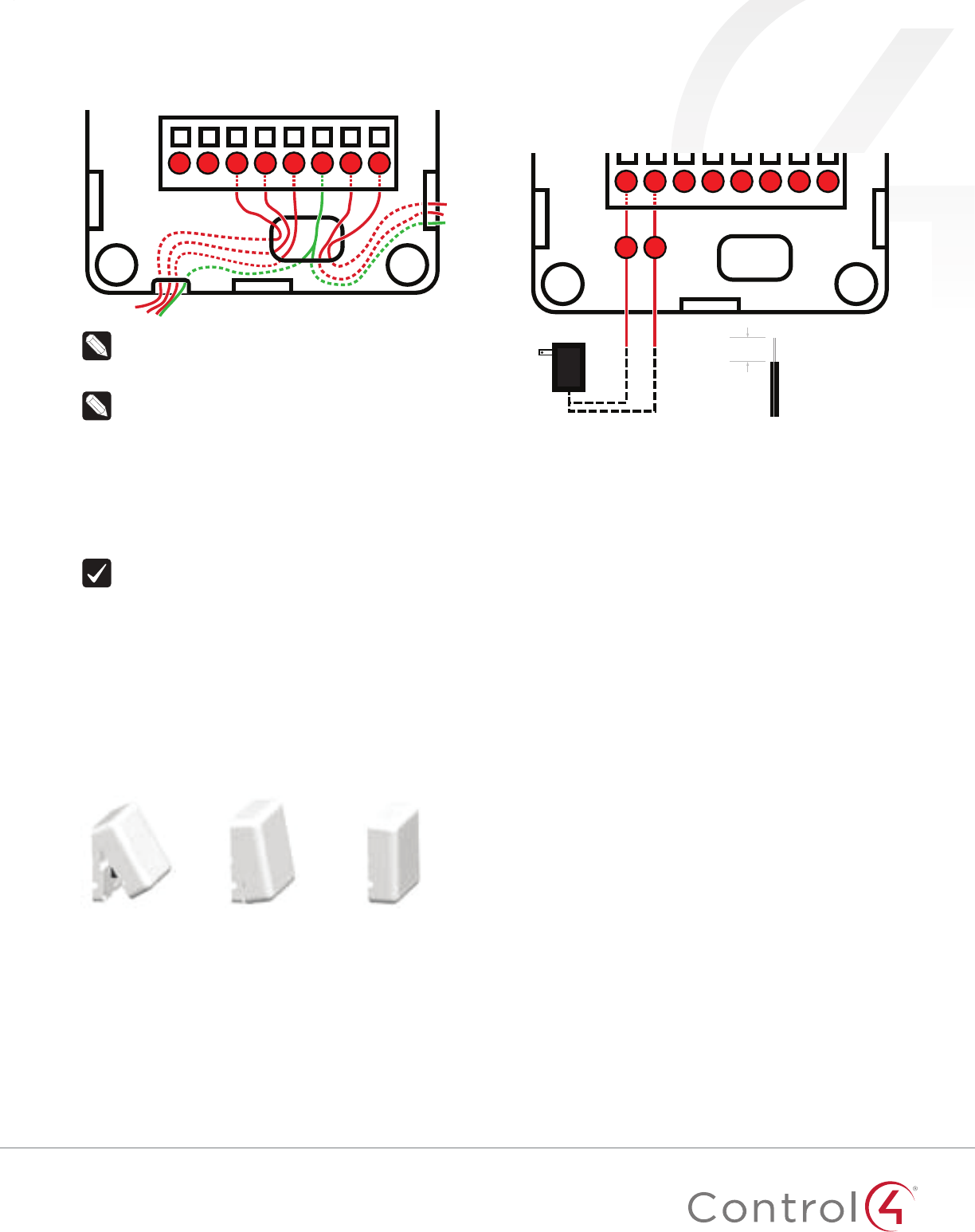
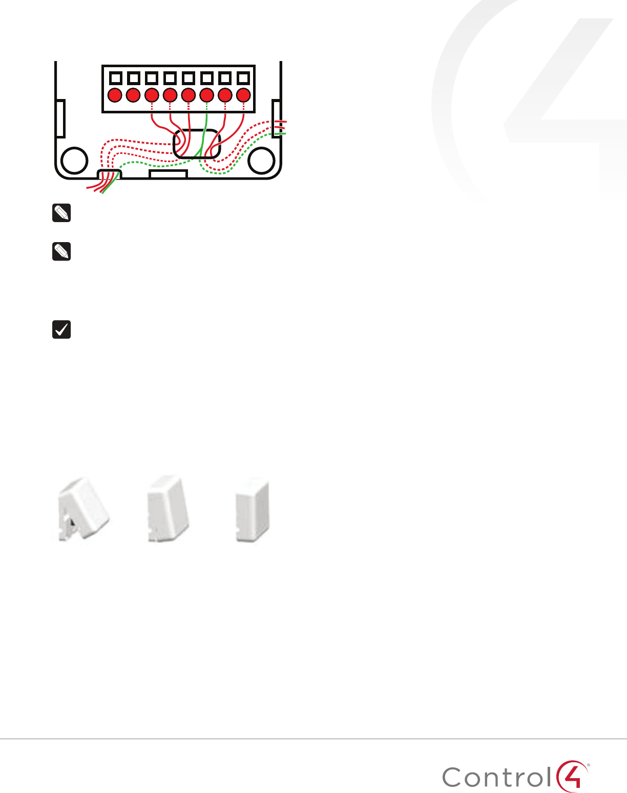
8 Thread any relay wires, contact wires, and external
thermistor wires from the wall through the openings in the
tray and to the terminal block.
T C1C2CmC3C4
PWR
Cm
Note: The two Cm (common/ground) pins are
connected and can be used interchangeably.
9 Insert and tighten the mounting screws.
Note: You may optionally choose to use robust two-
sided tape to mount the tray assembly to the wall or
other flat surface, as long as the tape won’t prevent the
back of the tray from sitting flush against the mounting
surface.
10 Connect the wires from the tray to the terminals in the cover,
matching the proper wires to the target terminal locations.
The pin/terminal definitions are defined within Composer
Pro. See “Configuring” on the next page. (Pins Cm and PWR
are used for optional external power connections.)
Important! When using multiple external contact
sensors, or when using an external contact sensor
along with an external thermistor, you MUST connect
each device to one of the Cm pins in addition to
the appropriate sensor or thermistor pin to make a
proper wiring connection. See the “Sample wiring
configurations” section of this document for examples.
11 Attach the cover assembly to the tray:
a Align the side of the cover with the side of the tray,
engaging the plastic tabs with the corresponding holes.
b Rock the cover into place, snapping it to the tray.
c Press firmly on the bottom center edge of the cover to
snap and lock it to the tray assembly.
a. Align the cover edge’s
two latching tabs with
corresponding tab
receivers on the tray’s
edge.
b. Close the cover by
rocking it toward the
other end of the tray.
c. Press firmly on the
center edge of the
cover until it snaps and
locks into place with
the tray.
12 For ZigBee to IR, connect any IR emitters to the two IR
ports, then ax the emitter head to the IR window on the
device to control (such as a TV).
Connecting alternate DC power
Although a power adapter is included, you may elect to instead
connect an alternate 5-24V DC or AC power source to pins Cm-
PWR. Connect DC positive polarity to pin PWR, and negative to
pin Cm.
T C1C2CmC3C4
PWR
Cm
DC power
3/8˝
(9.5 mm)
+ –
Configuring
Connections
Static connections
Some connections in the driver are static in that they are
always available regardless of any settings/options. These
include the two IR connections, IR Output 1 and IR Output 2,
and the internal contact.
Dynamic connections
Other connections in the driver are dynamic in that the
connections will appear based on certain options—in
particular, the IO Options property. If you change to another
IO option, any connections created in the original IO option
will be broken.
To configure your device:
1 Add the device to your Composer Pro project. When
prompted to identify the device, press the ID button on the
face of the cover four times. The green LED blinks twice to
confirm the ID has been sent to the Control4 system.
- OR -
In Composer Express, add a device into the project, scan for
ZigBee devices, then press the ID button on the face of the
cover four times.
2 In the driver’s Properties tab, view or configure the settings
explained below under “Properties,” then click Set to the
right of the setting after each change.
3 Configure each relay’s power up state. This is the state you
want the relay to adopt after a device reboot. For example,
after a power outage (resulting in a device reboot), you
may want the garage door to default to closed, the window
coverings to be restored to their last known state, and the
fireplace to be turned o.
55
Tip: Two SPST relays can optionally be linked to simulate
a single SPDT relay. However, unlike a true SPDT relay,
both relays will open during a power failure.
4 Add generic contact drivers (such as Door Contact Sensor,
Gate, and Motion Sensor) and relay drivers (such as Blinds,
Door Lock, and Pump) in System Design view, then connect
the generic driver to the appropriate connection on the C4-
Z2IO device in Connections view.
5 For programming, use these events:
• Online: Triggers when the device comes online.
• Oine: Triggers when the device goes oine.
• Reboot: Triggers when the device reboots.
Properties
General properties
• Log Level: Standard for most drivers, this property
allows you to filter which message types display in the
Lua Output window. Options 0 - 5 correspond to Fatal
through Trace levels, increasing in level of verbosity.
Options are 0=Fatal, 1=Error, 2=Warning, 3=Info, 4=Debug,
and 5=Trace. Default is 1 - Error.
• Log Mode: Activates logging of diagnostic information.
The log level is set in the above property. Options include
O, Print (to the window), Log (to the Director Log), and
Print and Log (both). Default is O.
• Driver Version: (Read only) Shows the version number of
the driver currently in use.
• Device Status: (Read only) Shows the current status of
the product, whether online or oine. However, in some
cases, the device may not report its status immediately,
such as when the device is rebooting.
• Firmware Version: (Read only) Shows the version
number of the firmware currently in use on the device.
The firmware will be updated automatically over the air
when the Control4 OS is updated and when that update
includes a new firmware version for this device.
• Bootloader Version: (Read only) Shows the version
number of the firmware currently in use on the device.
The bootloader can only be updated by Control4, so this
property is for support/diagnostic information only.
• LED Mode: Determines the behavior of the LED light on
the top/front of the product. Options include O, ZigBee
(which shows the ZigBee status; see “Identification and
Button Presses” below), and IR (which shows activity
when IR signals are sent to the IR ports). Default is O.
When the property is set to O, button presses should still
temporarily prompt the LED to show the status.
Humidity prperties
• Local Humidity: (Read only) Shows the relative humidity
measured where the device is located. The value is shown
as a percentage.
• Local Humidity Oset: The humidity sensor provides
accuracy of +/- 4% relative humidity. Adjusting the
Local Humidity Oset can result in increased inaccuracy
of relative humidity reporting without using humidity
calibration equipment for validation.
Temperature and humidity properties
• Temperature Scale: Sets which scale is used to
calculate the temperature used in the Local and Remote
Temperature properties described below, and aects only
the Properties tab’s settings. Options include Fahrenheit
and Celsius. Default is Fahrenheit.
• Local Temperature: (Read only) Shows the most recent
reported temperature recorded by the internal thermistor.
The scale of the temperature is determined by the
Temperature Scale property.
• Local Temperature Oset—Modifies the reported local
temperature to account for environmental variances. The
temperature can be changed downward or upward by a
maximum of 20 degrees. The default is 0 (no correction).
• Remote Temperature: (Read only) Shows the most recent
reported temperature recorded by the remote thermistor.
The scale of the temperature is determined by the
Temperature Scale property.
• Remote Temperature Oset—Modifies the reported
remote temperature (the temperature recorded by
an external thermistor) to account for environmental
variances. (When multiple temperature sensors are
located in the same room, you may notice each sensor
shows a slightly dierent reading. This results from normal
manufacturing variances in temperature sensors and the
device’s position/location in the room.) The temperature
can be changed downward or upward by a maximum of
20 degrees. The default is 0 (no correction).
IO properties
• IO Options: Tells the device how its eight configuration
pins are assigned. The selected option is retained even
after a system reboot or update.
Pins
PWR
Cm T
R2
Cm
R1
C4 C3 C2 C1
Options
1
+ Cm T
R2
(SPST)
R2
(SPST)
Cm
R1
(SPST)
R1
(SPST)
2C4 C3 C2 C1
3C2 C1 R1
(SPST)
R1
(SPST)
4R2
(SPDT)
R2
(SPDT)
R1
(SPDT)
R1
(SPDT)
5R2
(DPST)
R2
(DPST)
R1
(DPST)
R1
(DPST)
R# = Relay, C# = Contact, Cm = Common ground (-), T = Thermistor,
SPST = Single pole single throw, SPDT = Single pole double throw,
DPST = Double pole single throw
• Option 1: R1, R2 (both SPST [single pole single throw]):
(Default) Both relays are single pole single throw,
meaning they are independent of each other; or, in
other words, each relay controls only one circuit.
• Option 2: C1, C2, C3, C4: Four contacts.
• Option 3: R1 (SPST), C1, C2: One relay (single pole
single throw) and two contacts.
• Option 4: R1 (SPDT [single pole double throw]): The
two relays operate together to simulate a single SPDT
(single pole double throw) relay. However, unlike a true
SPDT relay, both relays will open during a power failure.
• Option 5: R1 (DPST [double pole single throw]): The
two relays operate together to simulate a single DPST
(double pole single throw configuration) relay.
Notes:
• The ZigBee extender, IR emitter control, internal
contact, internal thermistor, and internal humidistat
remain active regardless of the selected IO
configuration.
• The selected IO option will change the available
connections, so existing connections will be
disconnected or deleted.
• The selected IO option determines the available fields
in Contact properties and Relay properties.
Contact properties
6
• Contact Internal Status: (Read only) Shows the status of
the static connection for the internal contact.
• Contact 1-4 Status: (Read only) Represents the status of
the wired contacts if IO Option 1, 3, 4, or 5 is selected.
Relay properties
• Relay 1 Power Up State and Relay 2 Power Up State:
(Read only) Represents the status of the relays if IO
Option 1, 3, 4, or 5 is selected. The options are Restore
Last State, Set To OPEN, and Set To CLOSED. The default
is Restore Last State.
• Relay 1 Status and Relay 2 Status: (Read only) Represents
the status of the relays if IO Option 1, 3, 4, or 5 is selected.
Actions tab
Buttons located on the Actions tab allow you to view
version and diagnostic information and force relay actions.
(Relay actions will always be shown, regardless of the IO
configuration.)
• Version Information: This action button will display the
versions of the driver’s Base Template and Template, as
well as the Boot Loader to the Lua Output window of the
Lua tab. The Log Mode property does not have to be set
to Print to display this information to the window.
• Diagnostic Information: This action button will display the
following information to the Lua Output window of the
Lua tab (the Log Mode property does not have to be set
to Print to display this information to the window): device
ZigBee MAC address, ZigBee mesh PAN id, Template
Version, Base Template Version, Boot Loader Version,
ZigBee Node ID.
• Relay 1 Close and Relay 2 Close: These action buttons will
trigger the corresponding relay to close.
• Relay 1 Open and Relay 2 Open: These action buttons will
trigger the corresponding relay to open.
Troubleshooting
If the device is not working:
• Reboot the device by disconnecting power, then re-
connecting power.
• Check for proper wiring. See the “Wiring Configuration”
diagrams.
• Review the log in the driver’s Lua tab.
• Restore factory defaults (13 button presses).
Note: Un-identifying a device o the ZigBee mesh will cause it to
do a factory reset. A factory reset reverts all relays to the open
state, and the settings for Power Up State will revert to Restore
Last State. The settings are preserved, however, after a power
cycle or reboot.
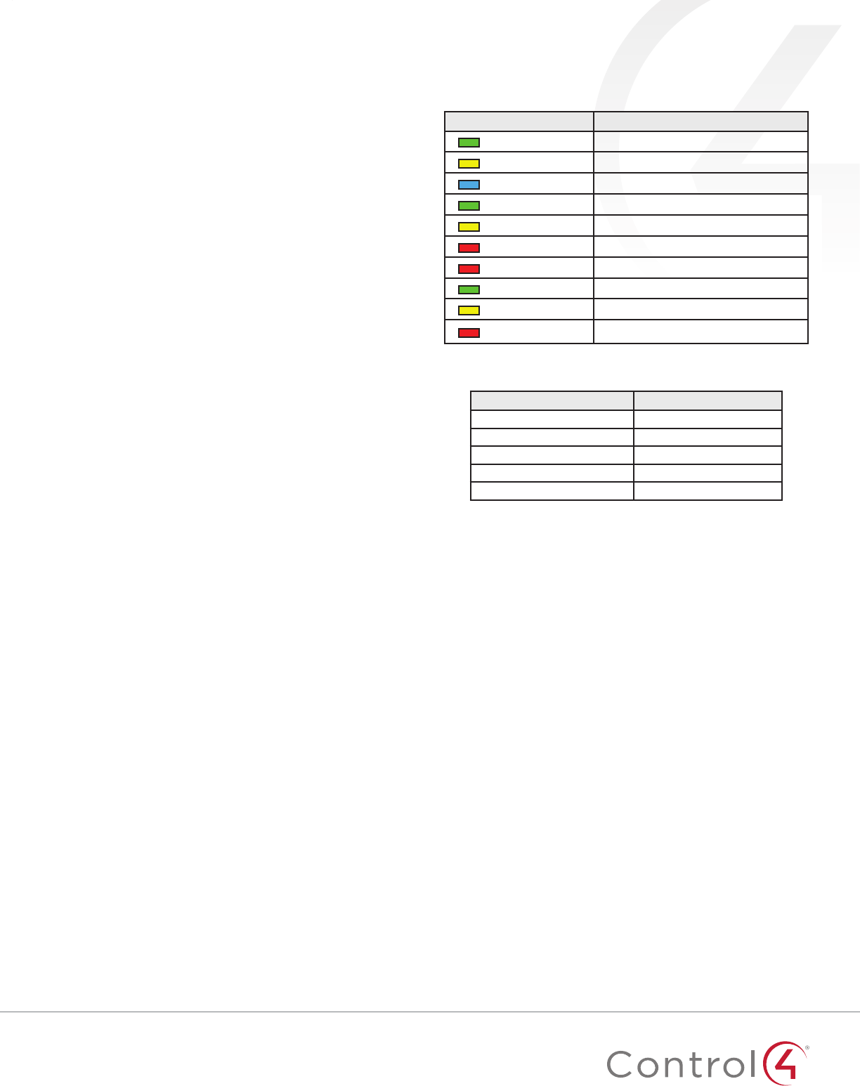
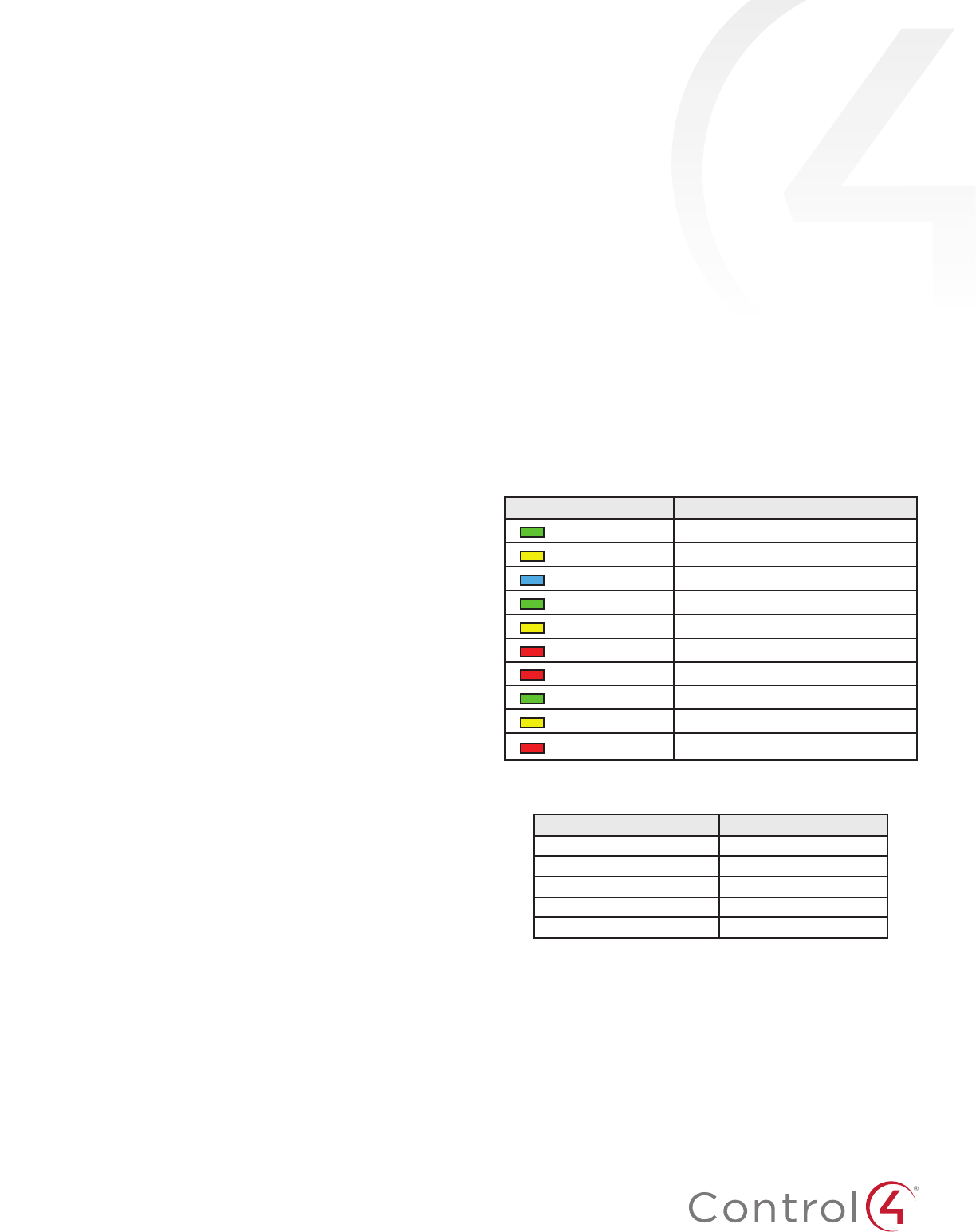
LED diagnostics
The indicated statuses appear during device identification and
when the ID button is pressed once.
LED Description
[Green] On Oine/Waiting for Director
[Yellow] Slow flashing Scanning
[Blue] On Join success
[Green] Fast flashing Join success signal strength=good
[Yellow] Fast flashing Join success signal strength=adequate
[Red] Fast flashing Join success signal strength=risk/low
[Red] Medium flashing Join failed (then returns to oine)
[Green] Slow flashing Signal strength=good (from Network Tools)
[Yellow] Slow flashing Signal strength=adequate (from Network Tools)
[Red] Slow flashing Signal strength=risk/low (from Network Tools)
Button sequences
Functions # of button presses
Identify 4
Reboot/Reset 15
Reset application defaults 9
Leave mesh, restore factory defaults 13
Signal strength flash LEDs 1
Restoring to previous firmware version
1 Power o the device (disconnect power).
2 While holding down the ID button, reconnect power, and
continue to press the ID button until the LED changes from
red to white (about five seconds).
3 Release the button. The device will reboot to its previous
firmware version in about one minute.

11
Package contents
• C4-Z2C ZigBee Contact Sensor
• Four wall mounting screws
• Four plastic dry wall anchors
• AA batteries (2)
Requirements
• Composer Pro 2.10.0 or higher
Features
The ZigBee Contact Sensor (Z2C) is a single device that
combines the features of:
• Remote contact sensors (up to four)
• Remote thermistors (one)
• Internal contact (internal magnetic reed switch)
• Internal thermistor and humidistat
Any of these inputs can be used to trigger and control automated
events—such as sending an e-mail or turning on a cabinet light
when its door is opened—throughout the Control4 system.
You can position this wireless device anywhere you need contact
connections or climate reporting.
As a contact sensor
The device contains five contacts: one internal contact and
connections for four wired contacts.
The internal contact is a magnetic reed switch. To use this internal
contact, the Z2C should be mounted so that the indention (along
the same edge as the identify button) comes in close proximity
to a mounted magnet (not included) in a fully closed state (door
is closed). When the door opens, the magnetic connection is lost,
and that state change is pushed to the system.
Wiring guide:
Contact 1 -> Pin C1
Contact 2 -> Pin C2
Contact 3 -> Pin C3
Contact 4 -> Pin C4
(All can use either of the Cm pins as Common)
As a thermistor and humidistat
The device contains an integrated thermistor and humidistat,
as well as a connection for an external thermistor, allowing it to
be used almost anywhere to report environmental conditions
or to inform the climate control system. The thermistor
senses temperatures from 32°F to 104°F (0°C to 40°C), and
the humidistat senses humidity from 5% to 90%. The device
checks the temperature and humidity every five minutes. If the
temperature has changed more than 0.9°F (0.5°C), the device
reports the new temperature and humidity values.
Notes:
• A value of -40° in the Remote Temperature field
could indicate either a negative temperature or that
no remote thermistor is connected.
• The integrated humidistat will return a zero value
after the device is rebooted until the actual humidity
value can be reported.
• See “Sample wiring configurations” below for an
example of an external thermistor connection.
• To display the temperature and/or humidity in
Navigator, add the “Temperature Display Driver
(OS 2.10+)” to the project and connect the driver’s
temperature driver to the Z2C.
• Given the variations in temperature and humidity
measurements and environments, it may be
necessary to independently test and verify the
local and remote temperature and humidity. The
properties Local Temperature Oset, Remote
Temperature Oset, and Local Humidity Oset can
be used for this purpose.
Important safety instructions
Caution! You should install this device in accordance
with all national and local electrical codes.
Caution! Improper use or installation of this device can
result in loss of and damage to property.
Important: This product is not intended for direct
connections to AC mains (120V/220V). Refer to the
specifications.
Important: You must operate this device in accordance
with the instructions and specifications in this
installation guide.
Important: Using this product in any manner other than
outlined in this document voids your warranty. Also,
Control4 is not responsible or otherwise liable in any
way for any damage resulting from the misuse of this
product. See
ctrl4.co/warranty
for details.
ZigBee Contact Sensor
Installation Guide
2
Specifications
Model number C4-Z2C
System requirements
Control4 OS system
requirements OS version 2.10.0 or greater
Control4 system
integration
Each installed ZigBee Contact Sensor requires
input connections to the Composer project.
Driver The ZigBee Contact Sensor (C4-Z2C) is available in
the Composer Online Driver Database.
Communication
Networks supported Control4 ZigBee Pro mesh networking protocol,
based on the IEEE 802.15.4 ZigBee standard
ZigBee data rate 250 kbps
ZigBee frequency
range 2.405 – 2.475 GHz
Connections
Contact sensor input 4 inputs, accepts AWG 16-28, common ground
connection.
External thermistor 1 thermistor input, sold separately.
See “Accessories”
Integrated features
Internal contact Internal magnetic reed switch
Requires external magnet, sold separately
Integrated internal
thermistor
Internal thermistor can be used for local
temperature sensing: 32°F to 104°F (0°C to 40°C)
Integrated humidistat Can measure local humidity from 5% to 90%.
Power
Power consumption 100mA at 3V, fully active
Power AA batteries (2), included
Other
Available colors Black (water-based paintable enclosure)
Dimensions (L × W × H) 3.1” (78.7 mm) × 2.6” (65.7 mm) × 1.05” (26.6 mm)
Weight 2.5 oz. (70.9 g) without batteries
Environmental
Temperature:
Operational 32°F to 104°F (0°C to 40°C)
Storage -20°F to 158°F (-29°C to 70°C)
Humidity 5% to 95% non-condensing
This device is not waterproof and must be kept out
of direct contact with water. The product must not
be immersed.
Paintable enclosure
The cover assembly plastics are paintable with any
water-based residential paints. Do not clog the
cover assembly vent holes with paint.
Accessories
External thermistor ZCA-EXT10A, AC-DOTS1-W, AC-PMT51-W
Installing
1 Place the device in a location which ensures the following:
• Easy access to any externally-connected wires
• ZigBee mesh networking eciency
Note: Make sure the device has good ZigBee wireless
reception by (1) ensuring it is within range of another
ZigBee device and (2) avoiding other electrical
equipment that may cause interference with the ZigBee
signal (such as cordless telephones that operate on the
2.4 GHz frequency.)
• Avoiding unnecessary exposure to extreme environmental
conditions.
IMPORTANT! Do not place the device in direct sunlight.
2 If an external thermistor is used with the device, place
it away from direct sunlight, drafts, doorways, skylights,
windows, and exterior walls for best accuracy.
3 Detach the tray from the cover by inserting a flat screwdriver
into the opening slot in the side of the cover and pushing
in gently, while at the same time pulling the cover out and
away from the tray.
Temperature chamber/LED display
Internal contact location
Opening slot
Cover
Tray
The cover holds the radio logic board
(the actual device) and pins and the
internal contact. The cover attaches
to the tray. The tray holds the wiring
terminals and is mounted to a wall or
flat surface.
The cover “rocks” into contact with
the tray. To separate the two, insert a
screwdriver or other flat object into the
opening slot on the side of the cover,
gently push in and then “rock” it away
from the tray.
4 Position the tray against the wall or other flat surface.
5 If you are using the internal contact, position the device so
that the narrow indentation that marks the internal contact
(on the long edge of the cover) aligns with the external
magnet (not included).
B
B
B
B
Indentation
6 Mark the locations of the four screw holes on the wall.
7 If mounting the device to drywall, remove the tray from the
wall and drill four 3/16-inch (4.75mm) mounting holes at the
four screw hole locations (B) previously marked on the wall.
33
8 Thread any contact or thermistor wires from the wall through
the openings in the tray and to the terminal block.
T C1C2CmC3C4VO Cm
Note: The two Cm (common/ground) pins are
connected and can be used interchangeably.
9 Insert and tighten the mounting screws.
Note: You may optionally choose to use robust two-
sided tape to mount the tray assembly to the wall or
other flat surface, as long as the tape won’t prevent the
back of the tray from sitting flush against the mounting
surface.
10 Connect the wires from the tray to the terminals in the cover,
matching the proper wires to the target terminal locations.
Important! When using multiple external contact
sensors, or when using an external contact sensor along
with an external thermistor, you must connect each
device to one of the Common (Cm) pins in addition
to the appropriate sensor or thermistor pin to make
a proper wiring connection. See the “Sample wiring
configurations” section of this document for examples.
11 Attach the cover assembly to the tray:
a Align the side of the cover with the side of the tray,
engaging the plastic tabs with the corresponding holes.
b Rock the cover into place, snapping it to the tray.
c Press firmly on the bottom center edge of the cover to
snap and lock it to the tray assembly.
a. Align the cover edge’s
two latching tabs with
corresponding tab
receivers on the tray’s
edge.
b. Close the cover by
rocking it toward the
other end of the tray.
c. Press firmly on the
center edge of the
cover until it snaps and
locks into place with
the tray.
Configuring
To configure your device:
1 Add the device to your Composer Pro project. When
prompted to identify the device, press the ID button on the
face of the cover four times. The green LED blinks twice to
confirm the ID has been sent to the Control4 system.
- OR -
In Composer Express, add a device into the project, scan for
ZigBee devices, then press the ID button on the face of the
cover four times.
2 In the driver’s Properties tab, view or configure the settings
explained below under “Properties,” then click Set to the
right of the setting after each change.
3 Add generic contact drivers (such as Door Contact Sensor,
Gate, and Motion Sensor) in System Design view, then
connect the generic driver to the appropriate connection on
the C4-Z2C device in Connections view.
4 For programming, use these events:
• Missed Checkin: Triggers when the device misses a
controller check in for the number of times specified in
the driver’s “Missed Checkin Limit” setting.
• Online: Triggers when the device comes online.
• Oine: Triggers when the device goes oine.
• Reboot: Triggers when the device reboots.
Properties
General properties
• Log Level: Standard for most drivers, this property
allows you to filter which message types display in the
Lua Output window. Options 0 - 5 correspond to Fatal
through Trace levels, increasing in level of verbosity.
Options are 0=Fatal, 1=Error, 2=Warning, 3=Info, 4=Debug,
and 5=Trace. Default is 1 - Error.
• Log Mode: Activates logging of diagnostic information.
The log level is set in the above property. Options include
O, Print (to the window), Log (to the Director Log), and
Print and Log (both). Default is O.
• Driver Version: (Read only) Shows the version number of
the driver currently in use.
• Device Status: (Read only) Shows the current status of
the product, whether online or oine. However, in some
cases, the device may not report its status immediately,
such as when the device is rebooting.
• Firmware Version: (Read only) Shows the version
number of the firmware currently in use on the device.
The firmware will be updated automatically over the air
when the Control4 OS is updated and when that update
includes a new firmware version for this device.
• Bootloader Version: (Read only) Shows the version
number of the firmware currently in use on the device.
The bootloader can only be updated by Control4, so this
property is for support/diagnostic information only.
Battery properties
• Battery Level: Reports the charge level of the battery.
When the batteries on a Z2C are low, a low battery alert
can be configured using the Z2C’s battery level. When the
batteries are very low, the LED behavior and temperature
and humidity reporting become unreliable.
Humidity properties
• Local Humidity: (Read only) Shows the relative humidity
measured where the device is located. The value is shown
as a percentage.
• Local Humidity Oset: The humidity sensor provides
accuracy of +/- 4% relative humidity. Adjusting the
Local Humidity Oset can result in increased inaccuracy
of relative humidity reporting without using humidity
calibration equipment for validation.
4
Temperature properties
• Temperature Scale: Sets which scale is used to
calculate the temperature used in the Local and Remote
Temperature properties described below, and aects only
the Properties tab’s settings. Options include Fahrenheit
and Celsius. Default is Fahrenheit.
• Local Temperature: (Read only) Shows the most recent
reported temperature recorded by the internal thermistor.
The scale of the temperature is determined by the
Temperature Scale property.
• Local Temperature Oset—Modifies the reported local
temperature to account for environmental variances. The
temperature can be changed downward or upward by a
maximum of 20 degrees. The default is 0 (no correction).
• Remote Temperature: (Read only) Shows the most recent
reported temperature recorded by the remote thermistor.
The scale of the temperature is determined by the
Temperature Scale property.
• Remote Temperature Oset—Modifies the reported
remote temperature (the temperature recorded by
an external thermistor) to account for environmental
variances. (When multiple temperature sensors are
located in the same room, you may notice each sensor
shows a slightly dierent reading. This results from normal
manufacturing variances in temperature sensors and the
device’s position/location in the room.) The temperature
can be changed downward or upward by a maximum of
20 degrees. The default is 0 (no correction).
Contacts properties
• Contact Internal Status: (Read only) Shows the status of
the static connection for the internal contact.
• Contact 1-4 Status: (Read only) Represents the status of
the wired contacts.
Checkin properties
• Checkin Interval: Defines how often the device checks
with the controller to see if the controller is requesting
information from the device, such as version information,
or if the controller is trying to update any settings on
the device, such as the check in interval. A check in can
also be manually triggered by pressing the button on the
Z2C. The check-in interval can be configured to check in
with the controller between 10 minutes and 4 hours. The
default is 10 minutes. Increasing the check-in interval will
increase the battery life of the device.
• Last Checkin Time: (Read only) Shows the most recent
time the device checked in with the controller.
• Missed Checkin Limit: Sets the number of times the
checkin is missed before triggering the “Missed Checkin”
programming event.
Actions tab
Buttons located on the Actions tab allow you to view version
and diagnostic information.
• Version Information: This action button will display the
versions of the driver’s Base Template and Template, as
well as the Boot Loader to the Lua Output window of the
Lua tab. The Log Mode property does not have to be set
to Print to display this information to the window.
• Diagnostic Information: This action button will display the
following information to the Lua Output window of the
Lua tab (the Log Mode property does not have to be set
to Print to display this information to the window): device
ZigBee MAC address, ZigBee mesh PAN id, Template
Version, Base Template Version, Boot Loader Version,
ZigBee Node ID.
Troubleshooting
If the device is not working:
• Reboot the device by disconnecting power, then re-
connecting power.
• Check for proper wiring. See the “Wiring Configuration”
diagrams.
• Review the log in the driver’s Lua tab.
• Restore factory defaults (13 button presses).
Note: Un-identifying a device o the ZigBee mesh will cause it
to do a factory reset. The settings are preserved, however, after a
power cycle or reboot.
LED diagnostics
The indicated statuses appear during device identification and
when the ID button is pressed once.
LED Description
[Green] On Oine/Waiting for Director
[Yellow] Slow flashing Scanning
[Blue] On Join success
[Green] Fast flashing Join success signal strength=good
[Yellow] Fast flashing Join success signal strength=adequate
[Red] Fast flashing Join success signal strength=risk/low
[Red] Medium flashing Join failed (then returns to oine)
[Green] Slow flashing Signal strength=good (from Network Tools)
[Yellow] Slow flashing Signal strength=adequate (from Network Tools)
[Red] Slow flashing Signal strength=risk/low (from Network Tools)
Button sequences
Functions # of button presses
Identify 4
Reboot/Reset 15
Reset application defaults 9
Leave mesh, restore factory defaults 13
Signal strength flash LEDs 1
Restoring to previous firmware version
1 Power o the device (disconnect power).
2 While holding down the ID button, reconnect power, and
continue to press the ID button until the LED changes from
red to white (about five seconds).
3 Release the button. The device will reboot to its previous
firmware version in about one minute.
55
Sample wiring configuration
16-28 AWG
from
equipment
C1C2C3C4
3/8˝
(9.5 mm)
Thermistor
Common
T C1C2CmC3C4VO Cm
Additional resources
The following resources are available for additional support:
• Control4 Knowledgebase and forums
• Control4 Technical Support
• Control4 website:
www.control4.com
• Composer documentation available at
ctrl4.co/docs
.
For the latest version of this document, open this URL or scan the
QR code on a device that can view PDFs.
DATA SHEET
ctrl4.co/z2c-ds
MOST RECENT VERSION
ctrl4.co/z2c-ig
Regulatory/Safety information
To review Regulatory information for your particular Control4
products, see the information located on the Control4 website at
ctrl4.co/reg
.
Patent information
Applicable patents are available at
ctrl4.co/patents
.
Warranty
Visit
ctrl4.co/warranty
for details.
Copyright ©2017, Control4 Corporation. All rights reserved. Control4, the Control4 logo, the 4-ball logo, 4Store, 4Sight, Control4 My Home, and Mockupancy are
registered trademarks or trademarks of Control4 Corporation or its subsidiaries in the United States and/or other countries. All other names and brands may be claimed
as the property of their respec-tive owners. All specifications subject to change without notice. . A
DOC-00184-A
2017-07-18 MS
7
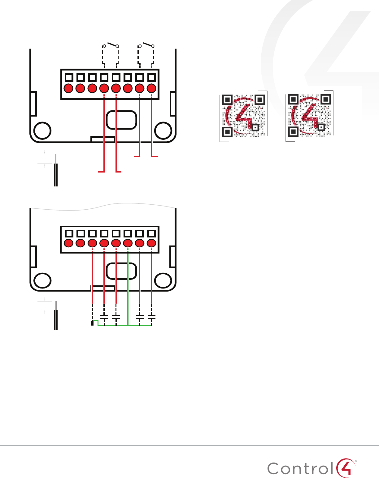
Sample wiring configurations
Option 1: R1, R2 (both SPST)
16-28 AWG
from equipment
Relay 2 (SPST)
Source1Load1
Source2Load2
Relay 1 (SPST)
3/8˝
(9.5 mm)
T C1C2CmC3C4
PWR
Cm
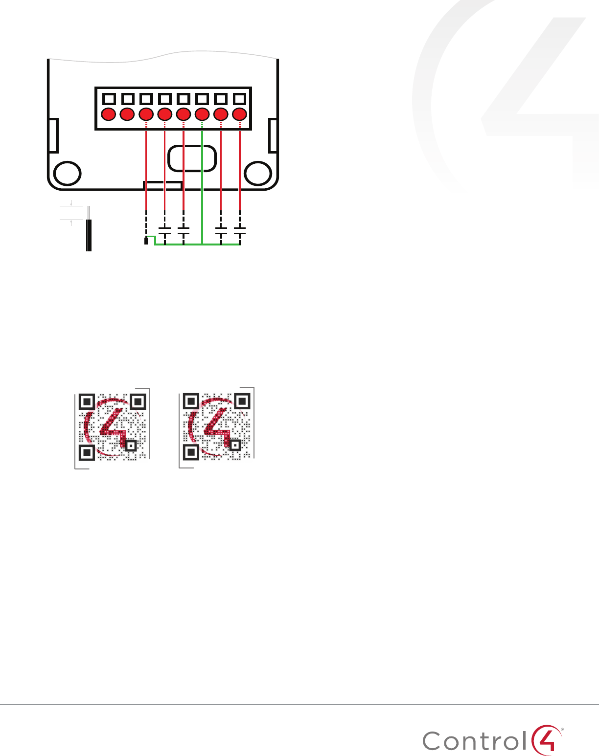
Option 2: C1, C2, C3, C4 (including an optional external thermistor)
16-28 AWG
from
equipment
C1C2C3C4
3/8˝
(9.5 mm)
Thermistor
Common
T C1C2CmC3C4
PWR
Cm
Additional resources
The following resources are available for additional support:
• Control4 Knowledgebase and forums
• Control4 Technical Support
• Control4 website:
www.control4.com
• Composer documentation available at
ctrl4.co/docs
.
For the latest version of this document, open this URL or scan
the QR code on a device that can view PDFs.
DATA SHEET
ctrl4.co/z2io-ds
MOST RECENT VERSION
ctrl4.co/z2io-ig
Regulatory/Safety information
To review Regulatory information for your particular Control4
products, see the information located on the Control4 website at
ctrl4.co/reg
.
Patent information
Applicable patents are available at
ctrl4.co/patents
.
Warranty
Visit
ctrl4.co/warranty
for details.
DOC-00184-A
2017-07-18 MS
Copyright ©2017, Control4 Corporation. All rights reserved. Control4, the Control4 logo, the 4-ball logo, 4Store, 4Sight, Control4 My Home, and Mockupancy are
registered trademarks or trademarks of Control4 Corporation or its subsidiaries in the United States and/or other countries. All other names and brands may be claimed
as the property of their respec-tive owners. All specifications subject to change without notice. . A

Regulatory Compliance & Safety Information for Control4 Model C4-Z2IO & C4-Z2C
Electrical Safety Advisory
Sécurité électrique consultatif
Important Safety Instructions
Consignes de sécurité importantes
Read the safety instructions before using this product.
Lisez les consignes de sécurité avant d'utiliser ce produit.
1. Read these instructions.
1. Lisez ces instructions.
2. Keep these instructions.
2. Conservez ces instructions.
3. Heed all warnings.
3. Respectez tous les avertissements.
4. Follow all instructions.
4. Suivez toutes les instructions.
5. Do not use this apparatus near water.
5. Ne pas utiliser cet appareil près de l'eau.
6. Clean only with dry cloth.
6. Nettoyez-le uniquement avec un chiffon sec.
7. Do not block any ventilation openings. Install in accordance with the manufacturer’s
instructions.
7. Ne pas bloquer les ouvertures de ventilation. Installer conformément aux instructions du
fabricant.
8. Do not install near any heat sources such as radiators, heat registers, stoves, or other
apparatus (including amplifiers) that produce heat.
8. Ne pas installer près de sources de chaleur telles que des radiateurs, registres de
chaleur, poêles, ou autres appareils (incluant les amplificateurs) qui produisent de la
chaleur.
9. Do not defeat the safety purpose of the polarized or grounding-type plug. A polarized
plug has two blades with one wider than the other. A grounding type plug has two blades
and a third grounding prong. The wide blade or the third prong is provided for your safety.
If the provided plug does not fit into your outlet, consult an electrician for replacement of
the obsolete outlet.
9. Ne pas contourner le dispositif de sécurité de la fiche polarisée ou de mise à la terre. Une
fiche polarisée possède deux lames dont une plus large que l'autre. Une fiche de terre a
deux lames et une troisième broche de terre. La lame large ou la troisième broche est

fournie pour votre sécurité. Si la fiche fournie ne s'adapte pas à votre prise, consultez un
électricien pour le remplacement de la prise obsolète.
10. Protect the power cord from being walked on or pinched particularly at plugs,
convenience receptacles, and the point where they exit from the apparatus.
10. Protégez le cordon d'alimentation ne soit piétiné ou pincé, en particulier au niveau des
fiches, des prises et au point où il sort de l'appareil.
11. Only use attachments/accessories specified by the manufacturer.
11. Utilisez uniquement des fixations / accessoires spécifiés par le fabricant.
12. Use only with the cart, stand, tripod, bracket, or table specified by the manufacturer, or
sold with the apparatus. When a cart is used, use caution when moving the
cart/apparatus combination to avoid injury from tip-over.
12. Utilisez uniquement avec le chariot, le socle, le trépied, le support ou la table spécifiés
par le fabricant ou vendu avec l'appareil. Lorsque vous utilisez un chariot, soyez prudent
lorsque vous déplacez l'ensemble chariot / appareil pour éviter des blessures dues au
renversement.
13. Unplug this apparatus during lightning storms or when unused for long periods of time.
13. Débranchez cet appareil pendant les orages ou lorsqu'il n'est pas utilisé pendant de
longues périodes de temps.
14. Refer all servicing to qualified service personnel. Servicing is required when the
apparatus has been damaged in any way, such as power-supply cord or plug is
damaged, liquid has been spilled or objects have fallen into the apparatus, the apparatus
has been exposed to rain or moisture, does not operate normally, or has been dropped.
14. Confiez toutes les réparations à un personnel qualifié. Une réparation est nécessaire
lorsque l'appareil a été endommagé de quelque façon que ce soit le cordon
d'alimentation ou la fiche est endommagé, du liquide a été renversé ou si des objets sont
tombés dans l'appareil, l'appareil a été exposé à la pluie ou à l'humidité, ne fonctionne
pas normalement, ou s'il est tombé.
15. This equipment uses AC power which can be subjected to electrical surges, typically
lightning transients which are very destructive to customer terminal equipment connected
to AC power sources. The warranty for this equipment does not cover damage caused
by electrical surge or lightning transients. To reduce the risk of this equipment becoming
damaged it is suggested that the customer consider installing a surge arrestor.
15. Cet équipement utilise la puissance AC qui peuvent être soumis à des surtensions
électriques, la foudre généralement transitoires qui sont très destructives envers les
équipements terminaux connectés à des sources d'alimentation CA. La garantie de cet
appareil ne couvre pas les dommages causés par les surtensions électriques ou
transitoires de foudre. Pour réduire le risque de cet équipement devient endommagé, il
est suggéré que le client envisager l'installation d'un limiteur de surtension.
16. To completely disconnect unit power from the AC mains, remove the power cord from the
appliance coupler and/or turn off the circuit breaker. To reconnect power, turn on the

circuit breaker following all safety instructions and guidelines. The circuit breaker shall
remain readily accessible.
16. Pour débrancher complètement l'alimentation secteur du réseau secteur, retirez le cordon
d'alimentation du coupleur de l'appareil et / ou éteignez le disjoncteur. Pour reconnecter
l'alimentation, allumez le disjoncteur en suivant toutes les consignes et consignes de
sécurité. Le disjoncteur doit être facilement accessible.
17. This product relies on the buildings installation for short-circuit (overcurrent) protection.
Ensure that the protective device is rated not greater than: 20A.
17. Ce produit repose sur l'installation des bâtiments pour les courts-circuits (surintensité) de
protection. Assurez-vous que le dispositif de protection est assignée ne dépassant pas:
20A.
18. Never push objects of any kind into this product through cabinet slots as they may touch
dangerous voltage points or short out parts that could result in fire or electric shock.
18. N'introduisez jamais d'objets d'aucune sorte dans ce produit à travers les fentes du
boîtier car ils pourraient toucher des points de tension dangereux ou court-circuiter des
pièces qui pourraient entraîner un incendie ou un choc électrique.
19. This product can interfere with electrical equipment such as tape recorders, TV sets,
radios, computers and microwave ovens if placed in close proximity.
19. Ce produit peut interférer avec des appareils électriques tels que les magnétophones,
téléviseurs, radios, ordinateurs et fours à micro-ondes si placés à proximité.
The lightning flash and arrow head within the triangle is a warning sign alerting
you of dangerous voltage inside the product
L'éclair et la flèche dans le triangle est un signe d'alerte pour vous avertir d'une
tension dangereuse à l'intérieur du produit
Caution: To reduce the risk of electric shock, do not remove cover (or back). No
user serviceable parts inside. Refer servicing to qualified service personnel.
Attention: Pour réduire le risque de choc électrique, ne pas retirer le couvercle
(ou l'arrière). Aucune pièce réparable par l'utilisateur. Confiez l'entretien à un
personnel qualifié.
The exclamation point within the triangle is a warning sign alerting you of
important instructions accompanying the product.
Le point d'exclamation dans un triangle est un signe d'avertissement vous
signale des instructions importantes accompagnant le produit.
See marking on bottom / back of product
Voir le marquage sur les bas / dos du produit
Warning!: To reduce the risk of electrical shock, do not expose this
apparatus to rain or moisture
AVERTISSEMENT! Pour réduire le risque de choc électrique,
n'exposez pas cet appareil à la pluie ou à l'humidité.
Save these instructions
Conservez ces instructions

Compliance of this equipment is confirmed by the following logo that is placed on the product ID
label that is placed on the bottom of the equipment:
La conformité de cet équipement est confirmée par le logo suivant qui est placé sur l'étiquette
d'identification du produit qui est placé au bas de l'équipement:
USA & Canada Compliance
FCC Part 15, Subpart B Unintentional Emissions Interference Statement
This equipment has been tested and found to comply with the limits for a Class B digital device,
pursuant to Part 15 of the FCC rules. These limits are designed to provide reasonable protection
against harmful interference when the equipment is operated in a residential installation. This
equipment generates uses and can radiate radio frequency energy and, if not installed and used
in accordance with the instructions, may cause harmful interference to radio communications.
However, there is no guarantee that interference will not occur in a particular installation. If this
equipment does cause harmful interference to radio or television reception, which can be
determined by turning the equipment off and on, the user is encouraged to try to correct the
interference by one or more of the following measures:
• Reorient or relocate the receiving antenna.
• Increase the separation between the equipment and receiver.
• Connect the equipment into an outlet on a circuit different from that to which the receiver
is connected.
• Consult the dealer or an experienced radio/TV technician for help.
FCC Partie 15, sous-section B Unintentional Déclaration sur les interférences des
émissions
Cet équipement a été testé et jugé conforme aux limites établies pour un dispositif numérique de
classe B, conformément à la Partie 15 des règlements de la FCC. Ces limites sont conçues pour
fournir une protection raisonnable contre les interférences nuisibles lorsque l'équipement est
utilisé dans une installation résidentielle. Cet équipement génère, utilise et peut émettre de
l'énergie rayonnent fréquence et, s'il n'est pas installé et utilisé conformément aux instructions, il
peut causer des interférences nuisibles aux communications radio. Cependant, il n'existe aucune
garantie que des interférences ne se produiront pas dans une installation particulière. Si cet
équipement provoque des interférences nuisibles à la réception radio ou télévision, ce qui peut
être déterminé en mettant l'équipement hors et sous tension, l'utilisateur est encouragé à essayer
de corriger l'interférence par une ou plusieurs des mesures suivantes:
• Réorienter ou déplacer l'antenne de réception.
• Augmenter la distance entre l'équipement et le récepteur.
• Connecter l'équipement à une prise sur un circuit différent de celui sur lequel le récepteur
est branché.
• Consulter le revendeur ou un technicien radio / télévision qualifié pour obtenir de l'aide.

This device complies with part 15 of the FCC rules and Industry Canada’s licence-exempt RSSs.
Operation is subject to the following two conditions: (1) This device may not cause harmful
interference, and (2) this device must accept any interference received, including interference that
may cause undesired operation.
Le présent appareil est conforme aux CNR d’Industrie Canada applicables aux appareils radio
exempts de licence. L'exploitation est autorisée aux deux conditions suivantes : (1) l'appareil ne
doit pas produire de brouillage, et (2) l'utilisateur de l'appareil doit accepter tout brouillage
radioélectrique subi, même si le brouillage est susceptible d'en compromettre le fonctionnement.
IMPORTANT! Any changes or modifications not expressly approved by the party responsible for
compliance could void the user’s authority to operate this equipment.
IMPORTANT! Tous les changements ou modifications pas expressément approuvés par la partie
responsable de la conformité ont pu vider l’autorité de l’utilisateur pour actionner cet équipement.
FCC Part 15, Subpart C / RSS-247 Intentional Emissions Interference Statement
Compliance of this equipment is confirmed by the following certification numbers that are placed
on the equipment:
Notice: The term “FCC ID:” and “IC:” before the certification number signifies that FCC and
Industry Canada technical specifications were met.
FCC ID: R33C4Z2IO
IC: 7848A-C4Z2C
This equipment must be installed by qualified professionals or contractors in accordance with
FCC Part 15.203 & IC RSS-247, Antenna Requirements. Do not use any antenna other than the
one provided with the unit.
FCC Partie 15, sous-partie C / RSS-247 Déclaration volontaire des émissions interférences
Conformité de cet appareil est confirmé par les chiffres de certification suivants qui sont placés
sur l'équipement:
Avis: Le terme «FCC ID:" et "IC:" devant le numéro de certification signifie que les spécifications
techniques de la FCC et d'Industrie Canada ont été respectées.
FCC ID: R33C4Z2IO
IC: 7848A-C4Z2IO
Cet équipement doit être installé par des professionnels qualifiés ou entrepreneurs conformément
aux normes FCC partie 15.203 & IC RSS-247, Exigences d'antenne. Ne pas utiliser une antenne
autre que celui fourni avec l'appareil.
RF Radiation Exposure Statement
This equipment complies with the FCC/IC radiation exposure limits set fourth for portable
transmitting devices operation in an uncontrolled environment. End users must follow the specific
operating instructions to satisfy RF exposure compliance.
• The equipment should only be used or installed at locations where there is normally
greater than a 20cm separation between the antenna and all persons.
• This transmitter must not be co-located or operation in conjunction with any other
antenna or transmitter.

• Any changes or modifications not expressly approved by the party responsible for
compliance could void the user’s authority to operate this equipment.
Déclaration d'exposition aux radiations RF
Cet équipement est conforme aux limites FCC / IC d'exposition aux rayonnements définies
quatrième opération appareils portables transmettre dans un environnement non contrôlé. Les
utilisateurs finaux doivent suivre les instructions de fonctionnement spécifiques pour satisfaire la
conformité aux expositions RF.
• L'équipement ne doit être utilisé ou installé à des endroits où il est normalement
supérieure à une séparation de 20 cm entre l'antenne et toute personne.
• Cet émetteur ne doit pas être co-localisés ou fonctionnement en conjonction avec une
autre antenne ou un autre émetteur.
• Tout changement ou modification non expressément approuvé par la partie responsable
de la conformité pourraient annuler l'autorité de l'utilisateur à utiliser cet équipement.

European Compliance (English)
Conformity of the equipment with the guidelines below is attested by the application of the CE
mark.
CE Declaration of Conformity
Manufacturer’s Name: CONTROL4 CORPORATION
Manufacturer’s Address: 11734 S. ELECTION ROAD SUITE 200
SALT LAKE CITY
UT 84020 USA
EU Representative Name: CONTROL4 EMEA LIMITED
EU Representative Address: UNIT3, GREEN PARK BUSINESS CENTRE
SULTON-ON-THE FOREST
YORK YO61 IET, UNITED KINGDOM
Product Name(s): ZigBee to IO & ZigBee to Contact
Brand: Contol4
Model(s): C4-Z2IO & C4-Z2C
Product Standard(s) to which Conformity of the Council Directive(s) is declared:
EMC - 2014/30/EU “Electromagnetic Compatibility (EMC) Directive”:
(Emissions) EN 55032:2012 (Immunity) EN 55024:2010 + A1:2015, EN 61000-3-2:2014 & EN
61000-3-3:2013
Safety – 2006/95/EC “Low Voltage Directive (LVD)”:
EN 62368-1:2014
Radio - 2014/53/EU Radio Equipment Directive (RED):
EN 300 328 V1.9.1
ErP - 2009/125/EC Energy-related Product Directive.
RoHS - 2011/65/EU Restriction of the Use of certain Hazardous Substances in Electrical
and Electronic Equipment (EEE) & WEEE - 2002/96/EC Waste of Electrical and Electronic
Equipment (EEE).
We, the undersigned, hereby declare that the equipment specified above conforms to the above
directives and standards. Date of Issue: September 7, 2017
Legal Representative
Signature
Roger Midgley
Sr. Regulatory Compliance Engineer

Conformité européenne (French)
Conformité de l'équipement avec les directives ci-dessous est attestée par l'apposition de la
marque CE.
Déclaration de conformité CE
Le nom du fabricant: CONTROL4 CORPORATION
Le fabricant Adresse: 11734 S. ÉLECTION Road Suite 200
SALT LAKE CITY
UT 84020 USA
Nom Représentant de l'UE: CONTROL4 EMEA LIMITED
UE représentant Adresse: Unit3, GREEN PARK CENTRE D'AFFAIRES
Sulton-ON-THE FOREST
YORK YO61 IET, ROYAUME-UNI
Nom (s) de produit: ZigBee to IO & ZigBee to Contact
Marque: Contol4
Modèle (s): C4-Z2IO & C4-Z2C
Produit standard (s) dont la conformité de la directive du Conseil (s) est déclarée:
EMC - 2014/30 / "compatibilité électromagnétique (CEM)" UE:
(Émissions) EN 55032:2012 (immunité) EN 55024:2010 + A1:2015, EN 61000-3-2:2014 & EN
61000-3-3:2013
Sécurité - 2006/95 / CE "Directive Basse Tension (DBT)":
EN 62368-1:2014
Radio - 2014/53 / UE directive équipement radio (RED):
EN 300 328 V1.9.1
ErP - 2009/125 / CE liées à l'énergie directive sur les produits.
RoHS - 2011/65 / UE limitation de l'utilisation de certaines substances dangereuses dans
les équipements électriques et électroniques (EEE) et DEEE - 2002/96 / CE Déchets
d'équipements électriques et électroniques (EEE).
Nous, soussignés, déclarons que l'équipement indiqué ci-dessus est conforme aux directives et
normes ci-dessus. Date de publication 7 septembre 2017
Représentant légal
Signature
Roger Midgley
Ingénieur de conformité réglementaire Sr.

European Compliance (German)
Die Konformität mit den folgenden Richtlinien wird durch die Anwendung des CE-Kennzeichen
bestätigt.
CE-Konformitätserklärung
Name des Herstellers: Control4 CORPORATION
Adresse des Herstellers: 11734 S. WAHL ROAD SUITE 200
SALT LAKE CITY
UT 84020 USA
EU-Vertreter Name: Control4 EMEA LIMITED
EU-Vertreter Adresse: Unit3, GREEN Park Geschäftszentrum
Sulton-ON-THE FOREST
YORK YO61 IET, VEREINIGTES KÖNIGREICH
Produkt-Name (n): ZigBee to IO & ZigBee to Contact
Marke: Contol4
Modell (e): C4-Z2IO & C4-Z2C
Produkt-Norm (en), um die Konformität der Richtlinie (n) deklariert ist:
EMC - 2014/30 / EG "Elektromagnetische Verträglichkeit (EMV) Die Richtlinie":
(Emissionen) EN 55032:2012 (Immunität) EN 55024:2010 + A1:2015, EN 61000-3-2:2014 &
EN 61000-3-3:2013
Sicherheit - 2006/95 / EG "Niederspannungsrichtlinie (LVD)":
EN 62368-1:2014
Radio - 2014/53 / EU über Funkanlagen-Richtlinie (RED):
EN 300 328 V1.9.1
ErP - 2009/125 / EG Energiebezogene Produktrichtlinie.
RoHS - 2011/65 / EU zur Beschränkung der Verwendung bestimmter gefährlicher Stoffe in
Elektro- und Elektronikgeräten (EEE) & WEEE - 2002/96 / EG Richtlinie über Elektro- und
Elektronikgeräten (EEE).
Wir, die Unterzeichneten, erklären hiermit, dass das oben angegebene Gerät zu den oben
genannten Richtlinien und Normen. Ausstellungsdatum: 7. September 2017
Gesetzlicher Vertreter
Stempel, Unterschrift
Roger Midgley
Sr. Regulatory Compliance-Ingenieur

Conformità Europea (Italian)
Conformità del materiale con le linee guida qui sotto è attestata dall'applicazione del marchio CE.
Dichiarazione di conformità CE
Nome del produttore: Control4 CORPORATION
Indirizzo del produttore: 11734 S. ELEZIONI STRADA SUITE 200
SALT LAKE CITY
UT 84020 Stati Uniti d'America
UE Nome Rappresentante: Control4 EMEA LIMITED
UE Indirizzo Rappresentante: Unit3, GREEN PARK BUSINESS CENTRE
Sulton-ON-THE FOREST
YORK YO61 IET, REGNO UNITO
Nome del prodotto (s): ZigBee to IO & ZigBee to Contact
Marca: Contol4
Modello (s): C4-Z2IO & C4-Z2C
Prodotto standard (s) a cui conformità della direttiva del Consiglio (s) è dichiarato:
EMC - 2014/30 / UE "Compatibilità elettromagnetica (EMC)":
(Emissioni) EN 55032:2012 (immunità) EN 55024: 2010, EN 301 489-1 v1.9.2 (2011-09), EN
301 489-17 V2.2.1 (2012-09), EN 61000-3-2: 2006 + A1: 2009 + A2: 2009 e EN 61000-3-3: 2008
Sicurezza - 2006/95 / CE "Direttiva bassa tensione (LVD)":
EN 62368-1:2014
Radio - 2014/53 / Direttiva sulle apparecchiature radio dell'UE (RED):
EN 300 328 V1.9.1
ErP - 2009/125 / CE Energy legati direttiva sui prodotti.
RoHS - 2011/65 Limitazione / UE dell'uso di determinate sostanze pericolose nelle
apparecchiature elettriche ed elettroniche (AEE) e RAEE - 2002/96 / CE sui rifiuti di
apparecchiature elettriche ed elettroniche (AEE).
I sottoscritti, dichiariamo che l'apparecchiatura specificata in precedenza è conforme alle direttive
e norme di cui sopra. Data di pubblicazione: 7 settembre 2017
Rappresentante legale
Firma
Roger Midgley
Suor Conformità alle normative Ingegnere

Conformidad Europea (Spanish)
La conformidad de los equipos con las siguientes pautas es atestiguado por la aplicación de la
marca CE.
Declaración de conformidad CE
Nombre del fabricante: Control4 CORPORACIÓN
Dirección del fabricante: 11734 S. ELECCIÓN Road Suite 200
SALT LAKE CITY
UT 84020 EE.UU.
UE Nombre Representante: Control4 EMEA LIMITED
Dirección Representante de la UE: Tema 3., VERDE PARQUE EMPRESARIAL CENTRO
Sulton-EN-EL BOSQUE
YORK YO61 IET, REINO UNIDO
Nombre (s) del producto: ZigBee to IO & ZigBee to Contact
Marca: Contol4
Modelo (s): C4-Z2IO & C4-Z2C
Producto estándar (s) a la que la conformidad de la Directiva del Consejo (s) se declara:
EMC - 2014/30 / UE "Directiva de compatibilidad electromagnética (EMC)":
(Emisiones) EN 55032:2012 (inmunidad) EN 55024: 2010, EN 301 489-1 v1.9.2 (2011-09), EN
301 489-17 V2.2.1 (2012-09), EN 61000-3-2: 2006 + A1: 2009 + A2: 2009 e EN 61000-3-3: 2008
Seguridad - 2006/95 / CE "Directiva de Baja Tensión (LVD)":
EN 62368-1:2014
Radio - 2014/53 / Directiva de Equipos de Radio de la UE (RED):
EN 300 328 V1.9.1
ErP - 2009/125 relacionados con energía / CE Directiva del producto.
RoHS - 2011/65 restricción del uso de ciertas sustancias peligrosas en equipos
electrónicos (AEE) y WEEE eléctricos y / UE - 2002/96 / CE de Residuos de Aparatos
Eléctricos (AEE) y electrónicos.
Nosotros, los abajo firmantes, declaramos por la presente que el equipo anteriormente
mencionado se ajusta a las directrices y estándares anteriores. Fecha de emisión: 7 de
septiembre de 2017
Representante legal
Firma
Roger Midgley
Ingeniero Sr. Cumplimiento de la normativa

Conformidade Europeia (Portuguese)
Conformidade do equipamento com as diretrizes abaixo é atestada pela aplicação da marca CE.
Declaração de Conformidade CE
Nome do fabricante: Control4 CORPORATION
Do fabricante Endereço: 11734 S. ELEIÇÃO ROAD SUITE 200
SALT LAKE CITY
UT 84020 EUA
Representante da UE Nome: Control4 EMEA LIMITED
Representante da UE Endereço: UNIT3, GREEN PARK CENTRO DE NEGÓCIO
Sulton-ON-THE FOREST
YO61 IET YORK, REINO UNIDO
Nome (s) produto: ZigBee to IO & ZigBee to Contact
Marca: Contol4
Modelo (s): C4-Z2IO & C4-Z2C
Padrão do produto (s) a que Conformidade da Directiva do Conselho (s) é declarado:
EMC - 2014/30 / UE "Compatibilidade Electromagnética (EMC)":
(Emissões) EN 55032:2012 (Imunidade) EN 55024: 2010, EN 301 489-1 v1.9.2 (2011-09), EN
301 489-17 V2.2.1 (2012-09), EN 61000-3-2 : 2006 + A1: 2009 + A2: 2009 e EN 61000-3-3: 2008
Segurança - 2006/95 / CE "Directiva de Baixa Tensão (LVD)":
EN 62368-1:2014
Rádio - 2014/53 / UE Directiva equipamento de rádio (RED):
EN 300 328 v1.9.1
ERP - 2009/125 relacionados Energy-/ CE Directiva do produto.
RoHS - 2011/65 / UE Restrição do Uso de Certas Substâncias Perigosas em Equipamentos
Eléctricos e Electrónicos (EEE) e WEEE - 2002/96 / EC de Resíduos de Equipamentos
Eléctricos e Electrónicos (EEE).
Nós, abaixo-assinado, declaro que o equipamento especificado acima está em conformidade
com as diretrizes e normas acima referidas. Data de Emissão: 7 de setembro de 2017
Representante legal
Assinatura
Roger Midgley
Sr. Engenheiro Conformidade Regulatória
Recycling
Control4 understands that a commitment to the environment is essential for a health life and
sustainable growth for future generations. We are committed to supporting the environmental
standards, laws, and directives that have been put in place by various communities and countries
that deal with concerns for the environment. This commitment is represented by combining
technological innovation with sound environmental business decisions.
WEEE Compliance
Control4 is committed to meeting all requirements of the Waste Electrical and Electronic
Equipment (WEEE) directive (2012/19/EC). The WEEE directive requires the manufacturers of
electrical and electronic equipment who sell in EU countries: (1) label their equipment to notify
customers that it needs to be recycled, and (2) provide a way for their products to be
appropriately disposed of or recycled at the end of their product lifespan. For collection or
recycling of Control4 products, please contact your local Control4 representative or dealer.
About this Document
Copyright © 2017 Control4 Corporation. All rights reserved. Control4 and the Control4 logo are
registered trademarks or trademarks of Control4 Corporation in the United States and/or other countries.
Part Number 200-00XXX Rev A, 9/7/2017